doosan power systems post combustion carbon capture technology development dr saravanan swaminathan...
TRANSCRIPT

1
Doosan Power Systems
Post Combustion Carbon Capture Technology Development
Dr Saravanan SwaminathanNov 3, 2012
International Training Programme on Clean Coal Technologies and Carbon Capture and Storage: Learning from the European CCT/CCS Experiences

2Doosan Power Systems© Doosan Power Systems 2012
Outline
Introduction
Background - CO2 emissions and electricity generation
CO2 reduction strategies
CO2 capture technologies
Development of PCC technology at DPS
PCC Challenges-Technical
PCC Challenges-Non technical
Concluding remarks
Q&A

3Doosan Power Systems© Doosan Power Systems 2012
Products and Services
Doosan Power SystemsCEO JM Aubertin
Turnover 2011: £800mEmployees: 5,800
Doosan BabcockDoosan Lentjes Skoda Power Doosan Babcock
Boiler & Air Pollution Control Turbogenerators Plant Service
Doosan Heavy Industries
3

4Doosan Power Systems© Doosan Power Systems 2012
Outline
Introduction
Background - CO2 emissions and electricity generation
CO2 reduction strategies
CO2 capture technologies
Development of PCC technology at DPS
PCC Challenges-Technical
PCC Challenges-Non technical
Concluding remarks
Q&A

5Doosan Power Systems© Doosan Power Systems 2012
5
Background - CO2 Emissions, Global Primary Energy Demand
Use of coal will continue to grow and is necessary to meet the energy needs of developing countries and to secure supplies of developed countries
200 years of proven reserves
Coal is sourced from many stable countries around the world and is key to security of supplies
(Source: IEA – World Energy Outlook 2011)

6Doosan Power Systems© Doosan Power Systems 2012
Indian Power Sector Outlook Plan
22
67
86
119
150
203
24
76
104
151
197
275
0
50
100
150
200
250
300
10th plan'02-'07
11th plan'07-'12
12th plan'12-'17
13th plan'17-'22
14th plan'22-'27
15th plan'27-'32
8% GDP growth 9% GDP growth
Cap
acit
y A
dd
itio
n R
equ
ired
(G
W)
Capacity Addition vis a vis GDP Growth
REGION THERMAL Nuclear HYDRO R.E.S.@ TOTAL
COAL GAS DSL TOTAL (Renewable) (MNRE)
Northern 29,923.50 4,671.26 12.99 34,607.75 1,620.00 15,423.75 4,437.65 56,089.15
Western 42,479.50 8,254.81 17.48 50,751.79 1,840.00 7,447.50 8,146.69 68,185.98
Southern 23,032.50 4,962.78 939.32 28,934.60 1,320.00 11,338.03 11,769.32 53,361.95
Eastern 22,337.88 190.00 17.20 22,545.08 0.00 3,882.12 410.71 26,837.91
N. Eastern 60.00 824.20 142.74 1,026.94 0.00 1,200.00 228.00 2,454.94
Islands 0.00 0.00 70.02 70.02 0.00 0.00 6.10 76.12
All India 117,833.38 18,903.05 1,199.75 137,936.18 4,780.00 39,291.40 24,998.46 207,006.04
Installed Capacity in MWe
Anticipated capacity addition at completion of 11th plan – 71,644MWe
Proposed capacity addition during 12th plan is 75,785MWe in line with 9% GDP growth
Target capacity addition by 2030: 550 – 750 GW from present Level of 207 GW
Source: “All India region-wise generating installed capacity (mw) of power utilities”, Central Electricity Authority (www.cea.gov.in) as of 31/08/2012“Report of the working group on power for Twelfth Plan (2012-17)”, Ministry of Power, Government of India, New Delhi, Jan 2012

7Doosan Power Systems© Doosan Power Systems 2012
Growth of Power Generation in India (2011-2012)
Note:Generation excludes generation from plants up to 25 MW Capacity1 BU = 1 Billion Units or 1 Billion kWh
En
erg
y G
ener
atio
n (
BU
)
Source: “Operation performance of generating stations in the country during the year 2011-12”, Central Electricity Authority, New Delhi, April 2012
Total annual power generation growth of 8.05% – highest during the decade.
Remarkable growth in nuclear generation of 22.86% – improved availability of nuclear fuel to the nuclear plants.
Improved hydro power generation of 14.15 % – good monsoon
Total thermal generation growth of 6.53 % – growth rate of 9.20 % over last year
Growth of thermal generation was mainly restricted by: coal shortages receipt of poor quality/ wet coal low schedule from beneficiaries increased hydro generation increased nuclear generation

8Doosan Power Systems© Doosan Power Systems 2012
8
Background - CO2 Emissions
Fossil fuel power generation needs to be much cleaner to meet CO2 targets
IEA 2011 Energy World Energy Outlook

9Doosan Power Systems© Doosan Power Systems 2012
Outline
Introduction
Background - CO2 emissions and electricity generation
CO2 reduction strategies
CO2 capture technologies
Development of PCC technology at DPS
PCC Challenges-Technical
PCC Challenges-Non technical
Concluding remarks
Q&A

10Doosan Power Systems© Doosan Power Systems 2012
10
CO2 Reduction Strategies
Two track approach– Power plant efficiency
improvement– Carbon dioxide Capture and
Storage (CCS)
Approaches are fully complementary
Power plant efficiency improvement is available now using supercritical boiler/turbine technology
CO2 Capture is under development
CCS can be retrofitted to PF fired plant
Both approaches are necessary on the route towards zero emissions
CO2 Reduction
Track 1 :Increased Efficiency,Biomass co-firing, etc.
Track 2 : Carbon Capture& Storage (CCS)
Possible Now
Longterm
TimeMediumterm 2010 2020
-25%
Baseline
- 35%
- 95%

11Doosan Power Systems© Doosan Power Systems 2012
11
1960 1980 2000 2020
35
40
45
50
55
30
Supercritical Boilers
Sub Critical Boilers
Plant efficiency
% NCV
Year
Target AD700
50 – 55%
Doosan Power Systems
ASC
46%
Meri PoriHemweg
New Chinese Orders
42%
Chinese fleet 38%
OlderPlants
Increasing Efficiency
Lower CO2
emissions
38%
32%
UK
fleet
Abatement of CO2 by Efficiency Improvement of Pulverised Coal Plant
(-23%)
(-29%)
Best Available Advanced Supercritical Technology being supplied now
E.On 50+ project at Wilhelmshaven suspended

12Doosan Power Systems© Doosan Power Systems 2012
Outline
Introduction
Background - CO2 emissions and electricity generation
CO2 reduction strategies
CO2 capture technologies
Development of PCC technology at DPS
PCC Challenges-Technical
PCC Challenges-Non technical
Concluding remarks
Q&A

13Doosan Power Systems© Doosan Power Systems 2012
13
CO2 Capture Technologies
There are three main pathways to the capture of CO2 from coal-fired power generation

14Doosan Power Systems© Doosan Power Systems 2012
14
Numerous studies have shown that these technologies are similar in terms of process efficiency achieved and cost of electricity.
No clear winner, but Post Combustion Capture and/or Oxyfuel will need to be retrofitted to plants currently being built around the world
All three capture technologies have been proven in pilot plants, but need scale-up and demonstration on full-size plants
CO2 Capture Options for Near Zero Emissions Coal Power Plant
Three options for commercialisation by 2020

15
Post Combustion Carbon Capture
Leading Edge Technology

16Doosan Power Systems© Doosan Power Systems 2012
16
Post Combustion Capture Technology – Solvent Scrubbing
Solvent Scrubbing, also known as “sweetening” or acid gas removal, was originally developed to remove H2S and CO2 from methane in natural gas processing plants and other industries.
Driven by the concerns of the impact of rising CO2 emissions from fixed sources, there has been significant interest in the development of CO2 capture from Pulverised Coal Flue Gas.

17Doosan Power Systems© Doosan Power Systems 2012
17
Post Combustion Capture Technology – Solvent Scrubbing (Amine)
Flue Gas
Blower Cooler
ABSORPTION COLUMN
Water Wash
Demister
Offgas
Solvent Cooling
Make-up Solvent
Lean/Rich Exchanger
REGENERATION COLUMN
Reflux Vessel
Condenser
CO2 to Compression &
Dehydration
Reboiler
LP Steam
LP Condensate
~50°C
~40°C
~120°C
~125°C
~45°C
mixedN2 / CO2
N2CO2
Amine Scrubbing: R → Alkyl group

18Doosan Power Systems© Doosan Power Systems 2012
18
PCC Technology: Summary
Advantages
Uses existing power plant technology
Can be retrofitted to existing plant or installed on
new build
Demonstrated at small-scale in other industry
sectors
Can be designed to fire a wide range of fuels
Robust to changes in fuel quality

19Doosan Power Systems© Doosan Power Systems 2012
Outline
Introduction
Background - CO2 emissions and electricity generation
CO2 reduction strategies
CO2 capture technologies
Development of PCC technology at DPS
PCC Challenges-Technical
PCC Challenges-Non technical
Concluding remarks
Q&A

20Doosan Power Systems© Doosan Power Systems 2012
Doosan Carbon Capture Technologies
25 years of experience in carbon capture
2008 2009/10 2012/16 2016/20171987 20032000 2008 2009/10 2012/16 2016/20171987 20032000
Post Combustion Capture (PCC)
University of Regina development of PCC
Boundary Dam PCC donated to University for research
UoR’s ITC completed
Doosan invest into HTC Purenergy taking 15% & exclusive rights to PCC technology
ERTF converted to PCC Test Facility
Antelope Valley FEED & Ferrybridge Demo
Large Scale Power Plantwith CCS
Commercial CCS Market
160KWt at Doosan ERTF
Oxyfuel
1996 2009 20202012/1420081996 2009 20202012/142008
ERTF OxyfuelConversion
40MWt OxyCoalTM
Burner at Doosan CCTF
Full Power Plant Demo Expected100-250MW
Forecast to be fully commercialised by 2020
1992

21Doosan Power Systems© Doosan Power Systems 2012
Technology Leaders
Global licensee of HTC Purenergy technology developed in conjunction with the University of Regina (UoR)– Over 20 years CCS experience– Laboratories for development of solvent, material and process.
Advanced designer solvent (RS family) providing:– High efficiency system – Low degradation rates– Tailored to meet operating and flue gas conditions
Patents in place for high efficiency advanced solvent and steam-side plant integration
Scale-up validated against actual operating data from several plants as large as 800 t/day (with +/- 3% accuracy)
Scale-up only achievable through a complete and thorough understanding of:– All physical and chemical properties (kinetics, diffusivity, etc.)– Operating conditions– Proper application of numerical modeling tools
Optimised process design (TKO™)
Heat integration
Reduction in steam
Advanced solvent, advanced process and optimised integration provide maximum customer value
21

22Doosan Power Systems© Doosan Power Systems 2012 22
Solvent Supply and Management
Ability to optimise process to match solvent specification in-house ensures complete system optimisation and compatibility
On-line monitoring and solvent management
Huntsman is our global strategic partner and can provide long-term aftermarket supply of optimised solvents
No mandatory long-term solvent tie-in, Client has flexibility to meet their own needs or go to market
Screen shot: online plant monitoring
16
Screen Shot of MCC Network control system
16
Screen Shot of MCC Network control system
Most economic and flexible approach, but with infrastructure to support for the long-term

23Doosan Power Systems© Doosan Power Systems 2012 23
Test Facilities and Demonstration Projects
Facilities and technology create a winning edge
23
20+
yea
rs o
f d
emo
Ind
ust
ry s
cale
ERTF, 1 t/day Commissioned in 2010 Ability to test wide range
of coals and other fuels High degree of flexibility
and accuracy to test wide range of solvents and other modifications
Ferrybridge, 100 t/day Largest post carbon capture
demonstration plant in the UK Long-term testing and
validation of process and solvent performance
Evaluate transient conditions and process control
Extensive monitoring planned
Boundary Dam, 4 t/day Commissioned in 1987 Dedicated to post-combustion
capture since 2000 Captures CO2 from flue gas
emitted from lignite-fired boiler Upgraded in 2007 to evaluate
advanced process with RS-2
ITC, 1 t/day Opened in 2003 Flue gas from natural
gas combustion Includes equipment to
study corrosion, material selection, solvent degradation and kinetics
Performance demonstrated on wide range of fuels and different plant configurations

24Doosan Power Systems© Doosan Power Systems 2012
Emissions Reduction Test Facility
Emissions Reduction Test Facility (ERTF) for PCC Solvent Scrubbing – A 160kW t combustion test facility
Capable of firing a very wide range of coals or natural gas.
Originally constructed to test primary NOx reduction measures, subsequently adapted and upgraded to test secondary NOx reduction measures.
Upgraded for oxyfuel operation as part of the OxyCoal-UK: Phase 1 project – a collaborative project sponsored by the UK Government with industrial and academic participation.
Post-Combustion CO2 Capture and Flue Gas Desulphurisation (FGD) installation completed in 2010.
24

25Doosan Power Systems© Doosan Power Systems 2012
Emissions Reduction Test Facility
PCC Solvent Scrubbing Process - Equipment
Absorber column 10” NB (DN250) 4-off packed bed sections (with multiple
solvent feed inlet points)
Stripper column 8” NB (DN200) 4-off packed bed sections
Water Wash Column 8” NB (DN200) 1-off packed bed section
Heat exchangers Gasketed (plate and frame)
Pumps Duties met by triplex diaphragm pumps
for high head – low flow duties Variable speed drives for efficiency and
ease of control
25

26Doosan Power Systems© Doosan Power Systems 2012
Emission Reduction Test Facility PCC Plant - Coal Flue Gas Testing
RS-2TM solvent< 1.2kg steam/ 1 kg CO2 captured, which equates to less than 2.5 GJ/t CO2 captured
Competitive CO2 capture efficiency and regeneration performance demonstrated on coal flue gas
Capture Rate (%)
Steam Duty (kg/kg)
26
0
10
20
30
40
50
60
70
80
90
100
Cap
ture
Rate
(%
)
0
0.2
0.4
0.6
0.8
1
1.2
1.4
1.6
Ste
am
Du
ty (
kg
/kg
)
27Doosan Power Systems© Doosan Power Systems 2012
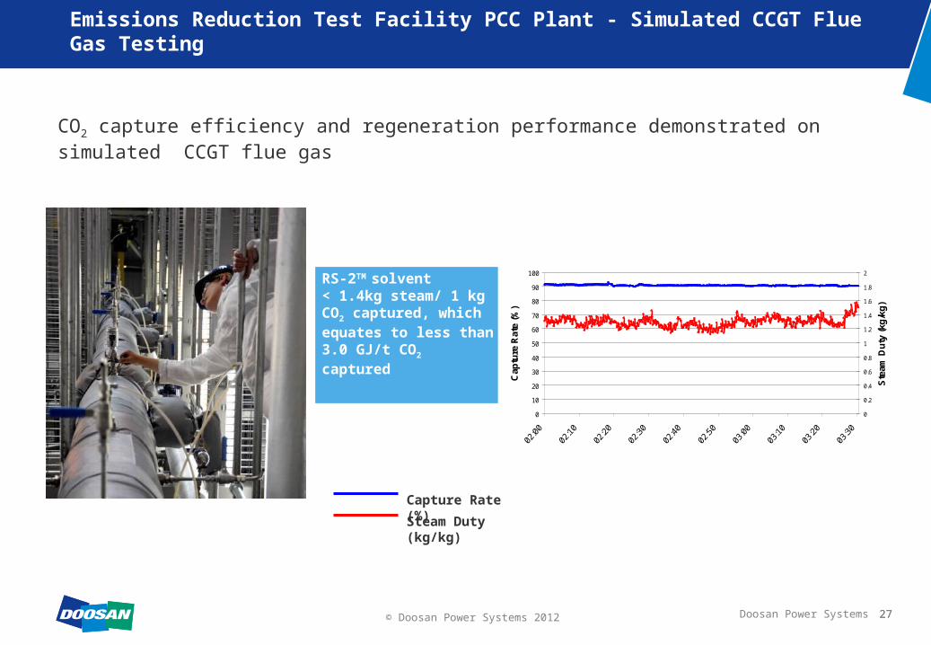
Emissions Reduction Test Facility PCC Plant - Simulated CCGT Flue Gas Testing
CO2 capture efficiency and regeneration performance demonstrated on simulated CCGT flue gas
RS-2TM solvent< 1.4kg steam/ 1 kg CO2 captured, which equates to less than 3.0 GJ/t CO2 captured
Capture Rate (%)
Steam Duty (kg/kg)
27
0
10
20
30
40
50
60
70
80
90
100
Cap
ture
Rat
e (%
)
0
0.2
0.4
0.6
0.8
1
1.2
1.4
1.6
1.8
2
Ste
am D
uty
(kg
/kg
)

28Doosan Power Systems© Doosan Power Systems 2012 28
Emissions Reduction Test Facility PCC Plant
Next steps:
Carry out off-gas emissions measurement and control trials
Continue to optimise the process
Reduce solvent regeneration energy consumption
Support for commercial bids:– Capturing carbon dioxide from coal and natural
gas flue gas – diverse product offering
– Test materials and techniques to reduce capital and operational expenditure on larger scale plant
– Demonstrate plant functionality and flexibility to clients

29Doosan Power Systems© Doosan Power Systems 2012 29
CCPilot100+ Ferrybridge

30Doosan Power Systems© Doosan Power Systems 2012 30
Ferrybridge CCPilot100+
PCC demonstration plant using DPS’ technology
100 t/day slip stream from a 500MWe unit on SSE’s Ferrybridge Power Station, making it the largest PCC demonstration in the UK
Two year test programme, fast-tracked build, operating March 2012
Funded by all the project partners
Lessons learned to be incorporated into future designs

31Doosan Power Systems© Doosan Power Systems 2012 31
CCPilot100+ Project Location
Pictures courtesy Google Earth

32Doosan Power Systems© Doosan Power Systems 2012
Complementary R&D Projects
1. Techno-Economic Optimisation A steady-state HYSYS model (calibrated with real data) combined with an economic model to be used for design and cost optimisation.
2. Analysing Degraded solvent Use of various analytical techniques (GC-MS, LC-MS, HPLC-RID) to characterise degraded solvent and identify preferred techniques for analysis
1. Amine Waste Water TreatmentCharacterisation of waste water streams from CCPilot100+ and identification of alternative waste water treatment methodologies
1. COMCATBuild and site test a novel monitoring apparatus that utilises a unique combination of well known instruments to monitor solvent loading in real time
2. TRACTION Use a dynamic model to investigate operation at transient loads to suit market demand for flexibility.
1. Amine Degradation Product ModellingAdapt an existing kinetic chemical reaction model for atmospheric amine degradation product emissions and calibrate it with actual plant measurements to predict solvent degradation products.

33Doosan Power Systems© Doosan Power Systems 2012
Wider Academic Involvement
One-Month Secondments ( 24 Students )– From Edinburgh, Leeds, Nottingham, Sheffield and Imperial College– Aimed at MSc / PhD / Eng Docs who will complete an additional on-site project to further their
understanding of CCS and the as-built CCPilot100+ plant
Industrial Awareness Module ( ~40 Students )– From Edinburgh, Leeds, Nottingham and Sheffield– 1 week split between Renfrew and Ferrybridge focused on process safety and deployment of
CCS.
1 Day Visits ( >400 students, ~14 Visits) – From Edinburgh, Leeds, Nottingham, Sheffield, Imperial College, York, Durham, Lancaster,
Manchester and Newcastle– Lectures on the power station and electricity generation and the PCC process, its
commercialisation and economic drivers
5 day short course on CCS via the Continuing Professional Development (CPD) Unit at University of Leeds and as a 10-credit MSc course at University of Strathclyde
Other industrial and research organizations are being invited (and requests being considered) to visit the CCPilot100+ during operation.

34Doosan Power Systems© Doosan Power Systems 2012 34
Simulation & modelling
CCPilot100+ Project Execution
Testing program
P&IDs & engineering
Column fabrication & deliveryConstruction
3D modelling
Current stage

35Doosan Power Systems© Doosan Power Systems 2012 35
35
CO2 capture rate and product compositions
Steam consumption at re-boiler Amine and degradation product atmospheric emissions Absorber column efficiency
– Column CO2 composition and temperature profiling
Power and water consumption under differing operating regimes Use different process configurations to optimise thermal
integration Solvent testing and formulation for efficiency and durability Performance of construction materials including polymers Comparison of performance with other pilot plant for scale-up
CCPilot100+ Test Programme Key Parameters

36Doosan Power Systems© Doosan Power Systems 2012
Process Measurement & Control - CCPilot100+
Gas and solvent flow rates, temperatures and pressures
On-Line Gas Analysis– FTIR – Extractive multi-point heated sampling system– Ammonia Tuneable Diode Laser – Cross-duct, non-
extractive– ppm Oxygen Micro-Fuel Cell – Extractive cold sampling
system
Manual Gas Analysis– FGD Polisher Performance– PCC – Based Emissions
– Solvent Carryover– Degradation Products
Process conditions and gas analysis

37Doosan Power Systems© Doosan Power Systems 2012
On-Line Solvent Analysis– Solvent Concentration – On-Line Titration
– CO2 Loading – On-Line Titration
Off-Line Solvent Analysis– Solvent Composition – Ion Chromatography– Solvent Concentration - Titration
– CO2 Loading – Titration and Gas/Liquid Displacement
PCC Chemistry Lab in Renfrew – Lab-Based Degradation Trials– Jacketed reactor used to run long-term
degradation trials simulating both coal and gas firing via control of CO2 and O2
Solvent analysis – Major Parameters
Process Measurement & Control - CCPilot100+

38Doosan Power Systems© Doosan Power Systems 2012 38
CCPilot100+ Current Status
Commissioned to run on MEA
Plant handed over to SSE Operations Group on 22nd March 2012
1000 hours of running time recorded to date on 30% MEA with water. Plant optimisation on-going.
UK Environment Agency and SSE interface
– positive dialogue
– supportive of emissions measurement & control to develop standards during the test programme

39Doosan Power Systems© Doosan Power Systems 2012
CCPilot100+ MEA Test Results
MEA preliminary results show good agreement with publically available test data– typical quoted values of 3.6 to 3.9 GJ/t CO2
39

40Doosan Power Systems© Doosan Power Systems 2012
CCPilot100+ Operating Experience
Good working relationships developed with– SSE Ferrybridge Station and CCPilot100+ staff
– Environment Agency
– Main process plant item suppliers
– C&I equipment suppliers
– Analytical instrument suppliers
Commissioning– Development of analytical techniques
– On-line solvent analysis instrumentation
Testing– Selection of manual gas analysis contractor
– Liaison with Environment Agency
40

41Doosan Power Systems© Doosan Power Systems 2012
Cost Reduction - PCC Materials
Installation Cost (i.e. raw material cost + fabrication cost)
– must be competitive in relation to ‘standard’ construction materials (e.g. carbon steel, concrete)
– must be site-friendly and not too labour-intensive
Operating Cost (i.e. degree of process interaction)
– minimize material losses due to corrosion/degradation (repair outages)
– minimize contamination of PCC solvent (solvent make-up reagent and/or outages)
– minimize fouling of surface (cleaning outages)
Track Record (i.e. perceived level of commercial risk)
– preferably in PCC or in amine-based natural gas purification
– composite track record from several related industries may be acceptable
– demonstration may be required (difficult due to the risk to the project)
In theory, cost reduction is the single biggest driver
In practice, track record has historically dominated pilot-stage materials selection

42Doosan Power Systems© Doosan Power Systems 2012 42
PCC materials testing
Materials Selected Stainless steels Duplex alloys Solid polymers Structured polymer
composites Polymer-based coatings
All on test at CCPilot100+ in the harshest survivable environments on the plant
Full suite of construction/application procedures
Further industrial-scale trialling

43Doosan Power Systems© Doosan Power Systems 2012
2nd Generation PCC Technologies
Technology Brief Description Potential Benefits vs 1st Gen Perceived Cons
Solid sorbents
Monolithic structures using low temperature swing adsorbents
< CAPEX/OPEX, and < energy penalty Potentially limited to gas-fired plants due to poisoning by contaminants in coal flue gas
High temperature swing adsorbents – Calcium looping
< CAPEX and < energy penalty High attrition, poisoning of the sorbent, > OPEX
Immobilized amines
Immobilized amines – looping technology
Electrical swing adsorption < CAPEX > OPEX, > Energy penalty, unclear regeneration process
Advanced Liquid Solvents
Ionic liquids (IL) (incl. amino acid salt solutions)
Non-toxic solvent, low solvent carryover due to low vapour pressure and environmentally safe
Expensive, > OPEX due to multi-step regeneration, And scale-up difficulties
Amine-based solvents Well developed technology and many demonstrations underway
> CAPEX/OPEX, environmental concerns, limit on minimizing energy penalty
Aminosiloxanes-based solvents Low solvent carryover due to low vapor pressure
Non-aqueous solvent – problems with condensed moisture
Enzyme-promoted K2CO3
solventsNon-toxic solvent, Low temperature regeneration
Low temperature stripping (ultrasonic stripping being developed)
MembranesHollow fibre membranes No moving parts,
no reagent usage andlow footprint (for Metal organic frameworks)
Membrane integrity, > OPEX,mechanical stability through use of support structures, particulate blocking/poisoningNanocomposite/ Nanostructured polymeric
membranes
Cryogenics Chill flue gas to condense and separate CO2 < CAPEX Higher parasitic power, > OPEX

44Doosan Power Systems© Doosan Power Systems 2012
Monolithic Structures Using Low Temperature Swing Solid Sorbents
Objectives: Development of InvenTyS’ VeloxoTherm™ technology (based on a Temperature Swing adsorption process) using a proprietary structured sorbent in a rotating frame (similar to regenerative air heaters used in power plants) for NGCC PCC applications
Potential Benefits: A proven technology with a demonstrated reliability and simplicityEnvironmental: Low levels of waste water generatedOPEX : (i) Lower regeneration energy (< 50% of the conventional amine process) and (ii) High sorbent lifecycle (reducing replenishment costs)CAPEX: (i) Low footprint due to integrated design of the adsorber and stripper into a Rotary Adsorption Machine (RAM)
Project Partners: InvenTyS, Howden, Rolls Royce, MAST Carbon and Doosan Power Systems

45Doosan Power Systems© Doosan Power Systems 2012
Enzyme Activated K2CO3 Process with Ultrasonic Regeneration
Objectives: An integrated bench-scale PCC system that combines the attributes of a bio-renewable enzyme catalyst with low-enthalpy absorption solvent and novel ultrasonically-enhanced regeneration system
Potential Benefits:Environmental: Benign solvent leads to low emissions and degradation productsOPEX : Low, (i) Enzyme is not susceptible to degradation by other flue gas components such as SO2, O2 etc and (ii) Lower regeneration energy (< 50% of the conventional amine process)
CAPEX : Low, (i) Lower operating temperatures and relatively non-corrosive solvent allows the use of less expensive materials (ii) No FGD polisher needed due to enzyme’s resistance to SOx in the flue gas, however a suitable HSS removal methodology will be adopted
Project Partners: Novozymes North America, Pacific Northwest National Laboratory, University of Kentucky and Doosan Power Systems

46Doosan Power Systems© Doosan Power Systems 2012
Next Steps
Pursue large demonstration projects CCPilot100+
– Run RS-2™ testing – Q4 2012– Advanced solvent testing - through 2013– Advanced PCC materials testing through
2012 and 2013– On-line liquid & gas analyses throughout
test programme ERTF
– Off-gas emissions measurement and control
– Continued process optimisation– Support commercial bids
Solvent Development– Performance assessment– Degradation characterisation
Feasibility studies & pilot-plant scale demonstration of 2nd generation PCC technologies

47Doosan Power Systems© Doosan Power Systems 2012 47
Front End Engineering Design (FEED) Studies
Application of the process technology to real projectsC
oal
-Fir
ed B
oile
rsN
GC
C
Flue gas type: NGCC exhaust Full flue gas processing of a
single 230MWe gas turbine Ultra low pressure drop
design Feasibility study completed
2011
Flue gas type: coal-fired flue gas Four oil-fired gas boilers being
converted to bituminous coal-firing
Competing for NER 300 funding FEED completed Q2 2011
CO2 from the adjacent Dakota Gasification Company (~3.0 MTPY) is sold for enhanced oil recovery
FEED completed November 2010
Flue gas type: NGCC exhaust
Configuration: two absorbers and one stripper
FEED completed 2009
Basin Electric, AVS, 3,000 t/day ENEL, Porto Tolle, 4,200 t/day
Statoil Karsto, 3,000 t/day SSE, Peterhead, 3,300 t/day

48Doosan Power Systems© Doosan Power Systems 2012
Emissions reduction test facilities
1 t/day to 4 t/day CO2
Slipstream
100 t/day CO2 ≈ 5MWe
Ferrybridge
Large demonstration project(s) slipstream
~3000 t/day CO2 ≈ 150MWe
Commercialisationfull-scale plant
10,000 t/day CO2 ≈ 500MWe
15,000 t/day CO2 ≈ 800MWe
Doosan Power Systems Post Combustion Roadmap
2012

49Doosan Power Systems© Doosan Power Systems 2012
Outline
Introduction
Background - CO2 emissions and electricity generation
CO2 reduction strategies
CO2 capture technologies
Development of PCC technology at DPS
PCC Challenges-Technical
PCC Challenges-Non technical
Concluding remarks
Q&A

50Doosan Power Systems© Doosan Power Systems 2012
50
Safety Issues - CO2
Most of plant will operate under suction But from FGR fan through to the
windbox / burners the system is under pressure, and may leak
CO2 is denser than air and will collect in low level confined spaces i.e. in the basement areas Buoyancy helps dispersion
Good ventilation is essential How do you ensure this? Would you trust your life to a CFD
model?
The Dangers of Carbon Dioxide
1000ppm 0.1% Prolonged exposure can affect powers of concentration
5000 ppm 0.5% The normal international Safety Limit (HSE, OSHA)
10,000ppm 1% Your rate of breathing increases very slightly but you probably will not notice it.
15,000ppm 1.5% The normal Short Term Exposure Limit (HSE, OSHA)
20,000ppm 2% You start to breathe at about 50% above your normal rate. If you are exposed to this level over several hours you may feel tired and get a headache.
30,000ppm 3% You will be breathing at twice your normal rate. You may feel a bit dizzy at times, your heart rate and blood pressure increase and headaches are more frequent. Even your hearing can be impaired.
40,000-50,000ppm 4-5% Now the effects of CO2 really start to take over. Breathing is much faster - about four times the normal rate and after only 30 minutes exposure to this level you will show signs of poisoning and feel a choking sensation.
50,000-100,000ppm 5-10% You will start to smell carbon dioxide, a pungent but stimulating smell like fresh, carbonated water. You will become tired quickly with laboured breathing, headaches, tinnitus as well as impaired vision. You are likely to become confused in a few minutes, followed by unconsciousness.
100,000ppm-1,000,000ppm 10-100% Unconsciousness occurs more quickly, the higher the concentration. The longer the exposure and the higher the level of carbon dioxide, the quicker suffocation occurs.
15 minutes
8 hours
Can we be sure that we will never exceed safe levels of CO2?

51Doosan Power Systems© Doosan Power Systems 2012
51
PCC Challenges
There is, at present, commercial risk associated with CO2 capture in general:
Technical– Process Design and Chemistry– Scalability– Materials Selection
Environmental– Emissions from the PCC plants, their characterisation, impact and mitigation
Social
Financial
Legislative

52Doosan Power Systems© Doosan Power Systems 2012
52
Technical Challenges – Process Design and Chemistry
PCC process design depends on the characteristics of the flue gas, solvent and the required CO2 capture efficiency.
The following are typical characteristics of flue gas from coal-fired power plants– High volume flow rates
– Low CO2 concentration (~15% v/v for coal power plants, and ~4% v/v for gas plants)
– Low gas pressures
The baseline design of CO2 capture plants above or equal to 90% carbon capture efficiency represents the final objective. This, however, is to be achieved at very low capital and operational costs for the technology to be competitive.
Capital Costs: Represent the cost of the plant equipment & components: Absorber, stripper, pumps, heat exchangers etc.
Operation Costs: Solvent life, Parasitic losses including steam for solvent regeneration

53Doosan Power Systems© Doosan Power Systems 2012
53
Technical Challenges – Process Design and Chemistry
Because process design is an iterative process, advanced simulation capabilities need to be developed. These can be a mixture of commercially available and in-house (proprietary) process simulators
Commercial process design tools used by technology developers; Aspen Plus ® Aspen HYSYS® ProTreat® ProMax ®
Simulation software models need to be evaluated for their performance prediction before they can be used for designing large-scale plants.

54Doosan Power Systems© Doosan Power Systems 2012
54
Technical Challenges – Process Design and Chemistry
Accurate estimation of process parameters for Process Design is the key!
Equilibrium concentrations – Thermodynamics
Enthalpies of formation of the components – Standard databases – Scarcity of data for alkanolamine ions
Estimated using equilibrium constants data – Measured temperature ranges
Heat exchanger design fundamental parameters– Fluid mechanics (geometry, fluid velocity)– Fluid properties (density, viscosity, thermal conductivity, specific heat capacity) – Heat transfer coefficients

55Doosan Power Systems© Doosan Power Systems 2012
55
Technical Challenges – Scalability
One of the major challenges is the ability to scale carbon capture plants to large power plant capacity (>500 MWe) within reasonable cost and footprint.
For sizing a full-scale power plant (>400 MWe), realistic assumptions on the size of equipment, the foot-print and the technical complexity in terms of equipment integration and construction required to achieve 90% capture should be considered.
ERTF CCPilot100+ Basin Electric
Plant Capacity (tpd) 1 tpd 100 tpd 3000 tpd
Plant Size 160 kWt 5 MWe 125 MWe
PCC Design Gas Flow (kg/h) 230 28, 245 700,346
CO2 capture (%) 90% 90% 90%
CO2 Absorber Dimensions (dia x height: m) 0.25 x 9 2.3 x39 11.8 x 45.4
Stripper Column Dimensions (dia x height: m) 0.20 x 8 1.1 x 30.5 5.5 x 30.5

56Doosan Power Systems© Doosan Power Systems 2012
56
Technical Challenges – Material Selection
Commonly used SS grades have a high cost/tonne.
Certain SS grades are also susceptible to Stress Corrosion Cracking (SCC) at higher
temperatures.
Certain SS grades can also corrode in the presence of solvent degradation products.
Lower cost CS materials are unsuitable because of lower corrosion resistance when
compared with SS grades.
Way forward
Develop cheaper materials and/or metal coatings (e.g., Concrete)
Utilise Corrosion inhibitors (can reduce solvent performance)
Develop environmentally friendly, non-corrosive solvents

57Doosan Power Systems© Doosan Power Systems 2012
57
Environmental Challenges
Sources of Emissions from PCC Plant
Solvent/Degradation products carry-over
Solvent/Degradation products carry-over

58Doosan Power Systems© Doosan Power Systems 2012
58
Environmental Challenges – Solvent Degradation
Amine Degradation Products
It is difficult to describe the degradation chemistry of amines in CO2 capture succinctly due to; Different types of degradation mechanisms involved Different grades of amines used by different PCC vendors
Computational chemistry & modelling approaches have been used to predict the most likely amine degradation products in PCC which do not necessarily exist in reality.
“Verified and publicly available PCC plant emission data is not only incomplete but, in many cases, rely on tests which are not performed under representative conditions. Most impact assessment studies have been carried out in dry atmosphere and do not address reactions that develop in the water phase, during darkness and with other radicals present (other than hydroxide) – all of which can remove degradation products. The result is an overestimation of the level of degradation product concentrations and their persistence in the atmosphere”.
Source: HSE Impact Assessment of Amine-based Solvents in CO2 Capture, ZEP report (2011)

59Doosan Power Systems© Doosan Power Systems 2012
Environmental Challenges – Solvent Degradation
Health Risks: Literature studies have found that;
Most amines are biodegradable and hence, have little adverse environmental impact
The highest concentrations (if emitted) would be found in liquid phase within 1 km of the emitting PCC plant
Nitrosamines and nitramines are potential carcinogens, but have short lifetimes of 1h and upto 3 days, respectively in the atmosphere.
Where these emissions occur, their concentrations range from parts per million (ppm) to parts per billion (ppb).
59

60Doosan Power Systems© Doosan Power Systems 2012
60
Environmental Challenges – Solvent Degradation
1. In-Plant Degradation
In the PCC Plant, solvent degradation can occur by thermal breakdown, oxidation and reactions with acid gases (NOx and SOx). The PCC plant will be operated to minimise the formation of any degradation products during the capture process.
Thermal degradation in the presence of CO2 typically occurs due to reactions of amines with CO2 at excessive localised reboiler surface temperatures (130 to 150 oC), forming oxazolidones. To mitigate, reboiler temperatures are kept at about 120 oC.
Oxidative degradation occurs in the absorber column due to the reaction of amines with flue gas oxygen and sulphur dioxide.
Heat Stable Salts (HSS) are also produced from the reaction of amines with acid gases (NOx and SOx). Absorber inlet NOx and SOx concentrations are typically controlled to less
than 100 ppm and 10 to 20 ppm respectively.

61Doosan Power Systems© Doosan Power Systems 2012
61
Environmental Challenges – Solvent Degradation
2. In-Plume Degradation
Amine emissions in the off-gas can degrade further in the plume if the concentration of contaminants, particularly NOx, are high, to produce amides, nitrosamines and nitramines. However, NOx concentration in the plume will be low due to the low NOx requirements at the inlet of the PCC plant.
3. Environmental Degradation
Amines undergo atmospheric degradation through absorption, adsorption, & photolysis processes. Generally, environmental degradation of amines is initiated by reaction with OH - radicals and, in sunlight, by photolysis.

62Doosan Power Systems© Doosan Power Systems 2012
62
Environmental Challenges – Control Measures
Current Control Measures
Gas borne emissions from the PCC absorber are controlled through dissolution in water wash section(s) installed at the absorber off-gas exit.
Droplets of amine solution, which also contain degradation products in suspension and solution, could be entrained in the absorber off-gas stream and potentially escape to the atmosphere. Absorber/water wash column demisters are typically designed to minimise such entrainment.
Degradation products in the solvent solution are typically controlled to a total concentration of 2% w/w through solvent reclamation methods (thermal, Ion exchange etc).

63Doosan Power Systems© Doosan Power Systems 2012
Outline
Introduction
Background - CO2 emissions and electricity generation
CO2 reduction strategies
CO2 capture technologies
Development of PCC technology at DPS
PCC Challenges-Technical
PCC Challenges-Non technical
Concluding remarks
Q&A

64Doosan Power Systems© Doosan Power Systems 2012
64
Public perception - Introduction
Source: Carbon capture & Storage association
Positive public perception is critical to the success of CCS
- Direct impact on specific projects
- Influence on Government CCS policy
- Public acceptance can be difficult to win and easy to lose
Academic studies have shown low levels of public knowledge of CCS, including in UK
- How the public learns of CCS is key to what they think of it
- Some evidence that greater public familiarity with CCS can correlate with greater public concern

65Doosan Power Systems© Doosan Power Systems 2012
65
Public perception of CCS
Source: Carbon capture & Storage association
Building public understanding, awareness and acceptance is key to CCS deployment.

66Doosan Power Systems© Doosan Power Systems 2012
66
Other Challenges – Financial & Legislation
FINANCIAL Current Issues
- How much is CCS going to cost?- How much energy will CCS require?
CCS Government funding/subsidy insufficient/lack of clarity
- Impact of Recession ?
LEGISLATION Lack of adequate legal & regulatory framework Lack of commitment from major polluters (US, Canada, Brazil, Russia, India, China etc.)
66

67Doosan Power Systems© Doosan Power Systems 2012
67
Concluding Remarks – The Way Forward
The time is right for the full-scale demonstration of PCC technology
Considerable progress has been made in the development of PCC technology
-The process is technically viable
-The process is reasonably well understood
-The process has been demonstrated at pilot-scale
-The process is being demonstrated at large-scale (100+ t/day)
-Most of the individual components are in commercial operation at the required scale
PCC technology is economically competitive with alternative carbon capture technologies

68Doosan Power Systems© Doosan Power Systems 2012 68
In Summary
As such it is focussed on, and driving towards CCS commercialisation
Underpinning its existing technology offering
Improving the technology offering through capital and operational cost reduction
Working closely with utilities and environmental agencies to develop measurement and control standards to bolster confidence in post-combustion capture
Doosan is a forward looking, technology driven organisation, positioned to take advantage of future markets
Low impact high efficiency integrated EPC carbon capture solutions

69Doosan Power Systems© Doosan Power Systems 2012
Contact Details
Dr Saravanan Swaminathan
Senior Engineer, Product Development
Mark Bryant
Director Carbon Capture
Matthew Hunt
Business Development Manager
Indian Office Contact details to be added?
Doosan Power Systems Limited Porterfield Road Renfrew PA4 8DJ United Kingdom
T +44 (0)141 886 4141
69

Thank youDisclaimer:The contents in this presentation are for information purposes only and are not intended to be used or relied upon by the reader and are provided on the condition that you 'use it at your own risk'. Doosan Power Systems Limited does not accept any responsibility for any consequences of the use of such information.
All rights are reserved and you may not disseminate, quote or copy this presentation—written by Doosan Power Systems Limited—without its written consent.