dosimetry and calibration of outline photon and … - chapter 13...1 dosimetry and calibration of...
TRANSCRIPT

1
Dosimetry and calibration of
photon and electron beams
with cavity ion chambersChapter 13
F.A. Attix, Introduction to Radiological Physics and
Radiation Dosimetry
Almond et al., AAPM’s TG-51 protocol for clinical reference
dosimetry of high-energy photon and electron beams, Med.
Phys. 26, pp.1847-1870, 1999
McEwen at al., Addendum to the AAPM’s TG-51 protocol, Med.
Phys. 41, pp. 041501-1-20, 2014
Outline
• General considerations
• Calibration of ion chambers
– For photon beams
– For electron beams
• Reference dosimetry of photon beams
• Reference dosimetry of electron beams
Introduction
• The success of radiation therapy depends on the accuracy of a prescribed dose delivery
• This necessitates high accuracy in the dosimetry of high-energy photon and electron beams
• Two aspects are involved:
– proper calibration of the measuring instruments (ionization chamber and electrometer)
– characterization of clinical beams
Ion chamber calibration
• Ion chamber can serve as an absolute dosimeter if its
gas mass is known
• Most of the commercially manufactured ion chambers
are not constructed with exactly known sensitive
volume, therefore they require calibration
• National laboratories maintain standard ionization
chambers and calibrated g-ray beams
• Regional calibration laboratories (ADCL - Accredited
Dosimetry Calibration Laboratories in US) provide
calibration services for general-use instruments for a fee
Ion chamber calibration
• Three approaches to ion chamber calibration:
– Exposure Nx
– Dose in cavity gas Ngas – old TG-21 protocol
– Absorbed dose in water ND– new TG-51 protocol
• Beam dosimetry can be done
– In free space
– In water phantom (need correction for field
perturbation due to chamber insertion)
Ion chamber calibration
• Starting from an ion chamber calibrated free-in-air for one quantity (exposure or air kerma) and transferring this information to obtain another quantity, absorbed dose to water, based on a measurement in a phantom introduces complexity and possible errors
• To overcome these complexities, primary standards laboratories have developed standards for absorbed dose to water in photon beams from 60Co and accelerator beams and these have an uncertainty of 1% or less

2
TG-51 protocol
• Prescribes a methodology for clinical reference dosimetry
• Applies to photon beams with nominal energies between 60Co and 50 MV, and electron beams with nominal energies between 4 and 50 MeV
• Uses ion chamber calibrated in terms of absorbed dose to water in a 60Co beam
• Sets up certain well-defined reference conditions
• Starting point: an ion chamber with calibration factor directly traceable to national standards of absorbed dose (may be done through ADCL)
General formalism
• Given NQD,w (in Gy/C or Gy/rdg), the absorbed-
dose to water calibration factor for an ion chamber located in a beam of quality Q
• Under reference conditions:
where DQw is the absorbed dose to water (in Gy) at
the point of measurement of the ion chamber when it is absent and M is the fully corrected electrometer reading in coulombs (C) or meter units (rdg)
(Gy) ,
Q
wD
Q
wMND
General formalism: kQ
• Usually absorbed-dose calibration factors will be
obtained for reference conditions in a 60Co beam
• Define the quality conversion factor, kQ, such that
• The quality conversion factor kQ is chamber specific
• Using kQ, gives
(Gy) 60
,
Co
wDQ
Q
wNMkD
Gy/rdg)or (Gy/C 60
,, NkN
Co
wDQ
Q
wD
General formalism: kQ
• Recall Spenser-Attix cavity theory, stating:
• Thus
airair
airscorrection
med
air
airmede
W
m
MDP
LDD
,
60
60
,
,
Co
scorrection
w
air
Q
scorrection
w
air
Co
wD
Q
wD
Q
PL
PL
N
Nk
Pcorrections – accumulates
various chamber-
related corrections
(wall, dose gradient,
change in electron
fluence inside the
chamber, etc.)
General formalism: kQ
• For photon beams, the protocol provides
values of kQ for most cylindrical ion
chambers used in reference dosimetry
(extended list in Addendum to TG-51)
• Plane-parallel chambers are not included
because there is insufficient information
about wall correction factors in photon
beams other than 60Co beams
General formalism: kQ
• For electron beams the quality conversion factor kQ
contains two components:
• PQgr is necessary only for cylindrical chambers
– corrects for the ionization gradient at the measurement point
– depends on the radius of the chamber cavity and
– must be measured by the user, the protocol provides a procedure for measuring PQ
gr in the user’s electron beam
• kR50 is a chamber-specific factor, a function of electron beam quality as specified by R50 (depth in water where dose falls off to 50% of maximum dose)
50R
Q
grQkPk
3
General formalism: kQ
• The factor kR50 is written as the product of:
• kecal is the photon-electron conversion factor (fixed
for a given chamber model), it is the value needed to
convert into , the absorbed-dose
calibration factor in an electron beam of quality Qecal
• k´R50, is the electron beam quality conversion factor,
beam quality dependent, and converts into
ecalRRkkk
5050
60C o
,D wN
ecal
,
Q
D wN
ecal
,
Q
D wN
Q
wDN
,
General formalism
• In an electron beam, the dose is given by
• The reference depth for electron-beam dosimetry is at dref = 0.6R50 – 0.1 cm, which is essentially at the depth of dose maximum for beams with energies <10 MeV but is deeper for higher-energy beams
• At this depth the protocol can make use of stopping-power ratios, accounting for the realistic (not mono-energetic) energy distributions of electron beams
(Gy) 60
50 ,
Co
wDecalR
Q
gr
Q
wNkkMPD
General formalism
• Cylindrical chambers are preferred dosimeters
• The protocol allows and provides data to carry through the above approach using plane-parallel chambers, although there is evidence that minor construction details significantly affect the response of these detectors in 60Co beams, making the measurements or calculations of kecal more uncertain
• Plane-parallel chambers should be cross calibrated in high-energy electron beams against calibrated cylindrical chambers
General formalism
• To use this formalism one starts by obtaining
an absorbed-dose to water calibration factor
for an ion chamber in a 60Co beam
• The next step is to determine the quality
conversion factor, kQ, for the chamber being
used
– This step requires characterization of the beam
quality Q
Obtaining an absorbed-dose to
water calibration factor• The absorbed-dose calibration factor is defined as
where is the absorbed dose to water (in Gy) in the calibration laboratory’s 60Co beam at the point of measurement of the ion chamber in the absence of the chamber
• It applies under standard environmental conditions of 22 °C, 101.33 kPa, and relative humidity between 20% and 80%, respectively (in the US and Canada)
• It must be traceable to the user’s national primary standard for absorbed dose to water
60
60C o
C o
, (G y/C or G y/rdg)
w
D w
DN
M
Co
wD
60
Obtaining an absorbed-dose to
water calibration factor
• The ion chamber should be checked for any
problems before it is sent for calibration
• The ion chamber and the electrometer with
which it is to be used should both be
calibrated, possibly as a single unit
• All ranges of the electrometer that are
routinely used for clinical reference
dosimetry should be calibrated

4
Chamber waterproofing
• A chamber is calibrated and used clinically in water
• Equivalent waterproofing techniques must be used
for measurements in the user’s beam and in the
calibration laboratory
• If a chamber is not inherently waterproof (preferred
method) it requires extra waterproofing sleeves
• A waterproofing sleeve should minimize air gaps
near the chamber wall (0.2 mm) and should be
made of PMMA 1 mm thick
Measurement phantoms
• Clinical reference measurements must be performed
in a water phantom with dimensions of at least 30
30 30 cm3 (non-water phantoms are prohibited)• If the beam enters through the
plastic wall of the water phantom
and the wall is >0.2 cm thick, all
depths should be scaled to water-
equivalent depths by measuring
from the outside face of the wall
with the phantom full of water and
accounting for the wall density
Charge measurement
• The fully corrected charge reading from an ion chamber, M, is given by
where Mraw is the raw ion chamber reading in coulombs, C, or the instrument’s reading units (rdg)
– PTP is the temperature–pressure correction;
– Pion corrects for incomplete ion collection efficiency
– Ppol corrects for polarity effects
– Pelec takes into account the electrometer’s calibration factor
if the electrometer and ion chamber are calibrated separately
rdg)or (C rawpolelecTPion
MPPPPM
Shutter timing error – Co-60 only
when a preset time has elapsed, the t
measured by the timer may not agree
exactly with the t´ representing the
shutter-open period
• This can be detected by making two
measurements X1 and X2 for different
timer settings, t1 and t2 and
calculating beam shutter timing error:
• Any shutter timing error must be accounted for if needed
• If a beam shutter is used with a timer that closes the shutter
12
2112
XX
tXtX
Polarity corrections
• Polarity effects vary with beam quality and other conditions such as cable position
• It is necessary to correct for these effects each time clinical reference dosimetry is performed
• Taking reading with both polarities applied, M+raw and M-
raw
• Mraw (one of M+raw or M-
raw) is the reading corresponding to the charge collected for the reference dosimetry measurements in the clinic (should be the same as for the chamber calibration)
• Polarity correction should be less than 0.3% (Addendum to TG-51 allows for 0.4%)
+ -
raw raw
pol
raw2
M MP
M
Electrometer correction factor
• If the electrometer is calibrated separately from the
ion chamber, the electrometer correction factor, Pelec,
is just the electrometer calibration factor, correcting
the electrometer reading to true coulombs
• It is common practice in the US to calibrate ion chambers and electrometers separately
• It is common practice in Canada to calibrate them as a unit, in which case Pelec =1.00
• Also Pelec =1.00 for cross-calibrated plane-parallel chambers since it cancels out of the final equations

5
Standard environmental conditions
• Since calibration factors are given for standard
environmental conditions of T0 = 22°C and P0 = 101.33
kPa (1 atmosphere), one corrects charge or meter
readings to standard environmental conditions by
• It is assumed that the relative humidity is always in the
range of 20% to 80%, with the reading error ±0.15%
• Chambers require time (usually 5 to 10 min) to reach
thermal equilibrium with their surroundings
TP
273.2 101.33
273.2 22.0
TP
P
Corrections for ion-chamber
collection inefficiency
• The recombination correction factor Pion is used to correct ion chamber readings for lack of complete collection efficiency
• Pion is a function of the dose per pulse in an accelerator and thus will change if either the pulse rate for a fixed dose rate, or the dose rate is changed
• The correction must be measured in each set of experimental conditions for which clinical reference dosimetry is being performed
• The value of Pion should be less than 1.05
Measuring Pion
• The standard two-voltage techniques should be used:
the charge produced by the ion chamber is measured in
the beam of interest when two different (by at least a
factor of 2) bias voltages are applied
• Let VH be the normal operating voltage for the detector
(always the higher of the two voltages in these
measurements), and MHraw be the raw chamber reading
• After measuring MHraw the bias voltage is reduced to
VL, and once the chamber readings have reached
equilibrium (takes several minutes), MLraw is measured
Measuring Pion
• Although initial recombination may dominate, for continuous (i.e., 60Co) beams, the two-voltage formula gives an estimate of the general recombination
• For pulsed or pulsed-swept beams with Pion < 1.05
2
ion 2
raw raw
1. /
/ /
H L
HH L
H L
V VP V
M M V V
ion
raw raw
1. /
/ /
H L
H H L
H L
V VP V
M M V V
Beam quality specification
• For both photon and electron beams from accelerators, the beam quality must be specified in order to determine the correct value of the quality conversion factor, kQ or the electron quality conversion factor, k´R50
• For a 60Co beam the factor kQ = 1.000 by definition
• Beam quality must be measured each time clinical reference dosimetry is performed for accelerator beams
Beam quality specification
• Beam quality is characterized by a parameter related to the central-axis depth-dose curves for the beam
– For photons it is %dd(10) – the percentage depth dose at 10 cm depth in water due to photons only
– For electrons it is R50 – the depth in water in cm at which the absorbed dose falls to 50% of the maximum dose
• It is essential to use SSD=100 cm when establishing the beam quality for photon and electron beams because %dd(10) and R50 are functions of SSD

6
Depth of measurement
• The point of measurement for a
cylindrical chamber is on the central
axis of the chamber and this is always
placed at the reference depth when
measuring dose at an individual point
• The effective point of measurement is upstream of the
point of measurement due to the predominantly
forward direction of the secondary electrons
• This results in shift of the depth-dose curve upstream
(to shallower depth)
Depth of measurement
• Effect of shifting depth-ionization data measured with cylindrical chambers
upstream a) by 0.6 rcav for photon beams and b) by 0.5 rcav for electron beams
(rcav=1.0 cm). The raw data are shown by curve I (long dashes), shifted data
by curve II (solid line). Electron beam curve must be further corrected
photon beam electron beam
Depth of measurement
• For cylindrical and spherical chambers the shift is taken as 0.6rcav for photon beams and 0.5rcav for electron beams, where rcav is the radius of the ionization chamber cavity
• The shifted curves are taken as the depth-ionization
curves for cylindrical chambers
• For plane-parallel chambers, the center of the front
(upstream) face of the chamber air cavity is the point
of measurement, no shift is needed
Depth of measurement
• Using these measurements as depth-ionization
curves ignores any variations in Pion and Ppol with
depth and for electron beams it also ignores any
variations in the electron fluence correction factor
• Since well-guarded plane-parallel chambers
minimize these variations with depth, they are
preferred for measuring electron beam depth-
ionization curves
Depth of measurement
• For photon beams the variation in stopping-power ratio is negligible past dmax (<0.1%) and thus the depth-ionization curve is treated as a depth-dose curve
– These same techniques should be used to determine any clinical photon beam depth-dose curve
• In order to determine depth-dose curves for electron beams, the depth-ionization curve must be further corrected for the significant change in the stopping-power ratio with depth
– This conversion is not needed in the protocol except to transfer the dose from dref to dmax if necessary
Depth of measurement
• In contrast to the depth-dose curve measurement,
for measurements of absolute dose at the reference
depth in both electron and photon beams, a
cylindrical chamber’s point of measurement is
placed at the referenced depth (10 cm for photons
and dref for electrons)
• The gradient effects are included implicitly in the
beam quality conversion factor kQ for photons and
explicitly by the term PQgr for electrons
7
Beam-quality specification for
photon beams
• The percentage depth dose at 10 cm depth in a water
phantom due to photons only, %dd(10)X , is defined for a
field size of 1010 cm2 at the phantom surface at an SSD of
100 cm
• At higher energies (about 10 MV and above), the electrons
from the accelerator head may significantly affect this dose
• Placing a 1 mm thick lead foil below the accelerator head
(about 50 cm from the phantom surface) reduces the
electrons contamination to a negligible level, thus %dd(10)Pb
is obtained (it actually replaces unknown contamination with
that due to Pb-foil)
Beam-quality specification for
photon beams• For beams with energies less than 10 MV, with
%dd(10)<75% the value of %dd(10) measured in the open beam is the beam quality, %dd(10)X
• For beam energies of 10 MV and above (and all FFF beams according to the Addendum), the value of %dd(10)X for the open beam is obtained from %dd(10)Pb parameter:
• If %dd(10)Pb is less than the thresholds given in the
equations, then %dd(10)x=%dd(10)Pb
X Pb Pb
Pb
% (10) 0.8905 0.00150% (10) % (10)
foil at 50 cm, % (10) 73%
dd dd dd
dd
Beam-quality specification for
photon beams• Alternative formula to correct for electron contamination for
higher energy beams (up to %dd(10)=89%):
• Here %dd(10) is measured for an open beam
• Leads to an error in kQ <0.25%
• The Addendum advocates use of this formula in place of Pb: “Although TG-51 clearly states that the foil must be removed for the dose measurement step,
there is anecdotal evidence of confusion as to when the lead foil must be used”
• TG-51 is not very sensitive to accurate accounting for electron
contamination (low error in kQ even if Pb foil is not used)
0.2010%267.110% ddddx
Beam-quality specification for
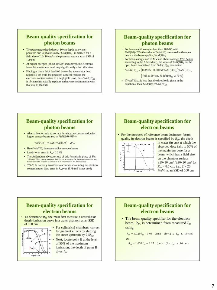
electron beams
in water (in cm) at which the
absorbed dose falls to 50% of
the maximum dose for a
beam, which has a field size
on the phantom surface
1010 cm2 (2020 cm2 for
R50 > 8.5 cm, i.e., E > 20
MeV) at an SSD of 100 cm
• For the purposes of reference beam dosimetry, beam
quality in electron beams is specified by R50, the depth
Beam-quality specification for
electron beams
• For cylindrical chambers, correct for gradient effects by shifting the curve upstream by 0.5rcav
• Next, locate point B at the level
of 50% of the maximum
ionization; the depth of point B
gives I50
• To determine R50 one must first measure a central-axis depth-ionization curve in a water phantom at an SSD of 100 cm
Beam-quality specification for
electron beams
• The beam quality specifier for the electron
beam, R50, is determined from measured I50
using
or
50 50 501.029 0.06 (cm) (for 2 10 cm)R I I
50 50 501.059 0.37 (cm) (for 10 cm)R I I
8
Photon beam dosimetry
• In photon beams
gives the absorbed dose to water under reference conditions
• Reference dosimetry for photon beams is performed in an open beam (i.e., without trays, wedges, or blocks) with the point of measurement of the cylindrical ion chamber placed at the reference depth which is a water-equivalent depth of 10 cm in a water phantom
(Gy) 60
,
Co
wDQ
Q
wNMkD
Reference conditions
• Either an SSD or an SAD setup can be used, the field
size is 1010 cm2
• When using an SSD setup, the field size is defined at
the surface of the phantom
• When an SAD setup is
being used, the field size is
defined at the detector
position which is placed at
10 cm depth at the isocenter
of the machine
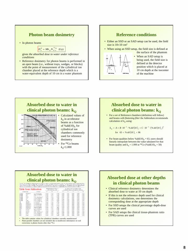
Absorbed dose to water in
clinical photon beams: kQ
• Calculated values of
kQ in accelerator
beams as a function
of %dd(10)X for
cylindrical ion
chambers commonly
used for reference
dosimetry
• For 60Co beams
kQ=1.000
Absorbed dose to water in
clinical photon beams: kQ
• For a set of Reference chambers (definition will follow)
and beams with flattening filter the Addendum recommends
calculation of kQ using:
• For beam qualities below %dd(10)X = 63, users should
linearly interpolate between the value tabulated for that
beam quality and kQ = 1.000 at 60Co (%dd(10)X = 58)
8610%63for
10%1010%10253
x
xxQ
dd
ddCddBAk
Absorbed dose to water in
clinical photon beams: kQ
• The table contains values for cylindrical chambers currently manufactured
• Plane-parallel chambers are not included due to insufficient information on wall
corrections in photon beams other than 60Co
Table from Addendum
Absorbed dose at other depths
in clinical photon beams• Clinical reference dosimetry determines the
absorbed dose to water at 10 cm depth
• If this is not the reference depth used for clinical dosimetry calculations, one determines the corresponding dose at the appropriate depth
• For SSD setups the clinical percentage depth-dose curves are used
• For SAD setups the clinical tissue-phantom ratio (TPR) curves are used

9
Electron beam dosimetry
• In electron beam
gives the absorbed dose to water under reference
conditions for the same number of monitor units
as used to measure the charge M, at the point of
measurement of the ion chamber, in an electron
beam of quality Q, specified by R50
(Gy) 60
50 ,
Co
wDecalR
Q
gr
Q
wNkkMPD
Electron beam dosimetry
• For electron beams with R50 4.3 cm
(incident energies of 10 MeV or less), well-
guarded plane-parallel chambers are
preferred and they may be used at higher
energies
• Plane-parallel chambers must be used for
beams with R50 2.6 cm (incident energies
of 6 MeV or less)
Reference conditions• Clinical reference dosimetry for electron beams is
performed in an open beam at the reference depth which is at a water-equivalent depth of
• The point of measurement of the ion chamber is placed at dref – we know mass-collision stopping power ratios (water to air) at that depth
• For beams with R50 8.5 cm, the field size is 1010 cm2 at the phantom surface and for higher-energy beams it is 2020 cm2
• SSD may be from 90 to 110 cm (range where stopping-power ratios are not affected)
ref 500.6 0.1 (cm)d R
Absorbed dose to water in
clinical electron beams
• To calculate the absorbed dose one needs the values of the factors PQ
gr, k´R50, and kecal
• The values of kecal , a photon-electron conversion factor, for a number of ion chambers are given in tables II and III of the protocol
• The selection of the beam quality Qecal is arbitrary and has been taken as R50 = 7.5 cm for the purposes of the protocol
Absorbed dose to water in
clinical electron beams: kecal
Table II.
Plane-parallel
chambers
Table III. Cylindrical chambers
Absorbed dose to water in
clinical electron beams: k´R50
• k´R50 – electron beam
quality conversion factor
• Calculated values for k´R50
as a function of R50 for
cylindrical ion chambers
used for clinical reference
dosimetry in electron
beams
10
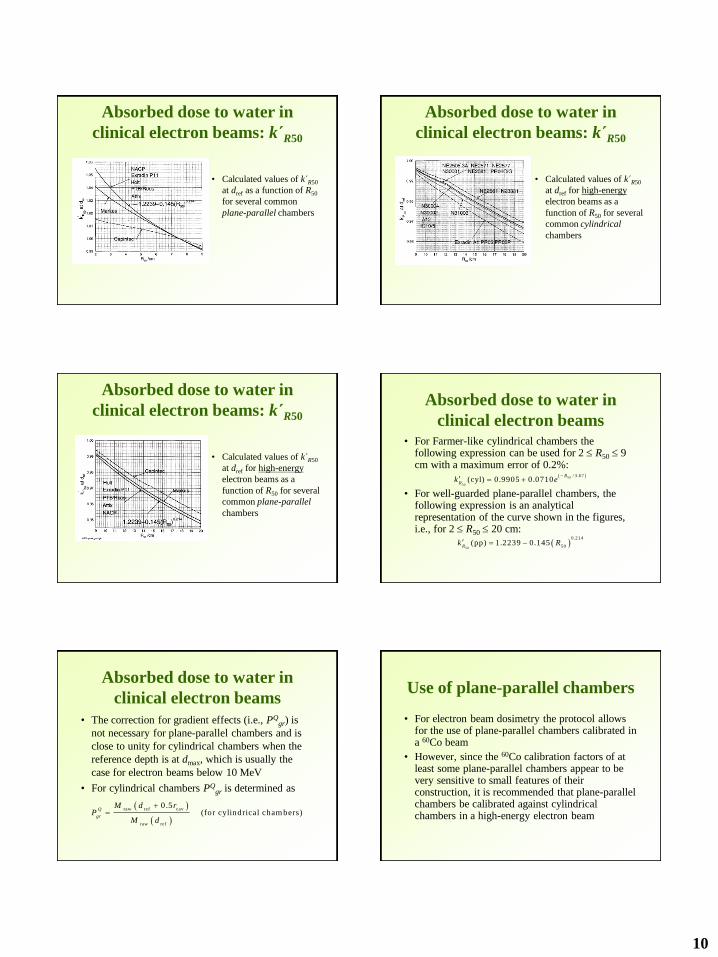
Absorbed dose to water in
clinical electron beams: k´R50
• Calculated values of k´R50
at dref as a function of R50
for several common
plane-parallel chambers
Absorbed dose to water in
clinical electron beams: k´R50
• Calculated values of k´R50
at dref for high-energy
electron beams as a
function of R50 for several
common cylindrical
chambers
Absorbed dose to water in
clinical electron beams: k´R50
• Calculated values of k´R50
at dref for high-energy
electron beams as a
function of R50 for several
common plane-parallel
chambers
Absorbed dose to water in
clinical electron beams• For Farmer-like cylindrical chambers the
following expression can be used for 2 R50 9 cm with a maximum error of 0.2%:
• For well-guarded plane-parallel chambers, the following expression is an analytical representation of the curve shown in the figures, i.e., for 2 R50 20 cm:
50
50
/ 3.67(cyl) 0.9905 0.0710
R
Rk e
50
0.214
50(pp) 1.2239 0.145
Rk R
Absorbed dose to water in
clinical electron beams
• The correction for gradient effects (i.e., PQgr) is
not necessary for plane-parallel chambers and is
close to unity for cylindrical chambers when the
reference depth is at dmax, which is usually the
case for electron beams below 10 MeV
• For cylindrical chambers PQgr is determined as
raw ref cav
raw ref
0.5 (for cylindrical cham bers)
Q
gr
M d rP
M d
Use of plane-parallel chambers
• For electron beam dosimetry the protocol allows for the use of plane-parallel chambers calibrated in a 60Co beam
• However, since the 60Co calibration factors of at least some plane-parallel chambers appear to be very sensitive to small features of their construction, it is recommended that plane-parallel chambers be calibrated against cylindrical chambers in a high-energy electron beam

11
Use of plane-parallel chambers
• After determining the beam quality and the
reference depth in the high-energy electron beam
to be used, measurements are made, in sequence,
with the point of measurement of both the
calibrated cylindrical chamber and the plane-
parallel chamber at dref
• While measuring with the cylindrical chamber,
PQgr is measured as described above
Use of plane-parallel chambers
• From these measurements the product of is
determined for the plane parallel chamber as
• Use of this product circumvents the need for obtaining the 60Co
absorbed-dose calibration factor for the plane-parallel chamber
60
50
60
50
50
cylpp
C o
ecal , pp
cylC o
ecal ,
pp (G y/C )
w
D w
R
Q
gr R D w
R
Dk N
M k
M P k k N
M k
60Co
ecal ,D wk N
Absorbed dose at dmax in
clinical electron beams
• This protocol provides the reference dose at a depth of
dref which, for higher-energy beams, will not be at dmax
where clinical normalization most often takes place
• To establish the dose at dmax one should use the
clinical percentage depth-dose data for a given beam
and determine the dose at dmax from that at dref
• Methods for measuring electron-beam percentage
depth-dose curves are given in the AAPM TG-25
protocol
Using other ion chambers
• The protocol provides kQ data for the majority of chambers
used in clinical reference dosimetry in North America
• Other cylindrical chambers can be used by finding the
closest matching chamber for which data are given
• The critical features are, in order, the wall material, the
radius of the air cavity, the presence of an aluminum
electrode, and the wall thickness
• As long as the wall material is matched and the chamber is
‘‘normal,’’ these matching data should be accurate to
within 0.5%.
Reference class ion chambers
Appendix A of the Addendum
TG-51 worksheets
The protocol provides four worksheets:
A. Photon Beams
B. Electron Beams – Cylindrical Chambers
C. for plane-parallel chambers
D. Electron Beams using Plane-Parallel
Chambers
60Co
ecal ,D wk N

12
Summary
• Ion chamber calibration: absorbed dose to water calibration factors in TG-51 protocol
• Reference conditions
• Reference dosimetry of photon beams
• Reference dosimetry of electron beams
(Gy) 60
50 ,
Co
wDecalR
Q
gr
Q
wNkkMPD
(Gy) 60
,
Co
wDQ
Q
wNMkD
General formalism
electrons
electrons
electrons
photons
QA of medical accelerators
• QA procedure for medical accelerators includes
dosimetry as its integral part
• Old protocol: TG-40
• New protocol: TG-142
– Adds recommendations for asymmetric jaws, MLC’s,
and dynamic/virtual wedge
– Separate tolerance for IMRT and SRS/SBRT machines
– Includes procedures for on-board imaging QA (planar
or cone-beam CT)