dosimetry metrology for imrt · dosimetry metrology for imrt jean m. moran, ph.d. aapm summer...
TRANSCRIPT

1
The Department of Radiation OncologyUniversity of MichiganThe Department of Radiation OncologyUniversity of Michigan
Dosimetry Metrology for IMRT
Jean M. Moran, Ph.D.Jean M. Moran, Ph.D.
AAPM Summer SchoolAAPM Summer SchoolJune 2003June 2003
JMM03 2
Outline
• Acceptance testing• Detectors for commissioning• Phantoms• Dosimetry analysis tools• Commissioning tests
– Varying complexity and geometry• Potential Pitfalls• Summary
JMM03 3
Acceptance
• Prior to purchase and installation, review manufacturer’s acceptance tests
• If needed, adapt tests and tolerances with manufacturer in purchase order
• Test basic functionality of equipment• Tests may be dependent on the MLC
design
JMM03 4
Collimator Designs
Elekta
Lower Jaws
Exit Window
Isocenter
Diaphragm
MLCUpper Jaws
Exit Window
Isocenter
Siemens
MLCLower Jaws
Upper Jaws
Exit Window
Isocenter
Varian
MLC
JMM03 5
Physical MLC Characteristics
No
31 cm
1 and 6.5 cm
Divergent
40x40 cm2
(40x27 cm2)
Siemens
No
=1 cm gap
32.5 cm
1 cm
Rounded
40x40 cm2
Elekta
YesInter -
digitation
Length
Leaf width
Leaf ends
Field
Width
16 cm (14.5 cm Carriage)
0.5 and 1 cm
Rounded
40x40 cm2
Varian
JMM03 6
Effect of Rounded Leaf Ends & Linear Motion
Uncorrected Corrected
Graves 2001
Cold
Hot
UniformCorrection
Xmlc
Xlight
Linear leaf motion
Leaf position offset = Xrad-Xlight
Xrad
2
JMM03 7
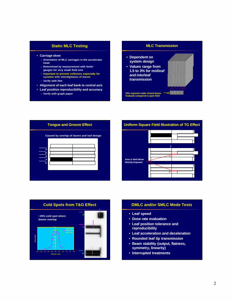
Static MLC Testing
• Carriage skew– Orientation of MLC carriages in the accelerator
head – Determined by measurement with feeler
gauges for very small field size– Important to prevent collisions especially for
systems with interdigitation of leaves
– Verify with film
• Alignment of each leaf bank to central axis• Leaf position reproducibility and accuracy
– Verify with graph paper
JMM03 8
MLC Transmission
• Dependent on system design
• Values range from 1.5 to 3% for midleafand interleaf transmission
Film exposed under closed leavesEvaluate compared to open field
JMM03 9
Tongue and Groove Effect
Caused by overlap of leaves and leaf design
JMM03 10
Uniform Square Field Illustration of TG Effect
Area in Red Never Directly Exposed
+
?
JMM03 11
Cold Spots from T&G Effect
~25% cold spot where leaves overlap
0
1 0
2 0
3 0
4 0
5 0
6 0
7 0
-2.5 -2.0 -1.5 -1.0 -0.5 0.0 0.5 1.0 1.5 2.0 2.5
Position (cm)
Dos
e (c
Gy)
square fieldsmall leaves
large leaves
JMM03 12
DMLC and/or SMLC Mode Tests
• Leaf speed• Dose rate evaluation• Leaf position tolerance and
reproducibility• Leaf acceleration and deceleration• Rounded leaf tip transmission• Beam stability (output, flatness,
symmetry, linearity)• Interrupted treatments
3
JMM03 13
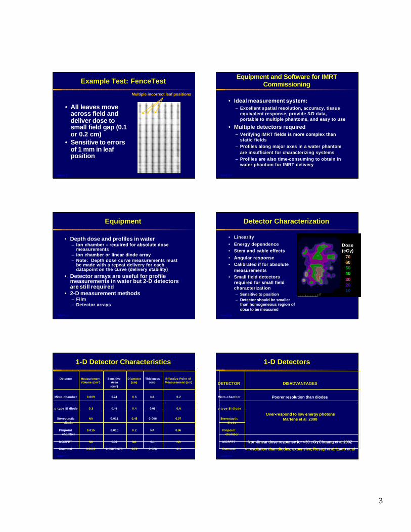
Example Test: FenceTest
• All leaves move across field and deliver dose to small field gap (0.1 or 0.2 cm)
• Sensitive to errors of 1 mm in leaf position
Multiple incorrect leaf positions
JMM03 14
Equipment and Software for IMRT Commissioning
• Ideal measurement system:– Excellent spatial resolution, accuracy, tissue
equivalent response, provide 3-D data, portable to multiple phantoms, and easy to use
• Multiple detectors required– Verifying IMRT fields is more complex than
static fields– Profiles along major axes in a water phantom
are insufficient for characterizing systems– Profiles are also time-consuming to obtain in
water phantom for IMRT delivery
JMM03 15
Equipment
• Depth dose and profiles in water– Ion chamber – required for absolute dose
measurements– Ion chamber or linear diode array– Note: Depth dose curve measurements must
be made with a repeat delivery for each datapoint on the curve (delivery stability)
• Detector arrays are useful for profile measurements in water but 2-D detectors are still required
• 2-D measurement methods– Film– Detector arrays
JMM03 16
Detector Characterization
• Linearity
• Energy dependence• Stem and cable effects
• Angular response• Calibrated if for absolute
measurements• Small field detectors
required for small field characterization– Sensitive to position– Detector should be smaller
than homogeneous region of dose to be measured
Dose (cGy)
70605040302010
JMM03 17
1-D Detector Characteristics
0.10.0260.730.056/0.0730.0019Diamond
NA0.1NA0.04NAMOSFET
0.06NA0.20.0100.015Pinpoint chamber
0.070.0060.450.011NAStereotactic diode
0.60.060.40.490.3p-type Si diode
0.2NA0.60.240.009Micro -chamber
Effective Point ofMeasurement (cm)
Thickness(cm)
Diameter(cm)
SensitiveArea(cm2 )
MeasurementVolume (cm 3)
Detector
JMM03 18
1-D Detectors
< resolution than diodes, expensive, Rustgi et al, Laub et al Diamond
Non-linear dose response for <30 cGyChuang et al 2002MOSFET
Pinpoint chamber
Stereotactic diode
Over-respond to low energy photonsMartens et al. 2000
p-type Si diode
Poorer resolution than diodesMicro -chamber
DISADVANTAGESDETECTOR

4
JMM03 19
Reader
Bias Box
MOSFET
C. Chuang, UCSF
MOSFET System
• Excellent spatial resolution
• Automatic and immediate readout
• Can be re-used immediately
• Linear dose response
• Response independent of depth
JMM03 20
-4.0
-3.0
-2.0
-1.0
0.0
1.0
2.0
3.0
4.0
0 2 4 6 8 10 12 14 16 18 20N u m b e r o f M e a s u r e m e n t s
MOSFET1 MOSFET2 MOSFET3
MOSFET Consistency
Cynthia Chuang, UCSF
JMM03 21
TLDs
• TLDs must be characterized– Time consuming
• Reusable• Achievable accuracy: 2-3%• Automatic reader required for multiple
TLD measurements
JMM03 22
TLD Holder for Phantom Measurements
D.A. Low et al. “Phantoms for IMRT Dose Distribution Measurement and Treatment Verification, Int J Radiat Oncol Biol Phys 40: 1231-1235 (1998).
JMM03 23
2-D Detectors
• Film– Radiographic: XV and EDR– Radiochromic
• Beam imaging system, CCD, SLIC, AMFPI– EPID systems attached to gantry– Investigated more for pre-treatment QA
currently
JMM03 24
Radiographic Film
• Advantages– Excellent spatial resolution
– Readily available– Less expensive than other 2-D systems
• Disadvantages– Over-response to low energies– Dependent on QA of film batch
– Dependent on processor and digitizer QA– Sensitive to storage conditions
– Need to measure the response to dose for each experiment

5
JMM03 25
XV vs EDR Film
0.0
0.5
1.0
1.5
2.0
2.5
3.0
3.5
0.0 100.0 200.0 300.0 400.0 500.0 600.0
XV2, 6 MV
XV2, 15 MV
EDR2, 6 MV
EDR2, 15 MVNet
Opt
ical
Den
sity
Dose (cGy)
Chetty and Charland “Investigation of Kodak EDR film for megavoltage photon beam dosimetry” PMB 47: 3629-3641 (2002). JMM03 26
Depth Dependence of EDR Film
0
200
400
600
800
1000
1200
1400
0 50 100 150 200 250 300 350
Dose (cGy)
Opt
ical
Den
sity
6MV-EDR2-Depth corrected6MV-EDR2-Regular
Dogan et al “Comparative evaluation of Kodak EDR2 and XV2 films for verification of intensity modulated radiation therapy,” PMB 47: 4121-4130 (2002).
JMM03 27
Radiochromic Film: Advantages
• Decreased sensitivity to low energy photons compared to radiographic film
• No processing– Film changes color with irradiation
• Insensitivity to visible light• High spatial resolution
Niroomand-Rad et al. “Radiochromic film dosimetry: recommendations ofAAPM Radiation Therapy Committee Task Group 55,” Med Phys 25: 2093-2115.
JMM03 28
Radiochromic Film: Disadvantages
• Non-uniform film response– Can be minimized by using double-exposure
technique
• Response dependent on time and temperature
• More expensive than radiographic film• Digitizer response is dependent on the
light source of the digitizer and may need to be modified
Niroomand-Rad et al. “Radiochromic film dosimetry: recommendations ofAAPM Radiation Therapy Committee Task Group 55,” Med Phys 25: 2093-2115.
JMM03 29
Active Matrix Flat Panel Dosimeter(AMFPD)
512 x 512 pixels
0.508 mm pitch
26.0 x 26.0 cm2
El-Mohri, et al. “Relative dosimetry using active matrix flat-panel imager (AMFPI) technology,” Medical Physics 26, 1999.
Preamplifiers AD converters
a-Si array
Direct Detection-No fluorescent screen
JMM03 30
Example: SMLC Delivery
AMFPD Film
184 mu600 mu/mind=10 cm
Non-commercial systemAMPFD at 10 cm depth in solid water

6
JMM03 31
Example: SMLC Delivery
B4
-4
-2
0
2
4
Pos
ition
(cm
)
-4 -2 0 2 4
Position (cm)
150
130 120
80 70 100 50 30 20
16012080400
184 mu600 mu/mind=10 cm
FilmAMFPD
JMM03 32
Gel Dosimetry: Advantages
• Obtain 3-D information in one irradiation
• Gels can be prepared with different density therefore ideal for heterogeneous measurements
• Gel can be used in containers of different shapes
• Ideal for anthropomorphic phantoms
JMM03 33
Gel Dosimetry: Disadvantages
• Sensitive to many factors such as time, preparation, temperature
• Optical reader requires cylindrical container for gel
• MR time is often limited and expensive (unless dedicated scanner)– Long scan times are required to increase
accuracy of readout– E.g. 5% accuracy over 10 hr scan time (Gum et al
2002)
• Interface of gel and container results in less accurate readout at edges of the gel
• Not ready for routine use in the communityJMM03 34
Gel Dosimetry
Gum et al. “Preliminary study on the use of an inhomogeneous anthropomorphic Fricke gel phantom and 3D magnetic resonance dosimetry for verification of IMRT treatment plans” PMB 47: N67-N77 (2002).
Slice 1
Slice 2
Slice 3
MR Dose Maps IMRT Plan MR Dose Maps- IMRT Plan
Dose % Dose Deviation %0 20 40 60 80 100 120 -60 -40 -20 0 30 40 60
JMM03 35
Considerations for Phantoms
• Fiducials for reproducible setup of phantom and detectors
• Flexibility to accommodate different detectors
• Simple vs. anthropomorphic• Homogeneous or heterogeneous
JMM03 36
Water Tank
• Restricted to gantry at 0 degrees– Unless mylar window for 90 degrees
• Flexibility in chamber position• Important for basic depth dose and
profile measurements• Output, flatness, symmetry, and
linearity assessment

7
JMM03 37
Water-equivalent Plastics
• Flat phantoms with custom chamber inserts– Accommodate film at multiple depths– Detector position only varies with depth
• Cylindrical phantoms (plastic or water filled)– Ion chamber at single position– Possibly hold films
• Can be customized to hold various detectors and have multiple positions
JMM03 38
Simple Geometric Phantom
20 cm
Van Esch et al. “Acceptance tests and QC procedures for the clinical implementation of IMRT using inverse planning and the sliding window technique: experience from five radiotherapy departments,” Radiother Oncol 65: 53- 70 (2002).
JMM03 39
IMRT Verification Phantom
D.A. Low et al. “Phantoms for IMRT Dose Distribution Measurement and Treatment Verification, Int J Radiat Oncol Biol Phys 40: 1231-1235 (1998).
JMM03 40
Calc. 1.37 GyMeas. 1.42 GyDiff –3.52%
Calc. 0.81 GyMeas. 0.78 GyDiff –3.45%
C. Chuang, UCSF
Cylindrical Phantom:Ion Chamber and MOSFETs
JMM03 41
Spiral Phantom for Dosimetric Verification
Paliwal et al “A spiral phantom for IMRT and tomotherapy treatment delivery verification” Medical Physics pp. 2503-2507 (2000).
JMM03 42
RPC Head Phantom
Target Volumes
Critical Structure
TLDs in Target VolumesRadiochromic film through multiple plansDelivery is required by RTOG for participation in IMRT trials
Removable DryInsert
Water
Water

8
JMM03 43
Anthropomorphic Phantom for Gel Dosimetry
Gum et al. “Preliminary study on the use of an inhomogeneous anthropomorphic Fricke gel phantom and 3D magnetic resonance dosimetry for verification of IMRT treatment plans” PMB 47: N67-N77 (2002).
JMM03 44
Dosimetry Analysis Software
• Transfer patient fluence maps and beam geometry to phantom geometry
• 2-D dose difference displays with colorwash
• DVHs• Highlight of differences• Gamma analysis
– % agreement and distance-to-agreement
JMM03 45
Phantom Measurements
Film at depth in water equivalent plastic
• Calculate IMRT plan for each field in measurement geometry
• Film measurement at depth for individual field at gantry=0
CalcsFilm
70 cGy60 cGy50 cGy20 cGy10 cGy
JMM03 46
Dosimetric Analysis: Overlay of Isodose Lines
Intensity Map
70 cGy60 cGy50 cGy20 cGy10 cGy
CalcsFilm
JMM03 47
Dosimetric Analysis : Dose Color Wash
CalculationIndividual Field
Film DataIndividual Field
Dose (cGy)
70605040302010
JMM03 48
Dosimetric Analysis: Dose Difference Display
Intensity Map +/- 10%
Differences due to tongue-and-groove

9
JMM03 49
Dosimetric Analysis: Dose Difference and DTA
D. A. Low – Washington University
ReferenceEvaluated
3% DoseDifference
3 mmDTA
Dose
Spatial
BothUnmod
JMM03 50
Dosimetric Analysis: Gamma Evaluation
3%/3 mm 5%/5 mm
D. A. Low – Washington University
JMM03 51
Simple Geometry Tests
• Leaf position reproducibility in dynamic or step-and-shoot mode
• Effect of gravity on leaf position accuracy and reproducibility
• Sweeping gap test• Fence test
JMM03 52
Simple Geometry Tests
• Leaf speed stability• Leaf acceleration/deceleration• Output checks for small to large fields
– Including smallest field size – 1 x 1 cm 2
• MLC limits (field size restrictions)• Depth dose curve measurements
JMM03 53
Simple Geometric Tests
JMM03 54
Geometric Tests
L. Xing et al. “Dosimetric verification of a commercial inverse treatment planning system” PMB 44: 463-478 (1999).

10
JMM03 55
Geometric Tests
Acceptance tests and quality control (QC) procedures for the clinical implementation of intensity modulated radiotherapy (IMRT) using inverse planning and the sliding window technique: experience from five radiotherapy departments Van Esch et al Radiotherapy Oncology 65: 53-70 (2002). JMM03 56
Complex Cases – Simple Geometry
Evaluate dose across field as a function of regional beamlet intensity
JMM03 57
Complex Geometry: Anthropomorphic phantom
M. A. MacKenzie et al. “Dosimetric verification of inverse planned step andshoot MLC fields from a commercial planning system,” J Appl Clin Med Phys 3: 97-109 (2002)
JMM03 58
Potential Pitfalls
• Limit number of monitor units per segment to verified Linac behavior
• Limit field width for IMRT• Overshoot-undershoot phenomenon• Incorrect tolerance value • Integration with record-and-verify
system
JMM03 59
Potential Pitfalls: Prior to Measurements
• Verify all equipment is functioning properly– Film processor, digitizer– Detectors, cables, electrometers (automatic
leakage correction)– TLD reader, ovens
• Input/output to treatment planning system• Standardize measurement setup when
possible• Monitor software and hardware changes
and QA
JMM03 60
Detector Issues
Dose (cGy)
Vol
ume

11
JMM03 61
Detector Position
• Small ion chambers are very sensitive to position
• Position should be considered with respect to MLC design– Example: CAX of Varian MLC is a junction
of four 0.5 cm wide leaves
JMM03 62
Ratio Calc/Ion Chamber - CAX
0.90
0.95
1.00
1.05
1.10
1.15
1.20
regular spike=cax spike=high spike=low
Spikiness values on part of field
Rat
io
(Cal
cula
tion/
Mea
sure
men
t)
Beam 1 Ratio 9/21/02
Beam 1 Ratio - 9/25/02 -20 segBeam 1Ratio 9/25/02 -100 segBeam 2 Ratio 9/21/02
Beam 2 Ratio 9/25/02 -20 segBeam 2 Ratio 9/25/02-100 seg
JMM03 63
Ratio Calc/Ion Chamber --0.5, -0.5 cm from CAX
SMLC Single Field 30 Fractions
0.85
0.90
0.95
1.00
1.05
1.10
1.15
1.20
regular spike=cax spike=high spike=lowSpikiness values on part of field
Rat
io (C
alcu
lati
on
/Mea
sure
men
t)
Beam 1 Ratio - Off-axis - 20 segBeam 1 Ratio off-axis - 100 segBeam 2 Ratio Off-axis - 20 segBeam 2 Ratio Off-axis-100 seg
JMM03 64
Effect of Leaf Position Offset on IMRT
Cadman et al “Dosimetric considerations for validation of a sequential IMRTProcess with a commercial treatment planning system” PMB: 3001-3010 (2002).
JMM03 65
Cadman et al “Dosimetric considerations for validation of a sequential IMRTProcess with a commercial treatment planning system” PMB: 3001-3010 (2002).
Effect of Leaf Position Offset on IMRT
No leaf offset correction-3-12% errors
With leaf offset corrected+/- 5%
JMM03 66
Overshoot Phenomenon:Example Varian System SMLC Delivery
Planned
Given
Planned
Given
Planned
Given
Ezzell and Chungbin, “The overshoot phenomenon in step -and-shoot IMRTDelivery,” J Appl Clin Med Phys 2: 138-148 (2001).

12
JMM03 67
System Communication Delay
AcceleratorControl MLC
Controller
AcceleratorControl Console
MLCWorkstation
~ 0.055 secondJMM03 68
MLC Dynamic Log File (Dynalog)
• Varian 21 EX• Expected and actual leaf positions• Beam hold-off events• Position tolerance setting • Recorded approximately every 55 ms
• Information can be compared to imported 2-D information
JMM03 69
Deviation in Leaf Trajectory
-5.0
-4.5
-4.0
-3.5
-3.0
Po
siti
on
(cm
)
1.41.21.00.80.60.40.20.0
Time (sec)
1.0
0.0Hold
Expected Trajectory Actual Trajectory MLC Beam Hold-Off
JMM03 70
DMLC: Effect of Incorporating Machine Limitations
44 mu, tolerance 0.1 mmno gap: 137 beam hold-offs
BEFORE AFTER
54 mu, tolerance 0.25 mmgap 1.1 mm: No beam hold-offs
Case1, B1
B1
JMM03 71
Summary
• Basic MLC characteristics should be tested in static mode prior to IMRT testing
• IMRT tests should be specific to delivery mode and device
• Be aware of potential issues with delivery systems that may need further investigation
• Multiple detectors and phantoms are typically required for IMRT commissioning
• Quantitative dose analysis tools are required for proper evaluation of delivery
JMM03 72
Summary
• Measurements may show dosimetric –mechanical differences that planning systems may not model at this time
• Need to know the limits of the mechanical systems and combination of software + delivery
• Continued need to improve software for delivery system, measurement devices, phantoms, and dose analysis tools
13
JMM03 73
Acknowledgements
University of MichiganDale LitzenbergJeff RadawskiTim NurushevBenedick Fraass
Dan Low – Washington UniversityCynthia Chuang - UCSF