double-block-and-bleed (dbb) valves. dbb valve · twin ball valves are commonly referred to in the...
TRANSCRIPT


Twin ball valves are commonly referred to in the oil & gas industry
as double-block-and-bleed (DBB) valves.
Most cases, when specifying these valves, the user is looking for a
valve configuration which provides a more reliable isolation than a
standard single valve would.
As a matter of fact, the actual purpose of a DBB valve is isolation
and DBB valves are used whenever the seal is critical.
For this reason, the term double-isolation-and-bleed (DIB) shall
better be used.
The differences between the two terms are not marginal particularly
when determining the functionality
the valve is expected to provide.
According to API, DBB is a ‘’feature of a valve, or valves, able to
segregate two pressure sources and to bleed/vent pressure in the
void between the two sealing elements (blocks). The bleed may be
in the pipework/pipeline when two valves are used, or in the valve
body between the two seats’’.
Thus, a DBB valve is a ‘’single valve with two seating surfaces that,
in the closed position, provides a seal against pressure from both
ends of the valve with a means of venting/bleeding the cavity
between the seating surfaces’’.
Instead, DIB is a ‘’feature of a valve or valves able to provide two
sealing elements to a single pressure source, and to bleed/vent
pressure in the void between the two sealing elements’’.
Accordingly, a DIB valve is a ‘’single valve with two seating
surfaces, each of which, in the closed position, provides a seal
against pressure from a single source with a means of venting/
bleeding the cavity between the seating surfaces’’.
A DBB valve does not achieve the same level of isolation as a DIB
one: a DBB valve separates two pressure sources, while a DIB valve
provides an additional pressure barrier that seals separately of
the main pressure barrier against a single pressure source.
The key point is that though either DBB and DIB valves can provide
single isolation in both upstream and downstream directions, i.e.
a DIB valve is DBB capable, a DBB valve does not provide positive
double isolation when only one side is under pressure.
Seating surfaces
Seating surfaces
Pressure source
Pressure source
Pressure source
Bleed valve
Bleed valve
API 6D / 6DSS / 6A / 17DTWIN BALL VALVES
For an in-depth description of the features and for more specific technical data, please check our Valve Glossary at www.hitvalve.com.
DESIGN FEATURES FLANGED FLANGELESS
API 6D/ASME B16.10 face-to-face* N/A STANDARD
Trunnion mounted STANDARD STANDARD
Floating seats STANDARD STANDARD
Independent stem and ball STANDARD STANDARD
Soft seats STANDARD STANDARD
Metal-to-metal seats OPTIONAL OPTIONAL
Full or reduced bore AS REQUESTED AS REQUESTED
Flanged Ends / Welded Ends / Hub Ends AS REQUESTED N/A
Anti-static device STANDARD STANDARD
Anti-blow-out stem STANDARD STANDARD
Stem Injection Fitting STANDARD OPTIONAL
Seat Injection Fitting OPTIONAL OPTIONAL
Seat Pocket Overlay OPTIONAL OPTIONAL
Seat Areas Overlay OPTIONAL OPTIONAL
Wetted Parts Overlay OPTIONAL OPTIONAL
Locking device open and closed positions STANDARD STANDARD
Lifting Lugs/Valve Support STANDARD STANDARD
Manual or actuated operation AS REQUESTED AS REQUESTED
Top works to ISO 5211 STANDARD STANDARD
Fire Safe Design STANDARD OPTIONAL
› In-Line Maintenance NO NO
› On-Site Maintenance YES YES
* API 6A sizes and ratings available
HB-4TWIN-BALL VALVE
208 STEM BACK-UP *
209 STEM FIRE SAFE GASKET
210 BODY COVER SEAL
211 BODY COVER BACK-UP *
212 BODY COVER FIRE SAFE GASKET
213 TRUNNION COVER SEAL
214 TRUNNION BACK-UP *
215 TRUNNION COVER FIRE SAFE GASKET
300 STEM KEY CAPSCREW
301 BODY STUD
302 BODY NUT
303 BODY COVER BOLT
304 TRUNNION COVER BOLT
305 OPERATOR MOUNTING STUD
306 OPERATOR MOUNTING NUT
343 OPERATOR FLANGE BOLT
502 PLUG
503 STEM GREASE FITTING
541 NEEDLE VALVE
* ONLY HIGH PRESSURE
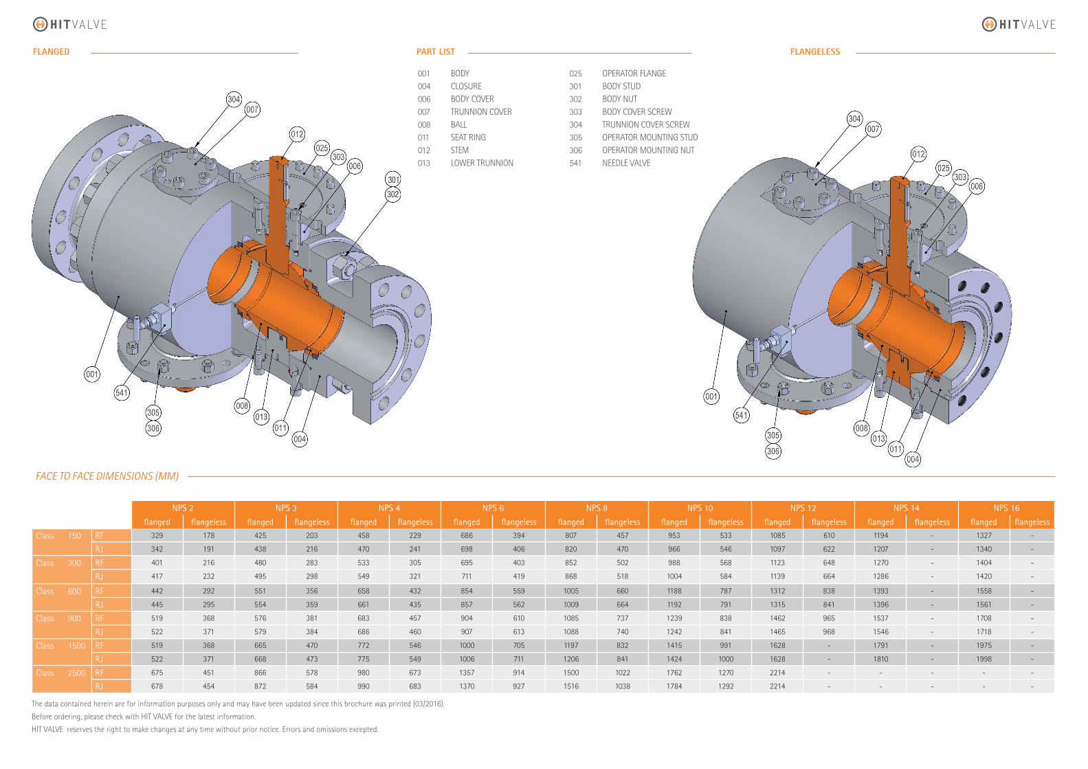
NPS 2 NPS 3 NPS 4 NPS 6 NPS 8 NPS 10 NPS 12 NPS 14 NPS 16
flanged flangeless flanged flangeless flanged flangeless flanged flangeless flanged flangeless flanged flangeless flanged flangeless flanged flangeless flanged flangeless
Class 150 RF 329 178 425 203 458 229 686 394 807 457 953 533 1085 610 1194 - 1327 -
RJ 342 191 438 216 470 241 698 406 820 470 966 546 1097 622 1207 - 1340 -
Class 300 RF 401 216 480 283 533 305 695 403 852 502 988 568 1123 648 1270 - 1404 -
RJ 417 232 495 298 549 321 711 419 868 518 1004 584 1139 664 1286 - 1420 -
Class 600 RF 442 292 551 356 658 432 854 559 1005 660 1188 787 1312 838 1393 - 1558 -
RJ 445 295 554 359 661 435 857 562 1009 664 1192 791 1315 841 1396 - 1561 -
Class 900 RF 519 368 576 381 683 457 904 610 1085 737 1239 838 1462 965 1537 - 1708 -
RJ 522 371 579 384 686 460 907 613 1088 740 1242 841 1465 968 1546 - 1718 -
Class 1500 RF 519 368 665 470 772 546 1000 705 1197 832 1415 991 1628 - 1791 - 1975 -
RJ 522 371 668 473 775 549 1006 711 1206 841 1424 1000 1628 - 1810 - 1998 -
Class 2500 RF 675 451 866 578 980 673 1357 914 1500 1022 1762 1270 2214 - - - - -
RJ 678 454 872 584 990 683 1370 927 1516 1038 1784 1292 2214 - - - - -
The data contained herein are for information purposes only and may have been updated since this brochure was printed (03/2016).
Before ordering, please check with HIT VALVE for the latest information.
HIT VALVE reserves the right to make changes at any time without prior notice. Errors and omissions excepted.
FACE TO FACE DIMENSIONS (MM)
PART LISTFLANGED FLANGELESS
001 BODY004 CLOSURE 006 BODY COVER007 TRUNNION COVER008 BALL011 SEAT RING 012 STEM013 LOWER TRUNNION
025 OPERATOR FLANGE 301 BODY STUD 302 BODY NUT 303 BODY COVER SCREW304 TRUNNION COVER SCREW305 OPERATOR MOUNTING STUD306 OPERATOR MOUNTING NUT541 NEEDLE VALVE

WWW.HITVALVE.COM
All data in this catalogue is provided specifi cally forinformation only. Due to the continuous development of our product’s, we reserve the right to update, add, change, delete and/or alter the content, in part or in whole, at our discretion. Uncontrolled when printed. Property of HIT VALVE S.p.A. Published by HIT VALVE S.p.A. Copyright © 2014
Doc. No. HIT-CAT-HB-4 - March 2016
HIT VALVE S.p.A.
Strada per Terzago, 5 I-20083 Gaggiano MI
T: +39 02 4457681F: +39 02 4456900 [email protected]