download electrical machines-iii
TRANSCRIPT
III-EEE-1st sem.-2015-16 Aurora’s Engineering College
223
7. SUBJECT DETAILS
7.5 ELECTRICAL MACHINES-III
7.5.1 Objective and Relevance
7.5.2 Scope
7.5.3 Prerequisites
7.5.4 Syllabus
i. JNTU
ii. GATE
iii. IES
7.5.5 Suggested Books
7.5.6 Websites
7.5.7 Experts’ Details
7.5.8 Journals
7.5.9 Findings and Developments
7.5.10 i. Session Plan
ii. Tutoiral Plan
7.5.11 Student Seminar Topics
7.5.12 Question Bank
i. JNTU
ii. GATE
iii. IES

III-EEE-1st sem.-2015-16 Aurora’s Engineering College
224
III-EEE-1st sem.-2015-16 Aurora’s Engineering College
225225225
7.5 ELECTRICAL MACHINES-III
7.5.1 OBJECTIVE AND RELEVANCE
The objective and relevance of this subject is to provide the student a comprehensive treatment of
synchronous machines viz. synchronous generator which is universally employed for the generation of
3-phase power at all generation stations, synchronous motors and single-phase induction motors which
are used in daily life like washing machines, fans, etc. The philosophy of the subject is to emphasize the
physical understanding of basic principles underlying the operation of electrical machines. The physical
concepts regarding the internal behaviour of electrical machines are important because these concepts
only lead to creative engineering and motivation.
This subject is an extension of previous machines courses. It deals with the detailed analysis of
Synchronous generators and motors which are the prime source of electrical power generation and its
utilities. Also concerns about the different types of single phase motors which are having significant
applications in house hold appliances and control systems.
7.5.2 SCOPE
Most of the advances in the applications and control of electric machines have taken place owing to the
break thourghs in power electronics and microprocessor based control systems. As a result, a much
broader spectrum of electric machine types are now available. Particularly permanent magnet and variable
reluctance machines are now finding many applications that are bound to increase in future. AC drives are
becoming more and more attractive in many applications, such as those requiring variable speed and
flexible control while earlier DC machines were the only choise.
7.5.3 PREREQUISITES
The knowledge of various networks theorems, theory and operation of DC and AC electrical machines are
required. Some of the basic principles from electromagnetic field and its applications are also essential to
study this subject. The subjects to be referred are network theory, electro mechanics-I and electro
mechanics-II.
7.5.4.1 JNTU SYLLABUS
UNIT-I
OBJECTIVE
The objective of this unit is to give detailed concepts on the working principle of various types of
synchronous generators with their constructional details.
SYLLABUS
SYNCHRONOUS MACHINES AND CHARACTERESTICS: Constructional features of round rotor and
salient pole machines, armature windings, integral slot and fractional slot windings, distributed and
concentrated windings, distribution pitch and winding factors, e.m.f. equation
Harmonics in generated e.m.f., suppression of harmonics, armature reaction-leakage reactance,
synchronous reactance and impedance, experimental determination, phasor diagram, load
characteristics.

226226226
III-EEE-1st Sem.-2011-12 Aurora’s Engineering College
SYLLABUS
d q
UNIT II
OBJECTIVE
The objective of this unit is to deal with the rigorious details of most useful methods to find the regulation
of cylindrical and salient pole alternators with phasor diagrams.
SYLLABUS
REGULATION OF SYNCHRONOUS GENERATOR: Regulation by synchronous impedance method,
M.M.F. method, Z.P.F. method and A.S.A. methods, salient pole alternators, two reaction analysis,
experimental determinations of X and X (Slip test), phasor diagrams, regulation of salient pole alternators.
UNIT-III
OBJECTIVE
The objective of this unit is to acquire the detail knowledge on parallel operation and load sharing of
synchronous generators and the effect of change of excitation and mechanical power input in synchronous
generators.
SYLLABUS
PARALLEL OPERATION OF SYNCHRONOUS GENERATOR: Synchronizing alternators with infinite
bus bars, synchronizing power torque, parallel operation and load sharing, effect of change of excitation
and mechanical power input, analysis of short circuit current wave form, determination of sub-transient,
transient and steady state reactances.
UNIT-IV
OBJECTIVE
The objective of this unit is to give knowledge on the basic principle of operation of synchronous motor
and the effect of excitation on armature current and power factor.
The objective of this unit is to describe the various methods of starting of synchronous motors, hunting
and its suppression in synchronous motors. This unit also gives knowledge on principle of operation
of induction generator.
SYLLABUS
SYNCHRONOUS MOTORS: Theory of operation, phasor diagram, variation of current and power
factor with excitation, synchronous condenser, and mathematical analysis for power developed
POWER CIRCLES: Excitation and power circles, hunting and its suppression, methods of starting,
synchronous induction motor.
UNIT-V
OBJECTIVE
The objective of this unit is to give fair knowledge on single phase induction motors with construction
details and analysis which are extensively used in general appliances in and around us.
The objective of this unit is to give fair knowledge on A.C series motor, basic principles on permanent
magnet and reluctance motors and their applications.

227227227
III-EEE-1st Sem.-2011-12 Aurora’s Engineering College
SINGLE PHASE MOTORS & SPECIAL MOTORS: Single phase Motors: Single phase induction
motor, constructional features, double revolving field theory, equivalent circuit, split-phase motors,
capacitor start capacitor run motors.
Principle of A.C. Series motor, universal motor, stepper motor shaded pole motor. (Qualitative Treatment
Only).
7.5.4.2 GATE SYLLABUS
UNIT–I
Synchronous generator construction features and EMF equation.
UNIT–II
Regulation of an alternator.
UNIT–III
Parallel operation of synchrnous generator.
UNIT–IV
Principle and operation of synchrnous motor, synchrnous condensers. Starting methods of synchrnous
motor.
UNIT–V
Single phase induction motor, shadded pole motor. Stepper motor.
7.5.4.3 IES SYLLABUS
UNIT–I
Synchronous generator construction features and EMF equation.
UNIT–II
Regulation of an alternator.
UNIT–III
Parallel operation of synchrnous generator.
UNIT–IV
Principle and operation of synchrnous motor, synchrnous condensers. Starting methods of synchrnous
motor.
UNIT–V
Single phase induction motor, shadded pole motor. Stepper motor.
7.5.5 SUGGESTED BOOKS
TEXT BOOKS
T1 Electric Machines, I.J. Nagrath and D.P. Kothari, 7th Edn.,Tata Mc Graw-Hill Publishshers, 2005.
T2 Electrical Machines, P.S. Bimbra, Khanna Publishers.
REFERENCE BOOKS
R1 The Performance and Design of A.C.Machines, M.G. Say, ELBS and Pitman Sons.
R2 Electric Machinery, A.E.Fitzgerald, C.Kingsley and S.Umans, 5th Edn., Mc Graw-Hill Companies, 1990.
R3 Theory of Alternating Current Machinery, Langsdorf, 2nd Edn., Tata Mc Graw-Hill.

228228228
III-EEE-1st Sem.-2011-12 Aurora’s Engineering College
R4 Electromachines-III (Synchronous and single-phase machines), S.Kamakashiah, Right Publishers.
R5 Electrical Machines, Mukerjee and Chjakravarthy, Khanna Publishers.
R6 Electrical Machines, S.K. Battacharya, Tata Mc Graw-Hill Publishers.
R7 Alternating Current Machines, E.R. RK Rajput, Laxmi Publications.
7.5.6 WEBSITES
1. www.mit.edu (massachusetts institute of technology)
2. www.soe.stanford.edu (stanford university)
3. www.grad.gatech.edu (georgia institute of technology)
4. www.gsas.harward.edu (harward university)
5. www.eng.ufl.edu (university of florida)
6. www.iitk.ac.in
7. www.iitd.ernet.in
8. www.iitb.ac.in
9. www.iitm.ac.in
10. www.iitr.ac.in
11. www.iitg.ernet.in
12. www.bits-pilani.ac.in
13. www.bitmesra.ac.in
14. www.psgtech.edu
15. www.iisc.ernet.in
16. www.ieee.org
17. www.school - for - champions.com / science / actransformers.html
18. www.onesmartclick.com / engineering / electrical - machines.html
To be prepared is half the victor y. - Miguel De Cervantes
229229229
III-EEE-1st Sem.-2011-12 Aurora’s Engineering College
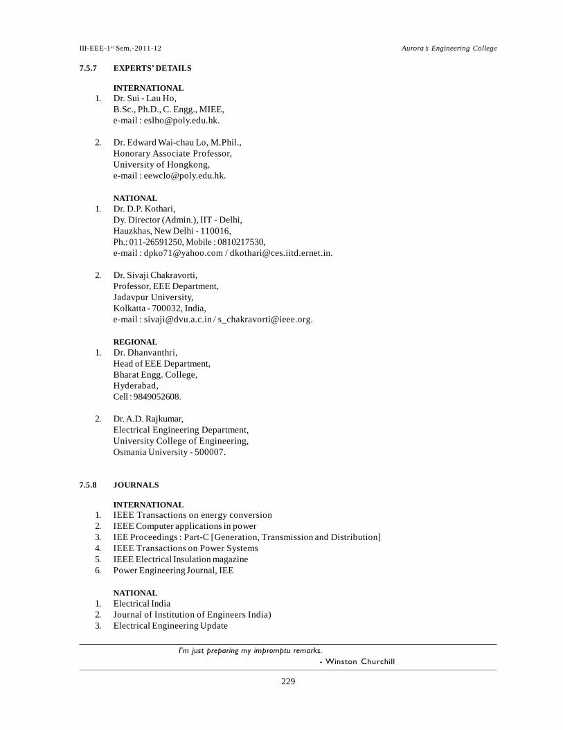
7.5.7 EXPERTS’ DETAILS
INTERNATIONAL
1. Dr. Sui - Lau Ho,
B.Sc., Ph.D., C. Engg., MIEE,
e-mail : [email protected].
2. Dr. Edward Wai-chau Lo, M.Phil.,
Honorary Associate Professor,
University of Hongkong,
e-mail : [email protected].
NATIONAL
1. Dr. D.P. Kothari,
Dy. Director (Admin.), IIT - Delhi,
Hauzkhas, New Delhi - 110016,
Ph.: 011-26591250, Mobile : 0810217530,
e-mail : [email protected] / [email protected].
2. Dr. Sivaji Chakravorti,
Professor, EEE Department,
Jadavpur University,
Kolkatta - 700032, India,
e-mail : [email protected] / [email protected].
REGIONAL
1. Dr. Dhanvanthri,
Head of EEE Department,
Bharat Engg. College,
Hyderabad,
Cell : 9849052608.
2. Dr. A.D. Rajkumar,
Electrical Engineering Department,
University College of Engineering,
Osmania University - 500007.
7.5.8 JOURNALS
INTERNATIONAL
1. IEEE Transactions on energy conversion
2. IEEE Computer applications in power
3. IEE Proceedings : Part-C [Generation, Transmission and Distribution]
4. IEEE Transactions on Power Systems
5. IEEE Electrical Insulation magazine
6. Power Engineering Journal, IEE
NATIONAL
1. Electrical India
2. Journal of Institution of Engineers India)
3. Electrical Engineering Update
I'm just preparing my impromptu remarks.
- Winston Churchill

230230230
III-EEE-1st Sem.-2011-12 Aurora’s Engineering College
7.5.10 i. SESSION PLAN
7.5.9 FINDINGS AND DEVELOPMENTS
1. Field computation for an axial flux permanent magnet synchronous generator, T.F. Chan, L.Z. Lai & S.
Xie, IEEE Transactions on Energy Conversion, Vol. 24, No. 1, March 2009.
2. Analysis and real time testing of a controlled single phase wavelet-modulated inverter for capacitor-
run induction motors, S.A. Saleh & M.A. Rahman, IEEE Transactions on Energy Conversion, Vol. 24,
No. 1, March 2009.
3. Development of a switched-reluctance motor drive with PFC front end, J.Y. Chai & C.Y. Liaw, IEEE
Transactions on Energy Conversion, Vol. 24, No. 1, March 2009.
4. Sensorless slowdown detection method for single-phase induction motors, F. Ferreyre, R. Goyet & T.
Bousccasse, IEEE Transactions on Energy Conversion, Vol. 24, No. 1, March 2009.
5. Decentralized non-linear control of wind turbine with doubly fed induction generator, F. Wu, X.P.
Zhang and P. Ju, IEEE Transactions on Power Systems, Vol. 23, No. 2, May 2008.
6. Permanent Magnet Synchronous Machine Model for Real- Time Simulation, A.B. Dehkordi, Student
Member, IEEE, A. M. Gole, Senior Member, IEEE, T. L. Maguire, Senior Member, IEEE International
Conference on Power Systems Transients (IPST'05) in Montreal, Canada on June 19-23, 2005 Paper
No. IPST05 - 159.
7. Synchro nous moto r pr otection system, Starting p rotection, synchr onization and control for
synchronous motors. www.GEDigitalEnergy.com
8. High Torque Density AC Synchronous Servo Motor, Modelling and simulation of synchronous
machine transient analysis using SIMULINK, A.Demiroren and H. L. Zeynelgil..
Web: http://www.kinavo.com
9. A Novel Protective Scheme to Protect Small-Scale Synchronous Generators Against Transient Instability
Industrial Electronics, IEEE Transactions on (Volume:60 , Issue: 4 )Date of Publication: April 2013)
10. Pattern Classification based Intelligent Numerical Protection of Salient-pole Synchronous Generator using
Neural Networks J. Electrical Systems 9-1 (2013): 125-136 © JES 2013 on-line : journal/esrgroups.org/je
11. A Novel Adaptive Loss of Excitation Protection Criterion Based on Steady-State Stability Limit Ya-dong
Liu Zeng-ping Wang Tao Zheng National Key Laboratory of New Energy Power System, North China r
University National Basic Research Program of China (2012CB215200), State Grid Cooperation chnology
Program support. 978-1-4799-2522-3/13/$31.00 ©2013 IEEE
231231231
III-EEE-1st Sem.-2011-12 Aurora’s Engineering College
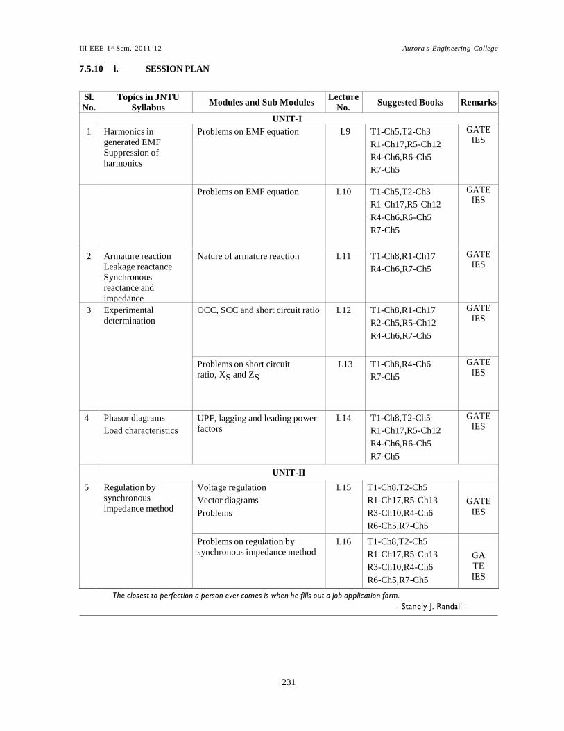
7.5.10 i. SESSION PLAN
Sl.
No. Topics in JNTU
Syllabus
Modules and Sub Modules Lecture
No.
Suggested Books
Remarks
UNIT-I
1 Harmonics in
generated EMF
Suppression of
harmonics
Problems on EMF equation L9 T1-Ch5,T2-Ch3
R1-Ch17,R5-Ch12
R4-Ch6,R6-Ch5
R7-Ch5
GATE IES
Problems on EMF equation L10 T1-Ch5,T2-Ch3
R1-Ch17,R5-Ch12
R4-Ch6,R6-Ch5
R7-Ch5
GATE IES
2 Armature reaction
Leakage reactance
Synchronous
reactance and
impedance
Nature of armature reaction L11 T1-Ch8,R1-Ch17
R4-Ch6,R7-Ch5
GATE IES
3 Experimental
determination OCC, SCC and short circuit ratio L12 T1-Ch8,R1-Ch17
R2-Ch5,R5-Ch12
R4-Ch6,R7-Ch5
GATE IES
Problems on short circuit
ratio, XS and ZS L13 T1-Ch8,R4-Ch6
R7-Ch5
GATE IES
4 Phasor diagrams
Load characteristics UPF, lagging and leading power
factors L14 T1-Ch8,T2-Ch5
R1-Ch17,R5-Ch12
R4-Ch6,R6-Ch5
R7-Ch5
GATE IES
UNIT-II
5 Regulation by
synchronous
impedance method
Voltage regulation
Vector diagrams
Problems
L15 T1-Ch8,T2-Ch5
R1-Ch17,R5-Ch13
R3-Ch10,R4-Ch6
R6-Ch5,R7-Ch5
GATE
IES
Problems on regulation by
synchronous impedance method L16 T1-Ch8,T2-Ch5
R1-Ch17,R5-Ch13
R3-Ch10,R4-Ch6
R6-Ch5,R7-Ch5
GA
TE
IES
The closest to perfection a person ever comes is when he fills out a job application form.
- Stanely J. Randall
232232232
III-EEE-1st Sem.-2011-12 Aurora’s Engineering College
Sl.
No. Topics in JNTU
Syllabus
Modules and Sub Modules Lecture
No.
Suggested Books
Remarks
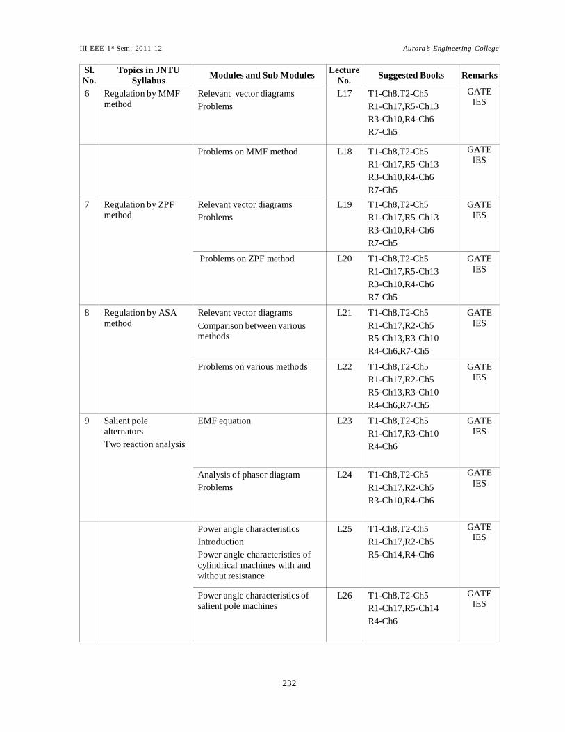
6 Regulation by MMF
method Relevant vector diagrams
Problems
L17 T1-Ch8,T2-Ch5
R1-Ch17,R5-Ch13
R3-Ch10,R4-Ch6
R7-Ch5
GATE IES
Problems on MMF method L18 T1-Ch8,T2-Ch5
R1-Ch17,R5-Ch13
R3-Ch10,R4-Ch6
R7-Ch5
GATE IES
7 Regulation by ZPF
method Relevant vector diagrams
Problems
L19 T1-Ch8,T2-Ch5
R1-Ch17,R5-Ch13
R3-Ch10,R4-Ch6
R7-Ch5
GATE
IES
Problems on ZPF method L20 T1-Ch8,T2-Ch5
R1-Ch17,R5-Ch13
R3-Ch10,R4-Ch6
R7-Ch5
GATE
IES
8 Regulation by ASA
method Relevant vector diagrams
Comparison between various methods
L21 T1-Ch8,T2-Ch5
R1-Ch17,R2-Ch5
R5-Ch13,R3-Ch10
R4-Ch6,R7-Ch5
GATE
IES
Problems on various methods L22 T1-Ch8,T2-Ch5
R1-Ch17,R2-Ch5
R5-Ch13,R3-Ch10
R4-Ch6,R7-Ch5
GATE
IES
9 Salient pole
alternators
Two reaction analysis
EMF equation L23 T1-Ch8,T2-Ch5
R1-Ch17,R3-Ch10
R4-Ch6
GATE
IES
Analysis of phasor diagram
Problems L24 T1-Ch8,T2-Ch5
R1-Ch17,R2-Ch5
R3-Ch10,R4-Ch6
GATE
IES
Power angle characteristics
Introduction
Power angle characteristics of
cylindrical machines with and
without resistance
L25 T1-Ch8,T2-Ch5
R1-Ch17,R2-Ch5
R5-Ch14,R4-Ch6
GATE IES
Power angle characteristics of
salient pole machines L26 T1-Ch8,T2-Ch5
R1-Ch17,R5-Ch14
R4-Ch6
GATE IES

233233233
III-EEE-1st Sem.-2011-12 Aurora’s Engineering College
Problems L27 T1-Ch8,T2-Ch5
R1-Ch17,R5-Ch14
R4-Ch6
GATE IES
10 Experimental
determination of Xd
and Xq (Slip test)
Phasor diagrams L28 T1-Ch8,T2-Ch5
R5-Ch13,R3-Ch10
GATE IES
Striving to better, oft we mar what's well.
- William Shakespeare

234234234
III-EEE-1st Sem.-2011-12 Aurora’s Engineering College
Sl.
No. Topics in JNTU
Syllabus
Modules and Sub Modules Lecture
No.
Suggested Books
Remarks
11 Regulation of Salient
pole alternator Regulation of salient pole
alternator L29 T2-Ch5,R4-Ch6 GATE
IES
UNIT-III
12 Synchronizing
alternators with
infinite bus bars
Synchronizing power
and torque
Synchronizing alternators with
infinite bus bars
Synchronizing power and torque
L30 T1-Ch8,T2-Ch5
R1-Ch17,R5-Ch15
R4-Ch6,R7-Ch5
GATE IES
Problems on synchronizing
power and torque L31 T2-Ch5,R1-Ch17
R4-Ch6,R7-Ch5
GATE IES
13 Parallel operation and
load sharing Parallel operation requirements
Synchronizing procedure
Synchronoscope
L32 T1-Ch8,T2 -Ch5
R1-Ch17,R2-Ch5
R5-Ch15,R3-Ch12
R4-Ch6,R6-Ch5
R7-Ch5
GATE IES
Load sharing and problems on
parallel operation L33 T1-Ch8,T2-Ch5
R1-Ch17,R5-Ch15
R4-Ch6,R6-Ch5
R7-Ch5
GATE IES
Problems on parallel operation L34 T1-Ch8,T2-Ch5
R5-Ch13,R4-Ch6
R7-Ch5
GATE IES
14 Effect of change of
excitation Operation at constant load with
variable excitation
Minimum excitation
Effect of unequal excitations on
alternators in parallel
L35 T1-Ch8,T2-Ch5
R1-Ch17,R4-Ch6
R6-Ch5,R7-Ch5
GATE
IES
15 Mechanical power
input Power flow equations
Derivation
L36 T1-Ch8,T2-Ch5
R1-Ch17,R5-Ch14
R4-Ch6
GATE
IES
16 Analysis of short-
circuit current
waveform
Determination of sub-
transient, transient
and steady state
reactance’s
Analysis of short-circuit current
waveform, determination of
sub-transient, transient and
steady state reactance’s
L37 T1-Ch8,T2-Ch5
R2-Ch6,R5-Ch13
R3-Ch10,R4-Ch6
GATE
IES
Short circuit transient in synchronous machine
L38 T1-Ch8,T2-Ch5
R2-Ch6,R5-Ch13
R3-Ch10,R4-Ch6
GA
TE
IES
Developing the plan is actually laying out the sequence of events that have to occur for you to achieve your goal.
- George L. Morrisey

235235235
III-EEE-1st Sem.-2011-12 Aurora’s Engineering College
Sl.
No. Topics in JNTU
Syllabus
Modules and Sub Modules Lecture
No.
Suggested Books
Remarks
UNIT-IV
UNIT-V
Synchronous motor
theory of operation
Phasor diagram
Characteristics
Applications
L39 T1-Ch8,T2-Ch5
R5-Ch13,R3-Ch11
R4-Ch7,R7-Ch6
GATE
IES
Variation of power
factor and current
with excitation
Synchronous
Condenser
V curves and curves
As a capacitor
As a inductor
L40 T1-Ch8,T2– Ch5
R1-Ch17,R3-Ch11
R4-Ch7,R6-Ch5
R7-Ch6
GATE
IES
Problems on synchronous motor L41 T1-Ch8,T2– Ch5
R5-Ch14,R4-Ch7
R7-Ch6
GATE
IES
25 Mathematical
Analysis for power
developed
Maximum power developed L42 T1-Ch8,R5-Ch14
R3-Ch11, R4-Ch7
GATE
IES
Problems on power developed L43 T1-Ch8,R5-Ch14
R3-Ch11, R4-Ch7 GATE
IES A good plan today is better than a perfect plan tomorrow.
- George S. Patton

236236236
III-EEE-1st Sem.-2011-12 Aurora’s Engineering College
Sl.
No. Topics in JNTU
Syllabus
Modules and Sub Modules Lecture
No.
Suggested Books
Remarks
UNIT-VI
26 Excitation and Power
circles Excitation and Power circles L44 T2-Ch5,R4-Ch7
Maximum power condition
Problems L45 T2-Ch5,R4-Ch7
27 Hunting and suppression
Methods of starting
Auxiliary motor starting
Induction motor starting L46 T1-Ch 8,T2-Ch 5
R5-Ch15,R3-Ch11
R4-Ch7,R6-Ch5
R7-Ch 6
GATE IES
28 Synchronous
induction motor Determination of equivalent
secondary current
Current diagram
L47 T2-Ch5,R4-Ch7
R7-Ch6
GATE
IES
Problems on synchronous
motors L48 T1-Ch8,T2-Ch5
R5-Ch14,R4-Ch7
R7-Ch6
GATE
IES
UNIT-VII
29 Single phase
induction motor
Constructional
features
Introduction to single phase
induction motors
Types
L49 T1-Ch10,R5-Ch20
R4-Ch8,R6-Ch6
R7-Ch4
GATE
IES
30 Double revolving
field theory Double revolving field theory L50 T1-Ch10,R5-Ch20
R3-Ch9,R4-Ch8
R6-Ch6,R7-Ch4
GATE
IES
Torque speed characteristics
(qualitative treatment and semi
quantitative treatment)
L51 T1-Ch10,R5-Ch20
R3-Ch9,R4-Ch8
R6-Ch6,R7-Ch4
GATE
IES
Problems on Equivalent Circuit L52 T1-Ch10,R5-Ch20
R3-Ch9,R4-Ch8
R6-Ch6,R7-Ch4
GATE
IES
31 Elementary idea of
cross field theory Elementary idea of cross field
theory L53 R5-Ch20,R3-Ch9
R4-Ch8,R6-Ch6
R7-Ch4
GATE
IES
32 Split phase motors Starting torque
Resistance split phase motor
Capacitance split phase motors
Problems on split phase motors
L54 T1-Ch10,R2-Ch11
R5-Ch20,R4-Ch8
R6-Ch6,R7-Ch4
GATE
IES
Problems on single phase motors L55 T1-Ch10,R2-Ch11
R5-Ch20,R4-Ch8
R6-Ch6,R7-Ch4
GATE
IES
The beginning is the most important part of the work.
- Plato

237237237
III-EEE-1st Sem.-2011-12 Aurora’s Engineering College
Sl.
No. Topics in JNTU
Syllabus
Modules and Sub Modules Lecture No.
Suggested Books
Remarks
UNIT-VIII
33 Principle and
performance of AC
series motor
Universal motor
Circuit model
Phasor diagram
Torque developed
Performance characteristics
L56 T1-Ch10,R2-Ch11
R5-Ch20,R4-Ch8
R6-Ch6,R7-Ch4
GATE
IES
34 Stepper motor Principle of working of stepper
motor L57 T1-Ch10,R2-Ch11
R5-Ch20,R4-Ch8
R6-Ch6,R7-Ch4
GATE
IES
35 Shaded pole motor Problems on single phase motors L58 T1-Ch10,R2-Ch11
R5-Ch20,R4-Ch8
R6-Ch6,R7-Ch4
GATE
IES
ii. TUTORIAL PLAN
Sl.
No.
Topics Scheduled
Salient topics to be discussed
1 Synchronous Generator
Constructional features of round rotor and salient pole
machines
Armature windings
Integral slot windings, fractional slot windings
Discussion on construction details of synchronous generator
2 Distributed windings and concentrated windings
Pitch factor, distribution factor, winding factor
EMF Equation
Problems on EMF equation
3 Harmonics in generated EMF, suppression of harmonics
Armature reaction, leakage reactance, synchronous reactance
and impedance
Experimental determination
Problems on EMF equation
4 Phasor diagrams
Load characteristics
Regulation by synchronous impedance method
Problems on EMF method
5 Regulation by MMF method
Regulation by ZPF method
Problems on MMF and ZPF method
6 Regulation by ASA method
Salient pole alternators
Two reaction analysis
Discussion on salient pole alternators
and two reaction analysis
7 Experimental determination of Xd and Xq (Slip test)
Regulation of salient pole alternator
Problems on regulation of salient pole
alternators
8 Synchronizing alternators with infinite bus bars
Synchronizing power and torque
Parallel operation and load sharing
Problems on parallel operation
When planning for a year, plant corn.When planning for a decade, plant trees.When planning for life, train and educate people.
- Chinese Proverb

238238238
III-EEE-1st Sem.-2011-12 Aurora’s Engineering College
Sl.
No.
Topics Scheduled
Salient topics to be discussed
9 Effect of change of excitation
Mechanical power input
Discussion on change of effect of
change of excitation and mechanical
power input with phasor diagrams
10 Analysis of short-circuit current waveform, determination of
sub-transient, transient and steady state reactances
Synchronous motor theory of operation, phasor diagram
Variation of power factor and current with excitation
Synchronous Condenser
Discussion on short circuit transients
in synchronous machine
Review on synchronous motor basic
operation with phasor diagrams
11 Mathematical Analysis for power developed
Excitation and Power circles
Problems on mechanical power
developed in synchronous motor,
excitation and power circles
12 Hunting and suppression
Methods of starting
Synchronous induction motor
Discussion on starting methods of
synchronous motor
13 Single phase induction motor
Constructional features
Double revolving field theory
Problems on equivalent circuit of
single phase induction motor
14 Elementary idea of cross field theory
Split phase motors
Shaded pole motor
Problems on split phase motors
15 Principle and performance of AC series motor, Universal motor
Principle of permanent magnet motor and reluctance motors
Discussion on universal motor and
stepper motors
7.5.11 STUDENT SEMINAR TOPICS
1. Industrial applications for induction motors C. Thangaraj, Dr. S.P. Srivastava and Dr. Promod Agarwal,
Eletrical India, Vol. 48, No. 3, Mar. 08.
2. Energy efficient motors for smart choice, Millind Raje, Eletrical India, Vol. 48, No. 3, Mar. 08.
3. Motor design and manufacturing aspects, JDK Patel, Eletrical India, Vol. 48, No. 3, Mar. 08.
4. Ventilation Systems of Fanless HV Motors, J.K. Patel, M.B. Kanitkar, H.V. K.Shetty,Eletrical India, Vol 47,
No.1, January 2007.
5. Electric Motor : Major Causes of Failure and Detection,Prof. V.N. Ghate and Dr. S.V. Dudul, Electrical India,
Vol 47, No. 2, Feb 07.
6. A Review of Development of Hybrid Excitation Synchronous Machine, IEEE ISIE 2005, June 20-23, 2005,
7. New Drive System with Synchronous Motor: "SANMOTION"G SANYO DENKI Technical Report No18
Nov. 2004.
8. Study and Development of Anti-Islanding Control for Synchronous Machine-Based Distributed Genera-
tors, Z. Ye GE Global Research Center Niskayuna, New York, November 2001 - March 2004.
In the consciousness of the truth he has perceived, man now sees everywhere only the awfulness or the absurdity of existence and
loathing seizes him" - Friedrich Wilhelm Nietzsche

III-EEE-1 st Sem.-2011-12 Aurora’s Engineering College
239239239
7.5.12
QUESTION BANK UNIT-I
1. Derive an expression for power developed in a non salient pole alternator. (May 11)
2. A 3 phase, 10 pole star connected alternator runs at 600 rpm. It has 120 slots with 8 conductors
per slot and conductors of each phase are connected in series. Determine the phase and line
electromotive forces if the flux per pole is 56 mWb.What harmonics due to slots might occure in the
phase and line voltages.
(May 11)
3. A 6.6 KV, 1 MVA, 3 phase alternator delivering full load at 0.8 p.f. lagging. Its reactance is 20%
and resistance negligible. By changing the excitation, the EMF is increased by 25% at this load.
Calculate the new current and power factor. The machine is connected to infinite bus bars.
(May 11)
4. The phase emf of a 3 phase, 50 Hz alternator consists of a fundamental, a 20% 3rd harmonic and a 10%
5th harmonic. The amplitude of the fundamental voltage is 1000V. Calculate the rms line voltage
when the alternators windings are in star and delta. If the reactance per phase at 50 Hz is 12
calculate the circulating current when the machine is delta connected.
(May 11)
5. i. Why is a rotating field system used in preference to a stationary field? A 6-pole alternator rotates at
1000 rpm. What is the frequency of the generated voltage?
ii. List difference between salient type and non salient type of rotor construction. (Nov 10)
6. A star connected 3 phase, 4 pole, 50 Hz alternator has a single layer winding in 24 stator slots. There
are 50 turns in each coil and the flux per pole is 0.05 Wb. Find the open circuit voltage?
(Nov 10) 7. What is armature reaction? Explain the effect of armature reaction on the terminal voltage of an
alternator at
i. u.p.f. load
ii. zero leading power factor load. Draw the relevant phasor diagrams. (Nov 10)
8. Enumerate various methods used for minimizing harmonics in turbo alternators? (June 10)
9. i. Derive the commonly used expression for power developed by synchronous motor.
ii. The input to a 11000 volts three phase star connected synchronous motor is 60 amperes. The effective
resistance and synchronous reactance per phase are 1 ohm and 30 ohms respectively. Find the power
supplied to the motor. (June 10)
10. A 11 KV, 3 phase cylindrical rotor type alternator has the following O.C.C. at rated speed
Line Voltage(V) 7300 10300 12400 14000
Field Current(A) 40 60 80 100
The excitation to produce full load current on S.C. is 34 A and when the machine supplies full load output
at 11 KV and zero p.f., the excitation is 106 A. Determine:
i. % synchronous reactance drop
ii. % leakage reactance drop
iii. The armature reaction in equivalent field amperes at full load. Neglect the armature resistance. (Nov 09)

III-EEE-1 st Sem.-2011-12 Aurora’s Engineering College
240240240
11. Explain the effect of armature reaction on the performance of an alternator. How it depends on the load
p.f.? Explain with suitable diagrams. (Nov 09)
12. Derive an expression for the induced emf in an alternator in terms of terminal voltage, p.f and armature
parameters from the phasor diagram. (Nov 09)
13. Draw and explain the phasor diagram of a salient pole synchronous generator supplying a lagging p.f.
load? (Nov 09)
14. i. Explain the leakage reactance and armature reactance of an alternator.
ii. A 3 -, star connected alternator is rated 1600KVA, 13500V. The effective armature resistance and reactance
are 1.5 /ph and 30 Ù/ph respectively. Calculate the percentage regulation for a load of 1280KW at a
power factor of a. 0.8 leading b. 0.8 lagging. (Nov 09)
15. Explain the effect of armature reaction on the EMF induced. Is it possible to obtain load voltage more than
EMF inducted? If yes, how? (Nov 09, 07)
16. Find the rms value of fundamental and third harmonic EMF per phase for an alternator having the following
data. 50Hz, 3, 20poles, 4 slot / pole / phase, double layer winding with 6 conductors / slot, coil span of
1500 electrical, the fundamental flux per pole is 0.1wb and third harmonic is 17% of fundamental. All coils
of a phase are connected in series. (Nov 09, 08)
17. i. What are harmonics? Explain the sources of harmonics. What are the various effects of harmonics on
generated emf in an alternator?
ii. In a 50KVA, star connected, 440v, 3-, 50Hz alternator, the effective armature resistance is 0.25/ph, the
leakage reactance is 0.5/ph. Determine the following at rated load and power factor
a. Internal emf
b. No load.s emf
c. Value of synchronous reactance which replaces armature reaction. (Nov 09)
18. i. What is armature reaction? Explain how it affects the performance of an alternator for different power
factors of load.
ii. The OC and SC test data for a 500KVA, 1100V, 50Hz, star connected synchronous generator are 1280v
between lines on open circuit with a field current of 8A and 380A on short circuit with same field current.
When a DC voltage of 5v was applied to two of its terminals, a current of 25A was measured. Find the
value of synchronous impedance and synchronous reactance. (Nov 09)
19. i. Explain de-magnetising, cross magnetising & magnetising nature of armature reaction.
ii. Calculate the RMS value of the induced EMF per phase of a 4 pole, 3-, 50 Hz, alternator with 3 slots per
pole per phase and 6 conductors per slot in two layers. The coil span is 1500. The flux per pole has a
fundamental component of 0.2 wb & a 16 % third harmonic component. (May 09)
20. i. Explain with neat diagram, the various tests to be conducted on an alternator to obtain its synchronous
reactance.
ii. Find the synchronous impedance and reactance in an alternator in which a given field current produces an
armature current of 250 A on short circuit nad generates an open circuit voltage of 1500 volts. The
effective armature resistance is 0.5 /ph. Hence calculate the terminal PD when a load of 250 A 6600 V at
a power factor of 0.8 lagging is switched off potential difference. (May 09)
21. i. Explain the operation and effect of load power factor on the performance of alternator.
ii. The effective resistance of a 2200 V, 50 Hz, 440 kVA, single phase alternator is 0.5 . On short circuit, a field
current of 4 A gives the full load current. The EMF on open circuit for the same field current is 1160 V. Find
Synchronous impedance, Synchronous reactance and % regulation of 0.6p.f lagging. (May 09)
III-EEE-1 st Sem.-2011-12 Aurora’s Engineering College
241241241
V DC
OC SC f DC DC
V OC SC
DC
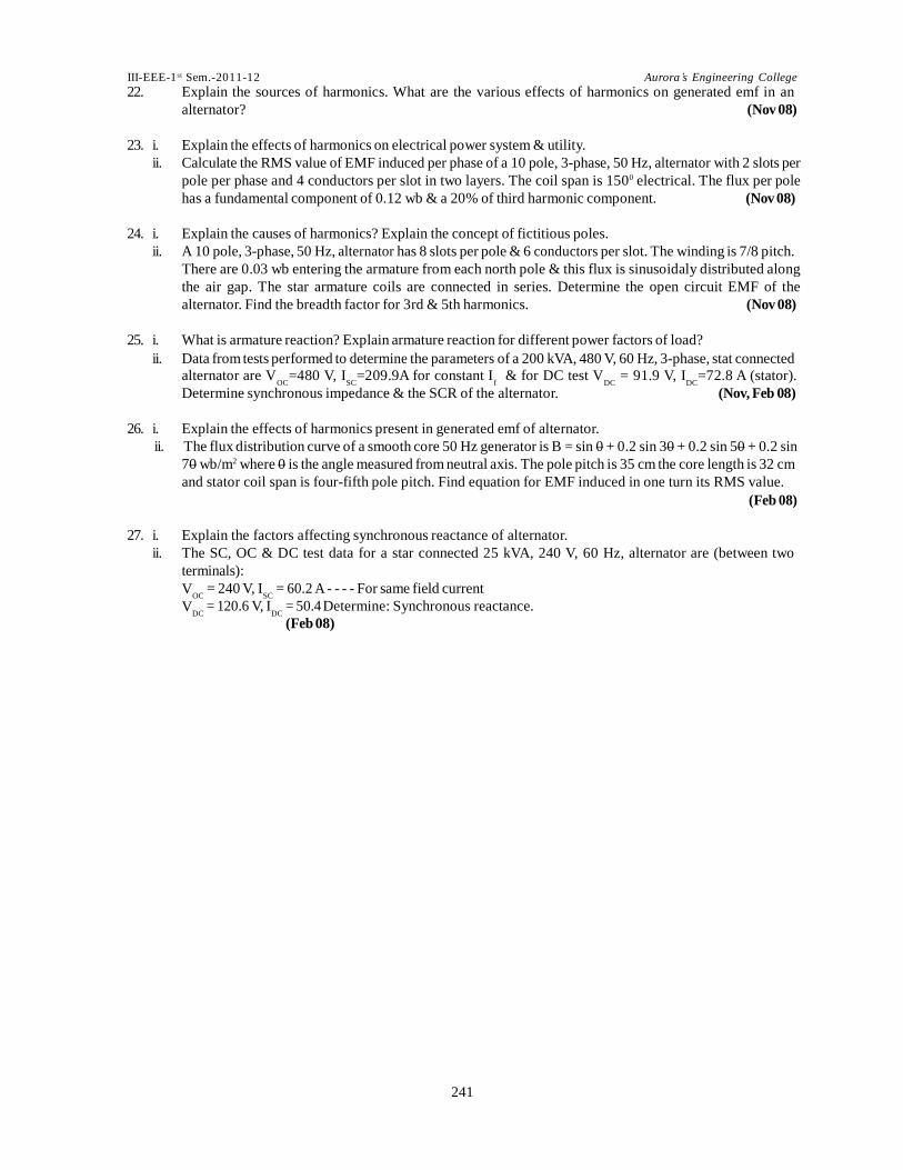
22. Explain the sources of harmonics. What are the various effects of harmonics on generated emf in an
alternator? (Nov 08)
23. i. Explain the effects of harmonics on electrical power system & utility.
ii. Calculate the RMS value of EMF induced per phase of a 10 pole, 3-phase, 50 Hz, alternator with 2 slots per
pole per phase and 4 conductors per slot in two layers. The coil span is 1500 electrical. The flux per pole
has a fundamental component of 0.12 wb & a 20% of third harmonic component. (Nov 08)
24. i. Explain the causes of harmonics? Explain the concept of fictitious poles.
ii. A 10 pole, 3-phase, 50 Hz, alternator has 8 slots per pole & 6 conductors per slot. The winding is 7/8 pitch.
There are 0.03 wb entering the armature from each north pole & this flux is sinusoidaly distributed along
the air gap. The star armature coils are connected in series. Determine the open circuit EMF of the
alternator. Find the breadth factor for 3rd & 5th harmonics. (Nov 08)
25. i. What is armature reaction? Explain armature reaction for different power factors of load?
ii. Data from tests performed to determine the parameters of a 200 kVA, 480 V, 60 Hz, 3-phase, stat connected
alternator are V =480 V, I =209.9A for constant I & for DC test V = 91.9 V, I =72.8 A (stator).
Determine synchronous impedance & the SCR of the alternator. (Nov, Feb 08)
26. i. Explain the effects of harmonics present in generated emf of alternator.
ii. The flux distribution curve of a smooth core 50 Hz generator is B = sin 0 + 0.2 sin 30 + 0.2 sin 50 + 0.2 sin
70 wb/m2 where 0 is the angle measured from neutral axis. The pole pitch is 35 cm the core length is 32 cm
and stator coil span is four-fifth pole pitch. Find equation for EMF induced in one turn its RMS value.
(Feb 08)
27. i. Explain the factors affecting synchronous reactance of alternator.
ii. The SC, OC & DC test data for a star connected 25 kVA, 240 V, 60 Hz, alternator are (between two
terminals):
= 240 V, I = 60.2 A - - - - For same field current
= 120.6 V, I = 50.4 Determine: Synchronous reactance.
(Feb 08)

III-EEE-1 st Sem.-2011-12 Aurora’s Engineering College
242242242
28. i. Explain the characteristics and nature of harmonics present in generated emf of alternator?
ii. The flux density distribution in the air gap of an alternator is B = B sin 0 + B sin 30 + B sin 50 wb/m2, where 1 3 5
B = 0.3B & B = 0.2B . The total flux per pole is 0.08 wb. The coil span is 80% of pole pitch. Find the RMS 3 1 5 1
value of EMF induced in single turn machine. (Feb 08)
29. i. Explain the load characteristics of an alternator.
ii. The phase EMF of a 3-phase alternator consist of fundamental, 20 % 3rd harmonic & 10 % fifth harmonic.
The amplitude of fundamental is 1000 V. Calculate the RMS value of line & phase voltage, when the
alternator is connected in
a. Star b. Delta (Nov 07)
30. Justify the statement ‘The terminal voltage of an alternator is not only depends on the load current, but
also on the nature of load’. (Nov 07)
31. A 200 kVA, 480 V, 50 Hz, star connected synchronous generator with a rated field current of 5A was tested
and the following data were obtained:
OC test: 540 V between lines on open circuit.
SC test: 300 A.
When a DC voltage of 10 V was applied to two of its terminals, a current of 25 A was measured, find the
value of synchronous impedance, synchronous reactance voltage regulation of 0.6 p.f leading.
(Nov 07)
32. i. A 16 pole, 3-phase star connected alternator has 144 slots. The coils are short pitched by one slot. The flux
per pole is phase = 100 sin 0 + 30 sin 30 + 20 sin 50. Find the harmonics as percentage of phase voltage &
line voltage.
ii. Define
a. synchronous reactance b. synchronous impedance and c. leakage reactance in an alternator.
33. What is armature reaction? How it is accounted as a reactance drop? (Feb 07)
34. What is armature reaction? Explain the effect of armature reaction on the terminal voltage of an alternator
at
i. Unity power factor load
ii. Zero lagging power factor load
iii. Zero leading power factor load. Draw the relevant phasor diagram. (Feb 07, May 05, Nov 03)
35. What is synchronous reactance? How do you calculate synchronous impedance experimentally?
(Feb07, Nov 03)
36. Draw and explain the phasor diagram of an alternator at lagging power factor (Nov 06)
37. A 3-phase, 50 hz cylindrical rotor synchronous machine has the following parameters.
Self inductance per phase = 3.15 mH
Armature leakage inductance = 0.35 mH for this machine, calculate the mutual inductance between armature
phases and its synchronous reactance. (Nov 06, May 04)
38. With neat circuit diagrams, explain the various tests conducted on an alternator to determine its
synchronous reactance. (Mar 06)
39. Describe armature reaction and explain its effect on terminal voltage. (Nov 05)
40. What are slot harmonics and how they are suppressed. (Nov 05, 04)
41. Discuss how synchrnous impedance of alternator can be determined. (Nov 05)
42. Explain the effect of harmonics on pitch and distribution factors. (May 05)

III-EEE-1 st Sem.-2011-12 Aurora’s Engineering College
243243243
As the old proverb says "Like readily consor ts with like."
- Cicero

III-EEE-1 st Sem.-2011-12 Aurora’s Engineering College
244244244
f
f
sc
43. What are the causes of harmonics in the voltage and current waveforms of electrical machinery and what
means are taken in design to reduce them? (May 05)
44. An alternator has 18 slots/pole and the first coil lies in slots 1 and 16. Calculate the pitch factor for
i. Fundamental
ii. 3rd harmonics
iii. 5th harmonics and
iv. 7th harmonics. (May 05)
45. Calculate the speed and open –circuit line and phase voltages of a 4-pole, 3-phase, 50HZ, star-connected
alternator with 36 slots and 30 conductors per slot. The flux per pole is 0.0496 Wb and is sinusoidally
distributed. (Nov 04)
46. Determine their values for a 3-phase winding with 4 slots per pole per phase, the coil span being 10 slot
pitches. Calculate the percentage increase in R.M.S. Value of the phase voltage due to a 25% third harmonic.
(Nov 04)
47. i. Discuss the effect of armature reaction in an alternator.
ii. A 3.3 KV, 3-phase, star connected alternator has full-load current of 100A. Under short circuit condition
it takes 5A filed current to produce full-load short circuit current. The emf on open circuit for the same
excitation is 900V (line to line). The armature resistance is 0.9 Ohm per phase. Determine synchronous
reactance per phase. (Nov 04)
48. i. Describe the method of finding synchronous impedance of a given alternator.
ii. The following data is obtained for 100KVA, 1100V, 3-phase alternator
D.C. resistance test between lines = 10V
Current in line = 10 A.
Line circuit test; field current I = 12 A.
Line voltage = 420V;
Short circuit test; I = 12 A.
Line current L = rated value
Calculate synchronous impedance (Nov 04)
49. Explain about harmonics generated in e.m.f. of a synchronous machine. How do you suppress them?
What are the problems due to harmonics. (Nov 04)
50. Explain the effect of armature reaction on terminal voltage of an alternator at i. u.p.f. ii. zero p.f. load. Draw
the relevant phasor diagrams. What is leakage reactance? (Nov 04, 03)
51. i. Explain how open circuit and short circuit tests are conducted on a synchronous machine.
ii. What is an air-gap line? In an alternator, explain why short circuit characteristic is a straight line where as
open circuit characteristic is a curve. (May 04)
52. A 3-Phase star connected, 4-pole, 50 Hz., alternator develops an open circuit voltage of 12.5 KV for an
applied field voltage of 400 V. For a field circuit resistance of 10 Ohms, Calculate the amplitude of armature
to field mutal inductance. (May 04)
53. Draw and explain the phasor diagram of alternator under loaded conditions. (Nov 03)
54. Discuss open circuit and short circuit characteristics of a synchronous generator.
Draw the phasor diagram under short circuit condition. What do you understand by the term “short
circuit ration”? Discuss how short circuit ratio can be calculated from the two characteristic curves?
(Nov 02, IES 00)
Get not your fr iends by bare compliments , but by giving them sensible tokens of your love.
- Socrates

III-EEE-1 st Sem.-2011-12 Aurora’s Engineering College
250250250
55. A synchronous generator is feeding a zero power factor (lagging) load at rated current. The
armature reaction is
i. magnetizing
ii. demagnetizing
iii. cross-magnetizing
iv. ineffective (GATE 06)
56. The resultant flux density in the air gap of a synchronous generator is the lowest
during. i. open circuit
ii. solid short
circuit iii. full load
iv. half load (IES 06)
57. Sketch and explain the open circuit and short circuit characteristics of a synchronous machine (IES 97)
58a) Discuss briefly the load characteristics of alternator for different power factors. b) The effective resistance of a 2200 V, 50 Hz, 440 KVA, 1-phase alternator is 0.5Ω On short circuit, a field
current of 40 A gives the full-load current of 220 A. The voltage on open-circuit with same filed
excitation is 1160 V, Calculate
i) Synchronous impedance ii) Synchronous reactance. ]
2.a) What is the effect of harmonics and how do you supress
How do you determine synchronous reactance and impedance experimentally? Draw the load
characteristics of an alternator. [8+8]
UNIT-II
1. From the following test results, determine the voltage regulation of a 2000V, single phase
alternator delivering a current of 100A at:
i. unity p.f.
ii. 0.8 leading
p. iii. 0.71 lagging
p.f. Test results:
Full load current of 100A is produced on short circuit by a field excitation of 2.5A, an emf of 500V
is produced on open circuit by the same excitation. The armature resistance is 0.8 ohms. (May 11)
2. The effective resistance of a 1200 KVA, 3.3KV, 50Hz, 3 phase star connected alternator is 0.25 /
phase. A field current of 35A produces a current of 200A on short circuit and 1.1KV (line to line) on
open circuit. Calculate the power angle and p.u. change in magnitude of the terminal voltage when
the full load of 1200KVA at 0.8 p.f. (lag) is thrown off. Draw the corresponding phasor diagram.
(May 11) 3. A 3 phase, 4 pole, star connected turbo alternator has a cylindrical rotor. The reactance per phase of
winding is 2.5 and resistance per phase is 0.15. The alternator has a terminal potential di”erence
of 6600 V when delivering a current of 250A. Calculate
i. The generated emf at 0.6 p.f lagging
ii. The regulation at 0.8 p.f lagging. (May 11, Nov 09)
4. The following test results are obtained from a 3 phase, 6000 KVA, 6600V, star connected, 2 pole, 50
Hz turbo alternator: With a field current of 125A, the open circuit voltage is 8000V at the rated
speed; with the same field current and rated speed the short circuit current is 800A. At the rated full
load, the resistance drop is 3%. Find the regulation of alternator on full load and at a p.f. of 0.8
lagging.
(May 11)

III-EEE-1 st Sem.-2011-12 Aurora’s Engineering College
251251251
5. A 1000KVA, 6.6KV, 3 phase star connected synchronous generator has a synchronous reactance of
25 per phase with negligible resistance. It supplies full load current at 0.8 p.f. lagging and at
rated terminal voltage. Compute the terminal voltage for the same excitation when the generator
supplies full load current at 0.8 p.f. leading.
(Nov 10)
6. Sketch and explain the O.C. and S.C. characteristics of a synchronous machine. How voltage
regulation can be calculated by the use of their results?
(Nov 10)
7. A 1200 KVA, 6600V, 3 phase star connected alternator has its armature resistance as 0.25 per phase
and its synchronous reactance as 5 per phase. Calculate its regulation if it delivers a full load at 0.8
lagging and 0.8 leading p.f. (Nov 10)
8. A 11KV, 3 phase, star connected synchronous generator delivers 4000 KVA at unity power factor
when running on constant voltage constant frequency bus bars. If the excitation raised by 20%,
determine the KVA and power factor at which the machine now works. The steam supply is constant
and the synchronous reactance is 30! per phase. Neglect the power losses and assume the magnetic
circuit to be un saturated? (Nov 10)
9. A straight line connects terminal voltage and load of a 3 phase star connected alternator delivering
current at 0.8 p.f. lagging. At no load the terminal voltage is 3500V and at full load of 2280KW, it is
3300V. Calculate the terminal voltage when delivering current to a 3 phase star connected load having
a resistance of 8and a reactance of 6 per phase. Assume constant speed and field excitation.
(Nov 10)
10. The O.C.C. of a 10 MVA, 6.6KV, 3 phase star connected alternator is given by the following data:
And the full load z.p.f. characteristic is given by:
Assuming the leakage reactance to be 15% and ignoring resistance, determine the excitation required
for full load, normal voltage at a p.f. of 0.8 lagging. (Nov 10)
11. i. Compare the results obtained for voltage regulation by emf, mmf, zpf, ASA and saturated synchronous
method.
ii. A 3 phase 17.32KVA, 400V, star connected alternator is delivering rated load at 400V and at p.f. 0.8lag.
Its synchronous impedance is 0.2 + j2 per phase. Find the load angle at which it is operating.
(June 10)
12. Explain the synchronous impedance method of determining the voltage regulation of an alternator?
Comment on the merits and limitations of this method. Why is this method considered as pessimistic
method? (June 10)
13. Describe the slip test method for the measurement of Xd and Xq of synchronous machine?
(June 10)
14. A 400V, 50kVA, 50Hz, star connected alternator has the armature effective resistance of 0.1 ohm per phase.
An excitation of 2.5A produces on open circuit emf of 130V (line). The same excitation produces a current
of 90A on short circuit.
Calculate:
i. The synchronous impedance and reactance;
ii. The full load regulation of alternator for:
a. 0.866 lagging p.f b. unity p.f. (Nov 09)
15. A 30kVA, 440V, 50 Hz, star connected synchronous generator gave the following test data:
III-EEE-1 st Sem.-2011-12 Aurora’s Engineering College
252252252
f
OL
f
OL
OL
OL
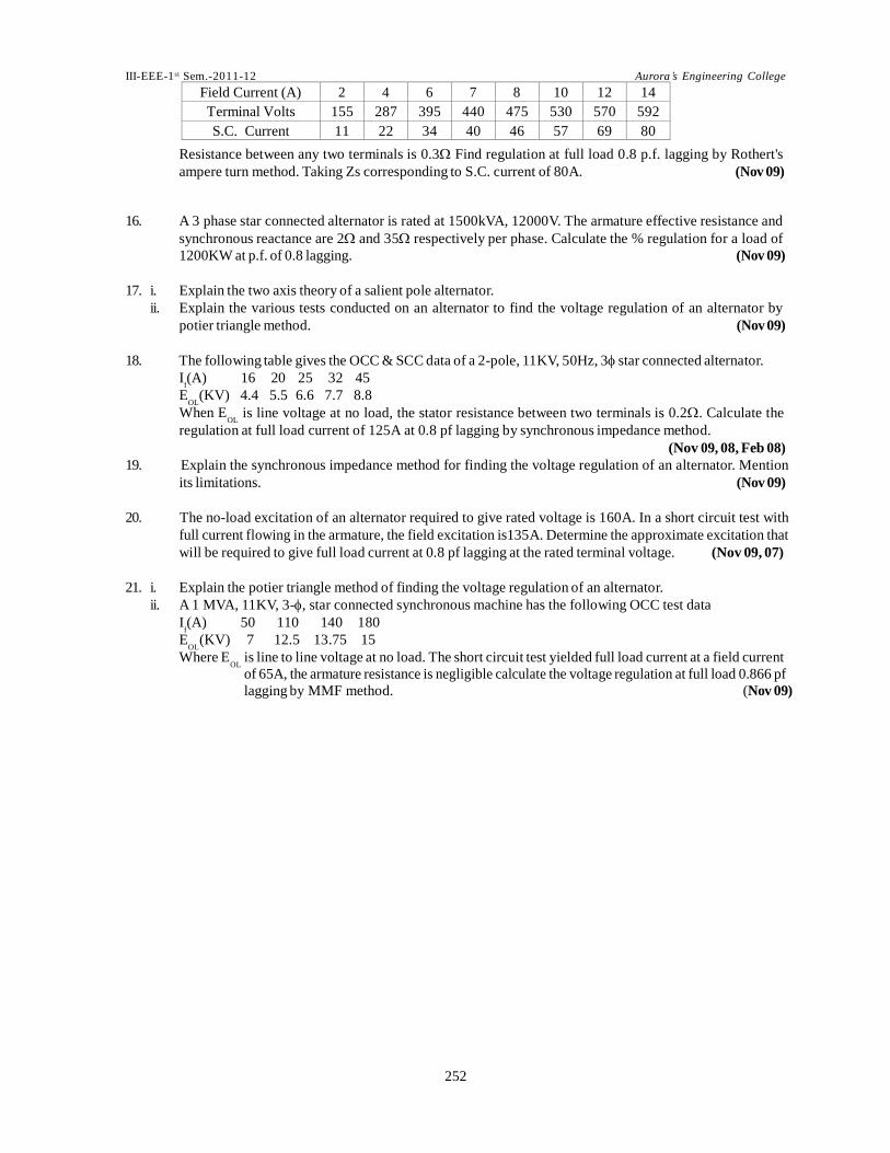
Field Current (A) 2 4 6 7 8 10 12 14 Terminal Volts 155 287 395 440 475 530 570 592 S.C. Current 11 22 34 40 46 57 69 80
Resistance between any two terminals is 0.3 Find regulation at full load 0.8 p.f. lagging by Rothert's
ampere turn method. Taking Zs corresponding to S.C. current of 80A. (Nov 09)
16. A 3 phase star connected alternator is rated at 1500kVA, 12000V. The armature effective resistance and
synchronous reactance are 2 and 35 respectively per phase. Calculate the % regulation for a load of
1200KW at p.f. of 0.8 lagging. (Nov 09)
17. i. Explain the two axis theory of a salient pole alternator.
ii. Explain the various tests conducted on an alternator to find the voltage regulation of an alternator by
potier triangle method. (Nov 09)
18. The following table gives the OCC & SCC data of a 2-pole, 11KV, 50Hz, 3 star connected alternator.
I (A) 16 20 25 32 45
E (KV) 4.4 5.5 6.6 7.7 8.8
When E is line voltage at no load, the stator resistance between two terminals is 0.2. Calculate the
regulation at full load current of 125A at 0.8 pf lagging by synchronous impedance method.
(Nov 09, 08, Feb 08)
19. Explain the synchronous impedance method for finding the voltage regulation of an alternator. Mention
its limitations. (Nov 09)
20. The no-load excitation of an alternator required to give rated voltage is 160A. In a short circuit test with
full current flowing in the armature, the field excitation is135A. Determine the approximate excitation that
will be required to give full load current at 0.8 pf lagging at the rated terminal voltage. (Nov 09, 07)
21. i. Explain the potier triangle method of finding the voltage regulation of an alternator.
ii. A 1 MVA, 11KV, 3-, star connected synchronous machine has the following OCC test data
I (A) 50 110 140 180
E (KV) 7 12.5 13.75 15
Where E is line to line voltage at no load. The short circuit test yielded full load current at a field current
of 65A, the armature resistance is negligible calculate the voltage regulation at full load 0.866 pf
lagging by MMF method. (Nov 09)

III-EEE-1 st Sem.-2011-12 Aurora’s Engineering College
253253253
22. i. Explain the Roher’s AT method of finding voltage regulation.
ii. A 1 MVA, 6.6 kV, 3-phase star connected synchronous generator has a synchronous reactance of 25 ohms
per phase. It supplies full load current at 0.8 lagging pf and a rated terminal voltage. Compute the terminal
voltage for the same excitation when the generator supplies full load current at 0.8 leading pf.
(May 09, Nov, Feb 08)
23. A 3-, 200 kVA, 1.1 kV, 50 Hz star connected alternator having an effective per phase resistance of 0.62
gave the following results:
Field Current (A) 20 35 50 80 100 120 OC Voltage VL 692.8 1120 1450 1750 1953 2180 SC Current (A) 0 22 44 66 88 110
Using MMF method, find the voltage regulation at 100 A
i. 0.8 pf lagging
ii. 0.8 pf leading. (May 09, Nov 07)
24. i. Explain the various tests to be conducted on an alternator to find the voltage regulation of an alternator.
ii. Explain the effect of ‘Saturation’ on the performance of an alternator. How the effect of saturation can be
overcome in calculation. (May 09)
25. i. Explain the various tests conducted on an alternator to find the voltage regulation of an alternator by
Potier triangle method.
ii. The no load excitation of an alternator required to give rated voltage is 1 pu. In a short circuit test with full
current flowing in the armature, the field excitation was 0.85 pu. Determine the approximate excitation that
will be required to give full load current at 0.78 PF leading at the rated terminal voltage. (Nov 08)
26. What is the synchronous impedance method? Why the method is called so? What are the limitations of
this theory? (Nov, Feb 08)
27. i. Explain the ‘Zero power factor’ method of finding voltage regulation of an alternator.
ii. The no load excitation of an alternator required to give rated voltage is 1 pu. In a short circuit test with full
current flowing in the armature, the field excitation was 0.75 pu. Determine the approximate excitation that
will be required to give full load current at 0.866 PF lagging at the rated terminal voltage. (Nov 08)
28. i. How the MMF method is different from EMF method in finding voltage regulation of an alternator?
Explain the drawbacks of each method.
ii. A 1 MVA, 11 kV, 3-phase, star connected synchronous machine has following OCC test data:
(where EOL is the line voltage at no load)
The short circuit test yielded full load current at a field current of 60 A. The ZPF yielded a full load current
at terminal voltage for a field current of 150 A. The armature resistance is negligible. Calculate the voltage
regulation at full load 0.866 pf lagging by Potier triangle method. (Feb 08)
29. A 3-phase, 440 V, 50 Hz, delta connected alternator has direct axis & quadrature axis reactance of 0.12 ohms
and 0.09 ohms respectively. If the alternator supplies 900 A at 0.8pf lagging, calculate the following:
i. the excitation EMF, neglecting saliency (Xd = Xq)
ii. the excitation EMF, taking into account the saliency.
Neglect armature resistance. (Feb 08)

III-EEE-1 st Sem.-2011-12 Aurora’s Engineering College
254254254
30. i. Explain the voltage regulation method of an alternator by which the armature reaction & leakage reactance
can be separated.
ii. A 3-phase, star connected salient pole synchronous generator is driven at a speed near synchronous with
the field circuit open and the stator is supplied from a balanced 3-phase supply. Voltmeter connected
across the line gave minimum and maximum readings of 1196 V & 1217 Volts. The line current fluctuated
between 120 & 225 Amp. Find the direct and quadrature axis reactances per phase. Neglect armature
resistances. (Nov 07)
31. With proper explanation & diagram, Justify the statement ‘MMF method for finding voltage regulation is
optimistic and EMF method for finding voltage regulation is pessimistic’. (Nov 07)
32. i. Derive an expression for finding regulation of salient - pole alternator using two reaction theory . Draw its
Phasor diagram. (Feb 07, Nov 06)
ii. A generator rated at 25 MVA, 0.8 pf lag, 13.8 kV, 3- phase is operating at normal terminal voltage and rated
load . The direct axis synchronous reactance is 7.62, Quadrature axis synchronous reactance is 4.57 and
the armature resistance is 0.15/ph. Determine the direct axis and quadrature axis components of armature
current and internal induced voltage. Also find the regulation. (Feb 07)

III-EEE-1 st Sem.-2011-12 Aurora’s Engineering College
255255255
33. i. Explain why synchronous-impedance method of computing the voltage regulation leads to a pessimistic
value at lagging power factor loads.
ii. The open and short - circuit test readings for
Field Amps: 10 20 25 30 40 50
O.C.Terminal V 800 1500 1760 2000 2350 2600
S.C.armature current in A: - 200 250 300 - -
The armature effective resistance is 0.2 per phase. Draw the characteristic curves and estimate the full-
load percentage regulation at
a. 0.8 p.f.lagging b. 0.8 p.f. leading. (Feb 07, Nov 06)
34. i. Explain the two reaction theory applicable to salient pole synchronous Machine.
ii. A 4500 KVA,50 Hz,3-phase,synchronous generator having a synchronous reactance of 0.3 p.u. is running
at 1500 r.p.m and is excited to give 11000 V.If the rotor deviates slightly from its equilibrium position, what
is the synchronizing torque in N-m per degree mechanical displacement. (Feb 07)
35. i. Explain the terms direct axis synchrnous reactance and quadrature axis synchronous reactance of a
salient pole alternator. On what factors do these values depend?
ii. A 3 MVA, 6 ple alternator runs at 1000 rpm in parallel with other machines on 3.3 KV bus bars. The
synchrnous reactance is 20%. Calculate the synchronizing power per one mechanical degree of
displacement and the corresponding synchrnonizing torque when the alternator as supplying full load at
0.8 lag p.f. (Feb 07, Mar 06, 05)
36. i. What is voltage regulation? Discuss the synchronous impedance method of calculating voltage regula-
tion.
ii. A 500V, 50KVA, 1-phase alternator has an effective resistance of 0.2, field current of 10A produces an
armature current of 200A on short circuit and an emf of 450V on open circuit. Calculate
a. Synchronous impedance and reactance b. Full-load regulation with 0.8p.f. lagging.
(Feb 07, Nov 06, 05, May 05)
37. i. Explain the potier - triangle method of determining the voltage regulation of an alternator.
ii. A 3-phase star-connected alternator is rated at 1600KVA and 13,5000V. The armature effect resistance and
synchronous reactance per phase are 1.5 and 30 respectively. Calculate the percentage regulation for
a load of 1280KW at p.f of
a. 0.8 lagging b. unity c. 0.8 lead (Feb, Nov 07, Nov 05)
38. i. What happens to the value of synchronous reactance if air gap is increased.
ii. A 30KVA, 440V, 50Hz, 3-Phase, Star-connected alternator gave the following test data:
Field Current (A) 2 4 6 7 8 10 12 14
Terminal Voltage (V) 155 287 395 440 475 530 570 592
S.C. Current (A) 11 22 34 40 46 57 69 80
Resistance between any two terminals is 0.3 Ohms. Find the regulation at full load, 0.8 p.f. lagging, by
MMF method (Feb 07, Nov 03)
39. Explain how the Potier triangle can be drawn with the help of O.C.C and any two points on the Z.P.f curve
and also explain the Potier reactance method of determining regulation of an alternator. (Nov 06)
40. A 2000 KVA, 11KV, 3-phase, star connected alternator has a resistance of 0.3 ohm and reactance of 5 ohm
per phase It delivers full-load current at 0.8 lagging p.f at rated voltage. Compute the terminal voltage for
the same excitation and load current at 0.8 p.f leading. (Nov 06)
"To introduce something altogether new would mean to begin all over, to become ignorant again, and to run the old, old risk of
failing to learn." - Isaac Asimov

III-EEE-1 st Sem.-2011-12 Aurora’s Engineering College
256256256
d a
d q
q
41. i. What is an infinite bus? State the characteristics of an infinite bus. What are the operating characteristics
of an alternator connected to an infinite bus?
ii. A 3 MVA,6-pole alternator runs at 1000 r.p.m in parallel with other machines on 3.3 KV bus-bars. The
synchronous reactance is 20%.Calculate the synchronizing power per one mechanical degree of
displacement and the corresponding synchronizing torque. (Nov 06)
42. i. Decribe the slip test method for the measurement of X to X of synchronous machines.
ii. A 3.5 MVA, slow-speed, 3-phase synchrnous generator rated at 6.6 KV has 32 poles its direct and quadrature
axis synchronous reactances as measured by the slip test atre 9.6 ohm and 6 ohm respectively. Neglecting
armature, determine the regulation and the excitation emf needed to maintain 6.6 KV at the terminals when
supplying a load of 2.5 MW at 0.8 pf lagging. What maximum power can the generator supply at the rated
terminal voltage, if the field becomes open-circuited? (Nov, Mar 06, May, Nov 05)
43. i. Develop the expression for finding regulation of salient pole alternator using two-reaction theory. Draw
its phasor diagram.
ii. A 3-phase, star-connected, 50 Hz synchronous generator has direct-axis synchronous reactance of 0.6
pu. and quadrature axis synchronous reactance of 0.45 p.u. The generation delivers rated KVA at rated
voltage. Drw the phasor diagram at full-load 0.8 p.f. Lagging and hence calculate the open circuit volage
and voltage regulation. Resistive drop at full-load is 0.015 p.u. (Nov, Mar 06)
44. Explain the factors responsible for making terminal voltage of an alternator less than the induced voltage.
(Mar 06)
45. i. Explain the MMF method of determining the voltage regulation of alternator.
ii. A 1000KVA, 11000V 3-phase, 50 Hz, star-connected turbo-generator has an effective resistance of 2ohm/
phase. The O.C.C. and zero p.f. full load data is as follows:
O.C. Voltage (V) 5805 7000 12550 13755 15000
Field current (A) 40 50 110 140 180
T V at F.L. Zero p.f 0 1500 8500 10500 12400
Estimate the % regulation for F.L. at 0.8 p.f lagging. (Mar 06)
46. Sketch and explain the open-circuit and short circuit characteristics of a synchronous machine. How
voltage regulation can be calculated by the use of their results. (Mar 06, Nov 04, 02)
47. A 3-phase star connected alternator is rated at 1600KVA, 13,500 V. The armature effective resistance and
synchronous reactance are 1.5 ohm and 30 ohm respectively per phase. Calculate the percentage regulation
for a load of 1280 KW at power factors of
a. 0.8 leading and
b. 0.8 lagging. (Mar 06)
48. Draw the phasor diagram of an alternator corresponding to zero full load regulation. (Mar 06, Nov 03)
49. i. Explain how regulation is determined from slip test.
ii. A 3-phase salient pole synchronous generator has X =0.8 p.u; X
full-load at 0.8 p.f. Lagging at rated terminal voltage. Computer
a. Power angle and
= 0.5 p.u and R =0 generator supplies
b. No-load voltage if excitation remains constant. (Nov 05)
Just do what you do best.
- Red Auerbach

III-EEE-1 st Sem.-2011-12 Aurora’s Engineering College
257257257
I f
I f
50. i. Discuss about two reaction theory with relevant phasor diagram.
ii. A 4 pole, 50 Hz, 22 KV, 500 MVa synchronous generator having a synchronous reactance of 1.57 pu is
feeding into a power system, which can be represented by a 22 KV infinite bus in series with a reactance
of 0.4. The generator excitation is continually adjusted (by means of an automatic voltage regulator) so
as to maintain a terminal voltage of 22 KV independent of the load on the generator.
a. Draw the phasor diagram, when the generator is feeding 250 MVA into the power system. Calculate the
generator current, its power factor and real power fed by it. What is the excitation emf of the generator.
(Nov 05)
51. Define and explain the terms synchronous impedance and voltage regulation of an alternator. State the
assumptions made in the synchronous impedance method. (Nov 05)
52. A 3-phase, 50 Hz, star-connected, 2000KVA, 23000V alternator gives a short circuit current of 600A for a
certain field excitation. With the same excitation, the O.C. Voltage was 900 V. The resistance between a pair
of terminal was 0.12. Find full-load regulation at
a. u.p.f
b. 0.8 p.f lagging
c. 0.8 p.f leading. (Nov 05, Nov 04, 02)
53. i. Develop the expression for finding voltage regulation of salient-pole alternator.
ii. The no-load and full-load zero power factor characteristics for a 23.5MVA, 13.8 KV, 3-phase, star-connected
turbo-generator are given below in per unit values: No-load characterstics
No-load characterstics
0.10 0.20 0.40 0.60 0.80 1.0 1.2 1.4 1.6 2.0 2.5
V 0.13 0.23 0.45 0.69 0.87 1.0 1.09 1.15 1.21 1.28 1.36
Zero power factor characterstics
1.2 1.3 1.4 1.6 1.8 2.0 2.2 2.4 2.6
V 0.015 0.13 0.25 0.49 0.69 0.83 0.92 0.99 1.04
Determine the regulation at full-load, 0.8 p.f lag by the zero p.f method. Neglect armature resistance.
(Nov 05)
54. i. Define voltage regulation of an alternator. Explain the various factors, which may affect the regulation of
an alternator.
ii. A 100-KVA, 3000V, 50Hz, 3-phase, star –connected alternator has effective armature resistance of 0.2. The
field current of 40A produces short-circuit current of 200A and an open-circuit emf of 1040V(line value).
Calculate the full-load voltage regulation at 0.8 p.f.lagging and 0.8 p.f.leading. Draw phasor diagrams.
(Nov 04, 03, 02)
55. i. Explain the method of determining the voltage regulation of an alternator by ASA method.
ii. An alternator has a synchronous reactance of 20% and negligible resistance calculate its voltage regulation
when working at full load.
a. 0.8 P.f Lag b. Unity P.f and c. 0.8 P.f. Lead (Nov 04, 03)
56. i. Explain the two reaction theory applicable to salient pole synchronous Machine.
ii. A 6.6 kV, 1MVA, 3ø alternator is delivering full load at 0.8 p.f. lagging. Its reactance is 20% and resistance is
negligible. By changing the excitation, the e.m.f. is increased by 25% at this load. Calculate the new current
and the power factor. The machine is connected to infinite bus-bars. (Nov 04)
57. i. Describe synchronous impedance method to determine regulation of an alternator for Lagging power
factor.
ii. A 600V, 60KVA, Single-phase alternator has an effective resistance of 0.2 Ohms. A field current of 10A
produces an armature current of 210A on short circuit and an e.m.f. of 480V on open circuit calcute.
a. Synchronous impedance and reactance.
b. Regulation with 0.8 P.f Lagging and unity P.f. leading (Nov 04, 03, 02)
Natural abilities are like natural plants; they need pruning by study.
- Francis Bacon

III-EEE-1 st Sem.-2011-12 Aurora’s Engineering College
258258258
F
V OC
58. What are the precautions to be taken while conducting Slip test? Draw the Phasor diagram when the load
connected is of Leading p.f. (May 04)
59. The following data was obtained for the OCC of a 10MVA, 13KV, 3 Phase, 50 hz, Star connected synchronous
generator.
I (A) 50 75 100 125 10 162.5 200 250 300
(Line)(KV) 6.2 8.7 10.5 11.8 12.8 13.2 14.2 15.2 15.9
An excitation of 100A causes the full load current to flow during the short circuit test. The excitation
required giving the rated current at zero p.f. and rated voltage is 290A.
i. Calculate the synchronous reactance of the machine.
ii. Calculate the leakage reactance of the machine assuming the resistance to be negligible.
iii. Determine the excitation required when the machine supplies full load at 0.8 P.f Lagging by using the
leakage reactance and drawing the MMF Phasor diagram. What is the voltage regulation of the machine?
(Nov 03)
60. A 1000 KVA, 11000V, 3 Phase star connected alternator has an effective resistance of 2 Ohms/Phase. The
characteristics on Open – circuits and with full load current at zero P.f. and the open circuit core losses are:
Field Current (A) 40 50 110 140 180
OC teminal Voltage (V) — 7000 12500 13750 15000
Core loss (KW) — 7.5 16.6 22.4 33.5
Saturation curve zero P.f (V) 0 — 8500 10500 12400
Deduce by the Z.P.f method.
i. The percentage regulation for full load at a Lagging 0.8 P.f. Find also.
ii. The efficiency at this load, given that the field current has resistance of 0.5 Ohms and that the mechanical
and additional losses amount to 10 KW. (Nov 03, 02)
61. A 600KVA, 3300V, 8 pole, 3 Phase, 50 Hz alternator has the following characteristics.
Amp-turns/pole 4000 5000 7000 10000
Terminal EMF 2850 3400 3850 4000
There are 200 conductors in series per phase. Find the SC characteristics, the field ampere-turns for full
load 0.8 P.f (lagging) and the voltage regulation, having given that the inductive drop at full load is 7% and
that the equivalent armature reaction in amp-turns per pole= 1.06 X ampere conductor per phase per pole.
(Nov 03)
62. Explain the Phasor diagram of salient pole synchronous machine
i. At Lagging P.f.
ii. At Leading P.f. (Nov 03)
63. i. Explain the A.S.A. method of predetermining the regulation of an alternator.
Note: You need not explain how to conduct the tests necessary for this method but take the test results.
ii. The open and short circuit test date on a 3 phase, 1 MVA, 3.6 KV, star connected synchronous generator
is given below:
Field Current (Amps) 60 70 80 90 100 110
Voc (line) volts 2560 3000 3360 3600 3800 3960
S.C. Test (Amp.) 180 - - - - -
Find the unsaturated synchronous reactance, the adjusted synchronous reactance and the short circuit
ratio. (Nov 03)
64.
Explain Potier triangle method of finding regulation of an alternator.
(Nov 02)
I have learnt that I am me, that I can do the things that, as one might put it, me can do, but I cannot do the things that me would
like to do. - Agatha Christie
III-EEE-1 st Sem.-2011-12 Aurora’s Engineering College
259259259
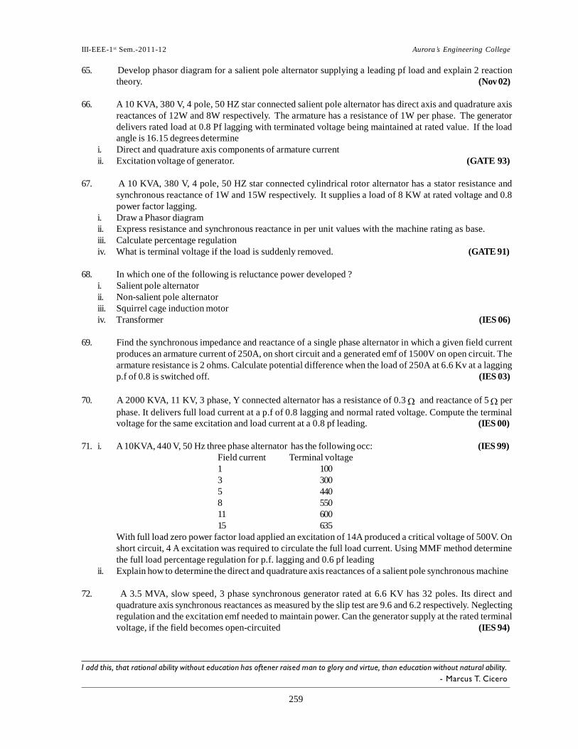
65. Develop phasor diagram for a salient pole alternator supplying a leading pf load and explain 2 reaction
theory. (Nov 02)
66. A 10 KVA, 380 V, 4 pole, 50 HZ star connected salient pole alternator has direct axis and quadrature axis
reactances of 12W and 8W respectively. The armature has a resistance of 1W per phase. The generator
delivers rated load at 0.8 Pf lagging with terminated voltage being maintained at rated value. If the load
angle is 16.15 degrees determine
i. Direct and quadrature axis components of armature current
ii. Excitation voltage of generator. (GATE 93)
67. A 10 KVA, 380 V, 4 pole, 50 HZ star connected cylindrical rotor alternator has a stator resistance and
synchronous reactance of 1W and 15W respectively. It supplies a load of 8 KW at rated voltage and 0.8
power factor lagging.
i. Draw a Phasor diagram
ii. Express resistance and synchronous reactance in per unit values with the machine rating as base.
iii. Calculate percentage regulation
iv. What is terminal voltage if the load is suddenly removed. (GATE 91)
68. In which one of the following is reluctance power developed ?
i. Salient pole alternator
ii. Non-salient pole alternator
iii. Squirrel cage induction motor
iv. Transformer (IES 06)
69. Find the synchronous impedance and reactance of a single phase alternator in which a given field current
produces an armature current of 250A, on short circuit and a generated emf of 1500V on open circuit. The
armature resistance is 2 ohms. Calculate potential difference when the load of 250A at 6.6 Kv at a lagging
p.f of 0.8 is switched off. (IES 03)
70. A 2000 KVA, 11 KV, 3 phase, Y connected alternator has a resistance of 0.3 and reactance of 5 per
phase. It delivers full load current at a p.f of 0.8 lagging and normal rated voltage. Compute the terminal
voltage for the same excitation and load current at a 0.8 pf leading. (IES 00)
71. i. A 10KVA, 440 V, 50 Hz three phase alternator has the following occ: (IES 99)
Field current Terminal voltage
1 100
3 300
5 440
8 550
11 600
15 635
With full load zero power factor load applied an excitation of 14A produced a critical voltage of 500V. On
short circuit, 4 A excitation was required to circulate the full load current. Using MMF method determine
the full load percentage regulation for p.f. lagging and 0.6 pf leading
ii. Explain how to determine the direct and quadrature axis reactances of a salient pole synchronous machine
72. A 3.5 MVA, slow speed, 3 phase synchronous generator rated at 6.6 KV has 32 poles. Its direct and
quadrature axis synchronous reactances as measured by the slip test are 9.6 and 6.2 respectively. Neglecting
regulation and the excitation emf needed to maintain power. Can the generator supply at the rated terminal
voltage, if the field becomes open-circuited (IES 94)
I add this, that rational ability without education has oftener raised man to glory and virtue, than education without natural ability.
- Marcus T. Cicero

III-EEE-1 st Sem.-2011-12 Aurora’s Engineering College
260260260
73. i. A 10 KVA, 440 V, 50 Hz, 3 phase alternator has the following O.C.C
Field current (amp) 1.5 3.0 5.0 8.0 11.0 15.0
Terminal voltage (volts) 150 300 440 550 600 635
With full load zero p.f load applied; an excitation of 14A produced a terminal voltage of 500V on the short
circuit, 4A excitation was required to circulate full load current. Using MMF method determine the full load
percentage regulation for 0.8 pf lagging and 0.8 pf leading
ii. When three phase supply is given to a three phase winding, a rotating magnetic field of constant amplitude
will be produced. Justify the above statement. (IES 93)
74. A 3 ph star connected synchronous generator is rated at 1.5 MVA, 11 KV. The armature effective resistance
and synchronous reactance are 1.2 and 25 respectively per phase. Calculate the percentage voltage
regulation for a load of 1.4375 MVA.
i. 0.8 pf lagging
ii. 0.8 pf leading.
Also find out the pf at which the regulation becomes zero (IES 92)
75. In an alternator, a lagging current weakens the main field but in a synchronous motor it strengthens the
main field. Explain why?
(IES 92)
76.a) Discuss the Potier method of predetermining the regulation of an alternator.
b) 3 phase star connected alternator is rated at 1800 KVA, 11 KV. The armature effective resistance and
synchronous reactance are 1.4 Ω and 28 Ω respectively per phase. Calculate the percentage regulation for a load of 1250 KW at p.f. 0.8
lag. [8+8]
77.a) Explain the Z.P.F method for finding the regulation of an alternator. b) In a single phase alternator, a voltage of 50 V is generated in O.C test and current of 200A is flowing in S.C
test at same field current and the armature resistance is
0.1 ohm. Calculate the synchronous reactance and impedance, generated voltage and voltage regulation
when it supplies a current of 100 A at 200 V, 0.8 p.f.
lagging. [8+8]
UNIT-III
1. What are the effects of hunting on the performance of synchronous motor and explain the method of
suppressing the hunting. (May 11)
2. i. State the conditions necessary for paralleling alternators?
ii. A 500 MVA, 3 phase, 6 pole, and 11 KV star connected alternator is running in parallel with other
synchronous machine on 11000 V bus. The synchronous reactance of the machine is 5 per phase.
Calculate the synchronizing power per mechanical degree at full load and 0.8 p.f. lagging. (May 11) 3. What do you mean by synchronizing alternators? Describe any one method of synchronizing?
(May 11, 10) 4. i. Derive an expression for the reactive power output from the terminals of a cylindrical rotor alternator.
ii. A 3 phase, 20MVA, 11KV, star connected alternator has Zs = 1 + j8 per phase. Determine the max.
reactive power that can be delivered by this alternator for an excitation voltage of 14KV.
(Nov 10) 5. Describe a method of synchronizing 3 phase synchronous machine to the infinite bus bars using two
bright one dark lamp method with relevant circuit diagram. (Nov 10)
6. Two exactly similar 3000 KVA synchronous generators operate in parallel. The governor of the first
machine is such that the frequency drops uniformly from 50 Hz on load to 48 Hz on full load. The
corresponding uniform speed drop of second machine is from 50 Hz to 47.5 Hz.
III-EEE-1 st Sem.-2011-12 Aurora’s Engineering College
261261261
i. How will the two machines share a load of 5000 KW?
7.
ii. What is the max. load at u.p.f. that can be delivered without overloading either machine? (Nov 10)
Explain why prime movers driving alternators operating in parallel should have drooping speed load characteristics? (June 10)
8. Describe briefly the effect of varying excitation upon armature current and power factor of
synchronous motor when input power to the motor is maintained constant. (June 10)
9. A synchronous generator is connected to an infinite bus. Discuss with the help of phasor diagrams
i. Effect of changing excitation at constant mechanical input
ii. Effect of changing the input at constant excitation. (June 10)
10. Describe the method of synchronizing the 3 phase alternator to the infinite bus giving the relevant
circuit diagram. (June 10)
11. Explain the following:
i. Why bright lamp of synchronizing is preferred over dark lamp method.
ii. How do synchronizing lamps indicate the phase variation of the incoming machine and running machine.
(Nov 09)
12. Two exactly similar 3000 KVA synchronous generators operate in parallel. The governor of the first
machine is such that the frequency drops uniformly from 50 Hz on load to 48 Hz on full load. The
corresponding uniform speed drop of second machine is from 50 Hz to 47.5 Hz.
i. How will the two machines share a load of 5000 KW?
ii. What is the max. load at u.p.f. that can be delivered without overloading either machine? (Nov 09)
13. Two 15 KVA, 400V, 3 phase alternators in parallel supply a total load of 25KVA at 0.8 p.f. lagging. If one
alternator shares half the power at u.p.f. determine the p.f. and KVA shared by the other alternator.
(Nov 09, 05, 04)
14. Show that an alternator running in parallel on constant voltage and frequency bus bars has a natural time
period of oscillation. Deduce a formula for the time of one complete oscillation and calculate its value for
a 5000 KVA, 3 phase, and 10000V machine running at 1500 rpm on constant 50 Hz bus bars. The moment
of inertia if the whole moving system is 14,112 Kg-m2 and the steady S.C. current is five times the normal
full load value. (Nov 09, May 04)
15. i. Explain the operation of an alternator on infinite busbars with varying steam supply?
ii. Two alternators are working in parallel supplying a lighting load of 300KW and a motor load of 5MW at
0.866 pf lagging. One machine is loaded up to 5MW, at 0.9 pf lagging. What is the load and power factor
of other machine? (Nov 09)
16. i. Why parallel operation of alternators is necessary? What are the advantages of connecting alternators in
parallel? Mention all necessary conditions for successful parallel operation of alternators.
ii. A 25MVA, 6.6KV, 50Hz, 4 pole alternator has pu, armature resistance of 0.004 and synchronous reactance
of 0.67pu, when the machine is supplying rated current at rated voltage, the induced EMF is 1.5pu. Find
the torque angle and load power factor. (Nov 09)
17. Explain, how alternators working in parallel share a load if their electrical speeds are not same. (Nov 09)
18. A 5MVA, 10KV, 1500rpm,3-, 50Hz alternator is operating on infinite bus bar. Find synchronizing power
per mechanical degree of angular displacement at
i. No-load
ii. Full-load at rated voltage and 0.8pf lagging. (Nov 09, Feb 08)
19. Explain the effect of change in excitation on the parallel operation of two alternators. (Nov 09, 08)

III-EEE-1 st Sem.-2011-12 Aurora’s Engineering College
262262262
20. Two identical 3MVA alternators are running in parallel. The frequency drops from no load to full load for
the two alternators are 50Hz to 47 Hz and 50Hz to 48Hz respectively.
i. How will they share a load of 4000KW?
ii. What is maximum load they can share at unity power factor without overloading any alternator?
(Nov 09)
Aptitude found in the understanding and is often inherited. Genius coming from reason and imagination, rarely.
- Samuel Taylor Coleridge

III-EEE-1 st Sem.-2011-12 Aurora’s Engineering College
263263263
s
21. i. A 2 MVA, 8 pole, 3-, alternator is connected to 6000 V, 50 Hz bus bars & has a synchronous reactance of
4 /ph. Calculate the synchronizing power & synchronizing torque per mechanical degree of rotor
displacement at no load. Assume normal excitation.
ii. Explain the effect of damper winding & field winding on the transient behavior of an alternator. How the
effect of these two can be minimised? (May 09)
22. i. Explain the various methods of synchronization of alternators.
ii. Two similar 4 MVA alternators operate in parallel. The governor of first machine is such that frequency
drops from 50 Hz at no load to 47.5 Hz at full load. The corresponding drop for second machine is 50 Hz to
48 Hz.
a. How will they share a load of 6 MW?
b. What is the maximum load they can share at UPF without over loading any generator?(May 09, Nov 08)
23. i. Why parallel operation of alternators is necessary? What are the advantages of connecting alternators in
parallel?
ii. A 5 MVA, 10kV, 1500 RPM, 3-, 50 Hz alternator is opening on infinite bus bar. Find synchronizing power
per mechanical degree of angular displacement at:
a. No load
b. Full load at rated voltage & 0.8 power factor lagging. Also find synchronizing torque for a 0.50 mechanical
displacement in each case. x =20%. (May 09)
24. i. Explain all the necessary conditions for successful parallel operation of alternators.
ii. A 2 MVA, 3-, star connected, 4 pole, 750 RPM alternator is operating on 6000 V bus bars, Xs is 6/ph.
Find synchronizing power and torque for full load 0.8 power factor lagging. (May 09, Nov 07)
25. i. Explain the operational differences in parallel operation of two alternators & synchroning an alternator to
infinite bus bars.
ii. Two star connected alternators supply a load of 3 MW at 0.8 pf lagging and share the load equally. The
excitation of second machine is adjusted so that it is supplying 150 A at a lagging pf. The synchronous
impedances are 0.4 + j12 /ph& 0.5 + j10 /ph. Find current, power factor, induced EMF and load angle of
each machine. Terminal voltage is 6.6 kV. (Nov 08)
26. i. Explain the term synchronization, and hence explain, synchronizing power.
ii. Two identical 3 MVA alternators are running in parallel. The frequency drops from no load to full load for
the two alternators are 50 Hz to 47 Hz and 50 Hz to 48 Hz respectively.
a. How they will share a load of 4000 kW?
b. What is maximum unity factor load which they can supply jointly supply without any one of them over
loaded? (Nov 08)
27. Two similar stat connected alternators 3-phase alternators share a load of 7500 kW equally at 6000 V and
0.8 pf lagging. The synchronous impedance of 2.5 + j50 /ph. The excitation of second machine is
changed, so that it delivers 40 A at a lagging pf. Find:
i. Armature current of first machine
ii. EMF of each machine
iii. Power factor of each machine. (Nov 08)
28. A 2 pole, 50 Hz, 3-phase turbo alternator is excited to generate a bus-bar voltage of 11 kV on no load. The
machine is star connected and the short circuit current for this excitation is 1000 A. Calculate the
synchronizing power per degree of mechanical displacement of the rotor and the corresponding
synchronizing torque. (Nov 08)
Ability is sexless.
- Christabel Pankhurst

III-EEE-1 st Sem.-2011-12 Aurora’s Engineering College
260260260
29. i. Explain the ‘two bright one dark’ & ‘all dark’ method of synchronization of alternators.
ii. The EMFs of two alternators are 3000 200 & 2900 00 V. Their synchronous impedances are 2 + j20 /ph
& 2.5 + j30 /ph. The load impedance is 10 +j4 /ph. Find the circulating current. (Feb 08, Nov 07)
30. i. Explain, why synchronous motor is not self starting?
ii. A 3-, 600 V, star connected SM has effective per phase armature resistance & synchronous reactance of
0.4 & 3.6 respectively. Calculate the induced EMF per phase if the motor works on full load delivering
326 kW. The full load efficiency is 87 % having power factor of 0.8 leading. Also calculate the load angle.
(Feb 08, Nov 07)
31. i. State and explain the different conditions for operating alternators in parallel.
ii. Two three - phase alternators operate in parallel. The rating of one machine is 200 MW and that of the
other is 400 MW.The droop characteristics of their governors are 4% and 5% respectively from no - load
to full load of 600 MW be shared between them? What will be the system frequency at this load ? Repeat
the problem if both governors have a drop of 4%. (Feb 07)
32. i. Explain the necessity of parallel operation of alternators.
ii. Two 50MVA, 3-phase alternators operate in parallel. The settings of the governors are such that the rise in
speed from full-load to no-load in 2% in one machine and 3% in the other, the characteristics being straight
lines in both cases. If each machine is fully loaded when the total load is 100MW,what will be the load on
each machine when the total load reduced 60MW? (Feb 07, Mar 06, May 05, Nov 05)
33. A 3 MVA , 6- Pole alternator runs at 1000 rpm in parallel with other machines on 3.3KV bus bars .The
synchronous reactance is 20%. Calculate the synchronizing power per one mechanical degree of
displacement and the corresponding synchronizing torque when the alternator as supplying full load at 0.8
lag p.f. (Feb 07, Nov 06, 05, 04, May 05)
34. i. Discuss load sharing between two alternators.
ii. Two 750 KW alternators operate in parallel. The speed regulation of one set is 100% to 102% from full
load to no load and that of the other is 100% to 104%. How will the two alternators share a load of
`1000KW and at what load will one machine cease to supply any portion of the load. (Feb 07, Nov 04)
35. A 6000 KVA, 5000V, 50 Hz, 3 phase alternator with 4 poles and a synchronous reactance of 25% operates
an constant voltage and constant frequency bus bars. The moment of inertia of the whole rotating system
is 16800 kg-m2. Calculate the time of one complete oscillation for full load and unity power
(Feb 07, May 04)
36. What conditions must be fulfilled before an alternator can be connected to an infinite bus? (Nov 06)
37. i. Explain the procedure how to bring the incoming machine to operate in parallel with running machines.
ii. Two alternators working in parallel supply a lighting load of 300kW and a motor load aggregating to
5000kW at a p.f. of 0.71. One machine is loaded to 5000kw at 0.8 p.f. Lagging. What is the load and power
factor of the other machine. (Nov 06)
38. Describe the effect of sudden short circuit on the performance of synchronous generator. (Nov 06)
39. i. Prove that sharing of common load by the alternators in parallel depends upon input to the prime movers.
ii. Two identical 2000 KVA alternators operate in parallel. The governor of first machine is such that the
frequency drops uniformly from 50 HZ on no load to 48 Hz on full load. The ocrresponding unfirom speed
drop of the second machine is 50 Hz to 47.5 Hz.
a. how will the two machines share a load of 3000 kW?
b. What is the maximum load at unity power factor that can be delivered without over loading either
machine? (Nov 06, Mar 06, May 05)
Man cannot live by incompetence alone.
- Laurence J. Peter

III-EEE-1 st Sem.-2011-12 Aurora’s Engineering College
261261261
40. Show that in order to obtain a constant - voltage constant frequency of practical bus bar systems the
number of alternators connected in parallel should be as large as possible. (Nov 06)
41. What is an infinite bus? State the characteristics of an infinite bus. What are the operating characteristics
of an alternator connected to an infinite bus? (Nov 06, 05, 04)
42. Derive the expression for load sharing between the dissimilar alternators. (Nov 06, May 05)
43. i. Derive the expressions for load sharing between the dissimilar alternators.
ii. Calculate the synchronizing torque for unit mechanical angle of phase displacement for a 5000KVA, 3-
phase alternator running at 1500 rpm when connected to 6600 volt. 50 Hz , bus-bars. The armature has a
short circuit reactance of 15%. (Nov 06, 05)
44. Two similar 6000V, 3- generators are running in parallel at constant voltage and frequency bus bars. Each
has an equivalent resistance and reactance of 0.05 and 0.5respectively and supplies one half of a total
load of 10000KW at a lagging power factor of 0.8, the two machines being similarly excited, If the excitation
of one machine is adjusted until the armature current is 438 A and the steam supply to the turbine remains
unchanged, find the armature current, the emf and the power factor of the other alternator.
(Nov 06, May 04)
45. Two single phase alternators are connected in parallel and the excitation of each machine is such as to
generate an open circuit emf of 3500V. The stator winding of each machine has a synchronous reactance
of 30 Ohms and negligible resistance. If there is a phase displacement of 40 electrical degrees between the
emf’s. Calculate.
i. The current circulating between the two machines.
ii. The terminal voltage and
iii. The power supplied from one machine to the other. (Nov 06, 03)
46. i. Decribe any two methods for synchronizing alternators?
ii. A 3-hase, Y-Connected synchrnous generator supplies current of 10A having phase angle of 200 lagging
at 400V. Find the load angle and the components of armature current I and I if X =10 ohm and X =6.5 d q d q
ohm. Assume armature resistance to be negligible. (Mar 06)
47. i. Explain the procedure to determine the following
a. Sub transient reactance b. Transient reactance c. Steady state reactance
ii. The speed regulation of two 500 KW alternators A and B running in parallel are 100% to 104% and 100% to
105% from full load to no load respectively. How will the two alternators share a load of 800KW and also
find the load at which one machine ceases to supply any portion of the load? (Mar 06, May, Nov 05)
48. Show that for alternators running in parallel, the division of load between them is governed mainly by the
speed load characteristics of their prime movers. (Nov 05, 04)
49. i. Derive the expression for load sharing between the dissimilar alternators.
ii. Two similar 13,000 V, 3-phase alternators are operated in parallel on infinite bus-bars. Each machine has an
effective resistance and reactance of 0.05 ohm and 0.5 ohm respectively. When equally excited, they share
equally a total load of 18 MW at 0.8 power factor lagging. If the excitation of one generator is adjusted
until the armature current is 400A. And the steam supply to its turbine remains unaltered, find the
armature current, the emf and the power factor of the other generator. (May 05)
50. A 5000kVA, 10 KV, 1500 rpm, 50 Hz alternator runs in parallel with other machines. Its synchronous
reactance is 20%. Find the synchronizing power per unit mechanical angle of the phase displacement for
a. No load and b. Full load at 0.8 p.f (lag)
Also calculate the synchronizing orque if the mechanical displacement is 0.50. (May 05, Nov 04, 03)
The boy was as useless as rubber lips on a woodpec ker.
- Earl Pitts
III-EEE-1 st Sem.-2011-12 Aurora’s Engineering College
262262262
s
51. i. Show that the behavior of a synchronous machine of infinite bus is quite different from its isolated operation.
ii. Two single phase alternators operate in parallel and supply a load impedance of (3+j4). If the impedance
of the machine is (0.2+j2) and emfs are (220+j0) and (220+j0) volts respectively, determine for each
machine. a.Terminal voltage b. power factor and c. output. (Nov 04)
52. A 3-phase, star –connected,50-Hz synchronous generator has direct-axis synchronous reactance of 0.6
p.u. and quadrature-axis synchronous reactance of 0.45 p.u. The generator delivers rated KVA at rated
voltage. Draw the phasor diagram at full –load 0.8 p.f. Lagging and hence calculate the open –circuit
voltage and voltage regulation. Resistive drop at full-load is 0.015 p.u. (Nov 04)
53. Two exactly similar turbo – alternators are rated 20 MW each. They are running in parallel. The speed – load
characteristics of the driving turbines are such that the frequency of alternator 1 drop uniformly from 50 Hz
on no-load to 48 Hz on full – load, and that of alternator 2 from 50 Hz to 48.5Hz. How will the two machines
share a load of 30MW? (Nov 04)
54. Explain different synchronization methods used for synchronizing alternators. (Nov 04)
55. Define the significance of transient and sub transient reactances in an alternator. (Nov 04)
56. How do you calculate the time constant in case of an alternator. (May 04)
57. Two identical 2 MVA alternators operate in Parallel. The governor of the first machine is such that
frequency drops uniformly from 50 Hz on no load to 48 Hz on full load. The corresponding uniform speed
drop of the second machine is 50 Hz to 47.5 Hz.
i. How will the two machines share a load ot 3 MW
ii. What is the maximum load at UPF that can be delivered without overloading either machine. (Nov 03)
58. In brief explain the operation of a 3 phase cylindrical rotor alternator under constant load with variable
excitation. Draw the phastor diagram. (Nov 02)
59. i. What are the conditions for parallel operation of alternators?
ii. A 3 MVA 6 pole alternator runs at 1000 rpm in parallel with other machines on 3300V bus bars. The
synchronous reactance is 25%. Calculate the synchronizing power per one mechanical degree displacement
and the corresponding synchronous torque. (Nov 02)
60. Derive the power angle characteristic of synchronous generator when it is connected to infinite bus bars.
(Nov 02)
61. Define synchronizing power coefficient and synchronizing power. When does it come into action? How
is it related to the stability limit of a synchronous machine? (Nov 02)
62. i. From the equivalent circuit of an alternator determine the expression for input power and output power.
ii. A 3 phase Y connected alternator is operated at a constant voltage of 6.63 KV and its excitation voltage is
adjusted to 6.4 KV. Find the maximum output power and pf at this power assuming Z = 1 + 10j ohm per
phase. (Nov 02)
63. A star connected alternator is synchronized with an infinite bus of 11 KV, its steam input is then increased
till its output power is 15 MW. Now when its excitation emf is increased to 130%. The synchronous
machine starts operating at a pf of 0.8 lagging. Compute synchronous reactance of the machine. Neglect
armature resistance. Determine the power factor, load angle and armature current of the machine before
the excitation emf increased. (Nov 02)
Executive ability is deciding quickly and getting somebody else to do the work.
- John G. Pollard

III-EEE-1 st Sem.-2011-12 Aurora’s Engineering College
263263263
64. Explain how an alternator is synchronized to the bus bars. (Nov 02)
65. Two identical synchronous generators, each of 100 MVA, are working in parallel supplying 100 MVA at 0.8
p.f at rated voltage. Initially the machines are sharing load equally. If the field current of first generator is
reduced by 5% and of the second generator increased by 5%, find the sharing of load (MW and MVAR)
between the generators. Assume X =X =0.8 p.u., no field saturation and rated voltage across load. d q
Reasonable approximations may be made. (GATE 01, 00)
66. A 5 MVA, 11 kV, 3-phase star connected alternator is synchrnonized to the bus bars and is operating with
an nduced EMF of 125% of the rated voltage. If the load current is 500 A, what is the power factor of
operation? The machine has a synchronous reactance of 5 and negligible resistance per pahse.
(GATE 99)
67. A 10,000 kVA, 3 phase, star connected 11,000 V, 2 pole turbo-generator has a synchrnous impedance of
(0.0145+j0.5) ohms per phase, the various losses in this generator are as follows:
Open circuit core loss at 11000 V is 90 kW
Windage and friction loss is 50 kW
Short circuit load loss at 525 A is 220 kW
Field windings resistance is 3 ohms, Field current is 175 amps
Ignoring the change in field current, compute the efficiency at
i. rated load 0.8 power factor leading.
ii. half rated load, 0.9 power factor lagging. (GATE 96)
68. A 10 kVA, 380V, 4-pole, 50 Hz, star connected cylindrical rotor alternator has a stator resistance and
synchronous reactance of 1 ohm and 15 ohms respectively. It supplies a load of 8 kW at rated voltage and
0.8 power factor lagging.
i. Draw a phasor diagram of operation
ii. Express the resistance and synchrnous reactance in per unit values with the machine rating as the base.
iii. Calculate the percentage regulation. (GATE 91)
69. What is the value of the load angle when the power output of a salient oike synchronous generator is
maximum ?
i. 00 ii. 450 iii. 900 iv. None of the above (IES 06)
70. A star-connected 3-phase alternator delivers a 3-phase star-connected load at power factor of 0.8 lagging.
A wire connects the load and the alternator. The terminal voltage at no-load is 2500 V and at full-load of
1460 kW it is 2200 V. Determine the terminal voltage when it delivers a 3 phase star-connected load having
a resistance of 6 ohms and reactance 8 ohms per phase respectively. Assume constant current and field
excitation. (IES 06)
71. Two identical 60 MVA alternators operate in parallel. The governor of the first m/c is such that the rise in
speed from full load to no load is 3% and second is 4% in the other. The characteristics being straight lines
in both cases. If each machine is fully loaded when the total load is 160 MW, what will be the load on each
machine when total load is reduced to 100 MW. (IES 03)
72. i. A cylindrical rotor hydro generator is feeding an active power of 0.25 pu into a large network bus which is
held at 1.0 pu voltage. The generator is overexcited with an induced voltage of 1.5 p.u. The synchronous
impedance of the generator and connecting link are j0.725 pu/ phase and j0.11 p.u/ phase respectively.
Calculate the percentage in the reactive power output measured at the network bus in each of the following
cases
a. If the turbine torque is increased by 100% keeping the excitation of generator constant
b. If the turbine torque is held constant at initial value, but the excitation is increased by 20%.
ii. Using double revolving field theory explain the working of a single phase induction motor (IES 02)
When you've got something to prove, there's nothing greater than a challenge.
- Terry Bradshaw

III-EEE-1 st Sem.-2011-12 Aurora’s Engineering College
264264264
73. Two alternators working in parallel supply a lighting load of 300 kW and motor load aggregating to 5000
kW at a pf of 0.71 one machine is loaded upto 5000 kW at 0.8 pf lagging. What is the load and power factor
of the other machine. (IES
02)
74. A 5 MVA, 10 KV, 1500 rpm, 50 Hz alternator runs in parallel with other machines. The synchrnous
reactance is 90% find for i. no load, ii. full load power factor 0.8 lagging, synchronizing power per unit
mechanial angle of phase displacement, and calculate the synchronizing torque if the mechanical
displacement is 0.5. (IES
01)
75. Using synchronous-impedance method, determine the voltage regulation of a 2000 volt single-phase
alternator supplying a load current of 100A at rated voltage and a power factor of
i. unityii. 0.8 leading, and iii. 0.707 lagging.
The test results available are as follows: The full load current of 1000A is produced on short-circuit by a
field excitation of 2.5 A, an emf of 500 V is produced on open circuit by the same excitation, and the
armature resistance is 0.8 ohm. (IES 98)
76. What is meant by infinite bus bars? State
i. The conditions required to be satisfied for connecting a synchronous generator to a infinite bus bar.
Explain how the instant for synchronizing can be
determined.
ii. A generator has synchronous reactance of 1.7241 p.u and is connected to a very large system. The
terminal voltage of the generator is 1.0 p.u. and generator is supplying to the system a current of 0.8 p.u
at 0.9 pf lagging. Neglecting resistance calculate
a. Internal
voltage.
b. Active and reactive power output of the
generator
c. The power angle and reactive power output of the generator if the excitation of the generator is
increased by 20% keeping active power constant. (IES
98) 77.a) A 3000 KVA, 6 pole alternator runs at 1000 rpm in parallel with other machines on 3300 V bus – bars.
The synchronous reactance is 20 %. Calculate the synchronizing Power for one mechanical degree of
displacement and the corresponding torque. b) Define the infinite bus – bar? What are the characteristics of an infinite bus – bar?
November/December-2013
78.a) Discuss the analysis of parallel operation of alternators and obtain the expression for synchronizing power
and torque under different conditions. b) A 3 phase, 8pole, 50Hz, 2 MVA alternator is operating on 6000V bus bars. The
synchronous reactance Xs = 6 ohms. Calculate synchronizing power and torque
per one mech degree displacement operating on full load 0.8 PF.
November/December-2013
III-EEE-1 st Sem.-2011-12 Aurora’s Engineering College
265265265
UNIT-IV
1. i. Derive necessary equations for power developed in a synchronous motor.
ii. A 2300 volts three phase star connected synchronous motor has synchronous impedance of (0.2+j
2.2) ohms per phase. The motor is operating at 0.7 power factor leading with line current of 200 amperes. Determine back emf per phase. (May 11, Nov 10)
2. Explain two important functions served by damper windings in a synchronous motor. State
application of a synchronous motor.
(May 11)
3. i. Explain different torques of a synchronous motor.
ii. The input to a 11000 volts three phase star connected synchronous motor is 60 amperes. The effective
resistance and synchronous reactance per phase are 1 ohm and 30 ohms respectively. Find the induced emf for a power factor of 0.8 leading. (May 11)
4. i. Derive the commonly used expression for power developed by synchronous motor.
ii. The input to a 11000 volts three phase star connected synchronous motor is 60 amperes. The effective
resistance and synchronous reactance per phase are 1 ohm and 30 ohms respectively. Find the power supplied to the motor. (May 11)
5. Assume two axis model and draw the phasor diagram of a synchronous motor drawing leading
current.
(Nov 10)
6. Explain the construction and principle of operation of synchronous motor. (Nov 10)
7. Explain different methods of starting of a synchronous motor. (Nov 10)
8. What are the effects of hunting on the performance of synchronous motor and explain the method of
suppressing the hunting. (June 10)
9. Describe with neat sketches the principle of operations of a three phase synchronous motor.
(June 10)
10. Explain why the speed of a three phase synchronous motor remains constant at various loads when
fed from a constant frequency. (June 10)
11. i. Explain the action of synchronous motor under loaded conditions.
ii. Three phase star connected synchronous motor rated 200KVA, 2000V, has an effective resistance of 1.5ohms,
and synchronous reactance of 20ohms per phase. Determine the internal power developed by the motor
when it operating the rated current operated at 0.8 power factor leading. (Nov 09)
12. i. Describe why synchronous motor will not run other than synchronous speed.
ii. A 50Kw, 400V, three phase synchronous motor is operating at full load with an efficiency of 90% if the field
current is adjusted to make its power factor 0.8 leading estimate the armature current. (Nov 09)
13. Draw and explain the phasor diagrams of synchronous motor when over and under excited conditions.
(Nov 09)
14. What is the relation between the speed and frequency and number of poles of a synchronous motor also
gives the principle of operation of synchronous motor. (Nov 09)
15. i. Explain the ‘V-curves’ and ‘inverted v-curves’ of synchronous motor.
ii. A 3- star connected 440v; the synchronous motor takes a power input of 5472W at rated voltage. Its
synchronous reactance is 10/ph and resistance is negligible. If its excitation voltage is adjusted equal to
rated voltage of 400V, compute the load angle, power factor and armature current. (Nov 09)

III-EEE-1 st Sem.-2011-12 Aurora’s Engineering College
266266266
16. Explain the construction and working principle of synchronous motor. (Nov 09)
17. A 3-, 600v, star connected synchronous motor has effective per phase armature resistance and synchro-
nous reactance of 0.4 & 3.6 respectively. Calculate the induced emf per phase if the motor works on full
load delivering 326KW. The full load efficiency is 87% having power factor of 0.8 leading. Also, calculate
the load angle. (Nov, May 09)
18. With neat diagram explain the ‘constant excitation with variable load’ operation of synchronous motor.
(Nov 09)
19. An industrial load of 4MW is supplied at 11KV, the power factor being 0.8 lagging. A synchronous motor
is required to meet an additional load of 1103.25 KW and at the same time to raise the resultant power factor
to 0.95 lagging. Determine the KVA capacity of the motor and the power factor at which it must operate. The
efficiency of motor is 80%. (Nov 09, 08, Feb 08)
20. Explain the various power stages of synchronous motor. What are the various losses taking place in
synchronous motor. (Nov 09, 08, Feb 08)

III-EEE-1 st Sem.-2011-12 Aurora’s Engineering College
267267267
21. With the help of vector diagram explain the operation of synchronous motor as synchronous condenser.
(Nov 09)
22. Explain, why synchronous motor is not self starting? (May 09)
23. A 500 V, 3-, star connected synchronous motor has resistance & Synchronous reactance of 0.4 /ph & 3.6
/ph respectively. The OC voltage is 600 V. If friction and core losses are 1 kW, calculate the line current &
power factor when the motor output is 62 kW. (May 09)
24. A 3-, 400 V, 40 kVA, star connected synchronous motor is supplying 15 kW load with 0.8 pf lagging. The
windage & friction losses are 1.5 kW & core losses are 1.0 kW. Calculate the following:
i. Armature current & Excitation voltage
ii. Armature current & power factor if the excitation is increased by 40% and power supplied to the load
remains constant (May 09)
25. A 3-, 30 kW, 400 V, star connected synchronous motor operates on full load at 0.8 pf lagging. The machine
has synchronous reactance of 4 & negligible armature resistance. Calculate the new value of current &
power factor if the excitation is increased by 50%. (May 09)
26. i. A substation operating at full load of 1200KVA supplies a load at 0.7 pf lagging. Calculate the permissible
additional load at this power factor and the rating of synchronous condenser to the raise of the substation
power factor to 0.9 pf lagging.
ii. Derive the expression for the maximum power developed by a synchronous motor. (Nov 08, 07, 04)
27. i. An industrial plant has a load of 800 kW at power factor of 0.8 lagging. It is desired to purchase a synchro-
nous motor of sufficient capacity to deliver a load of 200 kW and also serve to correct the over all plant
power factor to 0.92. Assuming that the synchronous motor has an efficiency of 92%, determine its kVA
input rating and power factor at which it will operate.
ii. Explain the load angle characteristics of a synchronous motor. (Nov 08)
28. i. A 3-phase, synchronous motor observing 60 kW is connected in parallel with a factory load of 240 kW
having lagging pf of 0.8. If the combined load has a pf of 0.9 lagging, what is the value of leading kVAR
supplied by the motor & at what power factor it is working?
ii. Explain the ‘power factor v/s field current’ & ‘armature current v/s field current’ characteristics of synchro-
nous motor. (Nov 08)
29. A 3-, 6600 V, star connected synchronous motor has effective per phase synchronous reactance / phase
of 15 & negligible armature resistance. For a certain load, the input is 900 kW at normal voltage and the
induced line EMF is 8900 V. Determine
a. Line current b. Power factor. (Feb 08)
30. i. Compare (all 3-) synchronous motor, Induction motor & transformer.
ii. A synchronous motor absorbing 50 kW is connected in parallel with a factory load of 200 kW at 0.8 lagging
pf. If the resultant power factor after connecting SM is 0.9 lagging, how much leading kVAR are supplied
by synchronous motor. At what power factor is it working? (Feb 08)
31. i. Explain the construction & working principle of synchronous motor.
ii. A 3-, 400 V star connected SM has effective per phase armature resistance & synchronous reactance of
0.2 & 2 respectively. It takes 20 A to deliver a certain load. Calculate the excitation EMF induced in the
motor if it works with
a. 0.8 pf lagging b. 0.8 pf leading (Nov 07)
Genius without education is like silver in the mine .
- Sir Winston Churchill

III-EEE-1 st Sem.-2011-12 Aurora’s Engineering College
268268268
32. A 20 pole, 30 kW, 660 V, 50 Hz, star connected synchronous motor is operating with it’s per phase generated
voltage exactly equal to the phase voltage applied to armature. At loaded condition the motor is retarded by
5o mechanical from its synchronous position. Per phase synchronous reactance & the effective armature
resistance are 10 & 1 respectively. Calculate:
i. Armature current
ii. The total power drawn by the motor from bus.
iii. The developed power. (Nov 07)
33. i. What happens when the excitation of the D.C machine is changed? Is the effect is same in a synchronous
motor?
ii. A 220V, 3-phase, star connected synchronous motor has a resistance of 0.22 per phase and a synchronous
reactance of 2.4 per phase. The motor is operating at 0.6 power factor leading with a line current of 180A.
Determine the value of generated emf. (Feb 07)
34. A synchronous motor has an equivalent armature reactance of 3.3 The exciting current is adjusted to such
a value that the open circuit emf is 950V. Find the pf at which the motor would operate when it takes 80kW
from 800V supply line. (Feb 07)
35. i. What is the effect on synchronous motor when the excitation is varied.
ii. A 3000KVA, 15KV, 1500 rpm, 50HZ alternator runs in parallel with other machines. Its synchronous reactance
is 30%. Find the synchronizing power per unit mechanical angle of the phase displacement for
a. No load and b. Full load at 0.7pf (lag)
Also calculate the synchronizing torque if the mechanical displacement is 0.60. (Feb 07)
36. i. What are the advantages of synchronous motor over induction motors?
ii. Why at any load, the power factor decreases and the armature current increases if the field current is
varied above and below the normal excitation. (Feb 07, Nov 06, 03)
37. i. Explain about different torques of a synchronous motor?
ii. A 400V, 3-phase synchronous motor takes 52.5A at a power factor of 0.8 leading. Calculate the power
supplied and induced emf. The motor impedance per phase is (0.25+j3.2) ohm. (Feb 07, Nov 06,05)
38. Why it is necessary to increase the excitation to obtain minimum current with the application of load.
(Feb 07, Mar 06, Nov, May 05)
39. The synchronous reactance per phase of a 3-phase star connected 6600V synchronous motor is 10. For a
certain load, the input is 900kW and the induced line emf is 8900V(line value). Evaluate the line current.
Neglect resistance. (Feb 07, Nov 06, 05, May 05)
40. i. Describe briefly the effect of varying excitation upon the armature current and p.f. of a synchronous motor
when input power to a motor is maintained constant.
ii. A 400V, 50Hz, 3-Ø, 37.3KW, star connected synchronous motor has a full load efficiency of 88%. The
synchronous impedance of the motor is (0.2 + j1.6) Ohms/Phase. If the excitation of the motor is adjusted
to give a leading p.f. of 0.9, calculate for full-load
a. the induce emf b. the total mechanical power developed.
41. i. What are the causes of faulty starting of synchronous motor?
(Feb 07, Nov 05)
ii. The input to a 11kV, 3-phase star connected synchronous motor is 60A. The eective resistance and
synchronous reactance per phase are 1 and 30. Find the power supplied to the motor and the induced emf
for power factor of 0.8 leading. (Nov 06)
He has all the virtues I dislike and none of the vices I admire. Arguments are to be avoided; they are always vulgar and often
convincing. - Oscar Wilde

III-EEE-1 st Sem.-2011-12 Aurora’s Engineering College
269269269
42. i. What are the advantages and disadvantages of the synchronous motor?
ii. A Synchronous motor takes 25kWfrom 400V supply mains. The synchronous reactance of the motor is 4.
Find the power factor at which the motor would operate when the exciting current is so adjusted that the
generated emf is 500V. (Nov 06, 05, Mar 06, May 05)
43. A synchronous motor has an equivalent armature reactance of 3.3 Ohms The exciting current in adjusted
to such a value that the open circuit emf is 950V. Find the pf at which the motor operate when it takes 80kW
from 800V supply line. (Nov 06, 03)
44. i. Write short notes on the power factor improvement with synchronous motor?
ii. A 2300V, 3-phase, star connected synchronous motor has a resistance of 0.2 per phase and a synchronous
reactance of 2.2 per phase. The motor is operating at 0.6 power factor leading with a line current of 200A.
Determine the value of generated emf per phase. (Nov 06)
45. Write short notes on the following.
i. V and inverted V curves of synchronous motor.
ii. Synchronous condensor for power factor improvement. (Mar 06)
46. i. Explain why a synchronous motor will only develop a continuous torque at synchronous speed. How
does it reach synchronous speed?
ii. A three phase synchronous motor has 12 poles and operates ffrom 440V, 50 Hz supply calculate its speed.
If it takes a line current of 100A at 0.8 pf leading what torque will be the machine developing. Neglect the
losses. (Mar 06)
47. i. What is the effect of load on a synchronous motor?
ii. A 400V, 8KW, 3-phase synchronous motor has a negligible resistance and a synchronous reactance of 8
ohm per phase. Determine the minimum current and the corresponding induced emf for full load condition.
Assume an efficiency of 88%? (Nov 05)
48. i. What is the effect on synchronous motor when the load is changed.
ii. A 3300V, star connected synchronous motor is operating at constant terminal voltage and constant
excitation. Its synchronous impedance is (0.8+j5) ohm. It operates at a p.f of 0.8 leading when drawing
800KW from the mains. Find its power factor when the input is increased to 1200kW, excitation remaining
constant. (Nov 05)
49. i. Explain synchronous motor ratings?
ii. A 3-phase, star connected synchronous motor has a synchronous reactance of 4 ohm per phase and is
working on 1100V. Calculate the power factor of the machine when taking 90kW from the mains. The
excitation being adjusted to a value corresponding to an induced emf of 1200V. Neglect armature resistance?
(May 05)
50. A 400V, 3 phase, Y connected synchronous motor takes 3.73kW at normal voltage and has an impedance of
(1+j8) per phase. Calculate the current and pf if the induced emf is 460V. (May 05)
51. i. What is synchronous condenser? What is the use of synchronous condenser?
ii. A 500V, 50 Hz, 3- circuit takes 20A at a lagging power factor of 0.8 A synchronous motor is used to raise the
power factor to unity. Calculate the kVA input to the motor and its power factor when driving a mechanical
load of 7.5 KW. The motor has an efficiency of 85% (Nov 04)
History will be kind to me for I intend to write it.
- Sir Winston Churchill

III-EEE-1 st Sem.-2011-12 Aurora’s Engineering College
270270270
r
a d
X d q
52. A synchronous motor runs at a load angle of 20° at rated voltage and at rated frequency. Armature circuit
resistance is neglected. For constant field current, compute the value of load angle with the following
changes in its operating conditions:
i. Frequency increased by 10%, load power and applied voltage constant.
ii. Frequency reduced by 10%, load torque and applied voltage constant.
iii. Both applied voltage and frequency reduced by 10%, load power constant.
iv. Both applied voltage and frequency reduced by 10%, load torque constant. (Nov 04)
53. i. Define back – emf. Draw the equivalent circuit diagram of synchronous motor. Also deduce the expression
for a. excitation voltage, b. Synchronous impedance and c. armature current.
ii. A 3-, Y-connected Synchronous motor take 48KW at 693V (line), the p.f. being 0.8 lag. The induced emf
is now increased by 30%, the power input being the same. Find the new current and power factor.
Synchronous impedance equals to (0+2j) Ohms/Phase. (Nov 04)
54. i. Explain the characteristics features of a synchronous motor
ii. The excitation of a 400V, 3-phase mesh connected synchronous motor is such that the induced emf is 510V.
The impedance per phase is (0.6+j4.5) . If the friction and iron losses are constant at 800W, Calculate power
output, line current and power factor. (Nov 04)
55. A salient pole synchronous motor with r = 0, X = 0.5 p.u. is operated on infinite bus-bar of 1.0 p.u.
voltage. Show that for 1.00 synchronous power, the excitation voltage is E = Cosec – Cos0. Also derive
the condition for load angle when synchronous power is maximum. (Nov 04)
56. i. Draw the phasor diagram of a salient pole synchronous motor working at leading p.f. and obtain there
from an expression for power in terms of load angle d Neglect armature resistance.
ii. A salient pole synchronous motor has the following per unit constants:
= 1.25; X = 1.00 Find the excitation voltage when the motor takes rated current (leading) at rated
voltage, delivering 0.5 p.u. mechanical power. Ignore all losses. (Nov, May 04)
57. The input to a 1100V, 3-phase, star connected synchronous motor is 60A. The effective resistance and
synchronous reactance are 1 ohm and 30 ohm respectively. Find the power supplied to the motor and the
induced emf for power factor 0.8 leading. (Nov 04)
58. i. Explain the principle of operation of a synchronous motor.
ii. A 3-, star connected synchronous motor has a synchronous reactance of 4 /phase and is working on
1,100V bus-bar. Calculate the power factor of this machine when taking 90KW from the mains, the
excitation being adjusted to a value corresponding to an induced emf of 1,200 V. Neglect armature resistance.
(Nov 04)
59. i. What are the salient features of a synchronous motor.
ii. The input to a 11 KV, 3-, Y connected synchronous motor is 60 A. The effective resistance and
synchronous reactance per phase are 1and 30 respectively. Find i. Power supplied to the motor and
ii. the induced emf for a power factor of 0.8 leading. (Nov 04)
60. i. Explain the construction and principle of operation of synchronous motor?
ii. Explain the characteristics features of a synchronous motor (Nov 04, 03)
I ( X Cos r Sin )
61. i. For a salient pole synchronous motor, working at lagging p.f., Show that tan a q a
Vt I a ( X q Sin ra Cos )
ii. Find an expression for power in terms of load angle 0, for a salient pole synchronous motor working at a
lagging p.f. Armature resistance may be neglected. (Nov 03)
Mart, be intelligent and be informed.
- Tony Alesandra
III-EEE-1 st Sem.-2011-12 Aurora’s Engineering College
270270270
0
o
62. A 750 kW, 11KV, 2 Phase star connected synchronous motor has a synchronous reactance of 35 Ohms /
Phase and negligible resistance. Determine the excitation emf per phase when the motor is operating on
full load at 0.8 pf leading. Its efficiency under this condition is 93% (Nov 03)
63. A 500V, 3-, mesh connected motor has an excitation emf of 600V. The motor synchronous impedance is
(0.4 + j5) Ohms while the windage, friction and iron losses are 1200 W. What maximum power output can
it deliver? What is the corresponding line current, pf and motor efficiency. (Nov 03)
64. Why it is necessary to increase the excitation to obtain minimum current with application of load?
(Nov 03)
65. A 3 Phase synchronous motor is designed for a terminal voltage of 3300V and its synchronous impedance
is 0.25 + j2.00 Ohms/Phase. The excitation is adjustable to a value which corresponds to an open circuit
terminal voltage of 3500 V Determine the current and p.f. from an output of 750 kW. (Nov 03)
66. Explain V curves and inverted V curves. (Nov 03)
67. i. Mention the essential parts of a synchronous motor. Explain neatly with diagrams each one of them.
ii. A 3-phase, 220V, 50Hz, 1500 rpm, mesh connected synchronous motor has a synchronous impedance of 4
Ohms/Phase. It receives an input line current of 30 Amps. at a leading p.f. of 0.8 Find the line value of the
induced emf and the load angle in mechanical degrees. If the mechanical of current under the new
conditions. Neglect losses. (Nov 03)
68. i. Explain the operation of a synchronous motor with variable load at constant excitation.
ii. Derive the torque developed in a synchronous motor. (Nov 03)
69. A 1000 kVA, 11 KV, 3-phase star connected synchronous motor has an armature resistance and reactance
are perphase are 3.5 ohm and 40 ohm respectively. Determine the induced emf and angular retardation of
the rotor when fully loaded at unity power factor (Nov 02)
70. A-3 phase, 400 V, 5 kW, star connected synchronous motor having an internal reactance of 10 ohms is
operating at 50% load, unity pf. Now, the excitation is increased by 1%. What will be the new load in
percent, if the power factor is to be kept same ? Neglect all losses and consider linear magnetic circuit.
i. 67.9% ii. 56.9% iii. 51% iv. 50% (GATE 06)
71. A 415V, 2 pole, 3 phase, 50 Hz, star connected, non-salient pole synchronous motor has synchronous
reactance of 2 per phase and negligible stator resistance. At a particular field excitation, it draws 20 A
at unity power factor from a 415V, 3 phase, 50 Hz supply. The mechanical load on the motor is now
increased till the stator current is equal to 50A. The field excitation remains unchanged. Determine:
i. The per phase open circuit voltage E .
ii. The developed power for new operating condition and corresponding power factor. (GATE 02)
72. A 415V, 2 pole, 50Hz supply, the mechanical load on motor is now increased till the stator current is equal
to 50A. The field excitation remains unchanged. Determine per phase open circuit voltage E developed
power for the new operating condition and corresponding power factor. (GATE 02)
73. Driving it by another motor tests a 50 kW synchronous motor. When the excitation is not switched on, the
driving motor takes 800W. When the armature is short circuited and rated armature current of 10A is
passed through it, the driving motor requires 2500W on open circuiting the armature with rated excitation,
the driving motor takes 1800W. Calculate the efficiency of synchronous motor at 50% load. Neglect
looses in driving motor. (GATE 01)
Give advice by the bucket, but take it by the grain.
- William R. Alger

III-EEE-1 st Sem.-2011-12 Aurora’s Engineering College
271271271
74. Two alternators working in parallel supply a lighting load of 3000 kW and a motor load aggregating to 5000
kW at a.p.f. of 0.72. One machine is loaded upto 5000 kW at 0.8 p.f. lagging. What is the load and power
factor of the other machine ? (IES 06)
75. Why synchronous motors have no starting torque of their own? (IES 03)
76. A 500V, 50 Hz, 3-phase circuit takes 20A at a lagging power factor of 0.8 A synchronous motor is used to
raise the power factor to unity. Calculate the KVA input to the motor, and its power factor when driving a
mechanical load of 7.5KW. The motor has an efficiency of 85% (IES 98) 77.a) What is synchronous condenser? Explain with help of phasor diagram its operation.
b) A 2300 V, 3- phase star connected synchronous motor has a synchronous reactance of 10 ohm per phase. When the motor delivers 255 hp (metric) the efficiency is 90% (exclusive of field loss). The power angle is
200. Calculate
a) E per phase, b) I, c) Power factor. Neglect resistance.
November/December-2013
78.a) Discuss the variation of current and power factor with excitation in a synchronous motor. Draw the
relevant curves and explain. b) The excitation of a 415 V, 3 phase, mesh connected synchronous motor is such that the induced emf is
520V. The impedance per phase is (0.5 + j4.0) ohm. If the friction and iron losses are constant at 1000W,
calculate the power output, line
current, power factor and efficiency for maximum power output.
November/December-2013
1. Explain the effects of varying excitation on armature current and power factor in a synchronous
motor. Draw “V” curves. (May 11)
2. Draw the excitation circle for a synchronous motor. How is it derived? (May 11, Nov 10, 09)
3. Show the locus of stator current for a constant output of 3phase a synchronous motor connected to
a constant voltage, constant frequency bus- bars is circle. (Nov, June 10, Nov 09)
4. i. Draw the phasor diagram of synchronous motor. Explain the effect of change in excitation if load is
constant.
ii. A 60Kw, 400V, three phase synchronous motor is operating at full load with an efficiency of 92% if the
field current is adjusted to make its power factor 0.8 leading estimate the armature current.
5. What is meant by constant power circle for a synchronous motor . How is it derived.
(Nov 10)

III-EEE-1 st Sem.-2011-12 Aurora’s Engineering College
272272272
(June 10, Nov 09)
6. Discuss with circuit diagram any one of method of starting. (Nov 09)
7. i. Explain the various starting methods of synchronous motor?
ii. Write short notes on synchronous induction motor. (Nov 09)
8. i. Explain the construction of “excitation circle” of a synchronous motor.
ii. Why synchronous motor is not self starting? Explain the various starting methods of synchronous motor.
(Nov 09) 9. i. Explain the effect of damper winding on the performance of a synchronous machine.
ii. Show that the locus of power of a synchronous machine is circle? Give the co-ordinates of the power circle. (Nov 09)
10. i. What is hunting in a synchronous motor? Explain how it can be suppressed.
ii. A 440V, 50Hz, 3- circuit takes 18A at a lagging power factor of 0.8. A synchronous motor is used to raise
the power factor to unity. Calculate the KVA input to motor and its power factor, when delivering a
mechanical load of 6KW. The motor has an efficiency of 88%. (Nov 09)
11. Explain the procedure to plot ‘V curves’ & ‘inverted V’ curves for a given synchronous machine with help
of its circles diagrams. (May 09, Nov 08)
12. A 2 pole, 50 Hz, 3- turbo alternator is excited to generate a bus-bar voltage of 11 kV on no load. The
machine is star connected and the short circuit current for this excitation is 1000 A. Calculate the
synchronizing power per degree of mechanical displacement of the rotor and the corresponding
synchronizing torque. (May 09)
13. i. What is hunting? Why it is essential to suppress the hunting?
ii. Explain the various staring methods of synchronous motor. (May 09)
14. i. Explain the ‘powercircle’ for a given synchronous motor.
ii. A 4.5 MVA, 50 Hz, 3-, synchronous generator having a synchronous reactance of 0.3 pu is running at
1500 RPM and excited to give 11 kV. If the rotor deviates slightly from its equilibrium position, what is the
synchronizing torque in Nm per degree mechanical displacement? (May 09)
15. The data for no load saturation curve of a 6.6 kV, 1.8 MVA. 3-, 50 Hz, star connected synchronous motor
is given below:
K(kV) 3.6 5.9 7.4 7.9 8.4 If Amp 45 91 130 160 210
The effective resistance & synchronous reactance per phase of the motor are 0.35 & 7 respectively.
Plot the V curves for this machine when the input is maintained constant at 450 kW (May 09)
16. i. What are the different methods of starting a synchronous motor? (IES 06)
ii. What are the uses of damper winding in a synchronous motor? (Nov 08, 07, 03, Feb 08)
17. A 1000 HP, 6.0 kV, 3-phase, star connected synchronous motor has a synchronous impedance of
1.5 +j16 /ph. It is excited to develop an open circuit EMF of 5 kV. Draw the locus diagram of current for
loads up to 1250 HP, with constant excitation. Determine the maximum value of power factor. (Nov 08)
18. The effective resistance & synchronous reactance per phase of a 50 Hz, 6.6 kV, 1MVA, 3-phase, star
connected synchronous motor are 0.5 & 12 respectively. Plot the V curves for this machine when the
input is maintained constant at 250 kW. No load saturation curve:
(Nov 08)

III-EEE-1 st Sem.-2011-12 Aurora’s Engineering College
273273273
19. Explain the characteristics of synchronous induction motor. (Nov 07)
20. i. Explain the procedure for starting of synchronous motor.
ii. A 500V, 3-phase mesh connected motor has an excitation emf of 600V. The motor synchronous impedance
is (0.4+j5) while the windage, friction and iron losses are 1200W. What maximum power output can it
deliver? (Feb 07)
21. What are the uses of damper windings in a synchronous motor? (Feb 07, Mar 06, Nov 05, May 05)
22. What could be the reasons if a synchronous motor fails to start? (Feb 07, Nov 06, 05, May 05)
23. What is meant by hunting in a synchronous motor? (Nov 06, 03)
24. Show that the current locus of a synchronous motor developing constant power is a circle. Determine its
center and radius. (Mar 06, Nov 04)
25. Explain the excitation circles of synchronous motor. (May 05)
26. Explain the power circle diagrams of the synchronous motor. (May 05, Nov 03, 02)
27. Show that the current locus of a synchronous motor developing constant power is a circle. Determine its
radius and centre. (Nov 04)
We always love those who admire us; we do not always love those whom we admire.
- Francois De La Rochefoucauld

III-EEE-1 st Sem.-2011-12 Aurora’s Engineering College
274274274
28. Describe the methods of starting of synchronous motor. (Nov 02)
29. A single phase induction motor is running at N r.p.m. Its synchronous speed is Ns. If its slip with respect
to forward field is s, what is the slip with respect to the backward field ?
i. s ii. – s iii. (1 – s) iv. (2 – s) (IES 06)
30. In relation to the synchronous machines, which one of the following ststatements is false ?
i. In salient pole machines, the direct-axic synchronous reactance is greater than the quadrature-axis
synchronous reactance.
ii. The damper bars help the synchronous motor self start
iii. Short circuit ratio is the ratio of the field current required to produce the rated voltage on open circuit to
the rated armature current.
iv. The V-curve of a synchronous motor represents the variation in the armature current with field excitation,
at a given output power. (IES 06, GATE 05)
31. Which one of the following is the type of single phase induction motor having the highest power factor
at full load ? (IES 06) i. Shaded pole type ii. Split-phase type iii. Capacitor-start type
32.
iv. Capacitor-run type
Briefly explain the phenomenon of ‘hunting’ of a synchronous machine. How is it remedied.
(IES 96)
33. Show that as the power developed goes on increasing, the radius of power circle goes on decreasing.
(T2-Ch5)
34. Derive the condition for maximum power with respect to radius using power.circle diagram. (T2-Ch5)
35. Briefly explain the bad effects of hunting. (T2-Ch5)
36. Why hunting is called as phase swinging, explain ? (T2-Ch5)
37. Explain about the incomplete type and complete type damper windings. (T2-Ch5)
38. A 1100-V, 50 Hz, 3-phase star-connected cylindrical-rotor synchronous motor has its synchronous
impedance of 0.7 + j3.2 ohm per phase. It is working at rated voltage, rated frequency with an input of 350
kW. The field current is adjusted to give and electromative force of 1650 V. Calculate the armature current,
power factor and load angle. (T2-Ch5)
39. Develop the excitation circles for a cylindrical rotor synchronous motor. How are these circles helpful in
studying the steady state behaviour of synchronous motors? (T2-Ch5)
40. Explain the development of power circles for a cylindrical rotor synchronous motor.
Show that :
i. Zero-power circle passes through origin.
ii. P max
= and
iii. Efficiency at maximum power output = 50% (T2-Ch5)
I have always been an admirer. I regard the gift of admiration as indispensable if one is to amount to something; I don't know
where I would be without it. - Thomas Mann

III-EEE-1 st Sem.-2011-12 Aurora’s Engineering College
275275275
41. Explain how the excitation and power circles can be superimposed to obtain V-curves of a cylindrical rotor
synchronous motor.
Hence show that :
i. Minimum and maximum currents for any power occur at u.p.f.
ii. Minimum p.f. for any load power occurs when the current line is tangent to the power circle for that load.
42.a) Explain the sequence of events which take place when the load on a synchronous a motor is changed?
What is hunting? How can it be prevented? b) Why synchronous motor is not self starting? Explain the methods of starting of
synchronous motor. [8+8]
43.a) Explain the methods of starting of synchronous motor. b) How do you determine the performance of synchronous motor with power
circles?
UNIT-V
1. Explain the operation of a single phase induction motor using split phase technique.
(May 11, Nov 10, 09)
2. Show that the self starting torque of a single phase induction motor is zero. (May 11)
3. Explain two field revolving theory for single phase induction motor and give its Torque slip
characteristic. (May 11, 10)
4. Using double field revolving field theory explain the torque slip characteristic of of a single phase
induction motor and prove that it can not produce starting torque. (May 11, Nov 09)
5. Prove that a single phase induction motor winding when excited by a single phase supply Produces
two equal and opposite revolving fields. (Nov 10)
6. Sketch and explain the torque slip characteristic of a single phase induction motor based on two field
revolving field theory. (Nov 10, 09)
7. Draw the connection diagram of a capacitor start capacitor run single phase induction motor and
explain its principle of operation. (Nov 10)
8. Explain the constructional features and principles of operation of single phase induction motor.
(June 10)
9. Explain with appropriate theoretical concept why single phase induction motor is not having self starting
torque. (Nov 09)
10. i. Explain why single phase induction motors are not self starting. How can they be started?
ii. Draw and explain the torque – slip characteristics of
a. Shaded pole motor
b. Capacitor start – induction run motor, mention their applications. (Nov 09)
11. Explain various types of single phase induction motors. (Nov 09, 08, May 09)
12. Derive equation for forward slip and backward slip of a single phase induction motor. (Nov 09)
13. Explain the working principle of a shaded pole motor. (Nov 09)
14. Explain the ‘doubly revolving field theory’ related to single phase Induction motor. (Nov 09, 08, Feb 08)

III-EEE-1 st Sem.-2011-12 Aurora’s Engineering College
276276276
15. i. Explain the torque-slip characteristics of a single phase, single winding induction motor.
ii. Explain the operation of “capacitor start and run” and “capacitor start – induction run” single phase
induction motors. (Nov 09)
16. Explain the equivalent circuit of single phase Induction motor & give all necessary equations.
(May 09, Feb 08)
17. What is splitting of phases? Why splitting of phase is necessary in single phase Induction motor.
(May 09)
18. i. The following data pertains to a single phase Induction motor:
No. of poles = 4, Supply voltage = 110, Rated output = 125 W, Slip = 6%, total full load copper losses = 25
W, Rotational losses = 25W. Calculate the full load efficiency & the rotor copper loss caused by the
backward field. Neglect stator resistance.
ii. Give the comparison between ‘capacitor start-capacitor run’ single phase Induction motor & ‘capacitor
start-run motor’ single phase Induction motor. (May 09)
19. Explain, the speed of single phase Induction motor can be controlled by supply voltage where as them is
not possible with 3- IM, why?
The name plate of single phase IM, 4 pole Induction motor gives the following data:
Output = 410 W, Supply voltage = 230 V, Frequency = 50 Hz, Input current = 3.2 A, Power factor = 0.7,
speed = 1410 RPM. Calculate:
i. The efficiency of the motor
ii. The slip of the motor when delivering rated output. (May 09, Nov 07)
20. Explain the construction & give the applications of single phase Induction motor. (Nov, Feb 08)
21. i. Why single phase motors are not self starting?
ii. Explain the necessary arrangements made to make single phase Induction motor self starting & with neat
diagram explain the operations of same. (Nov 08, 07)
22. Explain the construction & operation of ‘capacitor start and run’ single phase Induction motor. (Nov 08)
23. The following test results were obtained in case of a 220 V single phase induction motor:
Free running test: 220V, 5.8 A, 310 W
Blocked rotor test: 120 V, 13.8 A, 530 W
Stator winding resistance = 1.4
Determine the approximate equivalent circuit of motor. (Feb 08)
"The greater danger for most of us lies not in setting our aim too high and falling short; but in setting our aim too low, and achieving
our mark." - Michelangelo Buonarroti

III-EEE-1 st Sem.-2011-12 Aurora’s Engineering College
277277277
24. The constants of a quarter HP, 230 V, 50 Hz, 4 pole single phase IM are as follows: Stator resistance = 10.0
; Stator reactance = 12.8, Magnetising reactance = 258, Rotor resistance referred to stator =11.65,
Rotor reactance referred to stator =12.8 The total load is such that the machine runs at 3% slip, when the
voltage is at 210 V. The iron losses are 35.5 W at 210 V. If mechanical losses are 7 W; Calculate:
i. Input current
ii. Power developed
iii. Shaft power
iv. Efficiency. (Feb 08)
25. Explain how the direction of a single phase Induction motor cab be reversed. (Nov 07)
26. i. Using double revolving field theory explain the torque-slip characteristic of a single phase induction
motor and prove that it cannot produce starting torque.
ii. Explain the constructional details and principle of operation of a split phase induction motor. List out its
industrial applications. (Nov 07, May 04)
27. “A single phase motor is not a self starting motor” justify the statement. (Nov 07, Jun 03)
28. Explain what is meant by the split-phase method of motor starting (Feb 07, Nov 06, Mar 06, Nov 04)
29. i. Explain the cross field theory of a single phase induction motor.
ii. A 230V, 6 pole, 50Hz, single phase induction motor has the following impedance at standstill.
Auxiliary winding ra= 5 xa= 5
Main winding rm=1.5 xm= 4.0.
The resistance of the rotor winding when referred to the main stator winding is 0.5. Assuming the number
of turns of the main winding and Auxiliary winding are equal, estimate the resistance to be added to the
auxiliary winding to obtain maximum starting torque and also estimate the value of the maximum starting
torque. (Feb 07)
30. The full load slip of a single phase induction motor is higher than of corresponding 3phase induction
motor. Why? (Feb 07)
31. A 220V, 500W, 50Hz series motor has a total resistance of 2 ohm and total reactance of 20 ohm. The full load
stray losses and speed are 40W and 500rpm. Determine the current taken by the motor and power factor at
rated load. (Feb 07, May 05)
32. Draw the slip-torque characteristics of all types of single phase induction motors and compare their merits
and demerits. (Feb 07, Nov 04)
33. Why cannot a shaded pole motor be made to rotate in the reverse direction? (Feb 07, Nov 03)
34. i. Explain capacitor split phase motor.
ii. A 220V, 4 pole, 50Hz, capacitor split phase motor has the following impedance at standstill.
Auxiliary winding ra= 3, xa= 6
Main winding rm = 2, xm = 5.
The resistance of the rotor winding when referred to the main stator winding is 0.5. Assuming the number
of turns of the main winding and Auxiliary winding are equal, estimate the starting torque, maximum
starting torque and the capacitance to be inserted to get maximum starting torque. (Nov 06)
You must have long range goals to keep you from being frustrated by short range failures."
- Charles C. Noble

III-EEE-1 st Sem.-2011-12 Aurora’s Engineering College
278278278
R 1 1
X 2
35. Write short notes on following:
i. Double revolving field theory.
ii. Capacitor Start single phase induction motor. (Nov 06)
36. i. Compare the performance characteristics of a.c. series motor when it is connected across
a. A.C. supply and
b. D.C. supply.
ii. Describe the construction and principle of operation of a single phase shaded pole motor with a neat
diagram. Give its industrial applications. (Nov 06)
37. Compare operating characteristics of a resistance-start induction –run-motor with those of a capacitor start
induction–run motor. (Nov 06, 04)
38. i. Draw the equivalent circuit of a single phase induction motor and discuss the experimental procedure to
determine the parameters.
ii. Find the mechanical power out put of a 185Watts, 4 pole 110 volts, 50 Hz single phase induction motor
whose constants are given below at a slip of 0.05
= 1.86 Ohms X = 2.56 Ohms
X = 53.5 Ohms R = 3.56 Ohms m 2
= 2.56 Ohms Core loss = 4.0 Watts
Friction and windage losses = 13.0 Watts. (Nov 06, May 04)
39. Explain double field revolving theory. (Nov 06, 02)
40. A 110V, 6 pole, 50Hz, single winding single phase induction motor has the following equivalent circuit
parameters as referred to the stator r1= 1.5W x1= 2.5W r2=0.75W x2= 1.0W.
Neglecting the magnetizing current, estimate the following when the motor is running at a slip of 3%.
i. the ratio (E /E sf sb
) ii. the ratio (V V ) f/ b
iii. the ratio (T /T ) and iv. the gross total torque. (Nov 05) f b
41. A laboratory test on a single-phase induction motor has given the following data with rotational losses
being equal to 17W.
Block rotor test: Vsc= 110V, Isc=14.8A and Psc=1130W
No load test: Vo=110V, Io= 2.8A and Po=60W
Determine the parameters of the equivalent circuit and the core loss. (May 05)
42. Describe the construction and operation of a shaded pole motor. (Nov 04)
43. Show that in a shaded pole motor, the flux in the shaded part of pole segment lags behind the flux of the
shaded pole segment both in space and time, resulting a rotational torque in the motor. (Nov 04)
44. i. Explain how the performance of a single phase induction motor is estimated from the equivalent circuit?
ii. A 2 pole, 50Hz single phase induction motor has an effective rotor resistance and stand still leakage
reactance of 0.5 ohm and 5.0 ohms respectively. If the motor is running at 2600 rpm, determine the
frequencies of the motor current components and the relative magnitude of the forward and backward
fluxes. Neglect magnetization and stator impedance drop. (Nov 04)
45. i. Compare various types of single phase induction motors in terms of construction and performance.
ii. The resistance and inductive reactance of each winding of a 50 Hz single phase capacitor induction motor
are 80 Ohms and 237.5 Ohms respectively. Additional resistance “R” and a capacitor “C” are in series with
one winding inorder to achieve a phase difference of 90 degrees while both winding carry equal current.
Calculate the values of R C (May 04)
It is all one to me if a man comes from Sing Sing Prison or Harvard.We hire a man, not his histor y.
- Henry Ford

III-EEE-1 st Sem.-2011-12 Aurora’s Engineering College
279279279
R
2
lm
46. i. A capacitor connected in series with the starting winding of a resistance start split phase induction motor.
Explain the changes in the performance characteristics.
ii. A 220V, 50 Hz 4 pole single phase induction motor has the following equivalent circuit parameters
= 3.6 Ohms
(X + X2) = 15.6 Ohms 1m
R = 6.8 Ohms
X = 96 Ohms
The rotational losses of the motor are estimated to be 80 watts. Calculate the current, power factor and
efficiency when the motor is running 1410 rpm. (May 04)
47. i. Prove that a single phase motor winding when excited by a single phase supply produces two equal and
opposite revolving fields.
ii. “The centrifugal switch of a single phase motor failed to open”. Explain the factory effects in the
performance. (Nov 03)
48. i. Explain the constructional features and principle of operation of a capacitor start induction run motor.
Draw the slip-torque characteristic and list out its merits over split phase motor.
ii. In a direct load test on a single phase motor the following readings were obtained
Supply voltage : 230V
Line Current : 12.0 A Watt meter reading 1.96KW
Speed : 1410 rpm
Torque : 1.01 kg-m, Determine a. Slip b. efficiency c. Power factor (Nov 03)
49. i. Describe cross field theory as applied to single phase induction motor.
ii. The following data pertains to a 50Hz single phase motor.
Supply Voltage : 110V
Rated Output : 125W
Rated speed : 1410 rpm
Total copper loss at full load : 25 w
Rotational losses : 25W
Calculate the full load efficiency and the rotor copper loss caused by the backward field. Neglect stator
losses. (Nov 03)
50. In a direct load test on a single phase motor the following readings were obtained supply voltage is 230V,
line current 12.0A. Wattmeter reading 1.96KW, speed 1410 rpm, torque 1.01 Kg-m. Determine i. slip ii.
efficiency iii. power factor. (Nov 03)
51. The following test results were obtained in case of a 230V single phase induction motor no load test –
230V, 4.8A, 350W; Locked rotor test – 125V, 15.6 A, 550W; Stator winding resistance = 1.8 Ohms. Determine
the approximate equivalent circuit of motor. (Nov 03)
52. A capacitor connected in series with the starting winding of a resistance start split phase induction motor.
Explain the changes in the performance characteristics. (Nov 03, 02)
53. Classify single phase induction motor and explain? (Nov 03)
54. “The centrifugal switch of a single phase motor failed to open” explain the after effects in the performance.
(Jun 03)
55. Describe the construction and principle of operation of a single phase shaded pole motor with a neat
diagram. Give its industrial applications. (Jun 03)

III-EEE-1 st Sem.-2011-12 Aurora’s Engineering College
280280280
56. i. Discuss the different between capacitor start induction run motor and capacitor start and run induction
motor. Draw the performance characteristics.
ii. The following tests results were obtained in respect of 230 Volts single phase induction motor.
No load tests 230V, 6.25A 360 Watts
Locked rotor test 126v, 15.0A, 577
Watts Stator winding resistance = 1.5
Ohms
Draw the equivalent circuit diagram with parameters (Jun 03)
57. Explain the constructional details and principle of operation of split phase induction motor. List out its
industrial applications. (Jun
03)
58. Explain single phase induction motors fail to start but continues to run once started by double revolving
field theory. (Nov 02)
59.a) Explain the working principle and applications of Single phase Induction Motor. In a 6 – pole,50 Hz, single - phase induction motor the gross power absorbed by the forward and
backward fields are 160 W and 20 W, respectively, at a motor speed of 950 rpm. If the no – load
frictional losses are 75 W, find the shaft torque.
60.a) Briefly explain the working principle of single phase induction motor.
Explain the working principle of shaded pole motor. Give its applications.
1. Explain the principle of operation of a universal motor along with neat Diagram.
(May 11, Nov 10, 09) 2. Explain the construction and principle of operation of universal motor and mention its applications.
(May 11, 10) 3. i. Compare the results obtained for voltage regulation by emf, mmf, zpf, ASA and saturated synchronous
method.
ii. A 3 phase 17.32KVA, 400V, star connected alternator is delivering rated load at 400V and at p.f. 0.8lag.
Its synchronous impedance is 0.2 + j2 per phase. Find the load angle at which it is operating. (Nov 10)
4. Explain the principle of operation of a A.C. series motor with neat sketch. (Nov, June 10, Nov 09)
5. Describe constructional features and operating characteristics of a shaded pole single phase induction
motor and mention its uses. (June 10)
6. Draw the diagram of a shaded pole single phase induction motorand explain its principle of operation.
(June 10)
7. Describe the construction and working and uses of a reluctance motor. (Nov 09)
8. i. Compare AC series motor and DC series motor. What are the operational difficulties of each?
ii. Explain, how a stepper motor works with variable reluctance principle. (Nov 09)
9. Write short notes on the following.
i. Shaded pole motor
ii. AC series motor
iii. Universal motor
iv. Stepper motor (Nov 09)
10. i. Explain the variable reluctance motor principle.
ii. Compare AC series motor and Universal motor, Mention their operational difficulties. (Nov 09)
11. Write short notes on following:

III-EEE-1 st Sem.-2011-12 Aurora’s Engineering College
281281281
i. AC series motor
ii. Universal motor
iii. Variable reluctance stepper motor
iv. Permanent magnet stepper motor. (May 09, Nov 08)
12. i. Explain the construction of variable reluctance stepper motor.
ii. Explain the torque-speed characteristics of AC series motor. (May 09, Feb 08)
13. i. Explain the working principle of reluctance motor.
ii. Compare working of AC series motor & Universal motor. (Nov, Feb 08)
14. With neat diagram explain the construction & working of variable reluctance step-per motor. Also explain
its static & dynamic characteristics. (Nov 08)
15. With neat diagram explain the construction & working Universal motor. Explain its operation with the help
of vector diagram. (Feb 08)
16. i. Neatly draw & explain the vector diagram of Universal motor. Give your observations.
ii. How step angle for a given stepper motor is decided? Obtain the relation between step angle & rotor teeth.
(Feb 08)
17. i. Compare AC series motor & Universal motor.
ii. Compare variable reluctance stepper motor & permanent magnet stepper motor. (Nov 07)
18. i. Give the applications of various types of permanent magnet motors.
ii. Explain the working principle of permanent magnet motors. (Nov 07)
19. i. Explain the static characteristics of stepper motor.
ii. Explain the role of compound winding in the operation of AC series motor. (Nov 07)
20. Why are small fractional horse power ac series motors called universal motors?
(Feb 07, Nov 06, Mar 06, Nov 04)
21. Explain the operating characteristics of AC series motor. (Feb 07, May 05)
22. Compare the constructional features of AC series motor with DC series motor. (Nov, Feb 07, Nov 03)
23. What are the differences between AC and DC series motors? (Nov 04)
24. Explain the construction and operation of Universal motor. List out its merits and demerits.
(Nov 04, May 04)
25. Explain the function of compensation winding in a.c. series motors. (May 04)
26. The resistance and total inductance of a single phase a.c. series motor are 36 ohms and 0.58H respectively.
It draws 0.92 A current and runs at 2000 rpm when connected across 230 Volts D.C. supply. Calculate the
speed and power factor when connected to 230V, 50 Hz a.c. supply, drawing the same current. (May 04)
27. What is the difference between conductively compensated series motor and an inductively compensated
series motor. (Jun 03)
28. Compare the performance characteristics of AC series motor when it is connected across
a. AC supply and b. DC Supply. (Jun 03)
29. Explain the design modifications necessary for satisfactory operation of a DC series motor from and AC
supply. (Nov 02)
30. Write short notes on repulsion motor. (Nov 02)
III-EEE-1 st Sem.-2011-12 Aurora’s Engineering College
282282282
31. Draw and explain vector diagram of a compensated single phase series motor. (Nov 02)
32. A 250V, 50 C/s universal motor has a total resistance of 30 ohms and total reactance of 160 ohms. Estimate
the power factor when running at a speed of 1500 rpm and taking a current of 0.8 A. Find the speed when
motor is connected to a 250V D.C. supply and loaded to a current of 0.8 A. (Nov 02)
33. Why are the compensating winding and interpole used in universal motor for a.c operation. Draw schematic
connection diagram of all the stator windings and the armature for an a.c operated series motor.
34. Which one among the following the highest numerical value in a stepper motor ?
(IES 96)
a. Detent torque b. Holding torque c. Dynamic torque d. Ripple torque (IES 06)
35. Describe a series (universal) motor. Give its cross-sectional view when connected to AC supply. Describe
its performance characteristics? (IES 95)
36. A universal motor (ac operated) has a two pole armature with 960 conductors. At a certain load the motor
speed is 5000rpm and the armature current is 4.6A. The armature terminal voltage and input are respectively
100V and 300 W. Compute the following, assuming an armature resistance of 3.5 ohms.
i. Effective armature resistance
ii. Maximum value of useful flux / pole. (T1-Ch10)
37. Obtain the circuit model and draw the phasor diagram for a.c. series motor. (T1-Ch10)
38. What are the different types of emfs induced in a.c. series motors ? Derive the necessary equations.
(T1-Ch10)
39. Explain the torque-speed characteristics of reluctance motor. (T1-Ch10)
40. The resistance and total inductance of a single phase fractional horse power series motor are 30 ohms and
0.5 H respectively. It draws 0.8A current and runs at 2000 rpm, when connected to 250V D.C. supply.
Calculate the speed and power factor when connected to 250V, 50Hz supply and loaded to take the same
current. (R7-Ch4)
41.a) What is the reluctance torque? Draw the torque – speed curve of a reluctance
motor.
b)
List the some of the advantages of an ac series motor.
8. Explain the working principles and constructional details of the
following motors:
a) Reluctance motor
b) Universal motor. [16]

III-EEE-1 st Sem.-2011-12 Aurora’s Engineering College
283283283
Assignment Qestions.
UNIT-1
1. Whystationaryarmatureispreferredoverrotatingarmature?Givetheclassificationofalternatorsbased
onrotorused.
2. A3-,4 pole,starconnectedalternatorhas72slotswithtwoconductorsperslot.Thepitchofthecoilhas
4slotslessthanthepolepitch.Thefluxperpoleis0.163wb.Calculatetheno-loadterminalvoltage,ifthe
speedofthealternatoris1500rpm.
3. Explaintheconstructionofstatorofa3 -alternator?
4. A16pole3- ,alternatorhasastarconnectedwindingwith144slots&10conductorsperslot.Thefluxper
poleis0.03wbdistributedsinusoidalyandthespeedis375RPM.Findthelinevoltage.
5. Explainthevariouswindingfactors?Explaintheeffectsofeachofthem. Determinetheslotdistribution
andthepole phasegroupsequencefora45 slot, 6 pole,3- winding.
UNIT-II
1. Explaintheoperationandeffectofloadpowerfactorontheperformanceofalternator.
Theeffectiveresistanceofa2200V,50Hz,440kVA,singlephasealternatoris0.5.Onshortcircuit,afield
currentof4Agivesthefullloadcurrent.TheEMFonopencircuitforthesamefieldcurrentis1160V.Find
Synchronousimpedance,Synchronousreactanceand% regulationof0.6p.flagging
2. Explainthesourcesofharmonics.Whatarethevariouseffectsofharmonicsongeneratedemfinan alternator?
3. CalculatetheRMSvalueofEMFinducedperphaseofa10pole,3-phase,50Hz,alternatorwith2slotsper
poleperphaseand4conductorsperslotintwolayers.Thecoilspanis1500electrical.Thefluxperpole
hasafundamentalcomponentof0.12wb&a20%ofthirdharmoniccomponent.
4 .Explainthecausesofharmonics?Explaintheconceptoffictitiouspoles.
5. A10pole,3-phase,50Hz,alternatorhas8slotsperpole&6conductorsperslot.Thewindingis7/8pitch.
Thereare0.03wbenteringthearmaturefromeachnorthpole&thisfluxissinusoidalydistributedalong
theairgap.Thestararmaturecoils areconnected inseries.Determine theopencircuitEMFofthe
alternator.Findthebreadthfactorfor3rd&5thharmonics.
UNIT –III
1. i. Whatisvoltageregulation?Discussthesynchronous impedancemethodofcalculatingvoltageregula- tion.
ii. A500V,50KVA,1-phasealternatorhasaneffectiveresistanceof0.2,fieldcurrentof10Aproducesan
armaturecurrentof200Aonshortcircuitandanemfof450Vonopencircuit.Calculate
a.Synchronousimpedanceandreactance b.Full-loadregulationwith0.8p.f.lagging.
2. i. Explainthepotier-trianglemethodofdeterminingthevoltageregulationofanalternator.
ii A3-phasestar-connectedalternatorisratedat1600KVAand13,5000V.Thearmatureeffectresistanceand
synchronousreactanceperphaseare1.5and30respectively.Calculatethepercentageregulationfor
aloadof1280KWatp.fof
a.0.8lagging b.unity c.0.8lead
3 .i. Whathappens tothevalueofsynchronousreactance ifairgapisincreased.
ii. A30KVA,440V,50Hz,3-Phase,Star-connectedalternatorgavethefollowingtestdata:
FieldCurrent(A) 2 4 6 7 8 10 12 14

III-EEE-1 st Sem.-2011-12 Aurora’s Engineering College
284284284
TerminalVoltage(V) 155 287 395 440 475 530 570 592
S.C.Current(A) 11 22 34 40 46 57 69 80
Resistancebetweenanytwoterminalsis0.3Ohms.Findtheregulationatfullload,0.8p.f.lagging, by
MMFmethod
4. ExplainhowthePotiertrianglecanbedrawnwiththehelpofO.C.CandanytwopointsontheZ.P.fcurve
andalsoexplainthePotierreactancemethodofdeterminingregulationofanalternator.
5. A2000KVA,11KV,3-phase,starconnectedalternatorhasaresistanceof0.3ohmandreactanceof5ohm
perphaseItdeliversfull-loadcurrentat0.8laggingp.fatratedvoltage.Computetheterminalvoltagefor
thesameexcitationandloadcurrentat0.8p.fleading.
UNIT-IV
1. Whatisaninfinitebus?Statethecharacteristicsofaninfinitebus.Whataretheoperatingcharacteristics
ofanalternatorconnectedtoaninfinitebus?
2. Derivetheexpressionforloadsharingbetweenthedissimilaralternators.
3. i. Derivetheexpressionsforloadsharingbetweenthedissimilaralternators.
ii. Calculatethesynchronizingtorqueforunitmechanicalangleofphasedisplacementfora5000KVA, 3-
phasealternatorrunningat1500rpmwhenconnectedto6600volt.50Hz,bus-bars.Thearmaturehasa
shortcircuitreactanceof15%.
4. Twosimilar6000V,3-generatorsarerunninginparallelatconstantvoltageandfrequencybusbars.Each
hasanequivalentresistanceandreactanceof0.05and0.5respectivelyandsuppliesonehalfofatotal
loadof10000KWatalaggingpowerfactorof0.8,thetwomachinesbeingsimilarlyexcited,Iftheexcitation
ofonemachineisadjusteduntilthearmaturecurrentis438Aandthesteamsupplytotheturbineremains
unchanged,findthearmaturecurrent,theemfandthepowerfactoroftheotheralternator.
5 Twosinglephasealternatorsareconnectedinparallelandtheexcitationofeachmachineissuchasto
generateanopencircuitemfof3500V.Thestatorwindingofeachmachinehasasynchronousreactance
of30Ohmsandnegligibleresistance.Ifthereisaphasedisplacementof40electricaldegreesbetweenthe
emf’s.Calculate.
i. The currentcirculatingbetweenthetwomachines.
ii. Theterminalvoltageand
iii. Thepowersuppliedfromonemachineto theother.
UNIT- V
1 Theinputtoa11kV,3-phasestarconnectedsynchronousmotoris60A.Theeectiveresistanceand synchronousreactanceperphaseare1and30.Findthepowersuppliedtothemotorandtheinducedemfforpowerfactorof0.8leading
2 i. Whataretheadvantagesanddisadvantagesofthesynchronousmotor?
ii. ASynchronousmotortakes25kWfrom400Vsupplymains.Thesynchronousreactanceofthemotoris4.
Find the powerfactoratwhichthemotorwouldoperatewhentheexcitingcurrentissoadjustedthat the
generatedemfis500V.
3. Asynchronousmotorhasanequivalentarmaturereactanceof3.3OhmsTheexcitingcurrentinadjusted
tosuchavaluethattheopencircuitemfis950V.Findthepfatwhichthemotoroperatewhenittakes80kW
from800Vsupplyline.
4 .i. Writeshortnotesonthepowerfactorimprovement with synchronous motor?
Ii A2300V,3-phase,starconnectedsynchronousmotorhasaresistanceof0.2perphaseandasynchronous

III-EEE-1 st Sem.-2011-12 Aurora’s Engineering College
285285285
reactanceof2.2perphase.Themotorisoperatingat0.6powerfactorleadingwithalinecurrentof200A.
Determinethe valueofgeneratedemfperphase.
5. Writeshortnoteson thefollowing.
i. VandinvertedV curvesofsynchronousmotor.
ii. Synchronouscondensorforpowerfactorimprovement.
UNIT VI
1. Whataretheusesofdamperwindingsinasynchronousmotor?
2. Whatcouldbethereasonsifasynchronous motorfailstostart?
3. Whatismeantbyhuntinginasynchronousmotor?
4. Showthat thecurrentlocusofasynchronousmotor developingconstantpowerisacircle.Determineits
centerandradius
5. Explaintheexcitationcirclesofsynchronousmotor
UNIT VII
1
A220V,500W,50Hzseriesmotorhasatotalresistanceof2ohmandtotalreactanceof20ohm.Thefullload
straylossesandspeedare40Wand500rpm.Determinethecurrenttakenbythemotorandpowerfactorat
ratedload.
2. Drawtheslip-torquecharacteristicsofalltypesofsinglephaseinductionmotorsandcomparetheirmerits
anddemerits
3. Whycannot a shaded polemotor bemadetorotate inthereversedirection?
4. i. Explaincapacitorsplitphasemotor.
ii. A220V,4pole,50Hz,capacitorsplitphasemotorhasthefollowingimpedanceatstandstill.
Auxiliarywindingra=3,xa=6
Mainwindingrm=2,xm=5.
Theresistanceoftherotorwindingwhenreferredtothemainstatorwindingis0.5.Assumingthenumber
ofturnsofthemainwindingand Auxiliary windingareequal,estimatethestartingtorque,maximum
startingtorqueandthecapacitancetobeinsertedtogetmaximumstartingtorque.
UNIT -VIII
1. ExplaintheprincipleofoperationofaA.C.seriesmotorwithneat sketch.
2. Describeconstructionalfeaturesandoperatingcharacteristicsofashadedpolesinglephaseinduction
motorandmentionitsuses
3. Drawthediagramofashadedpolesinglephaseinductionmotorandexplainitsprincipleofoperation.
4. Describetheconstructionandworkingandusesofareluctancemotor.
5.i. CompareACseriesmotorandDCseriesmotor.Whataretheoperationaldifficultiesofeach?
ii. Explain,howasteppermotorworkswithvariablereluctanceprinciple

III-EEE-1 st Sem.-2011-12 Aurora’s Engineering College
286286286