download installation & user guide - orcad · xjtag-dfto-guide-ip-01 installation & user...
TRANSCRIPT

XJTAG®
DFT Assistant for
Installation and User GuideVersion 1.0
[email protected] www.xjtag.comXJTAG-DFTO-Guide-IP-01

Installation & User Guide | page 2
XJTAG DFT Assistant for OrCAD Capture
XJTAG-DFTO-Guide-IP-01 www.xjtag.com
Table of Contents
SECTION PAGE
1. Introduction ..........................................................................................................3
2. Installation ............................................................................................................3
3. Quick Start Guide .................................................................................................3
4. User Guide ...........................................................................................................4
4.1. Background...............................................................................................4
4.2. Setup Overview .........................................................................................4
4.3. Workflow ...................................................................................................6
4.3.1. Categorising JTAG devices .............................................................7
4.3.2. Defining JTAG Chain(s) ...................................................................7
4.3.3. Categorising passive devices ..........................................................8
4.3.4. Manually creating a passive device ...............................................10
4.4. Check JTAG Chain ..................................................................................11
4.5. XJTAG Access Viewer .............................................................................13
5. Export XJDeveloper Project ................................................................................15
5.1. Boundary Scan test development ............................................................15
5.2. Migrating a project to XJDeveloper ..........................................................16
6. Further reading ...................................................................................................16
About XJTAG..........................................................................................................17

Installation & User Guide | page 3XJTAG-DFTO-Guide-IP-01 www.xjtag.com
1. Introduction
XJTAG DFT Assistant for OrCAD Capture is a Software Plugin for the OrCAD Capture platform,developed by XJTAG, a leader in JTAG/Boundary Scan technology. The plugin provides addedfunctionality to the platform in the form of running Design For Test (DFT) checks on boundary scan chains ina schematic diagram. These checks ensure the scan chain is correctly connected to each JTAG-enableddevice in the design, as well as checking that each signal in the chain has been correctly terminated.
The plugin is made available free of charge.
Please note, this plugin requires OrCAD Capture 17.2 or higher. Visit www.orcad.com/resources/orcad-downloads
2. Installation
The plugin can be installed via a stand-alone installer available from XJTAG.com or OrCAD.com.
Before installing the plugin, OrCAD Capture must already be installed, as well as Microsoft .NET 4.5.2.
Download and run the XJTAG DFT Assistant for OrCAD Capture.msi installer file.
Once the plugin has been installed, an XJTAG drop down menu will be added to the Menu Bar in OrCADCapture. The plugin can be launched via this menu.
Updates for the plugin will be made available periodically via XJTAG.com or OrCAD.com. Emails will be sent to all registered users to inform them when updates have been released.
3. Quick Start Guide
Install XJTAG DFT Assistant for OrCAD Capture (See Section 2)1Open an OrCAD Capture design, or start a new design2Open the XJTAG DFT Assistant from the Menu Bar3Assign BSDL files to all JTAG-enabled devices in the design (See Section 4.3.1)4Define the scan chains and their TDI and TDO pins (up to four scan chains) (See Section 4.3.2)5Categorise any passive devices in the chain(s) (See Sections 4.3.3 & 4.3.4)6Run the XJTAG Chain Checker (See Section 4.4)7Run the XJTAG Access Viewer (See Section 4.5)8
XJTAG DFT Assistant for OrCAD Capture
Installation & User Guide | page 4
XJTAG DFT Assistant for OrCAD Capture
4. User Guide
4.1. Background
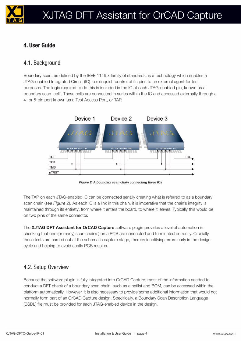
Boundary scan, as defined by the IEEE 1149.x family of standards, is a technology which enables aJTAG-enabled Integrated Circuit (IC) to relinquish control of its pins to an external agent for testpurposes. The logic required to do this is included in the IC at each JTAG-enabled pin, known as aboundary scan ‘cell’. These cells are connected in series within the IC and accessed externally through a4- or 5-pin port known as a Test Access Port, or TAP.
The TAP on each JTAG-enabled IC can be connected serially creating what is referred to as a boundaryscan chain (see Figure 2). As each IC is a link in this chain, it is imperative that the chain’s integrity ismaintained through its entirety; from where it enters the board, to where it leaves. Typically this would beon two pins of the same connector.
The XJTAG DFT Assistant for OrCAD Capture software plugin provides a level of automation inchecking that one (or many) scan chain(s) on a PCB are connected and terminated correctly. Crucially,these tests are carried out at the schematic capture stage, thereby identifying errors early in the designcycle and helping to avoid costly PCB respins.
4.2. Setup Overview
Because the software plugin is fully integrated into OrCAD Capture, most of the information needed toconduct a DFT check of a boundary scan chain, such as a netlist and BOM, can be accessed within theplatform automatically. However, it is also necessary to provide some additional information that would notnormally form part of an OrCAD Capture design. Specifically, a Boundary Scan Description Language(BSDL) file must be provided for each JTAG-enabled device in the design.
XJTAG-DFTO-Guide-IP-01 www.xjtag.com
Figure 2: A boundary scan chain connecting three ICs

Installation & User Guide | page 5XJTAG-DFTO-Guide-IP-01 www.xjtag.com
In order to comply with the IEEE standard, it is a requirement for the IC manufacturer to supply a BSDL filefor each JTAG-enabled device. Sourcing BSDL files is, therefore, not difficult but it is recommended theybe obtained direct from the manufacturer’s website in order to guarantee they are the latest versions.
BSDL files can be assigned to ICs using the XJTAG DFT Assistant for OrCAD Capture interface, whichis in a separate window but will always stay visible above the OrCAD Capture main window (see Figure 3).
Once a BSDL file is imported and associated with an IC it is stored as part of the OrCAD Capture design,so the process does not need to be repeated.
Other non-JTAG devices that may propagate boundary scan access or form a part of the JTAG chaininclude standard logic and passive devices. The XJTAG DFT Assistant for OrCAD Capture will helpidentify any such devices in the schematic and allow the designer to categorise them. In addition, pressingthe Suggest Categorisations button will attempt to auto-categorise any commonly seen componentssuch as series resistors and pull resistors. Any devices not categorised can be assigned later if the designis exported and opened in XJDeveloper (see Section 5.0 for more details). All categorisation informationwill also be stored as part of the design.
XJTAG DFT Assistant for OrCAD Capture
Figure 3: The DFT Assistant User Interface
Installation & User Guide | page 6
XJTAG DFT Assistant for OrCAD Capture
4.3. Workflow
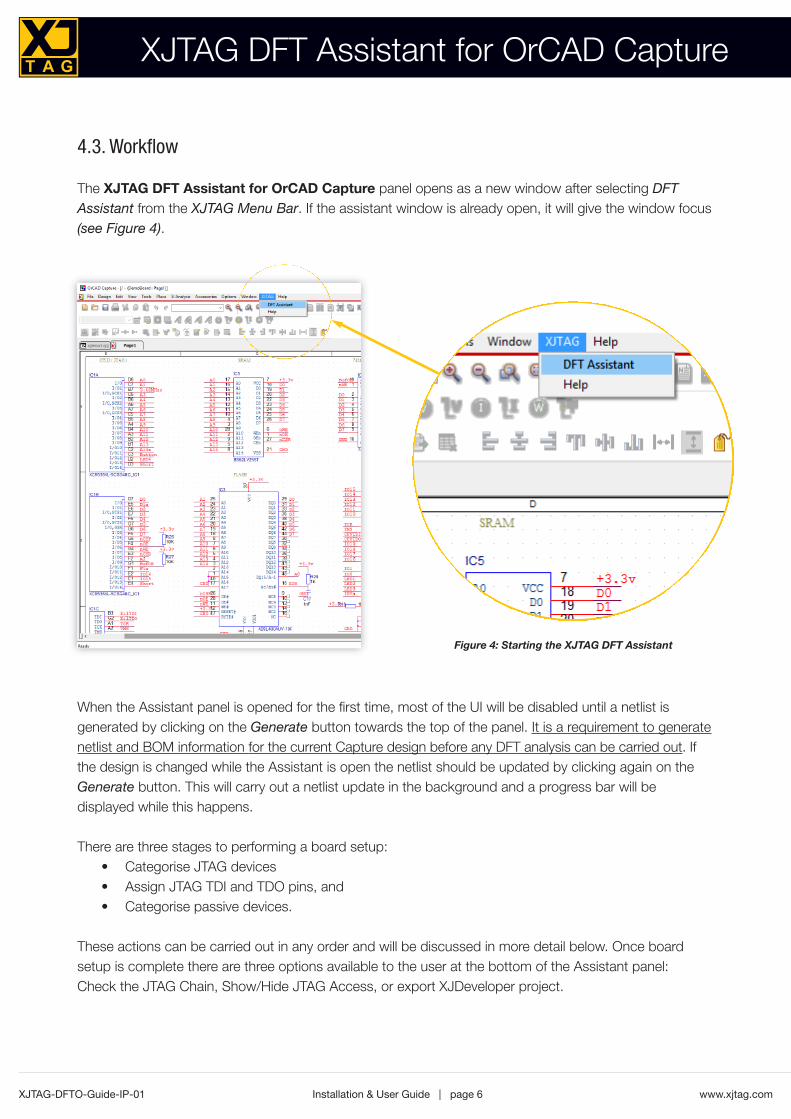
The XJTAG DFT Assistant for OrCAD Capture panel opens as a new window after selecting DFTAssistant from the XJTAG Menu Bar. If the assistant window is already open, it will give the window focus(see Figure 4).
When the Assistant panel is opened for the first time, most of the UI will be disabled until a netlist isgenerated by clicking on the Generate button towards the top of the panel. It is a requirement to generatenetlist and BOM information for the current Capture design before any DFT analysis can be carried out. Ifthe design is changed while the Assistant is open the netlist should be updated by clicking again on theGenerate button. This will carry out a netlist update in the background and a progress bar will bedisplayed while this happens.
There are three stages to performing a board setup: Categorise JTAG devices •Assign JTAG TDI and TDO pins, and •Categorise passive devices. •
These actions can be carried out in any order and will be discussed in more detail below. Once boardsetup is complete there are three options available to the user at the bottom of the Assistant panel: Check the JTAG Chain, Show/Hide JTAG Access, or export XJDeveloper project.
XJTAG-DFTO-Guide-IP-01 www.xjtag.com
Figure 4: Starting the XJTAG DFT Assistant

Installation & User Guide | page 7XJTAG-DFTO-Guide-IP-01 www.xjtag.com
4.3.1. Categorising JTAG devices
JTAG-enabled devices in the schematic should be identified by the user and assigned a BSDL file. It isrecommended to obtain BSDL files from the appropriate part manufacturer’s website. To associate aBSDL file with its component, press the Add button next to the JTAG devices list view (see Figure 5). TheAdd JTAG Device dialog box will open containing a device selector control and BSDL file selector control.Start typing a device reference into the device box and it will provide suggestions for devices in the circuit.
The path to the BSDL file will be stored as a parameter of the device in the Capture design. Any plaintext file format is acceptable for use as a BSDL file and the plugin will automatically check that the fileparses correctly. However the onus is on the user to ensure that the BSDL file is the correct one for thedevice chosen. An incorrect BSDL file may lead to incorrect and misleading results when using theXJTAG Chain Checker or XJTAG Access Viewer.
4.3.2. Defining JTAG Chain(s)
As outlined above, a TAP (Test Access Port) comprises a minimum of four signals: TDI (Test Data In);TDO (Test Data Out); TCLK (Test Clock), and TMS (Test Mode Select). An optional fifth signal, nTRST(Test Reset) may also be present, which disables boundary scan when held low.
It is essential that the JTAG chain (TAP) is routed to the correct pins on each JTAG-enabled device inthe chain. For the chain to function correctly it must be possible to trace a route from the board TDI pin(where the chain enters the board), into TDI and out of TDO of each JTAG device in turn and then to theboard TDO pin (where the chain leaves the board). It is possible to implement more than one chain on asingle design, however each JTAG-enabled device may only be connected to a single JTAG chain. TheXJTAG DFT Assistant for OrCAD Capture software plugin provides a fully integrated way of ensuringscan chains are connected as intended and correctly.
In order to achieve this it is necessary to identify the TDI and TDO pins on each chain to determine howthe PCB will be connected to the JTAG testing hardware. It is possible to define up to 4 scan chains ina single design. To select the TDI and TDO pins for each chain, click on the Add button next to the TDIand TDO list view, and this will open the Add Chain dialog box (see Figure 6).
XJTAG DFT Assistant for OrCAD Capture
Figure 5 Associating a BSDL file to an IC in the schematic
Installation & User Guide | page 8
XJTAG DFT Assistant for OrCAD Capture
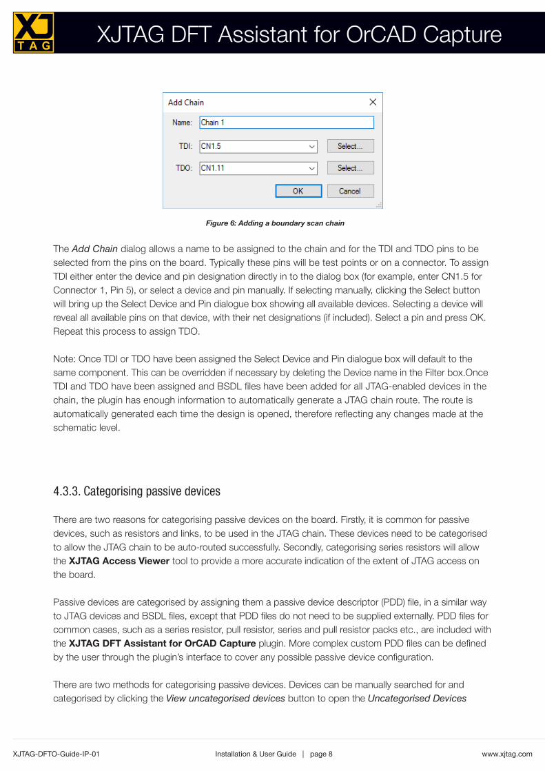
The Add Chain dialog allows a name to be assigned to the chain and for the TDI and TDO pins to beselected from the pins on the board. Typically these pins will be test points or on a connector. To assignTDI either enter the device and pin designation directly in to the dialog box (for example, enter CN1.5 forConnector 1, Pin 5), or select a device and pin manually. If selecting manually, clicking the Select buttonwill bring up the Select Device and Pin dialogue box showing all available devices. Selecting a device willreveal all available pins on that device, with their net designations (if included). Select a pin and press OK.Repeat this process to assign TDO.
Note: Once TDI or TDO have been assigned the Select Device and Pin dialogue box will default to thesame component. This can be overridden if necessary by deleting the Device name in the Filter box.OnceTDI and TDO have been assigned and BSDL files have been added for all JTAG-enabled devices in thechain, the plugin has enough information to automatically generate a JTAG chain route. The route isautomatically generated each time the design is opened, therefore reflecting any changes made at theschematic level.
4.3.3. Categorising passive devices
There are two reasons for categorising passive devices on the board. Firstly, it is common for passivedevices, such as resistors and links, to be used in the JTAG chain. These devices need to be categorisedto allow the JTAG chain to be auto-routed successfully. Secondly, categorising series resistors will allowthe XJTAG Access Viewer tool to provide a more accurate indication of the extent of JTAG access onthe board.
Passive devices are categorised by assigning them a passive device descriptor (PDD) file, in a similar wayto JTAG devices and BSDL files, except that PDD files do not need to be supplied externally. PDD files forcommon cases, such as a series resistor, pull resistor, series and pull resistor packs etc., are included withthe XJTAG DFT Assistant for OrCAD Capture plugin. More complex custom PDD files can be definedby the user through the plugin’s interface to cover any possible passive device configuration.
There are two methods for categorising passive devices. Devices can be manually searched for andcategorised by clicking the View uncategorised devices button to open the Uncategorised Devices
XJTAG-DFTO-Guide-IP-01 www.xjtag.com
Figure 6: Adding a boundary scan chain

Installation & User Guide | page 9XJTAG-DFTO-Guide-IP-01 www.xjtag.com
dialog (see Figure 7). Alternatively the XJTAG DFT Assistant for OrCAD Capture can suggestcategorisations automatically by clicking the Suggest Categorisations button. The Suggest Categorisationdialog will provide PDD files for any passive devices that can be auto-categorised (see Figure 8).
XJTAG DFT Assistant for OrCAD Capture
Figure 7: The Uncategorised Devices dialog box
Figure 8: The Suggest Categorisation dialog box

Installation & User Guide | page 10
XJTAG DFT Assistant for OrCAD Capture
XJTAG-DFTO-Guide-IP-01 www.xjtag.com
To avoid categorising passive devices that will not affect the extent of JTAG access, the SuggestCategorisation dialog is limited to those devices already on nets with JTAG access.
To uncategorise an already categorised device, press the View categorised devices button which willbring up a list of all passive devices categorised so far. From here a device, or group of devices, can beselected and uncategorised.
4.3.4. Manually creating a passive device
To manually create a passive device (using a new PDD file) open the Uncategorised Devices dialog andselect a device, either by navigating the tree view or typing the device reference into the filter box. Clickingthe Only Show Accessible Devices checkbox will toggle between showing all devices in the circuit or onlyshowing devices on nets with JTAG access. Once a device, or group of devices, is selected press theCategorise As Passive button to open the Assign Device dialog (see Figure 9).
The top half of the dialog will provide suggestions for possible PDD files that match the parameters of thedevice. Selecting one of these and pressing OK will categorise the device. If no suitable PDD file is presentin the top list there are the options to browse for an existing PDD file that was created previously or tocreate a new one. Pressing the Create File button will open the New PDD File Dialog (see Figure 10).
Figure 9: Assigning a device as a passive

Installation & User Guide | page 11XJTAG-DFTO-Guide-IP-01 www.xjtag.com
To create a new PDD file, enter a filename and (optionally) some description text and then addconnections between pins. Connections can be of two types, either a simple connection (where the twopins are electrically linked or there is a low resistance value between them) or a pull connection (for pullresistors). Once a type is selected, and the pin numbers have been entered, press Add to add theconnection to the list. Once all connections are added, click OK to create the new file.
Connections which do not fall into these types (e.g. terminations) should be left uncategorised – if theproject is exported into XJDeveloper they can be set up there.
4.4. Check JTAG Chain
Once setup is complete, clicking on the Check Chain button will initialise the XJTAG Chain Checker.This will open the Chain Check Results dialog box (see Figure 11), giving a breakdown of any potentialerrors or causes for concern in the JTAG chains that have been defined.
The errors and warnings reported by the XJTAG Chain Checker are split into 3 categories; TAP netconnection errors, TAP net termination errors and compliance pin errors. Connection errors areproblems that prevent a JTAG chain being routed successfully and are classed as fatal errors as theywill prevent any JTAG access through that chain. Termination errors are caused by TAP nets not beingterminated to power or ground properly, potentially causing signal integrity issues. The errors andwarnings will make recommendations for how best to prevent this. Compliance pins are pins on JTAGdevices that must be set correctly to enable the device’s boundary scan operation. The pins and valuesrequired are set out in the Compliance Patterns section of the BSDL file and the compliance pin errorswill report any errors in the circuit design that prevent these pins being set correctly.
XJTAG DFT Assistant for OrCAD Capture
Figure 10: Creating a new PDD file
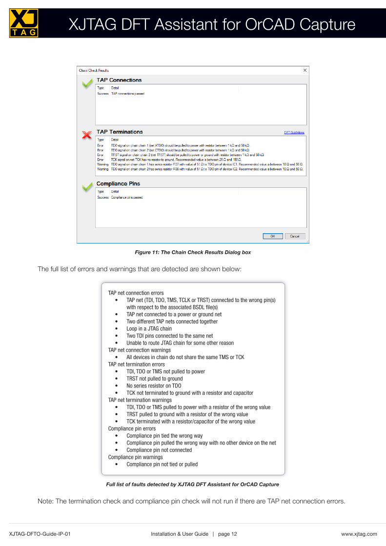
The full list of errors and warnings that are detected are shown below:
Note: The termination check and compliance pin check will not run if there are TAP net connection errors.
Installation & User Guide | page 12
XJTAG DFT Assistant for OrCAD Capture
XJTAG-DFTO-Guide-IP-01 www.xjtag.com
Figure 11: The Chain Check Results Dialog box
TAP net connection errorsTAP net (TDI, TDO, TMS, TCLK or TRST) connected to the wrong pin(s)•with respect to the associated BSDL file(s)TAP net connected to a power or ground net•Two different TAP nets connected together•Loop in a JTAG chain•Two TDI pins connected to the same net•Unable to route JTAG chain for some other reason•
TAP net connection warningsAll devices in chain do not share the same TMS or TCK•
TAP net termination errors TDI, TDO or TMS not pulled to power•TRST not pulled to ground•No series resistor on TDO•TCK not terminated to ground with a resistor and capacitor•
TAP net termination warningsTDI, TDO or TMS pulled to power with a resistor of the wrong value•TRST pulled to ground with a resistor of the wrong value•TCK terminated with a resistor/capacitor of the wrong value•
Compliance pin errorsCompliance pin tied the wrong way•Compliance pin pulled the wrong way with no other device on the net•Compliance pin not connected•
Compliance pin warningsCompliance pin not tied or pulled•
Full list of faults detected by XJTAG DFT Assistant for OrCAD Capture

Installation & User Guide | page 13XJTAG-DFTO-Guide-IP-01 www.xjtag.com
XJTAG DFT Assistant for OrCAD Capture
4.5. XJTAG Access Viewer
At any stage of the board setup, clicking on the Show JTAG Access button will highlight the JTAGaccess on each page of the schematic diagram. This feature shows the best level of access available oneach net, as long as all JTAG devices categorised so far are connected up correctly. The nets will becolour-coded, as shown in Figure 12. The nets accessible to boundary scan testing will be highlightedusing these colour codes, as shown in Figure 13.
Figure 12: Colour-coded nets showing boundary scan access
Figure 13: Screenshot showing colour-coded boundary scan access

Installation & User Guide | page 14
XJTAG DFT Assistant for OrCAD Capture
XJTAG-DFTO-Guide-IP-01 www.xjtag.com
Figure 14: Boundary scan access to Power/Ground nets only
Figure 15: Nets with no boundary scan access
Ticking and unticking on access types in the JTAG Access Legend toggles the thickness of those nets inthe design (see Figures 14-15).
Pressing the Hide JTAG Access button, closing the JTAG Access Legend or XJTAG DFT Assistant window,closing the design or closing OrCAD Capture will return all nets to their original colours and thickness.

Installation & User Guide | page 15XJTAG-DFTO-Guide-IP-01 www.xjtag.com
XJTAG DFT Assistant for OrCAD Capture
5. Export XJDeveloper Project
At any stage, users with a licence from XJTAG can export the information they have entered as anXJDeveloper project. By clicking on Export XJDeveloper Project, the XJTAG DFT Assistant forOrCAD Capture will look for a valid XJDeveloper licence. If no licence is detected, the following box willappear (see Figure 16):
If no valid XJDeveloper licence is available, click on Get Started Now to open a webpage detailing thefree evaluation offer on XJTAG’s website.
Please note, the exported project requires V3.4 or higher of XJDeveloper
5.1. Boundary Scan test development
XJDeveloper is XJTAG’s Integrated Development Environment (IDE) for the development and execution ofinterconnection and functional tests run over Boundary Scan. It provides all the functionality needed to executeboundary scan tests on a prototype board, as well as production tests in a manufacturing environment.
XJDeveloper includes an extensive library of functional tests for non JTAG-enabled devices. It alsoincludes a powerful test development language called XJEase, which makes it easy to develop furthertests and apply them through an XJLink2 Controller.
Figure 16: Missing XJDeveloper licence dialog box

Installation & User Guide | page 16
XJTAG DFT Assistant for OrCAD Capture
XJTAG-DFTO-Guide-IP-01 www.xjtag.com
5.2. Migrating a project to XJDeveloper
The setup process completed within the XJTAG DFT Assistant for OrCAD Capture can be exported asan XJDeveloper project, and simply opened from within XJDeveloper. The user can then continue withthe board setup process, by categorising the remaining non JTAG-enabled devices which have not beencategorised in the XJTAG DFT Assistant. A full interconnectivity test can then be carried out on the PCBonce manufactured, to identify a wide range of manufacturing faults. The full list of faults that can bedetected using XJTAG’s boundary scan technology is illustrated in Figure 17.
6. Further reading
For more information on XJTAG’s boundary scan technology, visit www.xjtag.com. For an extensive guide to Design For Test best-practices for boundary scan testing, visit:www.xjtag.com/about-jtag/design-for-test-guidelines
+ 3.3v
+ 3.3v
Missing pull resistorStuck at 1OKShortShortResistive shortResistive shortOpen
Logic connection
Stuck at 0Missing pull resistor
Figure 17: The full range of faults detectable using XJTAG’s boundary scan technology

Installation & User Guide | page 17XJTAG-DFTO-Guide-IP-01 www.xjtag.com
About XJTAG
XJTAG is a world leading supplier of JTAG boundary-scan hardware and software tools. The companyfocuses on innovative product development and high quality technical support.
XJTAG products use IEEE Std.1149.x (JTAG boundary-scan) to enable engineers to debug, test andprogram electronic circuits quickly and easily. This can significantly shorten the electronic design,development and manufacturing processes.
XJTAG, based in Cambridge, UK, released version 1.0 of its boundary-scan tools in 2003 and startingfrom the UK, XJTAG has expanded and is now a business with multi-million dollar worldwide sales. XJTAGwas the first boundary-scan solution to offer a common platform for use by design and developmentengineers, test engineers, contract manufacturers and field test engineers, providing testing of not onlyJTAG-enabled devices but non-JTAG devices as well. This change of emphasis towards test re-use andusability has driven the boundary-scan market forward, as board designers realised that they can have thetest equipment on their benches and then re-use tests at production time.
XJTAG believes in being open – clients can see and edit the script files that are used to test for non-JTAGdevices. If a revised device comes along, or the client has a problem, they can alter or debug the testthemselves if they do not wish to (or are unable to) involve XJTAG.
Clients across a wide range of industries benefit from using XJTAG products. These include aerospace,automotive, defence, medical, manufacturing, networking and telecommunications. The company sellsand supports its products worldwide and works closely with over 50 experienced and professionaldistributors and technology partners across the globe. XJTAG is part of Cambridge Technology Group.
UK HeadquartersXJTAGSt John's Innovation CentreCowley RoadCambridgeCB4 0DSUnited Kingdom
Tel: +44 (0)1223 223007Fax: +44 (0)1223 223009
Email: [email protected] Web site: www.xjtag.com
XJTAG DFT Assistant for OrCAD Capture