MANUALOWNER’S
OB No.003-11113-2AF1
MFS 6BZMFS 8B
MFS 9.8BOriginal instructions

ENOM00001-0
READ THIS MANUAL BEFORE USING THE OUTBOARD MOTOR. FAILURE TO FOLLOW THEINSTRUCTIONS AND SAFETY PRECAUTIONS IN THIS MANUAL CAN RESULT IN SERIOUSINJURY OR DEATH. KEEP THIS MANUAL IN A SAFE LOCATION FOR FUTURE REFERENCE.
Copyright © 2016 Tohatsu Corporation. All rights reserved. No part of this manual may be reproduced or
transmitted in any from or by any means without the express written permission of Tohatsu Corporation.
3
YOUR TOHATSU OUTBOARD MOTOR
ENOM00006-A
To You, Our CustomerThank you for selecting a TOHATSU outboard motor. You are now the proud owner of an
excellent outboard motor that will service you for many years to come.
This manual should be read in its entirety and the inspection and maintenance procedures
described later in this manual should be followed carefully. Should a problem arise with the
outboard motor, please follow the troubleshooting procedures listed at the end of this
manual. If the problem persists, contact an authorized TOHATSU service shop or dealer.
Please always keep this manual together with the outboard motor as a reference to every-
one who uses the outboard motor. If the outboard motor is resold, make sure the manual
is passed on to the next owner.
We hope you will enjoy your outboard motor and wish you good luck in your boating
adventures.
TOHATSU CORPORATION
ENOM00113-0
EC DECLARATION OF CONFORMITY (DoC)This product conforms to certain portion of the European Parliament directive. DoC con-
tains the following information;
Name and Address of the manufacturer.
Applied community directives
Reference standard
Description of the product. (Model name and serial number)
Signature of the responsible person (Name / Title / Date and place of issue).
ENOM00002-0
OWNER REGISTRATION AND IDENTIFICATIONUpon purchasing this product, be sure that the WARRANTY CARD is correctly and com-
pletely filled out and mailed to the addressee noted there on. This WARRANTY CARD
identifies you as the legal owner of the product and serves as your warranty registration.
TO THE EXTENT PERMITTED BY APPLICABLE LAW, YOUR OUTBOARD MOTOR WILL
NOT BE COVERED BY THE APPLICABLE LIMITED WARRANTY, IF THIS PROCEDURE IS
NOT FOLLOWED.
ENOM00003-0
PRE-DELIVERY CHECKBe sure that the product has been checked by an authorized TOHATSU dealer before you
take delivery.
4
ENOM00005-A
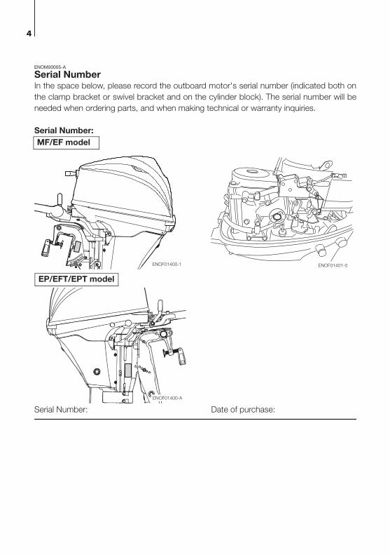
Serial NumberIn the space below, please record the outboard motor's serial number (indicated both on
the clamp bracket or swivel bracket and on the cylinder block). The serial number will be
needed when ordering parts, and when making technical or warranty inquiries.
Serial Number:
Serial Number: Date of purchase:
ENOF01401-0
ENOF01400-A
ENOF01400-1
MF/EF model
EP/EFT/EPT model
5
ENOM00007-0
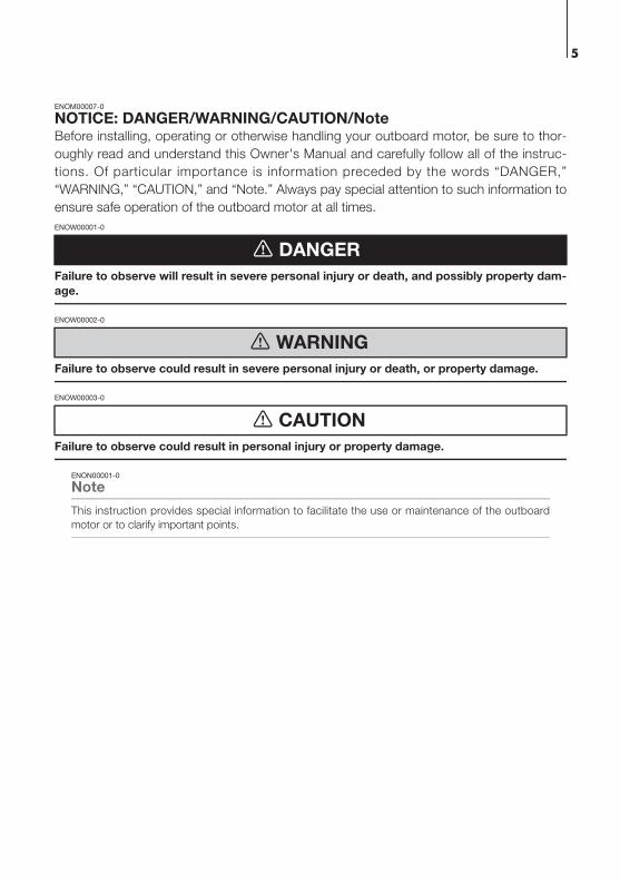
NOTICE: DANGER/WARNING/CAUTION/NoteBefore installing, operating or otherwise handling your outboard motor, be sure to thor-
oughly read and understand this Owner's Manual and carefully follow all of the instruc-
tions. Of particular importance is information preceded by the words “DANGER,”
“WARNING,” “CAUTION,” and “Note.” Always pay special attention to such information to
ensure safe operation of the outboard motor at all times.
ENOW00001-0
Failure to observe will result in severe personal injury or death, and possibly property dam-
age.
ENOW00002-0
Failure to observe could result in severe personal injury or death, or property damage.
ENOW00003-0
Failure to observe could result in personal injury or property damage.
ENON00001-0
Note
This instruction provides special information to facilitate the use or maintenance of the outboard
motor or to clarify important points.
DANGER
WARNING
CAUTION

1. GENERAL SAFETY INFORMATION. . . . . . . . . . . . . . . . . . . . . . . . . . . . . . . 10
2. SPECIFICATIONS . . . . . . . . . . . . . . . . . . . . . . . . . . . . . . . . . . . . . . . . . . . . . 12
3. PARTS NAME . . . . . . . . . . . . . . . . . . . . . . . . . . . . . . . . . . . . . . . . . . . . . . . . 16
4. LABEL LOCATIONS . . . . . . . . . . . . . . . . . . . . . . . . . . . . . . . . . . . . . . . . . . . 19
5. INSTALLATION . . . . . . . . . . . . . . . . . . . . . . . . . . . . . . . . . . . . . . . . . . . . . . . 23
1. Mounting the outboard motor on boat . . . . . . . . . . . . . . . . . . . . . . . . . . . 23
2. Remote control device installation. . . . . . . . . . . . . . . . . . . . . . . . . . . . . . . 25
3. Battery installation . . . . . . . . . . . . . . . . . . . . . . . . . . . . . . . . . . . . . . . . . . . 26
6. PRE-OPERATING PREPARATIONS . . . . . . . . . . . . . . . . . . . . . . . . . . . . . . 28
1. Fuel handling . . . . . . . . . . . . . . . . . . . . . . . . . . . . . . . . . . . . . . . . . . . . . . . 28
2. Fuel filling . . . . . . . . . . . . . . . . . . . . . . . . . . . . . . . . . . . . . . . . . . . . . . . . . 29
3. Engine oil recommendation . . . . . . . . . . . . . . . . . . . . . . . . . . . . . . . . . . . . 30
4. Break-In . . . . . . . . . . . . . . . . . . . . . . . . . . . . . . . . . . . . . . . . . . . . . . . . . . . 31
5. Warning system . . . . . . . . . . . . . . . . . . . . . . . . . . . . . . . . . . . . . . . . . . . . . 32
7. ENGINE OPERATION . . . . . . . . . . . . . . . . . . . . . . . . . . . . . . . . . . . . . . . . . . 35
Before starting . . . . . . . . . . . . . . . . . . . . . . . . . . . . . . . . . . . . . . . . . . . . . . . . 35
1. Fuel feeding . . . . . . . . . . . . . . . . . . . . . . . . . . . . . . . . . . . . . . . . . . . . . . . . 35
2. Starting the engine . . . . . . . . . . . . . . . . . . . . . . . . . . . . . . . . . . . . . . . . . . 36
3. Warming up the engine . . . . . . . . . . . . . . . . . . . . . . . . . . . . . . . . . . . . . . . 41
4. Forward, reverse, and acceleration . . . . . . . . . . . . . . . . . . . . . . . . . . . . . . 42
5. Stopping the engine . . . . . . . . . . . . . . . . . . . . . . . . . . . . . . . . . . . . . . . . . 44
6. Steering . . . . . . . . . . . . . . . . . . . . . . . . . . . . . . . . . . . . . . . . . . . . . . . . . . . 46
7. Trim angle . . . . . . . . . . . . . . . . . . . . . . . . . . . . . . . . . . . . . . . . . . . . . . . . . 47
8. Tilt up and down . . . . . . . . . . . . . . . . . . . . . . . . . . . . . . . . . . . . . . . . . . . . 49
9. Shallow water operation . . . . . . . . . . . . . . . . . . . . . . . . . . . . . . . . . . . . . . 52
8. REMOVING AND CARRYING THE OUTBOARD MOTOR. . . . . . . . . . . . . . 55
1. Removing the outboard motor. . . . . . . . . . . . . . . . . . . . . . . . . . . . . . . . . . 55
2. Carrying the outboard motor . . . . . . . . . . . . . . . . . . . . . . . . . . . . . . . . . . . 55
3. Traillering . . . . . . . . . . . . . . . . . . . . . . . . . . . . . . . . . . . . . . . . . . . . . . . . . . 56
9. ADJUSTMENT . . . . . . . . . . . . . . . . . . . . . . . . . . . . . . . . . . . . . . . . . . . . . . . . 58
1. Steering friction . . . . . . . . . . . . . . . . . . . . . . . . . . . . . . . . . . . . . . . . . . . . . 58
2. Throttle grip friction . . . . . . . . . . . . . . . . . . . . . . . . . . . . . . . . . . . . . . . . . . 58
3. Remote control lever friction . . . . . . . . . . . . . . . . . . . . . . . . . . . . . . . . . . . 58
4. Trim tab adjustment . . . . . . . . . . . . . . . . . . . . . . . . . . . . . . . . . . . . . . . . . 59
10. INSPECTION AND MAINTENANCE . . . . . . . . . . . . . . . . . . . . . . . . . . . . . . . 60
1. Daily Inspection . . . . . . . . . . . . . . . . . . . . . . . . . . . . . . . . . . . . . . . . . . . . . 61
2. Periodic Inspection . . . . . . . . . . . . . . . . . . . . . . . . . . . . . . . . . . . . . . . . . . 66
3. Off-season storage . . . . . . . . . . . . . . . . . . . . . . . . . . . . . . . . . . . . . . . . . . 77
4. Pre-season check . . . . . . . . . . . . . . . . . . . . . . . . . . . . . . . . . . . . . . . . . . . 80
5. Submerged outboard motor . . . . . . . . . . . . . . . . . . . . . . . . . . . . . . . . . . . 80
6. Cold weather precautions . . . . . . . . . . . . . . . . . . . . . . . . . . . . . . . . . . . . . 81
7. Striking underwater object . . . . . . . . . . . . . . . . . . . . . . . . . . . . . . . . . . . . . 81
8. Auxiliary outboard motor operation . . . . . . . . . . . . . . . . . . . . . . . . . . . . . . 81
CONTENTS

11. TROUBLESHOOTING . . . . . . . . . . . . . . . . . . . . . . . . . . . . . . . . . . . . . . . . . . 82
12. ACCESSORIES KIT . . . . . . . . . . . . . . . . . . . . . . . . . . . . . . . . . . . . . . . . . . . . 84
13. PROPELLER TABLE . . . . . . . . . . . . . . . . . . . . . . . . . . . . . . . . . . . . . . . . . . . 85

9
1 GENERAL SAFETY INFORMATION
2. SPECIFICATIONS
3. PARTS NAME
4. LABEL LOCATIONS
5. INSTALLATION
6. PRE-OPERATING PREPARATIONS
7. ENGINE OPERATION
8. REMOVING AND CARRYING THE OUTBOARD MOTOR
9. ADJUSTMENT
10. INSPECTION AND MAINTENANCE
11.TROUBLESHOOTING
12.ACCESSORIES KIT
13.PROPELLER TABLE
INDEX
2
14
3
4
5
6
7
8
9
10
11
12
13
14
1
10
1
GENERAL SAFETY INFORMATION
ENOM00009-0
SAFE OPERATION OF BOATAs the operator/driver of the boat, you are responsible for the safety of those aboard and
those in other boat around yours, and for following local boating regulations. You should
be thoroughly knowledgeable on how to correctly operate the boat, outboard motor, and
accessories. To learn about the correct operation and maintenance of the outboard motor,
please read through this manual carefully.
It is very difficult for a person standing or floating in the water to take evasive action should
he or she see a power boat heading in his/her direction, even at a slow speed. Therefore,
when your boat is in the immediate vicinity of people in the water, the outboard motor
should be shifted to neutral and shut off.
ENOW00005-0
SERIOUS INJURY IS LIKELY IF A PERSON IN THE WATER MAKES CONTACT WITH A MOV-
ING BOAT, GEAR HOUSING, PROPELLER, OR ANY SOLID DEVICE RIGIDLY ATTACHED TO
A BOAT OR GEAR HOUSING.
ENOM0008-A
EMERGENCY STOP SWITCHThe Emergency Stop Switch will stall the outboard motor when the stop switch lanyard is
pulled off. This stop switch lanyard has to be attached to the operator of the outboard
motor to minimize or prevent injuries from the propeller in case the operator falls over-
board.
It is operator’s responsibility to use the Emergency Stop Switch Lanyard.
ENOW00004-A
Accidental activation of the Emergency Stop Switch (such as the tether being pulled out in
heavy seas) could cause passengers to lose their balance and even fall overboard, or it
could result in loss of power in heavy seas, strong currents, or high winds. Loss of control
while mooring is another potential hazard.
To minimize accidental activation of the Emergency Stop Switch, the 500 mm (20 in.) stop
switch lanyard is coiled and can extended to a full 1300 mm (51 in.).
ENOM00800-A
PERSONAL FLOATATION DEVICEAs the operator/driver and passenger of the boat, you are responsible to wear a PFD (Per-
sonal Floatation Device) while on the boat.
WARNING
WARNING

GENERAL SAFETY INFORMATION 11
1ENOM00010-0
SERVICING, REPLACEMENT PARTS & LUBRICANTSWe recommend that only an authorized service shop perform service or maintenance on
this outboard motor. Be sure to use genuine parts, genuine lubricants, or recommended
lubricants.
ENOM00011-A
MAINTENANCEAs the owner of this outboard motor, you should be acquainted with correct maintenance
procedures following maintenance section of this manual (See page 60). It is the opera-
tor's responsibility to perform all safety checks and to ensure that all lubrication and main-
tenance instructions are complied with for safe operation. Please comply with all
instructions concerning lubrication and maintenance. You should take the engine to an
authorized dealer or service shop for periodic inspection at the prescribed intervals.
Correct periodic maintenance and proper care of this outboard motor will reduce the
chance of problems and limit overall operating expenses.
Carbon Monoxide Poisoning Hazard
Exhaust gas contains carbon monoxide, a colorless and odorless gas which can be fatal if
inhaled for any length of time.
Never start or operate the engine indoors or in any space which is not well ventilated.
Gasoline
Gasoline and its vapors are very flammable and can be explosive. Use extreme care when
handling gasoline. You should be thoroughly knowledgeable on how to correctly handle
gasoline by reading this manual.
12
2
SPECIFICATIONS
ENOM00810-A
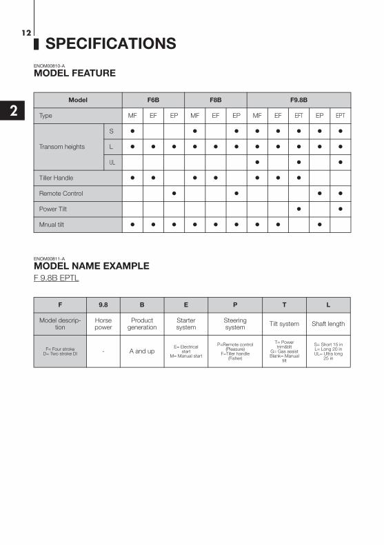
MODEL FEATURE
*1: Option
ENOM00811-A
MODEL NAME EXAMPLE
F 9.8B EPTL
Model F6B F8B F9.8B
Type MF EF EP MF EF EP MF EF EFT EP EPT
Transom heights
S
L
UL
Tiller Handle
Remote Control
Power Tilt
Mnual tilt
F 9.8 B E P T L
Model descrip-tion
Horse power
Product generation
Starter system
Steeringsystem
Tilt system Shaft length
F= Four strokeD= Two stroke DI - A and up
E= Electrical start
M= Manual start
P=Remote control (Pleasure)
F=Tiller handle (Fisher)
T= Power trim&tilt
G= Gas assistBlank= Manual
tilt
S= Short 15 inL= Long 20 inUL= Ultra long
25 in
SPECIFICATIONS 13
2
ENOM00501-0
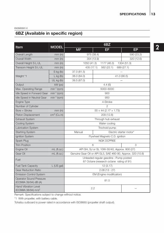
Remark: Specifications subject to change without notice.
*1 With propeller, with battery cable.
Tohatsu outboard is power rated in accordance with ISO8665 (propeller shaft output).
6BZ (Available in specific region)
Item MODEL6BZ
MF EF EP
Overall Length mm (in) 975 (38.4) 590 (23.2)
Overall Width mm (in) 354 (13.9) 320 (12.6)
Overall Height S·L·UL mm (in) 1050 (41.3) 1177 (46.3) 1304 (51.3)
Transom Height S·L·UL mm (in) 435 (17.1) 562 (22.1) 689 (27.1)
Weight *1
S kg (lb) 37.0 (81.5) —
L kg (lb) 38.0 (84.0) 41.0 (90.5)
UL kg (lb) 39.5 (87.0) —
Output kW (ps) 4.4 (6)
Max. Operating Range min-1 (rpm) 5000–6000
Idle Speed in Forward Gear min-1 (rpm) 900
Idle Speed in Neutral Gear min-1 (rpm) 950
Engine Type 4-Stroke
Number of Cylinder 2
Bore × Stroke mm (in) 55 × 44 (2.17 × 1.73)
Piston Displacement cm3 (Cu in) 209 (12.8)
Exhaust System Through hub exhaust
Cooling System Water cooling
Lubrication System Trochoid pump
Startring System Manual Electric starter motor*
Ignition System Flywheel Magneto C.D. ignition
Spark Plug NGK DCPR6E
Trim Position 6 3
Engine Oil mL (fl.oz.) API SH, SJ or SL 10W-30/40, Approx. 800 (27)
Gear Oil mL (fl.oz.) Genuine Gear Oil or API GL5, SAE #80-90, Approx. 320 (10.8)
FuelUnleaded regular gasoline : Pump posted
87 Octane (research octane rating of 91)
Fuel Tank Capacity L (US gal) 12 (3.17)
Gear Reduction Ratio 2.08 (13 : 27)
Emission Control System EM (Engine modification)
Operator Sound Pressure
(ICOMIA 39/94) dB (A)81.5
Hand Vibration Level
(ICOMIA 38/94) m/s2 2.2 —
SPECIFICATIONS14
2
ENOM00502-0
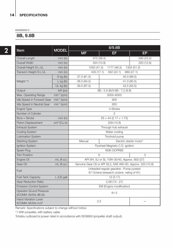
Remark: Specifications subject to change without notice.
*1 With propeller, with battery cable.
Tohatsu outboard is power rated in accordance with ISO8665 (propeller shaft output).
8B, 9.8B
Item MODEL8/9.8B
MF EF EP
Overall Length mm (in) 975 (38.4) 590 (23.2)
Overall Width mm (in) 354 (13.9) 320 (12.6)
Overall Height S·L·UL mm (in) 1050 (41.3) 1177 (46.3) 1304 (51.3)
Transom Height S·L·UL mm (in) 435 (17.1) 562 (22.1) 689 (27.1)
Weight *1
S kg (lb) 37.0 (81.5) 40.0 (88.0)
L kg (lb) 38.0 (84.0) 41.0 (90.5)
UL kg (lb) 39.5 (87.0) 42.5 (93.5)
Output kW (ps) 8B : 5.9 (8)/9.8B : 7.2 (9.8)
Max. Operating Range min-1 (rpm) 5000–6000
Idle Speed in Forward Gear min-1 (rpm) 900
Idle Speed in Neutral Gear min-1 (rpm) 950
Engine Type 4-Stroke
Number of Cylinder 2
Bore × Stroke mm (in) 55 × 44 (2.17 × 1.73)
Piston Displacement cm3 (Cu in) 209 (12.8)
Exhaust System Through hub exhaust
Cooling System Water cooling
Lubrication System Trochoid pump
Startring System Manual Electric starter motor*
Ignition System Flywheel Magneto C.D. ignition
Spark Plug NGK DCPR6E
Trim Position 6 3
Engine Oil mL (fl.oz.) API SH, SJ or SL 10W-30/40, Approx. 800 (27)
Gear Oil mL (fl.oz.) Genuine Gear Oil or API GL5, SAE #80-90, Approx. 320 (10.8)
FuelUnleaded regular gasoline : Pump posted
87 Octane (research octane rating of 91)
Fuel Tank Capacity L (US gal) 12 (3.17)
Gear Reduction Ratio 2.08 (13 : 27)
Emission Control System EM (Engine modification)
Operator Sound Pressure
(ICOMIA 39/94) dB (A)81.5
Hand Vibration Level
(ICOMIA 38/94) m/s2 2.2 —

SPECIFICATIONS 15
2
ENOM00503-0
Remark: Specifications subject to change without notice.
*1 With propeller, with battery cable.
Tohatsu outboard is power rated in accordance with ISO8665 (propeller shaft output).
8B, 9.8B
Item MODEL8/9.8B
EFT EPT
Overall Length mm (in) 975 (38.4) 590 (23.2)
Overall Width mm (in) 354 (13.9) 320 (12.6)
Overall Height S·L·UL mm (in) 1050 (41.3) 1177 (46.3) 1304 (51.3)
Transom Height S·L·UL mm (in) 435 (17.1) 562 (22.1) 689 (27.1)
Weight *1
S kg (lb) 46.5 (102.5) 46.0 (101.4)
L kg (lb) 47.5 (104.7) 47.0 (103.6)
UL kg (lb) 49.0 (108) 48.5 (106.9)
Output kW (ps) 8B : 5.9 (8)/9.8B : 7.2 (9.8)
Max. Operating Range min-1 (rpm) 5000–6000
Idle Speed in Forward Gear min-1 (rpm) 900
Idle Speed in Neutral Gear min-1 (rpm) 950
Engine Type 4-Stroke
Number of Cylinder 2
Bore × Stroke mm (in) 55 × 44 (2.17 × 1.73)
Piston Displacement cm3 (Cu in) 209 (12.8)
Exhaust System Through hub exhaust
Cooling System Water cooling
Lubrication System Trochoid pump
Startring System Electric starter motor*
Ignition System Flywheel Magneto C.D. ignition
Spark Plug NGK DCPR6E
Trim Position 5
Engine Oil mL (fl.oz.) API SH, SJ or SL 10W-30/40, Approx. 800 (27)
Gear Oil mL (fl.oz.) Genuine Gear Oil or API GL5, SAE #80-90, Approx. 320 (10.8)
FuelUnleaded regular gasoline : Pump posted
87 Octane (research octane rating of 91)
Fuel Tank Capacity L (US gal) 12 (3.17)
Gear Reduction Ratio 2.08 (13 : 27)
Emission Control System EM (Engine modification)
Operator Sound Pressure
(ICOMIA 39/94) dB (A)81.5
Hand Vibration Level
(ICOMIA 38/94) m/s2 2.2 —
16
3
PARTS NAME
ENOM00820-0
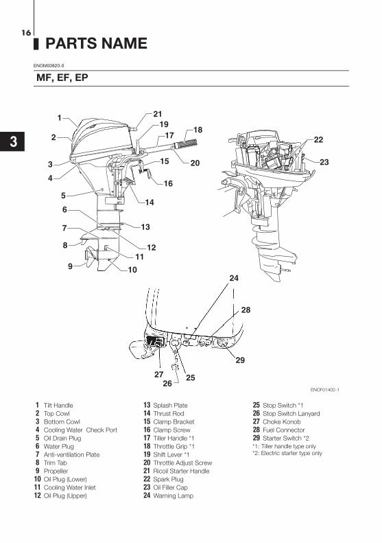
MF, EF, EP
1
2
3
4
5
8
9 10
1918
17
15
16
14
1211
25
23
2726
28
22
21
7 13
6
24
29
20
ENOF01402-1
1 Tilt Handle
2 Top Cowl
3 Bottom Cowl
4 Cooling Water Check Port
5 Oil Drain Plug
6 Water Plug
7 Anti-ventilation Plate
8 Trim Tab
9 Propeller
10 Oil Plug (Lower)
11 Cooling Water Inlet
12 Oil Plug (Upper)
13 Splash Plate
14 Thrust Rod
15 Clamp Bracket
16 Clamp Screw
17 Tiller Handle *1
18 Throttle Grip *1
19 Shift Lever *1
20 Throttle Adjust Screw
21 Ricoil Starter Handle
22 Spark Plug
23 Oil Filler Cap
24 Warning Lamp
25 Stop Switch *1
26 Stop Switch Lanyard
27 Choke Konob
28 Fuel Connector
29 Starter Switch *2
*1: Tiller handle type only*2: Electric starter type only
PARTS NAME 17
3
ENOM00020-0
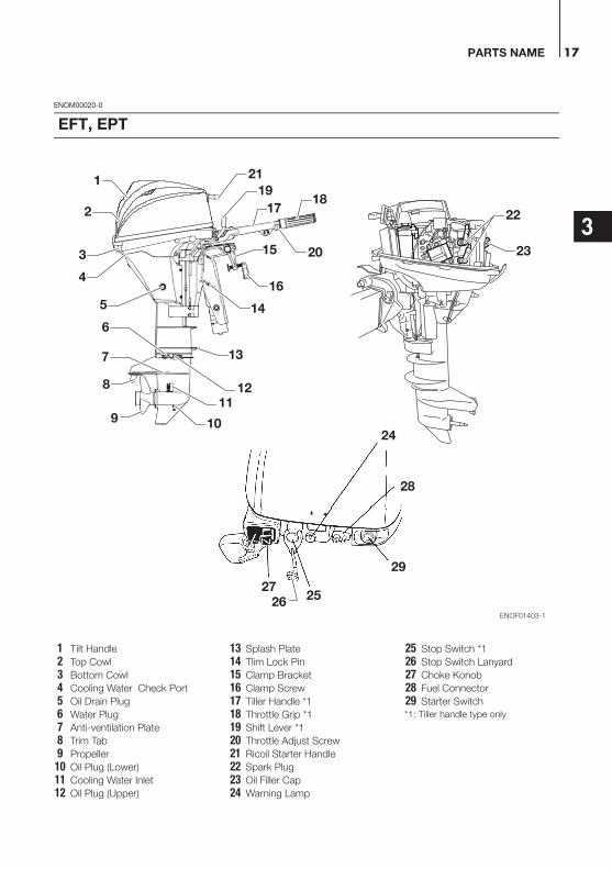
EFT, EPT
1
2
3
4
5
8
9 10
1211
2527
7
6
26
28
24
29
1918
17
15
16
14
23
22
21
13
20
ENOF01403-1
1 Tilt Handle
2 Top Cowl
3 Bottom Cowl
4 Cooling Water Check Port
5 Oil Drain Plug
6 Water Plug
7 Anti-ventilation Plate
8 Trim Tab
9 Propeller
10 Oil Plug (Lower)
11 Cooling Water Inlet
12 Oil Plug (Upper)
13 Splash Plate
14 Tlim Lock Pin
15 Clamp Bracket
16 Clamp Screw
17 Tiller Handle *1
18 Throttle Grip *1
19 Shift Lever *1
20 Throttle Adjust Screw
21 Ricoil Starter Handle
22 Spark Plug
23 Oil Filler Cap
24 Warning Lamp
25 Stop Switch *1
26 Stop Switch Lanyard
27 Choke Konob
28 Fuel Connector
29 Starter Switch
*1: Tiller handle type only
PARTS NAME18
33
1
2
4
5
67
8
109
14
13
12
11
ENOF01404-0
ENOM00822-0
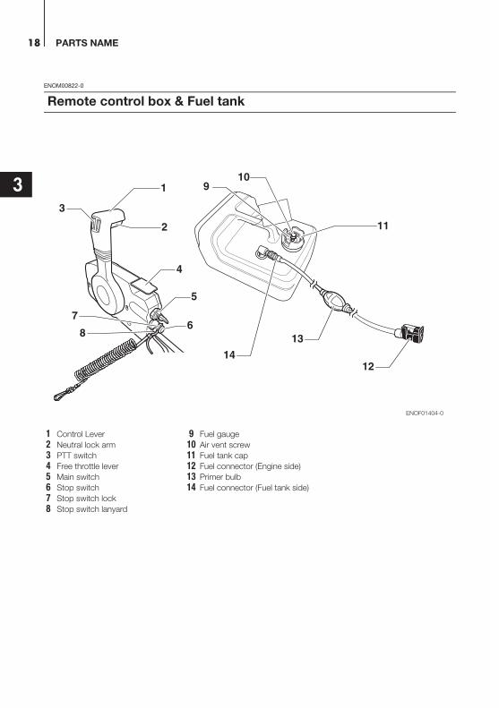
Remote control box & Fuel tank
1 Control Lever
2 Neutral lock arm
3 PTT switch
4 Free throttle lever
5 Main switch
6 Stop switch
7 Stop switch lock
8 Stop switch lanyard
9 Fuel gauge
10 Air vent screw
11 Fuel tank cap
12 Fuel connector (Engine side)
13 Primer bulb
14 Fuel connector (Fuel tank side)

19
4
LABEL LOCATIONS
ENOM00019-A
Warning label locations
8
7
6
1
2, 3
4
5
ENOF01405-1
LABEL LOCATIONS20
4
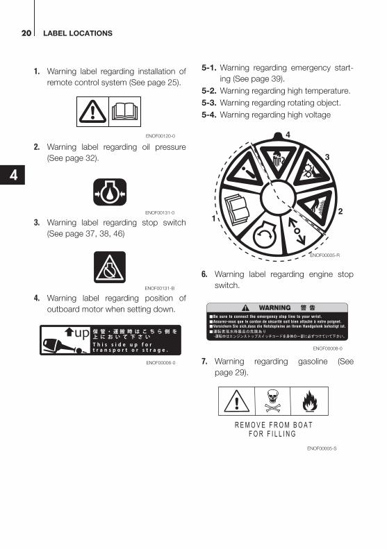
1. Warning label regarding installation of
remote control system (See page 25).
2. Warning label regarding oil pressure
(See page 32).
3. Warning label regarding stop switch
(See page 37, 38, 46)
4. Warning label regarding position of
outboard motor when setting down.
5-1. Warning regarding emergency start-
ing (See page 39).
5-2. Warning regarding high temperature.
5-3. Warning regarding rotating object.
5-4. Warning regarding high voltage
6. Warning label regarding engine stop
switch.
7. Warning regarding gasoline (See
page 29).
ENOF00120-0
ENOF00131-0
ENOF00131-B
ENOF00006-0
ENOF00005-R
12
3
4
ENOF00008-0
ENOF00005-S

LABEL LOCATIONS 21
4
8. Warning regarding gasoline (See
page 29).
ENOF00005-L
LABEL LOCATIONS22
4
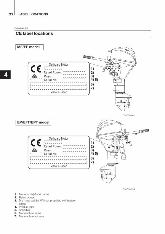
ENOM00019-B
1. Model code(Model name)2. Rated power3. Dry mass weight( Without propeller, with battery
cable)4. Product year5. Serial No.6. Manufacture name7. Manufacture address
CE label locations
:rewoP detaR
rotoM draobtuO
.oN laireS:ssaM
napaJ ni edaM
ENOF01406-1
2)3)4) 5)6)7)
1)
MF/EF model
:rewoP detaR
rotoM draobtuO
.oN laireS:ssaM
napaJ ni edaM
ENOF01406-A
2)3)4) 5)6)7)
1)
EP/EFT/EPT model
23
5
INSTALLATION
ENOM00024-B
ENOW00006-0
Most boats are rated and certified in terms
of their maximum allowable horsepower,
as shown on the boat’s certification plate.
Do not equip your boat with an outboard
motor that exceeds this limit. If in doubt,
contact your dealer.
Do not operate the outboard motor until it
has been securely mounted on the boat in
accordance with the instructions below.
ENOW00009-0
Mounting the outboard motor without
following this manual can lead to unsafe
conditions such as poor maneuverabil-
ity, lack of control or fire.
Loose clamp screws and/or mounting
bolts can lead to the release or displace-
ment of the outboard motor, possibly
resulting in lost of control and/or serious
personal injury. Be sure that fasteners
are tightened to the specified torque (30
N·m (3.0 kgf·m) 13 ft·lb). Check the fas-
teners for tightness from time to time.
Be sure to use outboard mounting fas-
teners included in the outboard motor
package or their equivalents in terms of
size, material, quality and strength.
Tighten fasteners to the specified torque
(30 N·m (3.0 kgf·m) 13 ft·lb). Test cruise
to check if fasteners are tightened
securely.
Outboard motor mounting must be per-
formed by trained service person(s)
using lift or hoist with sufficient capacity.
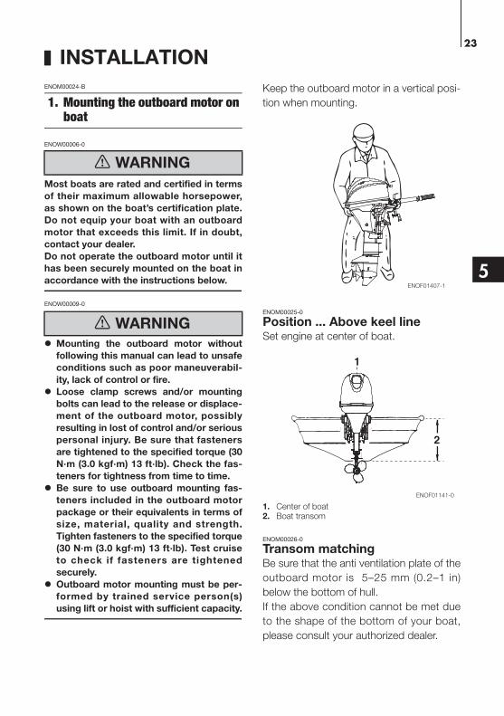
Keep the outboard motor in a vertical posi-
tion when mounting.
ENOM00025-0
Position ... Above keel lineSet engine at center of boat.
1. Center of boat2. Boat transom
ENOM00026-0
Transom matchingBe sure that the anti ventilation plate of the
outboard motor is 5–25 mm (0.2–1 in)
below the bottom of hull.
If the above condition cannot be met due
to the shape of the bottom of your boat,
please consult your authorized dealer.
1. Mounting the outboard motor on boat
WARNING
WARNING
ENOF01407-1
2
1
ENOF01141-0

INSTALLATION24
5
1. Bottom of hull2. Anti ventilation plate
ENOW00007-0
Before beginning the running test, check
that the boat with maximum capacity
loading floats on the water in a proper
attitude. Check the position of water
surface on the driveshaft housing. If the
water surface is near the bottom cowl-
ing, in high waves, water may enter the
engine cylinders.
Incorrect outboard motor mounting
height or existence of underwater
object(s), such as hull bottom design,
bottom surface conditions or underwa-
ter accessories, can cause water spray
possibly reaching the engine through an
opening of the bottom cowling during
cruising. Exposing the engine to such
conditions for extended periods can
lead to severe engine damage.
ENOM00830-A
Mounting bolts
Manual tilt type
1. To attach the outboard motor to the
boat, tighten the clamp screws by
turning their handles.
Also, use the bolts to secure the out-
board motor brackets on transom
board.
Secure the outboard motor with a rope
to prevent loss overboard.
ENON00002-0
Note
A rope is not included in the standard
accessories.
1. Bolt (8 × 85)2. Nut3. Washer4. Clamp screw
ENOW00945-0
Please inspect whether there is a loos-
ening of the clamp screw or mounting
bolts before departure.
Loosening may cause a dangerous situ-
ation, such as loss of control.
PTT type
1. To attach the outboard motor to the
boat, use the bolts to secure the out-
board motor brackets on transom
board.
1. Bolt (12 × 105)2. Washer (small diameter)3. Nut4. Washer (large diameter)
CAUTION
1
2
5−25 mm(0.2−1 in)
ENOF01408-0
CAUTION
1
4
2
3
ENOF00016-0
3
1
4
2ENOF00507-A

INSTALLATION 25
5
ENOW00008-A
Mounting bolts should be installed with
the bolt head at inside surface of the
transom. Mounting bolts installed with
the threaded end at the inside surface of
the transom can cause personal injury.
Tighten the bolts sufficiency, otherwise
falling down of outboard could be hap-
pened.
ENON00003-0
Notes
1. Apply sealing agent, such as silicone
sealed between the bolts and the tran-
som board holes before tightening the
bolts.
2. Be sure to tighten the mounting bolt
nuts to the specified torque.
(30 N·m (3.0 kgf·m) 13 ft·lb)
ENOM00840-0
ENOW00850-0
Remote control box location
1. Shift cable2. Throttle cable3. Cable harness B
Install the remote control box in a position
where it is easy to reach and operate the
controls.
Make sure there are no obstacles that can
interfere with the operation of the remote
control cable.
ENOW00850-0
Remote control cable lengthENOW00100-A
Be careful not to loop the remote control
cables to a diameter of 406 mm (16 in) or
less. Otherwise, it affects the service life of
the cable.
CAUTION
ENOF00508-0
2. Remote control device installation
CAUTION
3
1, 2
ENOF00841-0

INSTALLATION26
5
Measure the distance from the remote
control box to the outboard motor where
the remote control cable should be routed.
Prepare a cable that is 300-450mm (11.8-
17.7in) longer than the measured distance.
Temporari ly pul l the cable along the
intended cable route to check its length is
sufficient.
Connect the remote control cable to the
engine, then run the cable to the remote
control box, making sure it is not sharply
bent, too taut and free from obstructions
that could interfere with steering.
ENOM00029-A
ENOW00012-0
Battery electrolyte contains sulfuric acid
and thus is hazardous, causing a burn if it
comes in contact with your skin, or poison-
ous if swallowed.
Keep battery and electrolyte away from
reach of children
When handling the battery, be sure to:
Read all warnings shown on the battery
case
Prevent electrolyte from coming in con-
tact with any part of your body. Contact
can cause serious burn or, if it comes in
contact with your eye, loss of sight. Use
safety glasses and rubber gloves.
In case battery electrolyte comes in con-
tact with:
Skin, flush thoroughly with water.
Eye, flush thoroughly with water, and
then seek immediate medical treatment.
In case battery electrolyte is swallowed:
Seek immediate medical treatment.
ENOW00013-A
Battery generates explosive hydrogen gas.
Be sure to:
Charge the battery in a well-ventilated
place.
Place the battery away from any source
of fire, sparks and open flames such as
burners or welding equipment.
Do not smoke near the battery when the
battery is charging.
Do not charge the battery when the
electrolyte level is low. Otherwise, the
battery will be damaged and may cause
malfunction.
ENOW00014-0
Make sure that the battery leads do not
get stuck between the outboard motor
and boat when turning, etc.
The starter motor may fail to operate if
the leads are incorrectly connected.
Be sure to correctly connect the (+) and
(—) leads. If not, the charging system
will be damaged.
Do not disconnect the battery leads
from battery while the engine is operat-
ing, the electrical parts could be dam-
aged.
Always use a fully charged battery.
3. Battery installation
WARNING
ENOF00842-0
WARNING
CAUTION

INSTALLATION 27
5
ENOW00015-0
Do not use a battery that is not recom-
mended. Use of a battery not recom-
mended can lead to poor performance of,
and/or damage to, the electrical system.
ENON00006-A
Note
Recommended battery: 12V 40Ah/5HR,
350 (Cold Cranking Amps (CCA), In case of
cold whether: 12V 70Ah/5HR (650CCA))
Specifications and features of batteries vary
among the manufacturers. Consult the
manufacturer for details.
* The battery should be purchased sepa-
rately and is not supplied with the outboard
motor.
1. Place the battery box in a convenient
position away from possible water
spray. Securely fasten both the box
and the battery so they do not shake
loose.
2. Connect the positive lead (+) to the
positive terminal (+) of the battery, and
then connect the negative lead (—).
When disconnect ing the battery
always remove the negative lead (—)
first. After connecting the positive ter-
minal (+), securely place a cap on it to
prevent short circuits.
1. Battery cord (red)2. Battery cord (black)
CAUTION
2
1 ENOF00022-0
28
6
PRE-OPERATING PREPARATIONS
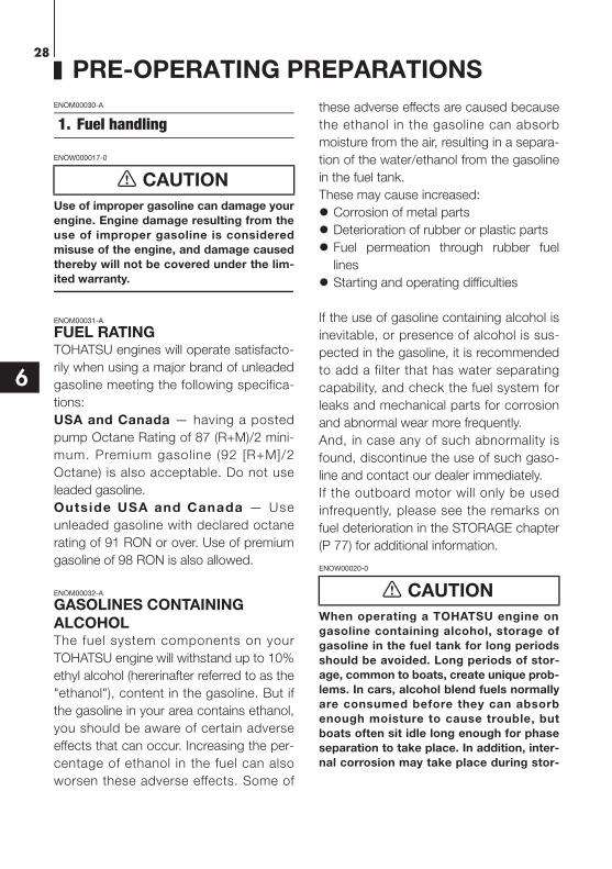
ENOM00030-A
ENOW000017-0
Use of improper gasoline can damage your
engine. Engine damage resulting from the
use of improper gasoline is considered
misuse of the engine, and damage caused
thereby will not be covered under the lim-
ited warranty.
ENOM00031-A
FUEL RATINGTOHATSU engines will operate satisfacto-
rily when using a major brand of unleaded
gasoline meeting the following specifica-
tions:
USA and Canada — having a posted
pump Octane Rating of 87 (R+M)/2 mini-
mum. Premium gasoline (92 [R+M]/2
Octane) is also acceptable. Do not use
leaded gasoline.
Outside USA and Canada — Use
unleaded gasoline with declared octane
rating of 91 RON or over. Use of premium
gasoline of 98 RON is also allowed.
ENOM00032-A
GASOLINES CONTAINING ALCOHOLThe fuel system components on your
TOHATSU engine will withstand up to 10%
ethyl alcohol (hererinafter referred to as the
"ethanol"), content in the gasoline. But if
the gasoline in your area contains ethanol,
you should be aware of certain adverse
effects that can occur. Increasing the per-
centage of ethanol in the fuel can also
worsen these adverse effects. Some of
these adverse effects are caused because
the ethanol in the gasoline can absorb
moisture from the air, resulting in a separa-
tion of the water/ethanol from the gasoline
in the fuel tank.
These may cause increased:
Corrosion of metal parts
Deterioration of rubber or plastic parts
Fuel permeation through rubber fuel
lines
Starting and operating difficulties
If the use of gasoline containing alcohol is
inevitable, or presence of alcohol is sus-
pected in the gasoline, it is recommended
to add a filter that has water separating
capability, and check the fuel system for
leaks and mechanical parts for corrosion
and abnormal wear more frequently.
And, in case any of such abnormality is
found, discontinue the use of such gaso-
line and contact our dealer immediately.
If the outboard motor will only be used
infrequently, please see the remarks on
fuel deterioration in the STORAGE chapter
(P 77) for additional information.
ENOW00020-0
When operating a TOHATSU engine on
gasoline containing alcohol, storage of
gasoline in the fuel tank for long periods
should be avoided. Long periods of stor-
age, common to boats, create unique prob-
lems. In cars, alcohol blend fuels normally
are consumed before they can absorb
enough moisture to cause trouble, but
boats often sit idle long enough for phase
separation to take place. In addition, inter-
nal corrosion may take place during stor-
1. Fuel handling
CAUTION
CAUTION

PRE-OPERATING PREPARATIONS 29
6
age if alcohol has washed protective oil
films from internal components.
ENOW00018-0
Fuel leakage can cause fire or explosion,
potentially leading to severe injury or loss
of life. Every fuel system part should be
checked periodically, and especially after
long term storage, for fuel leak, change of
hardness of rubber, expansion and/or cor-
rosion of metals. In case any indication of
fuel leakage or degradation of fuel part is
found, replace relevant part immediately
before continuing operation.
ENOM00043-B
ENOW00019-0
Do not fill the fuel tank over capacity. The
rise of gasoline temperature may cause
gasoline to expand which, if overfilled, may
leak through air vent screw when it is open.
Leaking gasoline is a dangerous fire haz-
ard.
ENOW00028-A
Consult an authorized dealer for details on
handling gasoline, if necessary.
Gasoline and its vapors are very flammable
and can be explosive.
When carrying a fuel tank containing gaso-
line:
Close the fuel tank cap and air vent
screw of fuel tank cap, or gasoline vapor
will be emitted through the air vent
screw, creating a fire hazard.
Do not smoke.
When or before refueling:
Be sure to remove the static electricity
charged in your body before refueling.
The sparks due to static electricity may
cause explosion of flammable gasoline.
Stop the engine, and do not start the
engine during refueling.
Do not smoke.
Be careful not to overfill fuel tank. Wipe
up any spilled gasoline immediately.
When or before cleaning the gasoline tank:
Dismount fuel tank from the boat.
Place the fuel tank away from every
source of ignition, such as sparks or
open flames.
Do the work outdoors or in a well venti-
lated area.
Wipe off gasoline well immediately if
spilled.
After cleaning gasoline tank:
Wipe off gasoline well immediately if
spilled.
If the fuel tank is disassembled for
cleaning, reassemble carefully. Imper-
fect assembly may cause a fuel leak,
possibly leading to fire or explosion.
Dispose aged or contaminated gasoline
in accordance with local regulations.
ENOW00029-A
When opening fuel tank cap, be sure to fol-
low the procedure described below. Fuel
could blast out through the fuel tank cap in
case the cap is loosened by using another
procedure when internal pressure of fuel
tank is raised by heat from sources such as
sun light.
ENOW0946-0
Separate tank must be fixed at appropriate
position so that well ventilated and tank
does not move or fall down while operat-
ing.
WARNING
2. Fuel filling
WARNING
WARNING WARNING
CAUTION
PRE-OPERATING PREPARATIONS30
6
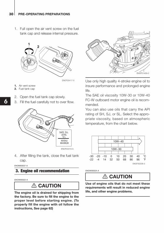
1. Full open the air vent screw on the fuel
tank cap and release internal pressure.
1. Air vent screw2. Fuel tank cap
2. Open the fuel tank cap slowly.
3. Fill the fuel carefully not to over flow.
4. After filling the tank, close the fuel tank
cap.
ENOM00037-A
ENOW00022-A
The engine oil is drained for shipping from
the factory. Be sure to fill the engine to the
proper level before starting engine. (To
properly fill the engine with oil follow the
instructions, See page 62)
Use only high quality 4-stroke engine oil to
insure performance and prolonged engine
life.
The SAE oil viscosity 10W-30 or 10W-40
FC-W outboard motor engine oil is recom-
mended.
You can also use oils that carry the API
rating of SH, SJ, or SL. Select the appro-
priate viscosity, based on atmospheric
temperature, from the chart below.
ENOW0002A-A
Use of engine oils that do not meet these
requirements will result in reduced engine
life, and other engine problems.
3. Engine oil recommendation
CAUTION
12
ENOF00417-0
SAFE FILLLEVEL12 L
NIVEAUMAXIMUM
ENOF00419-A
CAUTION
ENOF01409-0
10W−40
10W−30
˚C˚F
4096
3086
2068
1050
032
-1014
-20-4
-30-22
ENOF00208-0
PRE-OPERATING PREPARATIONS 31
6
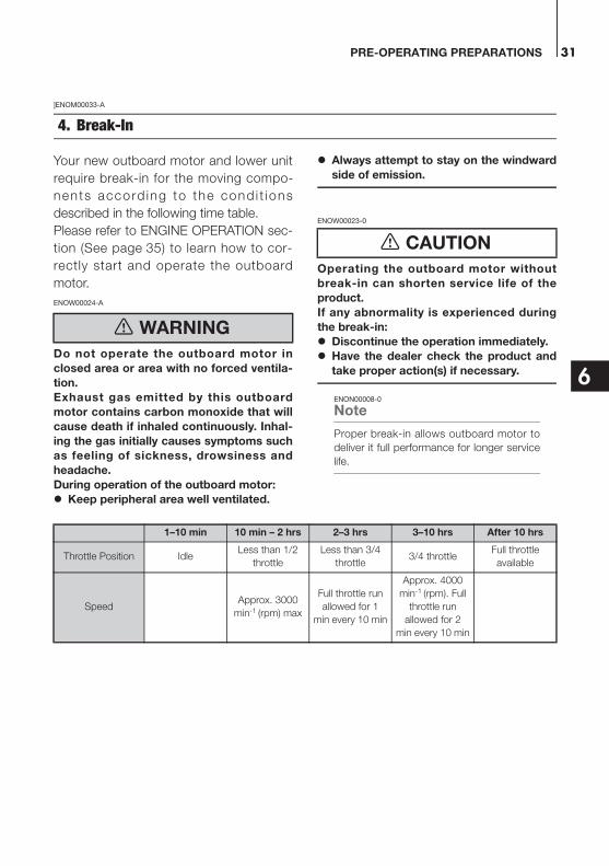
]ENOM00033-A
Your new outboard motor and lower unit
require break-in for the moving compo-
nents accord ing to the cond i t ions
described in the following time table.
Please refer to ENGINE OPERATION sec-
tion (See page 35) to learn how to cor-
rectly start and operate the outboard
motor.
ENOW00024-A
Do not operate the outboard motor in
closed area or area with no forced ventila-
tion.
Exhaust gas emitted by this outboard
motor contains carbon monoxide that will
cause death if inhaled continuously. Inhal-
ing the gas initially causes symptoms such
as feeling of sickness, drowsiness and
headache.
During operation of the outboard motor:
Keep peripheral area well ventilated.
Always attempt to stay on the windward
side of emission.
ENOW00023-0
Operating the outboard motor without
break-in can shorten service life of the
product.
If any abnormality is experienced during
the break-in:
Discontinue the operation immediately.
Have the dealer check the product and
take proper action(s) if necessary.
ENON00008-0
Note
Proper break-in allows outboard motor to
deliver it full performance for longer service
life.
4. Break-In
WARNING
CAUTION
1–10 min 10 min – 2 hrs 2–3 hrs 3–10 hrs After 10 hrs
Throttle Position IdleLess than 1/2
throttle
Less than 3/4
throttle3/4 throttle
Full throttle
available
SpeedApprox. 3000
min-1 (rpm) max
Full throttle run
allowed for 1
min every 10 min
Approx. 4000
min-1 (rpm). Full
throttle run
allowed for 2
min every 10 min
PRE-OPERATING PREPARATIONS32
6
ENOM00039-0
If outboard motor encounters an abnormal
condition of fault, the warning horn will
emit a continuous beep or intermittent
short beeps and the warning lamp (LED)
will synchronize with the horn and engine
speed will be limited (engine will not be
stopped).
See next page for conditions which will
lead to an abnormal condition or fault.
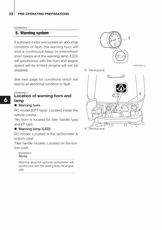
ENOM00040-C
Location of warning horn and lamp
Warning horn
RC model (EPT type): Located inside the
remote control.
*No horn is located for tiller handle type
and EP type.
Warning lamp (LED)
RC model: Located in the tachometer &
bottom cowl.
Tiller handle models: Located on the bot-
tom cowl.
ENON00009-A
Note
Warning lamp for optional tachometer will
synchronize with the waring lamp for engine
side.
1. Warning lamp
1. Warning lamp
5. Warning system1
ENOF00851-A
ENOF01410-1
1

PRE-OPERATING PREPARATIONS 33
6
ENOM00041-C
Warning indicators, faults and remedy
Remarks
*1: In this case, oil pressure switch is “ON”.
*2: It is necessary to stop the engine, if you want to stop the working indicators and re-set the warning system.
High speed ESG (Electronic Safety Governor)High speed ESG is a device to prevent over revolution of the engine. If the load to the engine becomes light for some
reason, it runs at a higher speed than the usual. In such the case, and the ESG is activated not to ignite the spark
plug, therefore, the engine speed varies and be controlled under 6300 min-1 (rpm).
Low speed ESGLow speed ESG is a device to prevent the engine from getting damage. If the engine has problems regarding oil
pressure, the low speed ESG is activated not to ignite the spark plug, the engine speed varies and be controlled
under 2800 min-1 (rpm).
Warning indicators
Description of faults RemedySound(EPT only)
Lamp (LED) ESG
-On for several
sec.- Normal system test when start up
- - High speed ESGEngine speed exceeds maximum
allowable RPM1
Continuous*2 ON*2 Low speed ESG Low oil pressure*1 2
PRE-OPERATING PREPARATIONS34
6
Remedy
1. Reduce the throttle to less than half
opening, and move to safe place
quickly, and stop the engine.
Check the propeller for bent or dam-
aged blades.
Consult an authorized dealer if engine
shows the same result even after
replacing propeller with new one.
2. Move to safe place quickly, and stop
the engine.
Check the engine oil level, and add
engine oil if necessary.
Consult your dealer if the engine oil
level is too low or too high.
ENOW00025-A
Low speed ESG ON: Engine speed will
be limited to 2800 min-1 (rpm), however
you should not continue to run engine.
High speed ESG ON: Engine speed will
be l imited to 6300 min-1 (rpm) and
engine will run rough until throttle is
reduced.
CAUTION

35
7
ENGINE OPERATION
ENOM00042-0
ENOW00022-A
The engine oil is drained for shipping from
the factory. Be sure to fill the engine to the
proper level before starting engine. (Toproperly fill the engine with oil follow the
instructions. See page 62)
ENOW00027-A
Before starting engine for the first time
after reassembling engine or off-season
storage, disconnect stop switch lock andcrank approximately 10 times in order to
prime the oil pump.
ENOM00044-A
ENOW00029-A
When opening fuel tank cap, be sure to fol-
low the procedure described below. Fuelcould blast out through the fuel tank cap in
case the cap is loosened by using another
procedure when internal pressure of fuel
tank is raised by heat from sources such as
sun light.
ENOW0947-0
When using a separate tank, be sure that
the fuel line is not kinked and is connected
securely.
1. Full open the air vent screw on the fuel
tank cap.
1. Air vent screw2. Fuel tank cap
2. Open the fuel tank cap slowly and
release internal pressure completely.
After that, close the fuel tank.
3. Connect the fuel connector to the
engine and fuel tank.
1. Fuel connector2. Push3. Insert
Before starting
CAUTION
CAUTION
1. Fuel feeding
WARNING
ENOF01409-0
CAUTION
12
ENOF00417-0
1
22233
ENOF00514-0
ENGINE OPERATION36
7
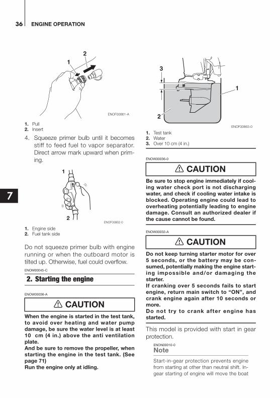
1. Pull2. Insert
4. Squeeze primer bulb until it becomes
stiff to feed fuel to vapor separator.
Direct arrow mark upward when prim-
ing.
1. Engine side2. Fuel tank side
Do not squeeze primer bulb with engine
running or when the outboard motor is
tilted up. Otherwise, fuel could overflow.
ENOM00045-C
ENOW00036-A
When the engine is started in the test tank,
to avoid over heating and water pump
damage, be sure the water level is at least10 cm (4 in.) above the anti ventilation
plate.
And be sure to remove the propeller, whenstarting the engine in the test tank. (See
page 71)
Run the engine only at idling.
1. Test tank2. Water3. Over 10 cm (4 in.)
ENOW00036-0
Be sure to stop engine immediately if cool-
ing water check port is not discharging
water, and check if cooling water intake isblocked. Operating engine could lead to
overheating potentially leading to engine
damage. Consult an authorized dealer ifthe cause cannot be found.
ENOW00032-A
Do not keep turning starter motor for over
5 seconds, or the battery may be con-sumed, potentially making the engine start-
ing impossible and/or damaging the
starter. If cranking over 5 seconds fails to start
engine, return main switch to “ON”, and
crank engine again after 10 seconds or
more.Do not try to crank after engine has
started.
This model is provided with start in gear
protection.
ENON00010-0
Note
Start-in-gear protection prevents engine
from starting at other than neutral shift. In-
gear starting of engine will move the boat
2. Starting the engine
CAUTION
12
ENOF00861-A
1
2ENOF00862-0
CAUTION
CAUTION
1
3
2
ENOF00863-0
ENGINE OPERATION 37
7
immediately, potentially leading to falling
down or causing passenger(s) to be thrown
overboard.
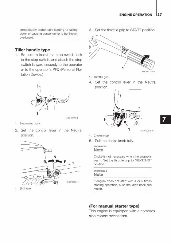
Tiller handle type1. Be sure to install the stop switch lock
to the stop switch, and attach the stop
switch lanyard securely to the operator
or to the operator's PFD (Personal Flo-
tation Device.)
1. Stop switch lock
2. Set the control lever in the Neutral
position.
1. Shift lever
3. Set the throttle grip to START position.
1. Throttle grip
4. Set the control lever in the Neutral
position.
1. Choke knob
5. Pull the choke knob fully.
ENON00501-0
Note
Choke is not necessary when the engine is
warm. Set the throttle grip to “RE-START”
position.
ENON00502-0
Note
If engine does not start with 4 or 5 times
starting operation, push the knob back and
restart.
(For manual starter type)This engine is equipped with a compres-
sion release mechanism.
1ENOF00516-0
RN
F
ENOF00531-1
1
1ENOF01107-0
1 ENOF00518-0
ENGINE OPERATION38
7
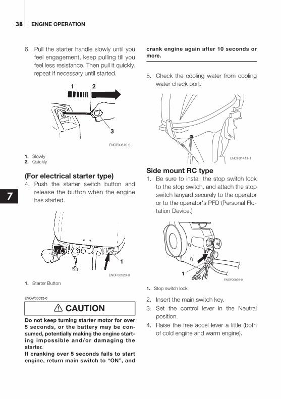
6. Pull the starter handle slowly until you
feel engagement, keep pulling till you
feel less resistance. Then pull it quickly.
repeat if necessary until started.
1. Slowly2. Quickly
(For electrical starter type)4. Push the starter switch button and
release the button when the engine
has started.
1. Starter Button
ENOW00032-0
Do not keep turning starter motor for over
5 seconds, or the battery may be con-
sumed, potentially making the engine start-
ing impossible and/or damaging the
starter.
If cranking over 5 seconds fails to start
engine, return main switch to “ON”, and
crank engine again after 10 seconds or
more.
5. Check the cooling water from cooling
water check port.
Side mount RC type1. Be sure to install the stop switch lock
to the stop switch, and attach the stop
switch lanyard securely to the operator
or to the operator's PFD (Personal Flo-
tation Device.)
1. Stop switch lock
2. Insert the main switch key.
3. Set the control lever in the Neutral
position.
4. Raise the free accel lever a little (both
of cold engine and warm engine).
CAUTION
1 2
3
ENOF00519-0
ENOF00520-0
1
ENOF01411-1
1ENOF00869-0

ENGINE OPERATION 39
7
1. Neutral (N)2. Control lever3. Fully open (Forward)4. Fully open (Reverse)5. Free throttle lever6. Main switch key7. Stop switch
ENON00035-A
Note
The free throttle lever can not be raised
when the control lever shift is in Forward or
Reverse.
5. Turn the main switch key to ON posi-
tion. Then, continuously push the key
to operate the choke.
ENON00503-0
Note
Choke operation is not necessary if the
engine is warm.
1. ON2. START3. OFF4. Push to operate choke knob.
6. Stop pushing the key when the engine
has started.
The key returns to the original position,
automatically.
7. Returns the Free accel lever to close
position.
8. Confirm warning lamp light up and
then go off after engine has started.
1. Warning lamp
9. Check the cooling water from cooling
water check port.
ENOM00042-A
Emergency startingENOW00099-A
When the emergency starter rope is used
for starting engine;
Start in gear protection does not work.
Be sure to shift is at neutral position.
Otherwise the engine will move the boat
immediately and cause personal injury.
Be careful that your clothes or other
items do not get caught in the rotating
engine parts.
NRF
1 2
3
4
5
6
7ENOF00870-0
1
23
4
ENOF00871-A
WARNING
1
ENOF00851-A
ENOF01411-1
ENGINE OPERATION40
7
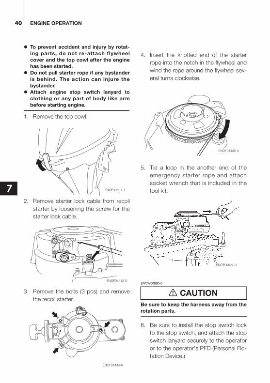
To prevent accident and injury by rotat-
ing parts, do not re-attach flywheel
cover and the top cowl after the engine
has been started.
Do not pull starter rope if any bystander
is behind. The action can injure the
bystander.
Attach engine stop switch lanyard to
clothing or any part of body like arm
before starting engine.
1. Remove the top cowl.
2. Remove starter lock cable from recoil
starter by loosening the screw for the
starter lock cable.
3. Remove the bolts (3 pcs) and remove
the recoil starter.
4. Insert the knotted end of the starter
rope into the notch in the flywheel and
wind the rope around the flywheel sev-
eral turns clockwise.
5. Tie a loop in the another end of the
emergency starter rope and attach
socket wrench that is included in the
tool kit.
ENOW00860-0
Be sure to keep the harness away from the
rotation parts.
6. Be sure to install the stop switch lock
to the stop switch, and attach the stop
switch lanyard securely to the operator
or to the operator's PFD (Personal Flo-
tation Device.)
ENOF00521-1
ENOF01412-0
ENOF01434-0
CAUTION
ENOF01435-0
ENOF00527-0

ENGINE OPERATION 41
7
7. Set the control lever in the Neutral
position.
8. Pull the starter handle slowly until you
feel engagement, keep pulling till you
feel less resistance. Then pull it quickly.
9. After engine starts, do not reinstall fly-
wheel cover and top cowl.
ENOM00518-0
If the choke solenoid fails to operate (EP and EPT type only)
1. Remove the top cowl.
2. Close the choke plate by finger.
3. Raise the Free accel lever a little.
4. Turn the main switch key to start posi-
tion.
5. Stop pushing the key when the engine
has started.
6. Return the choke plate to open posi-
tion.
1. Choke plate (open position)
1. Choke plate (closed position)
ENOM00043-A
ENOW00932-0
Be sure to check that cooling water is
coming out of the cooling water check port
during warm up.
Warm the engine at low engine speeds for
about
3 minutes : above 5°C (41°F)
5 minutes at 2000 min-1 (rpm) : blow 5°C
(41°F)
This allows the lubricating oil to circulate to
all parts of the engine. Operating the
engine without warm up shortens the
engine's life.
1
ENOF00528-0
3. Warming up the engine
CAUTION
1
ENOF00529-0
ENOF01411-1
ENGINE OPERATION42
7
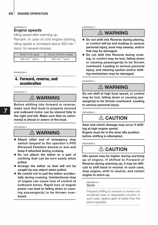
ENOM00044-0
Engine speedsIdling speed after warming up.
Remark: In case of cold engine starting,
idling speed is increased about 400 min-1
(rpm) for several minutes.
ENOM00046-A
ENOW00037-0
Before shifting into forward or reverse,
make sure that boat is properly moored
and outboard motor can be steered fully to
the right and left. Make sure that no swim-
mer(s) is ahead or astern of the boat.
ENOW00038-A
Attach other end of emergency stop
switch lanyard to the operator's PFD
(Personal Flotation device) or arm and
keep it attached during cruising.
Do not attach the tether to a part of
clothing that can be torn easily when
pulled.
Arrange the tether so that will not be
caught by any object when pulled.
Be careful not to pull the tether acciden-
tally during cruising. Unintentional stop
of engine can cause loss of control of
outboard motor. Rapid loss of engine
power can lead to falling down or caus-
ing passenger(s) to be thrown over-
board.
ENOW00042-0
Do not shift into Reverse during planing,
or control will be lost leading to serious
personal injury, boat may swamp, and/or
hull may be damaged.
Do not shift into Reverse during cruis-
ing, or control may be lost, falling down
or causing passenger(s) to be thrown
overboard. Leading to serious personal
injury, and steering system and/or shift-
ing mechanism may be damaged.
ENOW00861-0
Do not shift at high boat speed, or control
may be lost, falling down or causing pas-
senger(s) to be thrown overboard. Leading
to serious personal injury.
ENOW00862-0
Gear and clutch damage may occur if shift-
ing at high engine speed.
Engine must be in the slow idle position
before shifting is attempted.
ENOW00863-0
Idle speed may be higher during warming
up of engine. If shifted to Forward or
Reverse during warming up, it may be diffi-
cult to shift back to neutral. In such case,
stop engine, shift to neutral, and restart
engine to warm up.
ENON00014-0
Note
Frequent shifting to forward or reverse can
accelerate wear or degradation of parts. In
such case, replace gear oil earlier than the
period specified.
Clutch in (In gear) Clutch off (Out of gear)
900 min-1 (rpm) 950 min-1 (rpm)
4. Forward, reverse, and acceleration
WARNING
WARNING
WARNING
WARNING
CAUTION
CAUTION
ENGINE OPERATION 43
7
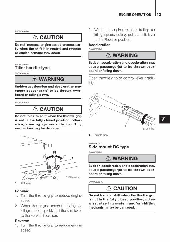
ENOW00864-0
Do not increase engine speed unnecessar-
ily when the shift is in neutral and reverse,
or engine damage may occur.
ENOM00890-A
Tiller handle typeENOW00867-0
Sudden acceleration and deceleration may
cause passenger(s) to be thrown over-
board or falling down.
ENOW00865-A
Do not force to shift when the throttle grip
is not in the fully closed position, other-
wise, steering system and/or shifting
mechanism may be damaged.
1. Shift lever
Forward
1. Turn the throttle grip to reduce engine
speed.
2. When the engine reaches trolling (or
idling) speed, quickly pull the shift lever
to the Forward position.
Reverse
1. Turn the throttle grip to reduce engine
speed.
2. When the engine reaches trolling (or
idling) speed, quickly pull the shift lever
to the Reverse position.
AccelerationENOW00867-0
Sudden acceleration and deceleration may
cause passenger(s) to be thrown over-
board or falling down.
Open throttle grip or control lever gradu-
ally.
1. Throttle grip
ENOM0900-0
Side mount RC typeENOW00867-0
Sudden acceleration and deceleration may
cause passenger(s) to be thrown over-
board or falling down.
ENOW00865-A
Do not force to shift when the throttle grip
is not in the fully closed position, other-
wise, steering system and/or shifting
mechanism may be damaged.
CAUTION
WARNING
CAUTION
RN
F
ENOF00531-A
1
WARNING
WARNING
CAUTION
ENOF01119-01
ENGINE OPERATION44
7
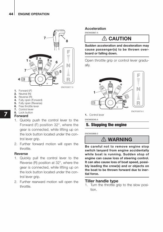
1. Forward (F)2. Neutral (N)3. Reverse (R)4. Fully open (Forward)5. Fully open (Reverse)6. Free throttle lever7. Control lever8. Lock button
Forward
1. Quickly push the control lever to the
Forward (F) position 32°, where the
gear is connected, while lifting up on
the lock button located under the con-
trol lever grip.
2. Further forward motion will open the
throttle.
Reverse
1. Quickly pull the control lever to the
Reverse (R) position at 32°, where the
gear is connected, while lifting up on
the lock button located under the con-
trol lever grip.
2. Further rearward motion will open the
throttle.
AccelerationENOW00867-A
Sudden acceleration and deceleration may
cause passenger(s) to be thrown over-
board or falling down.
Open throttle grip or control lever gradu-
ally.
1. Control lever
ENOM00049-A
ENOW00868-0
Be careful not to remove engine stop
switch lanyard from engine accidentally
while boat is running. Sudden stop of
engine can cause loss of steering control.
It can also cause loss of boat speed, possi-
bly leading the crew(s) and or objects on
the boat to be thrown forward due to iner-
tial force.
Tiller handle type1. Turn the throttle grip to the slow posi-
tion.
NRF
78
12
3
4
57
6
ENOF00877-0
CAUTION
5. Stopping the engine
WARNING
NRF
1
ENOF00879-0
ENGINE OPERATION 45
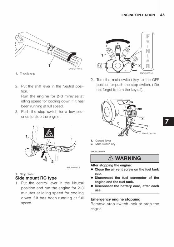
7
1. Throttle grip
2. Put the shift lever in the Neutral posi-
tion.
Run the engine for 2-3 minutes at
idling speed for cooling down if it has
been running at full speed.
3. Push the stop switch for a few sec-
onds to stop the engine.
1. Stop Switch
Side mount RC type1. Put the control lever in the Neutral
position and run the engine for 2-3
minutes at idling speed for cooling
down if it has been running at full
speed.
2. Turn the main switch key to the OFF
position or push the stop switch. ( Do
not forget to turn the key off).
1. Control lever2. Mine switch key
ENOW00869-0
After stopping the engine:
Close the air vent screw on the fuel tank
cap.
Disconnect the fuel connector of the
engine and the fuel tank.
Disconnect the battery cord, after each
use.
Emergency engine stopping
Remove stop switch lock to stop the
engine.
1ENOF01107-0
1
2
ENOF00569-1
WARNING
NRF
2
1
ENOF00881-0
ON
OFFSTART
2
ENOF00882-0
ENGINE OPERATION46
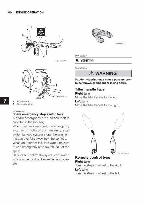
7 1. Stop switch2. Stop switch lock
ENOM00910-0
Spare emergency stop switch lock
A spare emergency stop switch lock is
provided in the tool bag.
When used as described, the emergency
stop switch clip and emergency stop
switch lanyard system stops the engine if
the operator falls away from the controls.
When an operator falls into water, be sure
to use emergency stop switch lock of the
spare.
Be sure to confirm the spare stop switch
lock is in the tool bag before begin to oper-
ate.
ENOM00920-0
ENOW00870-0
Sudden steering may cause passenger(s)
to be thrown overboard or falling down.
Tiller handle typeRight turn
Move the tiller handle to the left
Left turn
Move the tiller handle to the right.
Remote control typeRight turn
Turn the steering wheel to the right.
Left turn
Turn the steering wheel to the left.
1
2ENOF00569-C
1
2
ENOF00884-0
6. Steering
WARNING
ENOF00891-0
ENOF00892-0
ENGINE OPERATION 47
7
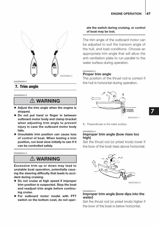
ENOM00050-0
ENOW00043-A
Adjust the trim angle when the engine is
stopped.
Do not put hand or finger in between
outboard motor body and clamp bracket
when adjusting trim angle to prevent
injury in case the outboard motor body
falls.
Unsuitable trim position can cause loss
of control of boat. When testing a trim
position, run boat slow initially to see if it
can be controlled safely.
ENOW00044-0
Excessive trim up or down may lead to
unstable boat operation, potentially caus-
ing the steering difficulty that leads to acci-
dent during cruising.
Do not cruise at high speed if improper
trim position is suspected. Stop the boat
and readjust trim angle before continu-
ing cruise.
For outboard motor model with PTT
switch on the bottom cowl, do not oper-
ate the switch during cruising, or control
of boat may be lost.
The trim angle of the outboard motor can
be adjusted to suit the transom angle of
the hull, and load conditions. Choose an
appropriate trim angle that will allow the
anti-ventilation plate to run parallel to the
water surface during operation.
ENOM00052-0
Proper trim angle
The position of the thrust rod is correct if
the hull is horizontal during operation.
1. Perpendicular to the water surface
ENOM00053-A
Improper trim angle (bow rises too high)
Set the thrust rod (or priset knob) lower if
the bow of the boat rises above horizontal.
ENOM00054-0
Improper trim angle (bow dips into the water)
Set the thrust rod (or priset knob) higher if
the bow of the boat is below horizontal.
7. Trim angle
WARNING
WARNING
ENOF00893-0
1
ENOF00051-1
ENOF00052-0
ENGINE OPERATION48
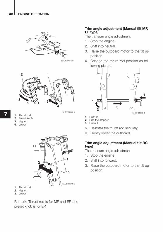
7 1. Thrust rod2. Preset knob3. Higher4. Lower
1. Thrust rod2. Higher3. Lower
Remark: Thrust rod is for MF and EF, and
preset knob is for EP.
Trim angle adjustment (Manual tilt MF, EF type)
The transom angle adjustment
1. Stop the engine.
2. Shift into neutral.
3. Raise the outboard motor to the tilt up
position.
4. Change the thrust rod position as fol-
lowing picture.
1. Push in2. Rise the stopper3. Pull out
5. Reinstall the thurst rod securely.
6. Gentry lower the outboard.
Trim angle adjustment (Manual tilt RC type)
The transom angle adjustment
1. Stop the engine
2. Shift into forward.
3. Raise the outboard motor to the tilt up
position.
ENOF00053-0
2
234
1
33
4
ENOF00532-0
3
22
ENOF00674-B
1
32
1
ENOF01238-1
ENGINE OPERATION 49
7
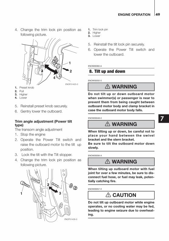
4. Change the trim lock pin position as
following picture.
1. Preset knob
2. Pull3. Higher4. Lower
5. Reinstall preset knob securely.
6. Gentry lower the outboard.
Trim angle adjustment (Power tilt type)
The transom angle adjustment
1. Stop the engine
2. Operate the Power Tilt switch and
raise the outboard motor to the tilt up
position.
3. Lock the tilt with the Tilt stopper.
4. Change the trim lock pin position as
following picture.
1. Trim lock pin2. Higher3. Lower
5. Reinstall the tilt lock pin securely.
6. Operate the Power Tilt switch and
lower the outboard.
ENOM00060-A
ENOW00055-0
Do not tilt up or down outboard motor
when swimmer(s) or passenger is near to
prevent them from being caught between
outboard motor body and clamp bracket in
case the outboard motor body falls.
ENOW00048-0
When tilting up or down, be careful not to
place your hand between the swivel
bracket and the stern bracket.
Be sure to tilt the outboard motor down
slowly.
ENOW00056-A
When tilting up outboard motor with fuel
joint for over a few minutes, be sure to dis-
connect fuel hose, or fuel may leak, poten-
tially catching fire.
ENOW00057-0
Do not tilt up outboard motor while engine
operates, or no cooling water may be fed,
leading to engine seizure due to overheat-
ing.
4
1
23 2
ENOF01425-0
31
22
ENOF01426-0
8. Tilt up and down
WARNING
WARNING
WARNING
CAUTION
ENGINE OPERATION50
7
ENON00921-0
Note
Before tilting the outboard motor up, after
stopping the motor leave it in the running
position for about a minute to allow water to
drain from inside the engine.
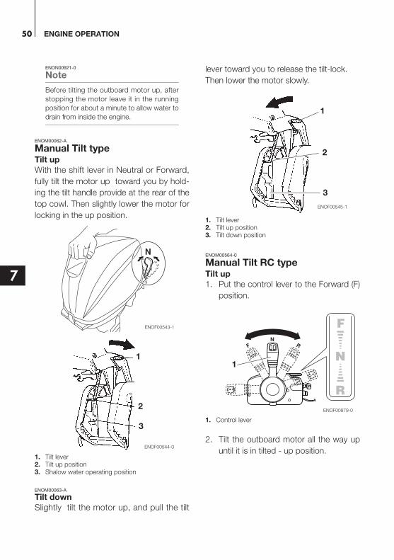
ENOM00062-A
Manual Tilt typeTilt up
With the shift lever in Neutral or Forward,
fully tilt the motor up toward you by hold-
ing the tilt handle provide at the rear of the
top cowl. Then slightly lower the motor for
locking in the up position.
1. Tilt lever2. Tilt up position3. Shalow water operating position
ENOM00063-A
Tilt down
Slightly tilt the motor up, and pull the tilt
lever toward you to release the tilt-lock.
Then lower the motor slowly.
1. Tilt lever2. Tilt up position3. Tilt down position
ENOM00564-0
Manual Tilt RC typeTilt up
1. Put the control lever to the Forward (F)
position.
1. Control lever
2. Tilt the outboard motor all the way up
until it is in tilted - up position.
N
ENOF00543-1
1
2
3
ENOF00544-0
1
2
3
ENOF00545-1
NRF
1
ENOF00879-0

ENGINE OPERATION 51
7
1. Tilt up position
3. Set the knob to Lock position, then
secure the tilt locking.
1. LOCK
2. UN-LOCK
Tilt down
1. Set the knob to Unlock position.
1. LOCK
2. UN-LOCK
2. Lift up the outboard motor slightly until
it is in Release position, and then out-
board motor tilted down.
1. Tilt release position
ENOM00069-B
Power Tilt typeTilt up
1. Operate the Power Tilt switch and tilt
the outboard motor up.
2. Lock the tilt with the Tilt stopper after
the outboard motor has been tilted up
Tilt down
1. Release the tilt stopper from the set-up
position while slightly tilting up out-
board motor.
2. Operate the Power Tilt switch and tilt
the outboard motor down until the
motor touches to the thrust rod.
1
JNOF01403-1
1
2
JNOF01404-0
1
2
JNOF01405-0
1JNOF01406-1
UP
UPDN
DN
ENOF00067-B
ENGINE OPERATION52
7
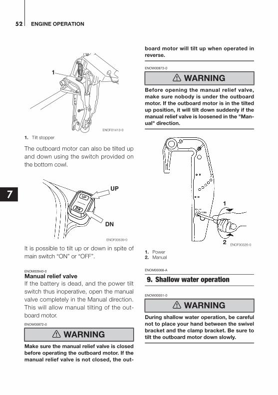
1. Tilt stopper
The outboard motor can also be tilted up
and down using the switch provided on
the bottom cowl.
It is possible to tilt up or down in spite of
main switch “ON” or “OFF”.
ENOM00940-0
Manual relief valve
If the battery is dead, and the power tilt
switch thus inoperative, open the manual
valve completely in the Manual direction.
This will allow manual tilting of the out-
board motor.
ENOW00872-0
Make sure the manual relief valve is closed
before operating the outboard motor. If the
manual relief valve is not closed, the out-
board motor will tilt up when operated in
reverse.
ENOW00873-0
Before opening the manual relief valve,
make sure nobody is under the outboard
motor. If the outboard motor is in the tilted
up position, it will tilt down suddenly if the
manual relief valve is loosened in the "Man-
ual" direction.
1. Power2. Manual
ENOM00068-A
ENOW00051-0
During shallow water operation, be careful
not to place your hand between the swivel
bracket and the clamp bracket. Be sure to
tilt the outboard motor down slowly. WARNING
1
ENOF01413-0
UP
DN
ENOF00539-0
WARNING
9. Shallow water operation
WARNING
1
2ENOF00326-0

ENGINE OPERATION 53
7
ENOW00053-0
While in shallow water drive position, do
not operate the outboard motor in Reverse.
Operate the outboard motor at slow speed
and keep the cooling water intake sub-
merged.
ENOW00054-A
Do not overtilt outboard motor when driv-
ing shallow water, or air may be sucked
through water inlet, potentially leading to
engine overheating.
1. Water inlet
Manual tilt type (MF, EF type)Shallow water running position:
1. With the shift lever in Neutral or For-
ward, tilt the motor up slowly by about
40° and then lower the tilt lever for set-
ting at the shallow water running posi-
tion.
Return to normal running position:
2. Tilt the motor up fully and then return
the motor down slowly to the normal
running position.
1. Tilt lever2. Shallow water running position
ENOM00541-A
Manual tilt type (EP type)
Shallow water running position1. Stop the engine.
2. Shift the outboard into forward.
3. Tilt the outboard up to one of the shal-
low water positions.
1. Shallow water drive position
Return to normal running
position1. Stop the engine.
2. Tilt the outboard up to the tilt release
position.
CAUTION
CAUTION
1
ENOF01144-A
1
2
ENOF00549-0
1
ENOF00550-1

ENGINE OPERATION54
7
3. Gently lower the outboard.
1. Tilt release position
ENOM00069-A
Power Tilt type1. Operate the Power Tilt switch and tilt
the outboard motor up into desired
shallow water running position.
1
ENOF00551-1
UPDN
ENOF00343-A
UP
DN
ENOF00067-0
55
8
REMOVING AND CARRYING THE OUTBOARD MOTOR
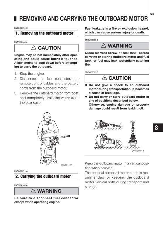
ENOM00070-C
ENOW00064-0
Engine may be hot immediately after oper-
ating and could cause burns if touched.
Allow engine to cool down before attempt-
ing to carry the outboard.
1. Stop the engine.
2. Disconnect the fuel connector, the
remote control cables and the battery
cords from the outboard motor.
3. Remove the outboard motor from boat
and completely drain the water from
the gear case.
ENOM00071-A
ENOW00933-0
Be sure to disconnect fuel connector
except when operating engine.
Fuel leakage is a fire or explosion hazard,
which can cause serious injury or death.
ENOW00065-0
Close air vent screw of fuel tank before
carrying or storing outboard motor and fuel
tank, or fuel may leak, potentially catching
fire.
ENOW00066-0
Do not give a shock to an outboard
motor during transportation. It becames
a cause of breakage.
Do not carry or store outboard motor in
any of positions described below.
Otherwise, engine damage or property
damage could result from leaking oil.
Keep the outboard motor in a vertical posi-
tion when carrying.
The optional outboard motor stand is rec-
ommended for keeping the outboard
motor vertical both during transport and
storage.
1. Removing the outboard motor
CAUTION
2. Carrying the outboard motor
WARNING
ENOF01407-1
WARNING
CAUTION
ENOF01414-1
REMOVING AND CARRYING THE OUTBOARD MOTOR56
8
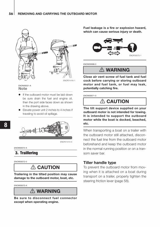
ENON00021-A
Note
If the outboard motor must be laid down
be sure drain the fuel and engine oil,
then the port side faces down as shown
in the drawing above.
Elevate power unit 2 inches to 4 inches if
traveling to avoid oil spillage.
ENOM00072-A
ENOW00072-0
Trailering in the tilted position may cause
damage to the outboard motor, boat, etc.
ENOW00073-A
Be sure to disconnect fuel connector
except when operating engine.
Fuel leakage is a fire or explosion hazard,
which can cause serious injury or death.
ENOW00068-0
Close air vent screw of fuel tank and fuel
cock before carrying or storing outboard
motor and fuel tank, or fuel may leak,
potentially catching fire.
ENOW00071-0
The tilt support device supplied on your
outboard motor is not intended for towing.
It is intended to support the outboard
motor while the boat is docked, beached,
etc.
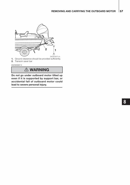
When transporting a boat on a trailer with
the outboard motor still attached, discon-
nect the fuel line from the outboard motor
beforehand and keep the outboard motor
in the normal running position or on a tran-
som saver bar.
Tiller handle typeTo prevent the outboard motor from mov-
ing when it is attached on a boat during
transport on a trailer, properly tighten the
steering friction lever (page 58).
3. Traillering
CAUTION
WARNING
ENOF01416-1
ENOF01415-0
WARNING
CAUTION
ENOF00075-1
REMOVING AND CARRYING THE OUTBOARD MOTOR 57
8
1. Ground clearance should be provided sufficiently.2. Transom saver bar
ENOW00067-0
Do not go under outboard motor tilted up
even if it is supported by support bar, or
accidental fall of outboard motor could
lead to severe personal injury.
WARNING
2 1
ENOF00073-A
58
9
ADJUSTMENT
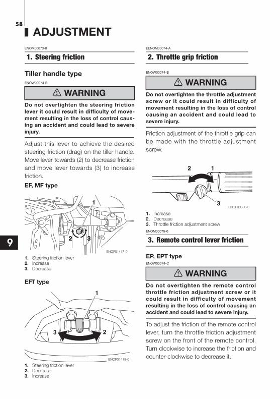
ENOM00073-0
Tiller handle typeENOW00074-B
Do not overtighten the steering friction
lever it could result in difficulty of move-
ment resulting in the loss of control caus-
ing an accident and could lead to severe
injury.
Adjust this lever to achieve the desired
steering friction (drag) on the tiller handle.
Move lever towards (2) to decrease friction
and move lever towards (3) to increase
friction.
EF, MF type
1. Steering friction lever2. Increase3. Decrease
EFT type
1. Steering friction lever2. Decrease3. Increase
EENOM00074-A
ENOW00074-B
Do not overtighten the throttle adjustment
screw or it could result in difficulty of
movement resulting in the loss of control
causing an accident and could lead to
severe injury.
Friction adjustment of the throttle grip can
be made with the throttle adjustment
screw.
1. Increase2. Decrease3. Throttle friction adjustment screw
ENOM00075-0
EP, EPT typeENOW00074-C
Do not overtighten the remote control
throttle friction adjustment screw or it
could result in difficulty of movement
resulting in the loss of control causing an
accident and could lead to severe injury.
To adjust the friction of the remote control
lever, turn the throttle friction adjustment
screw on the front of the remote control.
Turn clockwise to increase the friction and
counter-clockwise to decrease it.
1. Steering friction
WARNING
1
2 32 3
ENOF01417-0
1
23
ENOF01418-0
2. Throttle grip friction
WARNING
3. Remote control lever friction
WARNING
2 1
3ENOF00330-0
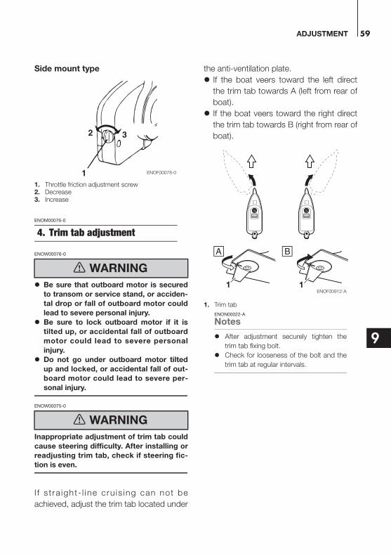
ADJUSTMENT 59
9
Side mount type
1. Throttle friction adjustment screw2. Decrease3. Increase
ENOM00076-0
ENOW00076-0
Be sure that outboard motor is secured
to transom or service stand, or acciden-
tal drop or fall of outboard motor could
lead to severe personal injury.
Be sure to lock outboard motor if it is
tilted up, or accidental fall of outboard
motor could lead to severe personal
injury.
Do not go under outboard motor tilted
up and locked, or accidental fall of out-
board motor could lead to severe per-
sonal injury.
ENOW00075-0
Inappropriate adjustment of trim tab could
cause steering difficulty. After installing or
readjusting trim tab, check if steering fic-
tion is even.
I f s t ra ight- l ine cru is ing can not be
achieved, adjust the trim tab located under
the anti-ventilation plate.
If the boat veers toward the left direct
the trim tab towards A (left from rear of
boat).
If the boat veers toward the right direct
the trim tab towards B (right from rear of
boat).
1. Trim tab
ENON00022-A
Notes
After adjustment securely tighten the
trim tab fixing bolt.
Check for looseness of the bolt and the
trim tab at regular intervals.
4. Trim tab adjustment
WARNING
WARNING
32
1 ENOF00078-0
11ENOF00912-A

60
10
INSPECTION AND MAINTENANCE
ENOM00077-0
Care of your outboard motorTo keep your outboard motor in the best
operating condition, it is very important
that you perform daily and periodic main-
tenance as suggested in the maintenance
schedules that follow.
ENOW00077-0
Your personal safety and that of your
passengers depends on how well you
maintain your outboard motor. Carefully
observe all of the inspection and mainte-
nance procedures described in this sec-
tion.
The maintenance intervals shown in the
checklist apply to an outboard motor in
normal use. If you use your outboard
motor under severe conditions such as
frequent full-throttle operation, frequent
operation in brackish water, or for com-
mercial use, maintenance should be per-
formed at shorter intervals. If in doubt,
consult your dealer for advice.
We strongly recommend that you use
only genuine replacement parts on your
outboard motor. Damage to your out-
board motor arising from the use of
other than genuine parts is not covered
under the warranty.
CAUTION
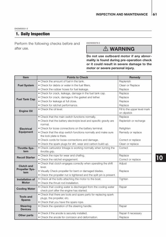
INSPECTION AND MAINTENANCE 61
10
ENOM00551-0
Perform the following checks before and
after use.
ENOW00078-0
Do not use outboard motor if any abnor-
mality is found during pre-operation check
or it could result in severe damage to the
motor or severe personal injury.
1. Daily Inspection
WARNING
Item Points to Check Remedy
Fuel System
• Check the amount of fuel in the tank. Replenish
• Check for debris or water in the fuel filters. Clean or Replace
• Check the rubber hoses for fuel leakage. Replace
Fuel Tank Cap
• Check for crack, leakage, damage in the fuel tank cap. Replace
• Check for crack, damage in the gasket and tether. Replace
• Check for leakage at full close. Replace
• Check for ratchet performance. Replace
Engine Oil• Check the oil level. Fill to the upper level mark
on dipstick
Electrical Equipment
• Check that the main switch functions normally. Replace
• Check that the battery electrolyte level and specific gravity are
normal.
Replenish or recharge
• Check for loose connections on the battery terminal. Retighten
• Check that the stop switch functions normally and make sure
the lock plate is there.
Remedy or replace
• Check cords for loose connections and damage. Correct or replace
• Check the spark plugs for dirt, wear and carbon build-up. Clean or replace
Throttle Sys-tem
• Check carburetor linkage is working normally when turning the
throttle grip.
Correct
Recoil Starter• Check the rope for wear and chafing. Replace
• Check the ratchet engagement. Correct or replace
Clutch and Propeller Sys-
tem
• Check that clutch engages correctly when operating the shift
lever.
Adjust
• Visually Check propeller for bent or damaged blades. Replace
• Check the propeller nut is tightened and the split pin is present.
Installation of Motor
• Check all the bolts attaching the motor to the boat. Tighten
• Check the thrust rod installation.
Cooling Water• Check that cooling water is discharged from the cooling water
check port after the engine has started.
Repair
Tools and Spares
• Check that there are tools and spare parts for replacing spark
plugs, the propeller, etc.
• Check that you have the spare rope.
Steering Devices
• Check the operation of the steering handle. Repair
Other parts• Check if the anode is securely installed. Repair if necessary
• Check the anode for corrosion and deformation. Replace

INSPECTION AND MAINTENANCE62
10
ENOM00081-A
Oil level checkingIf the oil level is low, or too high, the life of
the engine will be shortened significantly.
1. Stop the engine and set it in a vertical
position.
2. Remove the top cowl.
3. Remove the dipstick after 5 minutes
engine has stopped.
4. Wipe oil off the oil dipstick with a clean
rag.
5. Put in the dipstick.
6. Take out the dipstick and check the oil
level.
7. Return the dipstick.
1. Filler cap2. Dipstick
1. Upper level 800 mL2. Lower level 600 mL
ENON00024-0
Note
The oil level should be checked when the
engine is cold.
ENON00025-0
Note
Consult with an authorized dealer if the
engine oil is milky color, or appears contam-
inated.
ENOM00082-A
Engine oil replenishingENOW00079-A
Do not add engine oil of brand and grade
other than existing one. In case engine
oil of other brand or grade is added,
drain all oil and ask dealer for treatment.
In case other than engine oil such as
gasoline is put in the oil chamber, empty
the chamber and ask dealer for treat-
ment.
When replenishing engine oil, be careful
not to allow entry of foreign matters
such as dust and water into oil chamber.
Wipe off engine oil well immediately if
spilled and dispose of it in accordance
with local fire prevention and environ-
ment protection regulations.
Do not replenish engine oil over upper
limit. If overfilled, remove oil to upper
limit. If engine oil is over the upper limit,
it can leak potentially leading to engine
damage.
If the oil level is low, or at lowest mark, add
recommended oil to the middle dipstick
mark.
1
2
ENOF01419-0
2
1
ENOF00081-0
CAUTION
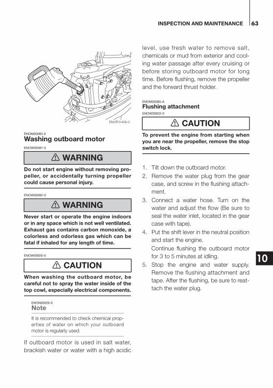
INSPECTION AND MAINTENANCE 63
10
ENOM00083-0
Washing outboard motorENOW00081-0
Do not start engine without removing pro-
peller, or accidentally turning propeller
could cause personal injury.
ENOW00082-0
Never start or operate the engine indoors
or in any space which is not well ventilated.
Exhaust gas contains carbon monoxide, a
colorless and odorless gas which can be
fatal if inhaled for any length of time.
ENOW00920-0
When washing the outboard motor, be
careful not to spray the water inside of the
top cowl, especially electrical components.
ENON00026-0
Note
It is recommended to check chemical prop-
erties of water on which your outboard
motor is regularly used.
If outboard motor is used in salt water,
brackish water or water with a high acidic
level, use fresh water to remove salt,
chemicals or mud from exterior and cool-
ing water passage after every cruising or
before storing outboard motor for long
time. Before flushing, remove the propeller
and the forward thrust holder.
ENOM00085-A
Flushing attachmentENOW00922-0
To prevent the engine from starting when
you are near the propeller, remove the stop
switch lock.
1. Tilt down the outboard motor.
2. Remove the water plug from the gear
case, and screw in the flushing attach-
ment.
3. Connect a water hose. Turn on the
water and adjust the flow (Be sure to
seal the water inlet, located in the gear
case with tape).
4. Put the shift lever in the neutral position
and start the engine.
Continue flushing the outboard motor
for 3 to 5 minutes at idling.
5. Stop the engine and water supply.
Remove the flushing attachment and
tape. After the flushing, be sure to reat-
tach the water plug.
WARNING
WARNING
CAUTION
ENOF01409-0 CAUTION

INSPECTION AND MAINTENANCE64
10
.
1. Flushing attachment (option)
ENOM00085-A
Flushing by test tankENOW00081-0
Do not start engine without removing pro-
peller, or accidentally turning propeller
could cause personal injury.
ENOW00082-0
Never start or operate the engine indoors
or in any space which is not well ventilated.
Exhaust gas contains carbon monoxide, a
colorless and odorless gas which can be
fatal if inhaled for any length of time.
ENOW00036-A
When the engine is started in the test tank,
to avoid over heating and water pump
damage, be sure the water level is at least
10 cm (4 in.) above the anti ventilation
plate.
And be sure to remove the propeller, when
starting the engine in the test tank. (See
page 71)
Run the engine only at idling.
1. Test tank2. Water3. Over 10 cm (4 in.)
ENOM00950-0
Fuse replacement (For electrical
sytarter type)ENOW00923-0
Before replacing a fuse, disconnect the
battery cable from the battery negative (-)
terminal. Failure to do so may cause a
short-circuit.
ENOW00924-0
Never use a fuse with a rating that exceeds
the specified rating as this could cause
serious damage to the electrical system.
If a blown fuse is detected, try to deter-
mine the cause for this and correct it. If the
cause for the problem is not corrected, the
fuse will likely blow again.
If the fuse continues to blow, request an
authorized Tohatsu dealer to inspect the
outboard motor.
WARNING
WARNING
CAUTION
ENOF01420-0
1
1
CAUTION
CAUTION
1
3
2
ENOF00863-0

INSPECTION AND MAINTENANCE 65
10
1. Stop the engine and disconnect the
battery cable from the battery negative
(-) terminal.
2. Remove the engine cover.
3. Remove the fuse box lid.
4. Remove the fuse and check it. If the
fuse is blown, replace it with a fuse of
the same specified rating. The out-
board motor is supplied with spare
fuses in the spare fuse holder.
1. Blown fuse
1
ENOF01421-0

INSPECTION AND MAINTENANCE66
10
ENOM00555-0
It is important to inspect and maintain your outboard motor regularly. At each interval on
the chart below, be sure to perform the indicated servicing.
Maintenance intervals should be determined according to the number of hours or number
of months, whichever comes first.
*1: Have this handled by your dealer.
2. Periodic Inspection
Description
Inspection intervals
Inspection procedure RemarksFirst 20
hours of 1
month
Every 50
hours of 3
months
Every 100
hours of 6
months
Every 200
hours of 1
year
Fuel System
Carburetor*1 Strip, Clean, and adjust.
Fuel filterCheck and clean or Replace if neces-sary.
Piping/Hoses Check and Replace if necessary.
Fuel tank Check and Replace if necessary.
Fuel tank cap Check and Replace if necessary.
Fuel pump*1Check and Replace if necessary.Disassemble and check each 300 hours.
IgnitionSpark plug
Check gaps.Remove carbon deposits or Replace.
0.8–0.9 mm (0.031–0.035 in)
Ignition timing*1 Check timing.
Starting Sys-tem
Starter rope Check for wear or chafing
Starter Motor*1Check for salt deposits and the battery cable condition.
Battery Check installation, fluid quantity, gravity.
Engine
Engine oilReplace Replace Replace
Replace if necessary.
Valve Clearance*1 Check & adjust.
IN:0.13–0.17 mm (0.0051–0.0067 in)EX:0.18–0.22 mm (0.0071–0.0087 in)
Timing Belt*1 Check and Replace if necessary.
Thermostat*1 Check and Replace if necessary.
Lower Unit
Propeller Check for bent blades, damage, wear.
Gear oilReplace Replace Replace Change or replenish-oil and check for
water leaks.320 mL(10.8 fl.oz.)
Water pump*1 Check for wear or damage.Replace impeller every 12 months.
Bolts and Nuts Retighten
Sliding and Rotating Parts. Grease Nipples
Apply and pump in grease.
Outer Equipment Check for corrosion.
Anode Check for corrosion and deformation.Replace if neces-sary.

INSPECTION AND MAINTENANCE 67
10
ENON00030-0
Note
Your outboard motor should receive careful, and complete inspection at 300 hours. This is the best
time for major maintenance procedures to be carried out.
ENOM00091-A
Engine oil replacementENOW00091-0
You may be injured due to high engine
temperatures if you fill engine oil just after
stopping. Changing engine oil should be
done after the engine has been cooled.
ENOW00092-A
Do not overfill engine oil, or engine oil
could leak and/or engine could be dam-
aged. If engine oil level is over upper
limit marks of oil gauge, drain oil to level
lower than upper limit.
Be sure that outboard motor is in upright
and level position when checking or
changing oil.
Stop engine immediately if low oil pres-
sure warning lamp is lit or oil leak is
found, or engine could be severely dam-
aged. Consult dealer.
Wipe off engine oil well immediately if
spilled and dispose of it in accordance
with local fire prevention and environ-
ment protection regulations.
ENOW00090-0
Use of engine oils that do not meet these
requirements will result in reduced engine
life, and other engine problems.
ENOW00933-0
Engine oil mixed with dust or water will
dramatically shorten the life of the engine.
To change engine oil:
Be sure to use recommended engine oil
(see page 13).
1. Stop the engine and allow it to cool.
2. Tilt up the outboard motor and lock the
tilt with the tilt stopper.
3. Turn the steering on the outboard
motor so that the drain hole is facing
downward.
4. Put a oil drain pan under the oil drain
screw.
5. Remove the oil drain screw and com-
pletely drain oil from the engine.
1. Drain hole
6. Tighten the oil drain screw with apply-
ing oil on the sealing surface of screw.
(Use new oil drain washer)
Oil drain screw specified torque
24N·m (17 ft·lb, 2.4 kgf·m)
CAUTION
CAUTION
CAUTION
CAUTION
1
ENOF01422-1
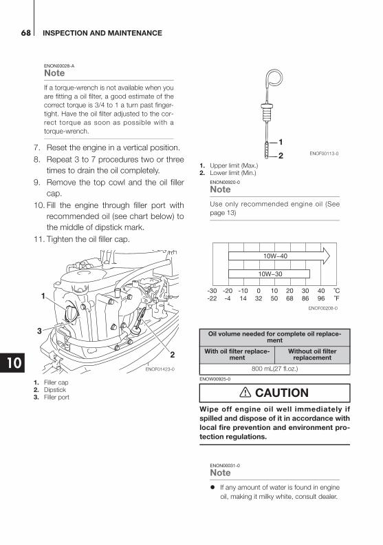
INSPECTION AND MAINTENANCE68
10
ENON00028-A
Note
If a torque-wrench is not available when you
are fitting a oil filter, a good estimate of the
correct torque is 3/4 to 1 a turn past finger-
tight. Have the oil filter adjusted to the cor-
rect torque as soon as possible with a
torque-wrench.
7. Reset the engine in a vertical position.
8. Repeat 3 to 7 procedures two or three
times to drain the oil completely.
9. Remove the top cowl and the oil filler
cap.
10. Fill the engine through filler port with
recommended oil (see chart below) to
the middle of dipstick mark.
11. Tighten the oil filler cap.
1. Filler cap2. Dipstick3. Filler port
1. Upper limit (Max.)2. Lower limit (Min.)
ENON00920-0
Note
Use only recommended engine oil (See
page 13)
ENOW00925-0
Wipe off engine oil well immediately if
spilled and dispose of it in accordance with
local fire prevention and environment pro-
tection regulations.
ENON00031-0
Note
If any amount of water is found in engine
oil, making it milky white, consult dealer.
1
2
3
ENOF01423-0
Oil volume needed for complete oil replace-ment
With oil filter replace-ment
Without oil filter replacement
800 mL(27 fl.oz.)
CAUTION
2
1
ENOF00113-0
10W−40
10W−30
˚C˚F
4096
3086
2068
1050
032
-1014
-20-4
-30-22
ENOF00208-0

INSPECTION AND MAINTENANCE 69
10
If engine oil is contaminated with fuel,
emitting strong fuel smell, consult dealer.
Some oil dilution is normal if engine is
idled or trolled for long periods, espe-
cially in cooler water temperatures.
ENOM00093-A
Fuel filters and fuel tank cleaningENOW00093-A
Gasoline and its vapors are very flammable
and can be explosive.
Do not start this procedure while engine
is operating or hot even after stopping it.
Place fuel filter away from every source
of ignition such as sparks or open
flames.
Wipe off gasoline well immediately if
spilled and dispose of it in accordance
with local fire prevention and environ-
ment protection regulations.
Install fuel filter with all related parts in
place, or fuel leak could occur, leading
to catching fire or explosion.
Check fuel system regularly for leakage.
Contact authorized dealer for fuel sys-
tem services. Services by unqualified
person could lead to engine damage.
Fuel filters are provided inside the fuel tank
and engine.
ENOM00094-0
Fuel filter (for engine)1. Replace the fuel filter provided inside of
engine cover if there is water or dirt
inside.
1. Fuel filter
WARNING1
ENOF00560-0
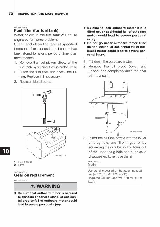
INSPECTION AND MAINTENANCE70
10
ENOM00096-A
Fuel filter (for fuel tank)Water or dirt in the fuel tank will cause
engine performance problems.
Check and clean the tank at specified
times or after the outboard motor has
been stored for a long period of time (over
three months).
1. Remove the fuel pickup elbow of the
fuel tank by turning it counterclockwise
2. Clean the fuel filter and check the O-
ring. Replace it if necessary.
3. Reassemble all parts.
1. Fuel pick up2. Filter
ENOM00098-A
Gear oil replacementENOW00094-0
Be sure that outboard motor is secured
to transom or service stand, or acciden-
tal drop or fall of outboard motor could
lead to severe personal injury.
Be sure to lock outboard motor if it is
tilted up, or accidental fall of outboard
motor could lead to severe personal
injury.
Do not go under outboard motor tilted
up and locked, or accidental fall of out-
board motor could lead to severe per-
sonal injury.
1. Tilt down the outboard motor.
2. Remove the oil plugs (lower and
upper), and completely drain the gear
oil into a pan.
3. Insert the oil tube nozzle into the lower
oil plug hole, and fill with gear oil by
squeezing the oil tube until oil flows out
of the upper plug hole and bubbles is
disappeared to remove the air.
ENON00033-0
Note
Use genuine gear oil or the recommended
one (API GL-5: SAE #80 to #90).
Required volume: approx. 320 mL (10.8
fl.oz.).
WARNING
1
2
ENOF01226-0
ENOF01424-0
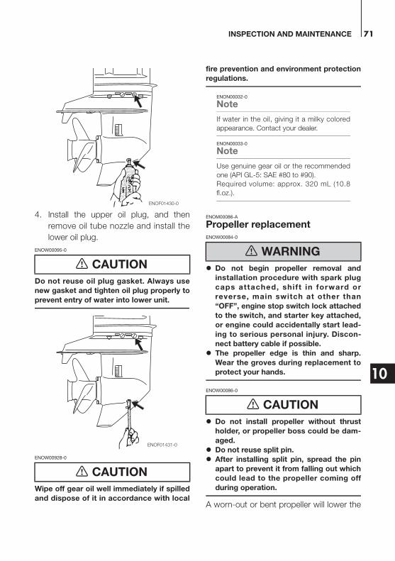
INSPECTION AND MAINTENANCE 71
10
4. Install the upper oil plug, and then
remove oil tube nozzle and install the
lower oil plug.
ENOW00095-0
Do not reuse oil plug gasket. Always use
new gasket and tighten oil plug properly to
prevent entry of water into lower unit.
ENOW00928-0
Wipe off gear oil well immediately if spilled
and dispose of it in accordance with local
fire prevention and environment protection
regulations.
ENON00032-0
Note
If water in the oil, giving it a milky colored
appearance. Contact your dealer.
ENON00033-0
Note
Use genuine gear oil or the recommended
one (API GL-5: SAE #80 to #90).
Required volume: approx. 320 mL (10.8
fl.oz.).
ENOM00086-A
Propeller replacementENOW00084-0
Do not begin propeller removal and
installation procedure with spark plug
caps attached, shift in forward or
reverse, main switch at other than
“OFF”, engine stop switch lock attached
to the switch, and starter key attached,
or engine could accidentally start lead-
ing to serious personal injury. Discon-
nect battery cable if possible.
The propeller edge is thin and sharp.
Wear the groves during replacement to
protect your hands.
ENOW00086-0
Do not install propeller without thrust
holder, or propeller boss could be dam-
aged.
Do not reuse split pin.
After installing split pin, spread the pin
apart to prevent it from falling out which
could lead to the propeller coming off
during operation.
A worn-out or bent propeller will lower the
CAUTION
CAUTION
ENOF01430-0
ENOF01431-0
WARNING
CAUTION

INSPECTION AND MAINTENANCE72
10
motor's performance, and cause engine
trouble.
1. Put a piece of wood block between
propeller blade and anti-ventilation
plate to hold propeller.
2. Remove the split pin, propeller nut and
washer.
3. Remove the propeller and thrust
holder.
4. Apply water proof grease to the pro-
peller shaft before installing a new pro-
peller.
5. Install the thrust holder, propeller,
stopper, washer and propeller nut onto
the shaft.
1. Propeller2. Thrust holder3. Washer4. Propeller nut5. Split pin
6. Tighten the propeller nut to specified
torque, and align one of grooves to
propeller shaft hole.
Propeller nut torque:
12 N·m (9 ft·lb, 1.2kgf·m)
7. Install a new split pin into the nut hole
and bend it.
ENOM00087-A
Spark plugs replacementENOW00087-0
Do not reuse spark plug with damaged
insulation, or sparks can leak through
crack, potentially leading to electric
shock, explosion and/or fire.
Do not touch spark plugs immediately
after stopping engine as they will be hot
and cou ld cause severe bur ns i f
touched. Allow motor to cool down first.
ENOW00929-0
Use only the recommended spark plugs.
Spark plugs which have an different heat
range may cause engine damage.
If the spark plug(s) is fouled, has carbon
build up, or is worn, it should be replaced.
When reusing spark plugs, remove dirt
from the electrodes and adjust spark gap
to specification.
1. Stop the engine.
ENOF00084-B
12 3
5
4
ENOF01432-0
WARNING
CAUTION
ENOF00084-D

INSPECTION AND MAINTENANCE 73
10
2. Remove the top cowl.
3. Remove the spark plug caps.
4. Remove the spark plugs by turning it
counter-clockwise, using a 5/8" (16
mm) socket wrench and handle that is
provided in tool bag.
5. Inspect the spark plug. Replace the
spark plug if the electrodes are worn or
i f the insu la to rs a re c racked or
chipped.
6. Measure the spark plug electrode gap
with a wire type feeler gauge. The gap
should be 0.8-0.9 mm (0.031-0.035
inches). If the gap is different, replace
the spark plug with a new one
Use spark plug NGK DCPR-6E.
1. Electrode2. Spark gap (0.8–0.9 mm, 0.031–0.035 in)
7. Install the spark plug by hand and turn
it carefully to avoid cross-threading.
8. Tighten the spark plug to the specified
torque.
ENON00028-0
Note
Spark plug torque:
18.0 N·m (13.3 ft·lb) [1.84 kgf·m]
If a torque-wrench is not available when you
are fitting a spark plug, a good estimate of
the correct torque is 1/4 to 1/2 a turn past
finger-tight. Have the spark plug adjusted to
the correct torque as soon as possible with
a torque-wrench.
12
ENOF00085-0
ENOF01427-0

INSPECTION AND MAINTENANCE74
10
ENOM00088-A
Anode replacementA sacrificial anode protects the outboard motor from electrolytic corrosion. Anode is
located on the gear case, cylinder etc.. When the anode is eroded more than 1/3 of origi-
nal size, replace it.
ENON00029-0
Notes
Never grease or paint the anode.
At each inspection re-tighten the anode attaching bolt. As it is likely to be subjected to electrolytic
corrosion.
*1 : Only for Power tilt model*2 : Remove CD unit to access the anode.
ENOF01428-0
*1
*2
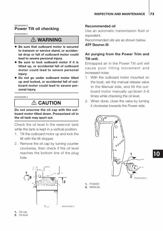
INSPECTION AND MAINTENANCE 75
10
ENOM00089-B
Power Tilt oil checkingENOW00088-0
Be sure that outboard motor is secured
to transom or service stand, or acciden-
tal drop or fall of outboard motor could
lead to severe personal injury.
Be sure to lock outboard motor if it is
tilted up, or accidental fall of outboard
motor could lead to severe personal
injury.
Do not go under outboard motor tilted
up and locked, or accidental fall of out-
board motor could lead to severe per-
sonal injury.
ENOW00089-A
Do not unscrew the oil cap with the out-
board motor tilted down. Pressurized oil in
the oil tank may spurt out.
Check the oil level in the reservoir tank
while the tank is kept in a vertical position.
1. Tilt the outboard motor up and lock the
tilt with the tilt stopper.
2. Remove the oil cap by turning counter
clockwise, then check if the oil level
reaches the bottom line of the plug
hole.
1. Oil cap2. Oil level
Recommended oil
Use an automatic transmission fluid or
equivalent.
Recommended oils are as shown below.
ATF Dexron III
Air purging from the Power Trim and
Tilt unit.
Entrapped air in the Power Tilt unit will
cause poor t i l t i ng movement and
increased noise.
1. With the outboard motor mounted on
the boat, set the manual release valve
to the Manual side, and tilt the out-
board motor manually up/down 5-6
times while checking the oil level.
2. When done, close the valve by turning
it clockwise towards the Power side.
1. POWER2. MANUAL
WARNING
CAUTION
1
2
ENOF00558-0
1
2ENOF00326-0
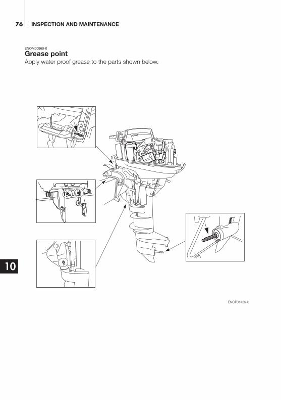
INSPECTION AND MAINTENANCE76
10
ENOM00960-0
Grease pointApply water proof grease to the parts shown below.
ENOF01429-0
INSPECTION AND MAINTENANCE 77
10
ENOM00100-A
ENOW00934-0
Be sure to disconnect fuel connector
except when operating engine.
Fuel leakage is a fire or explosion haz-
ard, which can cause serious injury or
death.
ENOW00097-0
Be sure to use cloth to remove fuel remain-
ing in the cowl and dispose of it in accor-
dance with local f ire prevention and
environment protection regulations.
ENOW00096-0
Before servicing the motor for storage:
Remove the battery cables.
Remove the spark plug caps from the
spark plugs.
Do not run the motor out of the water.
Before you put your outboard motor in
storage, it is a good opportunity to have it
serviced and prepared by your dealer.
Be sure to use fuel stabilizer while running
the motor before storage. (See page 78)
ENOM00101-A
Engine1. Wash the engine exterior and flush the
cooling water system thoroughly with
fresh water. Drain the water com-
pletely.
Wipe off any surface water with an oily
rag.
2. Remove the fuel hose from the out-
board motor.
3. Drain all fuel from the fuel hoses, fuel
pump and carburetor (See page 79),
and clean these parts.
Keep in mind that if gasoline is kept in
the carburetor for a long time, gum
and varnish will develop, causing the
float valve to stick, restricting the fuel
flow.
4. Remove the spark plugs and put a tea-
spoon of engine oil or spray storage oil
into the combustion chamber through
the spark plug holes.
5. Turn the starter motor several turns to
lubricate inside the cylinder.
ENOW00930-0
Be sure to remove stop switch lock to
prevent ignited the spark plugs.
Put a cloth to spark plug hole and wipe
up any spilled engine oil, when cranking
the outboard motor.
6. Change the engine oil (See page 67).
7. Change the gear oil in the gear case
(See page 70).
8. Apply grease to grease point (See
page 76).
3. Off-season storage
WARNING
WARNING
CAUTION WARNING

INSPECTION AND MAINTENANCE78
10
9. Stand the outboard motor up vertically
in a dry place.
ENOW00066-0
Do not carry or store outboard motor in
any of positions described below.
Otherwise, engine damage or property
damage could result from leaking oil.
ENON00021-A
Note
If the outboard motor must be laid down
be sure drain the fuel and engine oil,
then the outboard motor on a cushion
as shown in the drawing below (See
page 77 and 55).
Elevate power unit 2 inches to 4 inches if
traveling to avoid oil spillage.
ENOM00950-0
Adding a fuel stabilizerWhen adding a fuel stabilizer additive
(commercially available), first fill the fuel
tank with fresh fuel. If the fuel tank is only
partially filled, air in the tank can cause the
fuel to deteriorate during storage.
1. Before adding fuel stabilizer additive,
drain the carburetor (See page 79).
2. Follow the instructions on the label
when adding the fuel stabilizer additive.
3. After adding the additive, let the out-
board motor run in the water for 10
minutes to make sure any old fuel in
the fuel system has been completely
replaced by the fuel with additive.
4. Turn the engine OFF
ENON00891-0
Note
If your motor is used occasionally, it is rec-
ommended to use a good fuel stabilizer in
every tank of fuel and keep the container full
to reduce condensation and evaporation.
CAUTION
ENOF01416-1
ENOF01414-1
ENOF01415-0
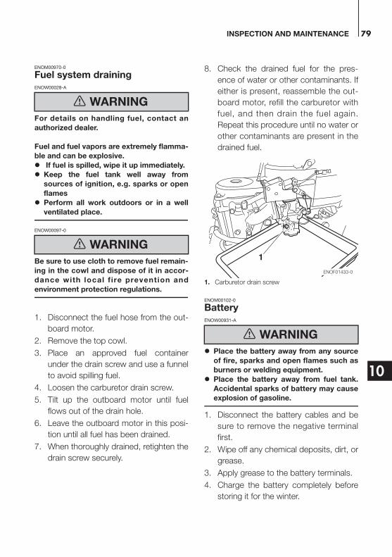
INSPECTION AND MAINTENANCE 79
10
ENOM00970-0
Fuel system drainingENOW00028-A
For details on handling fuel, contact an
authorized dealer.
Fuel and fuel vapors are extremely flamma-
ble and can be explosive.
If fuel is spilled, wipe it up immediately.
Keep the fuel tank well away from
sources of ignition, e.g. sparks or open
flames
Perform all work outdoors or in a well
ventilated place.
ENOW00097-0
Be sure to use cloth to remove fuel remain-
ing in the cowl and dispose of it in accor-
dance with local f ire prevention and
environment protection regulations.
1. Disconnect the fuel hose from the out-
board motor.
2. Remove the top cowl.
3. Place an approved fuel container
under the drain screw and use a funnel
to avoid spilling fuel.
4. Loosen the carburetor drain screw.
5. Tilt up the outboard motor until fuel
flows out of the drain hole.
6. Leave the outboard motor in this posi-
tion until all fuel has been drained.
7. When thoroughly drained, retighten the
drain screw securely.
8. Check the drained fuel for the pres-
ence of water or other contaminants. If
either is present, reassemble the out-
board motor, refill the carburetor with
fuel, and then drain the fuel again.
Repeat this procedure until no water or
other contaminants are present in the
drained fuel.
1. Carburetor drain screw
ENOM00102-0
BatteryENOW00931-A
Place the battery away from any source
of fire, sparks and open flames such as
burners or welding equipment.
Place the battery away from fuel tank.
Accidental sparks of battery may cause
explosion of gasoline.
1. Disconnect the battery cables and be
sure to remove the negative terminal
first.
2. Wipe off any chemical deposits, dirt, or
grease.
3. Apply grease to the battery terminals.
4. Charge the battery completely before
storing it for the winter.
WARNING
WARNING
WARNING
1
ENOF01433-0

INSPECTION AND MAINTENANCE80
10
5. Recharge the battery once a month to
prevent it from discharging and the
electrolyte from deteriorating.
6. Store the battery in a dry place.
ENOM00104-A
The following steps must be taken when
first using the engine after off-season stor-
age.
1. Check that the shift and throttle func-
tion properly. (Be sure to turn the pro-
peller shaft when checking the shift
function or else the shift linkage may
be damaged.)
2. Check the electrolyte level, and mea-
sure the voltage and specific gravity of
the battery.
3. Check that the battery is secure and
the bat te ry cab les a re proper l y
installed.
4. Change the engine oil (See page 67).
5. Before starting the engine, disconnect
stop switch lock and crank approxi-
mately 10 times in order to prime the
oil pump.
6. Fill fuel tank completely.
7. Start the engine and warm up the
engine for 3 minutes in the “NEUTRAL”
position.
8. Run the engine for 5 minutes at the
slowest speed.
9. Run the engine for 10 minutes at half
throttle. The oil used for storage inside
the engine will be circulated out to
assure optimum performance.
ENOM00105-A
ENOW00098-0
Do not attempt to start submerged out-
board motor immediately after it is recov-
ered, or eng ine cou ld be severe ly
damaged.
After taking your outboard motor out of the
water, immediately take it to your dealer.
The following are the emergency measures
to be taken for a submerged outboard
motor, if you can not take it your dealer
right away.
1. Wash the outboard motor with fresh
water to remove salt or dirt.
2. Remove the engine oil drain screw and
completely drain water and oil from the
engine.
3. Remove the spark plugs, and com-
pletely drain the water from the engine
by pulling recoil starter several times.
Replace oil filter and oil to the correct
level.
The oi l and f i l ter may need to be
changed again after running a short
period to get all moisture completely
out of the crankcase.
4. Inject a sufficient amount of engine oil
through the spark plug holes.
Pull the recoil starter rope several times
to circulate the oil throughout the out-
board motor.
4. Pre-season check
Specific Gravity at 20°C
Terminal Voltage (V)
Charge Condition
1.120 10.5 Fully discharged
1.160 11.1 1/4 charged
1.210 11.7 1/2 charged
1.250 12 3/4 charged
1.280 13.2 Fully charged
5. Submerged outboard motor
CAUTION
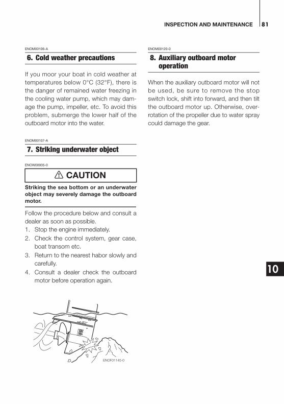
INSPECTION AND MAINTENANCE 81
10
ENOM00106-A
If you moor your boat in cold weather at
temperatures below 0°C (32°F), there is
the danger of remained water freezing in
the cooling water pump, which may dam-
age the pump, impeller, etc. To avoid this
problem, submerge the lower half of the
outboard motor into the water.
ENOM00107-A
ENOW00935-0
Striking the sea bottom or an underwater
object may severely damage the outboard
motor.
Follow the procedure below and consult a
dealer as soon as possible.
1. Stop the engine immediately.
2. Check the control system, gear case,
boat transom etc.
3. Return to the nearest habor slowly and
carefully.
4. Consult a dealer check the outboard
motor before operation again.
ENOM00120-0
When the auxiliary outboard motor will not
be used, be sure to remove the stop
switch lock, shift into forward, and then tilt
the outboard motor up. Otherwise, over-
rotation of the propeller due to water spray
could damage the gear.
6. Cold weather precautions
7. Striking underwater object
CAUTION
ENOF01145-0
8. Auxiliary outboard motor operation
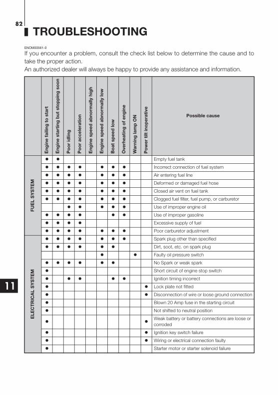
82
11
TROUBLESHOOTING
ENOM00561-0
If you encounter a problem, consult the check list below to determine the cause and to
take the proper action.
An authorized dealer will always be happy to provide any assistance and information.
En
gin
e f
ailin
g t
o s
tart
En
gin
e s
tart
ing
bu
t sto
pp
ing
so
on
Po
or
idlin
g
Po
or
ac
ce
lera
tio
n
En
gin
e s
pe
ed
ab
no
rma
lly h
igh
En
gin
e s
pe
ed
ab
no
rma
lly lo
w
Bo
at
sp
ee
d lo
w
Ove
rhe
ati
ng
of
en
gin
e
Wa
rnin
g la
mp
ON
Po
we
r ti
lt in
op
era
tive
Possible cause
FU
EL
SY
ST
EM
Empty fuel tank
Incorrect connection of fuel system
Air entering fuel line
Deformed or damaged fuel hose
Closed air vent on fuel tank
Clogged fuel filter, fuel pump, or carburetor
Use of improper engine oil
Use of improper gasoline
Excessive supply of fuel
Poor carburetor adjustment
EL
EC
TR
ICA
L S
YS
TE
M
Spark plug other than specified
Dirt, soot, etc. on spark plug
Faulty oil pressure switch
No Spark or weak spark
Short circuit of engine stop switch
Ignition timing incorrect
Lock plate not fitted
Disconnection of wire or loose ground connection
Blown 20 Amp fuse in the starting circuit
Not shifted to neutral position
Weak battery or battery connections are loose or
corroded
Ignition key switch failure
Wiring or electrical connection faulty
Starter motor or starter solenoid failure
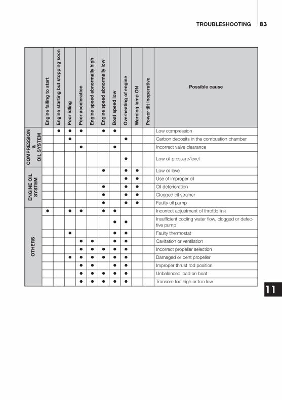
TROUBLESHOOTING 83
11
CO
MP
RE
SS
ION
&O
IL S
YS
TE
M
Low compression
Carbon deposits in the combustion chamber
Incorrect valve clearance
Low oil pressure/level
EN
GIN
E O
ILS
YS
TE
M
Low oil level
Use of improper oil
Oil deterioration
Clogged oil strainer
Faulty oil pump
OT
HE
RS
Incorrect adjustment of throttle link
Insufficient cooling water flow, clogged or defec-
tive pump
Faulty thermostat
Cavitation or ventilation
Incorrect propeller selection
Damaged or bent propeller
Improper thrust rod position
Unbalanced load on boat
Transom too high or too low
En
gin
e f
ailin
g t
o s
tart
En
gin
e s
tart
ing
bu
t sto
pp
ing
so
on
Po
or
idlin
g
Po
or
ac
ce
lera
tio
n
En
gin
e s
pe
ed
ab
no
rma
lly h
igh
En
gin
e s
pe
ed
ab
no
rma
lly lo
w
Bo
at
sp
ee
d lo
w
Ove
rhe
ati
ng
of
en
gin
e
Wa
rnin
g la
mp
ON
Po
we
r ti
lt in
op
era
tive
Possible cause
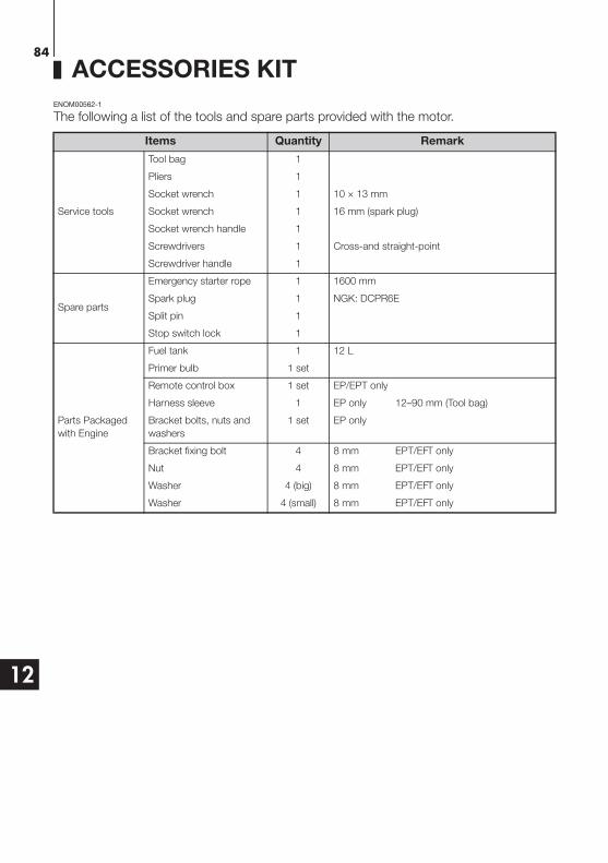
84
12
ACCESSORIES KIT
ENOM00562-1
The following a list of the tools and spare parts provided with the motor.
Items Quantity Remark
Service tools
Tool bag 1
Pliers 1
Socket wrench 1 10 × 13 mm
Socket wrench 1 16 mm (spark plug)
Socket wrench handle 1
Screwdrivers 1 Cross-and straight-point
Screwdriver handle 1
Spare parts
Emergency starter rope 1 1600 mm
Spark plug 1 NGK: DCPR6E
Split pin 1
Stop switch lock 1
Parts Packaged
with Engine
Fuel tank 1 12 L
Primer bulb 1 set
Remote control box 1 set EP/EPT only
Harness sleeve 1 EP only 12–90 mm (Tool bag)
Bracket bolts, nuts and
washers
1 set EP only
Bracket fixing bolt 4 8 mm EPT/EFT only
Nut 4 8 mm EPT/EFT only
Washer 4 (big) 8 mm EPT/EFT only
Washer 4 (small) 8 mm EPT/EFT only
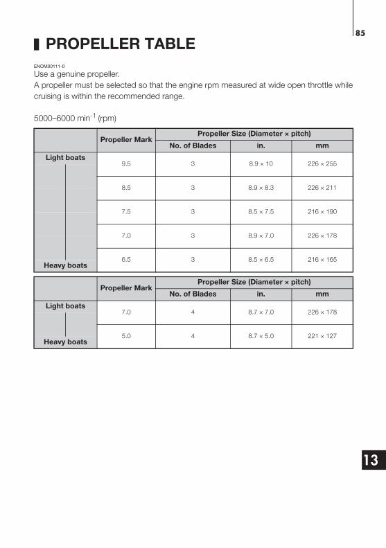
85
13
PROPELLER TABLE
ENOM00111-0
Use a genuine propeller.
A propeller must be selected so that the engine rpm measured at wide open throttle while
cruising is within the recommended range.
5000–6000 min-1 (rpm)
Propeller MarkPropeller Size (Diameter × pitch)
No. of Blades in. mm
Light boats9.5 3 8.9 × 10 226 × 255
8.5 3 8.9 × 8.3 226 × 211
7.5 3 8.5 × 7.5 216 × 190
7.0 3 8.9 × 7.0 226 × 178
6.5 3 8.5 × 6.5 216 × 165Heavy boats
Propeller MarkPropeller Size (Diameter × pitch)
No. of Blades in. mm
Light boats7.0 4 8.7 × 7.0 226 × 178
5.0 4 8.7 × 5.0 221 × 127Heavy boats

003-11113-2AF1 1604NB
Printed in Japan
MFS 6BZMFS 8B
MFS 9.8B
OWNER’S MANUAL