
USER Manual
AR25

2
Table of Contents accumet®
R E S E A R C H
Connectors
Attaching pH and ISE electrodes
Touch Screen Operation
Choosing a Channel
Button Functions
System Setup
pH Setup
mV Setup
Ion Setup
Standardization
Measurement
Absolute mV Measurement
Relative mV Measurement
4
5
6
8
10
12
14
16
18
44
80
88
102
104
108
110
111
111
Introduction
Unpacking the Meter
Specifications
Getting Started
Using the Meter
Setup Operations
pH Operations
mV Operations
3
Table of Contentsaccumet®
R E S E A R C H
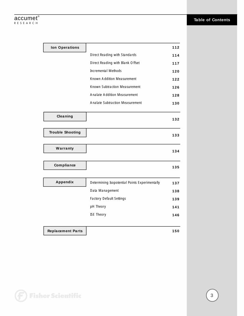
Direct Reading with Standards
Direct Reading with Blank Offset
Incremental Methods
Known Addition Measurement
Known Subtraction Measurement
Analate Addition Measurement
Analate Subtraction Measurement
Determining Isopotential Points Experimentally
Data Management
Factory Default Settings
pH Theory
ISE Theory
112
114
117
120
122
126
128
130
132
133
134
135
137
138
139
141
146
150
Ion Operations
Cleaning
Trouble Shooting
Warranty
Compliance
Appendix
Replacement Parts
4
Introduction accumet®
R E S E A R C H
Thank you for selecting a Fisher Scientific accumet pH meter. This manual describes the operation of the accumet AR25 meter. The state-of-the-art meter that you have purchased is easy to operate and will guide you through the various functions by displaying easy to understand prompts. This operating manual should answer any questions that might arise in operating your meter; however, do not hesitate to call our Fisher Lab Equipment Technical Support Hotline at 1-800/943-2006 or 412/490-6260, if you need any assistance.
This meter is designed to provide all the information necessary to guideyou through the process of measuring pH, mV, or ion concentration witha series of prompts on the screen.
The accumet Research AR25 provides microprocessor precision in a compact benchtop design that is easy to use. One touch screen controlsall procedures, letting you:
• Measure pH, absolute mV, relative mV, ion concentration • Select one of three sets of standard buffer groups.• Implement automatic buffer recognition.• Standardize with up to five standard or custom buffers.• Customize your display screen and operating parameters.• Assign operator and sample identification numbers.• Specify ion selective electrode type.• Store 250 data points in the meter’s memory or transfer data
to a computer or printer.• Access extensive online help with just a touch of a button.
It all adds up to rapid, completely automatic, intuitive operation.

5
Unpacking the Meteraccumet®
R E S E A R C H
The following is a listing of what you should have received with your newaccumet AR25 pH/mV/Ion/meter.
Meter with kit includesmeter power supplyelectrode arm support bracketelectrode armelectrode (13-620-285)ATC probe (13-620-19)manual and literature
Meter only includesmeterpower supplyelectrode arm support bracketmanual and literature
If any of these items are missing, please contact the Fisher Products Group Electrochemistry Operation by dialing 412/490-6267.
Ion Selective Electrodes are available and can be ordered by calling Fisher Customer Service at 800/766-7000.
6
Specifications accumet®
R E S E A R C H
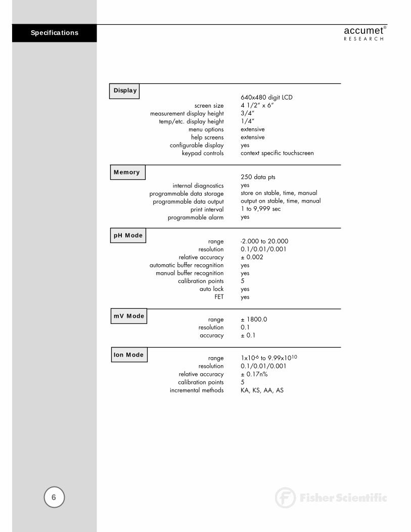
640x480 digit LCD4 1/2” x 6”3/4” 1/4” extensiveextensiveyescontext specific touchscreen
250 data ptsyesstore on stable, time, manualoutput on stable, time, manual1 to 9,999 secyes
-2.000 to 20.0000.1/0.01/0.001± 0.002yesyes5yesyes
± 1800.00.1± 0.1
1x10⁻⁶ to 9.99x10¹⁰
0.1/0.01/0.001± 0.17n%5KA, KS, AA, AS
screen sizemeasurement display height
temp/etc. display heightmenu optionshelp screens
configurable displaykeypad controls
internal diagnosticsprogrammable data storageprogrammable data output
print intervalprogrammable alarm
rangeresolution
relative accuracyautomatic buffer recognition
manual buffer recognitioncalibration points
auto lockFET
rangeresolutionaccuracy
rangeresolution
relative accuracycalibration points
incremental methods
Display
Memory
pH Mode
mV Mode
Ion Mode

7
Specificationsaccumet®
R E S E A R C H
-5.0 to +105.0 °C0.1 °C± 0.2 °C
2BNC, 2Pin, 2ATCRS232, DIN (for FET)115 V/60 Hz, 230 V/50 Hz 12VDC, 500mA± 10%>1012 ohms5.5” x 7.5” x 3.25”1.86 lb.
5-45 °C5-80 % noncondensing2000mII2
rangeresolutionaccuracy
inputs/outputs
electrical requirementsoutput from PSU
line voltage toleranceinput impedance
meter sizemeter weight
operating temperatureoperation humidity
maximum operating altitudeinstallation category
Pollution category degree
Temperature Mode
General
Operating Conditions

8
Getting Started accumet®
R E S E A R C HCONNECTORS
POWER RS-232 FET ATC 1 Ref 1 Input 1
AccuFET pH electrode
Automatic Temperature Compensation (ATC)
BNC input connector
Reference pin jack
Review the layout and arrangement of the rear connector panel.1
ACT 2 Ref 2 Input 2
Power
Computer/Printer

9
Getting Startedaccumet®
R E S E A R C HCONNECTORS
To connect RS-232, see
Data Management on
page 138.
Connect the electrode arm to the base.2
Connect the power cable to the
rear connector panel power
jack and to a power source.
3
electrode arm support
POWER
10
Getting Started accumet®
R E S E A R C HpH and ION SPECIFIC ELECTRODES
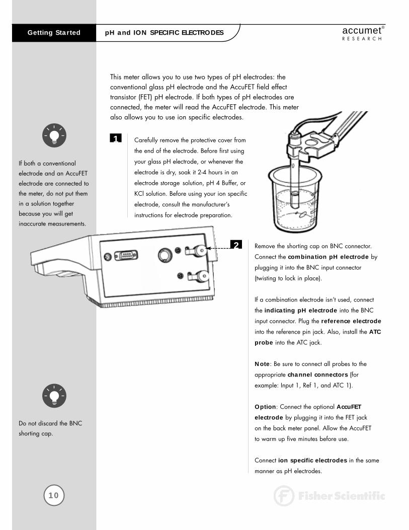
If both a conventional
electrode and an AccuFET
electrode are connected to
the meter, do not put them
in a solution together
because you will get
inaccurate measurements.
Do not discard the BNC
shorting cap.
This meter allows you to use two types of pH electrodes: the conventional glass pH electrode and the AccuFET field effect transistor (FET) pH electrode. If both types of pH electrodes areconnected, the meter will read the AccuFET electrode. This meteralso allows you to use ion specific electrodes.
Carefully remove the protective cover from
the end of the electrode. Before first using
your glass pH electrode, or whenever the
electrode is dry, soak it 2-4 hours in an
electrode storage solution, pH 4 Buffer, or
KCl solution. Before using your ion specific
electrode, consult the manufacturer’s
instructions for electrode preparation.
Remove the shorting cap on BNC connector.
Connect the combination pH electrode by
plugging it into the BNC input connector
(twisting to lock in place).
If a combination electrode isn’t used, connect
the indicating pH electrode into the BNC
input connector. Plug the reference electrode
into the reference pin jack. Also, install the ATC
probe into the ATC jack.
Note: Be sure to connect all probes to the
appropriate channel connectors (for
example: Input 1, Ref 1, and ATC 1).
Option: Connect the optional AccuFET
electrode by plugging it into the FET jack
on the back meter panel. Allow the AccuFET
to warm up five minutes before use.
Connect ion specific electrodes in the same
manner as pH electrodes.
2
1
11
Getting Startedaccumet®
R E S E A R C HpH and ION SPECIFIC ELECTRODES
Proper electrode care is
fundamental to obtaining
reliable pH measurements.
Improper care of the
electrode may cause the
meter reading to drift,
respond slowly, or
produce erroneous
readings. For this reason,
the electrode should
always be conditioned
and used in accordance
with manufacturer’s
instructions.
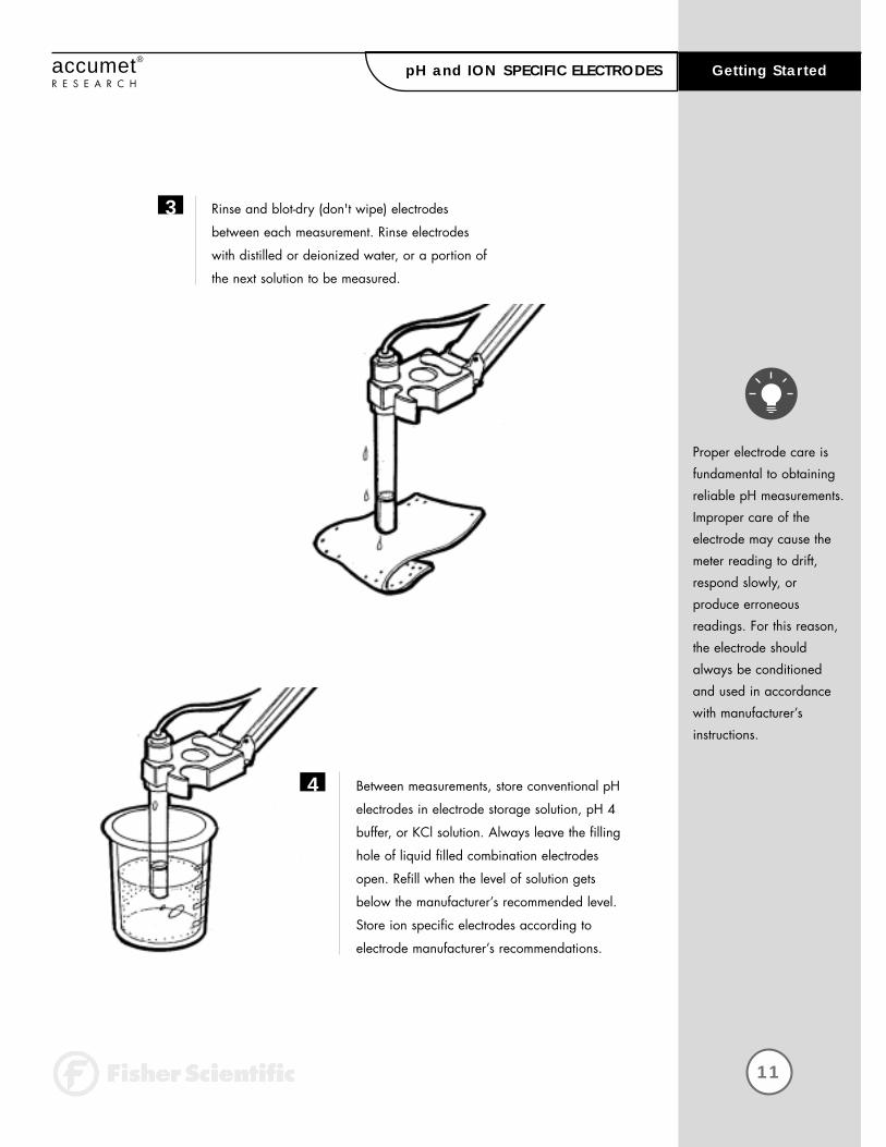
Rinse and blot-dry (don't wipe) electrodes
between each measurement. Rinse electrodes
with distilled or deionized water, or a portion of
the next solution to be measured.
Between measurements, store conventional pH
electrodes in electrode storage solution, pH 4
buffer, or KCl solution. Always leave the filling
hole of liquid filled combination electrodes
open. Refill when the level of solution gets
below the manufacturer’s recommended level.
Store ion specific electrodes according to
electrode manufacturer’s recommendations.
3
4

12
Using the Meter accumet®
R E S E A R C HTOUCH SCREEN OPERATION
Touch anywhere to resume
11:11am
FisherScientific
Standby screen

13
Using the Meteraccumet®
R E S E A R C HTOUCH SCREEN OPERATION
The new accumet Research benchtop pH meters operate with a state-of-the-art touch screen. The touch screen makes this the easiestmeter on the market to operate and care for. When the meter is firstplugged in, the STANDBY screen will appear. Touch anywhere on thisscreen to access the functions of the meter.
The buttons on the right side of the screen control all of the functions ofthe meter. A light touch on the screen is all that you need to access thevarious functions. Once you touch a button you will get an audible tone;the screen will not change until you lift your finger. Thisdesign prevents rapid uncontrolled scrolling through the various functionscreens. Function buttons and options change from screen to screen.Easy to understand prompts guide you through the operation of themeter in the selected mode. If you are ever in doubt about what to do,just touch help on the bottom right corner of the screen for detailedinformation about that screen.
The touch screen is made of a durable polyester material that is chemically resistant. Maintenance is simple with this meter. To clean the screen you just need to wipe it with a damp cloth and dry it with a clean dry towel. For additional information, see cleaning and troubleshooting sections of the manual (page133).

14
Using the Meter accumet®
R E S E A R C HCHOOSING A CHANNEL
Measure
stdby
help
9.295pH
STND Last std: Sep 17 @ 10:10 am
0.010uS/cm
BUFFERS Last std: Sep 17 @ 10:17 am
ATC
slope
mV
26.2°C
000.0%
0000.0
ID#
auto buffer
auto read
00000
ON
ON
September 17, 1997 11:11 am
1
2
channel 1
channel 2
ATC
Ref
Co
26.2°C
25°C
0.00%/°C
ID#
Cell K
00000
1.00/cm
Main screenChannel screen
Dual screen
Select your desired measurement channel
stdby
help
FisherScientific
accumet AR25
dual
1
2
September 17, 1997 11:11 am
Select from the options to the right
pH
mV
Ion
setup
channelSeptember 17, 1997 11:11am
FisherScientific
accumet AR25
15
Using the Meteraccumet®
R E S E A R C HCHOOSING A CHANNEL
If you are in any measure
mode, touch mode until
you access the main
screen.
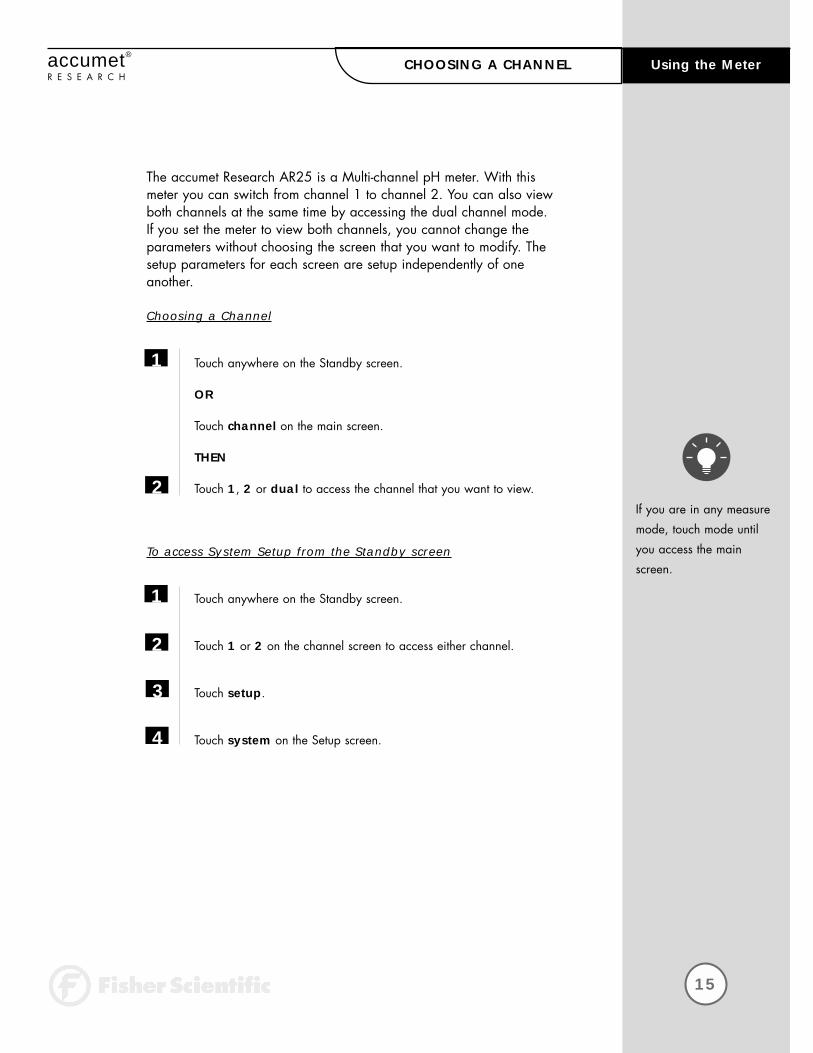
The accumet Research AR25 is a Multi-channel pH meter. With thismeter you can switch from channel 1 to channel 2. You can also viewboth channels at the same time by accessing the dual channel mode. If you set the meter to view both channels, you cannot change the parameters without choosing the screen that you want to modify. Thesetup parameters for each screen are setup independently of one another.
Choosing a Channel
Touch anywhere on the Standby screen.
OR
Touch channel on the main screen.
THEN
Touch 1, 2 or dual to access the channel that you want to view.
To access System Setup from the Standby screen
Touch anywhere on the Standby screen.
Touch 1 or 2 on the channel screen to access either channel.
Touch setup.
Touch system on the Setup screen.
1
2
1
2
3
4

16
accumet®
R E S E A R C HBUTTON FUNCTIONS
The touch screen of your accumet Research pH meter has “buttons” along theright side of the screen that are common to many of the screens. The followingindicates the function of these common buttons.
channel
stdby
mode
enter
exit
save
help
close
more
back
Using the Meter
This button allows you to access the channel screen to choose whatchannel you want to view. This button appears only on multichannelmeters such as the accumet AR25 and AR50. This button also allowsyou to move from the main mode screen to the channel screen to accessthe standby mode.
The mode button allows you to switch between the various operationsof the meter. These operations, depending upon which meter you have,include four measuring modes (pH, mV, ion, conductivity) as well as asetup mode.
The enter button allows you to accept any changes that you have madeon setup screens or accept values that you have input with keypads.When touched, enter will save the changes and return you to the previousscreen.
The save button allows you to save multiple changes you have made onone screen as a group. It functions like the enter button does for individualchanges.
The help button allows you to access helpful information on any screen.When you touch the help button, information about the current screenappears. This information will include step-by-step instructions for operatingthe meter from the current screen and possible applications information forthat screen.
The close key appears on the bottom of all help screens and allows youto exit the help screen and return to the previous screen.
The more button appears on the help screens and allows you toadvance to the next help screen for additional information.
The back button appears on the help screens and allows you to move back to a previous help screen.
The exit button allows you to leave the screen you are currently viewingand return to the previous screen without making any changes.
This is the standby button and it allows you to access the standbymode. When in standby, the meter will not take measurements. It is in astate of rest. When you touch stdby the meter will return to the standbyscreen which says “Fisher Scientific” and displays the time.

17
Using the Meteraccumet®
R E S E A R C HBUTTON FUNCTIONS
meas
std
setup
edit
clear
BS
delete
prev
next
This button accesses the standardization screen from the variousmeasure modes and initiates standardization of the meter once thestandardization screen is accessed.
This button is the measure button and directs the meter to measure yoursample when in the Auto Read function of the pH or Ion modes.
This button will access the setup screens for the measuring mode thatyou are currently using. It can also be used to access the system setupscreen that allows you to set parameters that are not related to measure-ments such as the time and the date.
The print button will send information to the output device that youhave connected to your accumet meter. The output device can be aprinter, data logger or a computer. In addition to this, touching the printbutton will also send data to the data storage center of the meter if asample ID# has been assigned to your sample.
The arrow keys on the screen move the cursor up and down in orderto highlight parameters that you would like to review or edit.
The edit button appears on the setup screens. After you have highlighteda parameter that you would like to change, the edit button allows you toaccess the available options for that parameter.
The BS button is a backspace button. It appears on keypad screens andit allows you to back up and delete a character entered in error.
The delete button appears on the “View Stored Data” screens. Thisbutton allows you to erase the data from the memory of the meter.
The prev button appears on the Data Screens when the data stored inthe meter’s memory has been accessed. It allows you to scroll throughdata points sorted and stored prior to the current data point displayed.
The next button appears on the Data Screens when the data stored in the meter’s memory has been accessed. It allows you to scroll through data points sorted and stored after the current datapoint displayed.
The clear button allows you to remove a setup parameter or standardbuffer value from the meter’s memory that may have been entered at aprevious time or by a previous user that is no longer of value to you.Touching the clear button erases the value so you may enter a new one.It can also erase a parameter that you may have entered erroneously.

18
Setup Operations accumet®
R E S E A R C HSYSTEM SETUP
System Setup
edit
exit
help
SYSTEM SETUP OPTIONS
- Select Language
- Set Date
- Set Time
- Set Beeper Status
- Select Procedural Level
- Set Print Configuration
- Set Operator
- Set Display Contrast
- Display Meter Information
- Reset to Factory Defaults
19
accumet®
R E S E A R C HTABLE OF CONTENTS Setup Operations
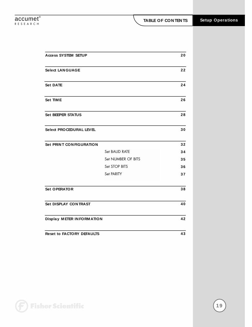
Access SYSTEM SETUP
Select LANGUAGE
Set DATE
Set TIME
Set BEEPER STATUS
Select PROCEDURAL LEVEL
Set PRINT CONFIGURATION
Set OPERATOR
Set DISPLAY CONTRAST
Display METER INFORMATION
Reset to FACTORY DEFAULTS
20
22
24
26
28
30
32
34
35
36
37
38
40
42
43
Set BAUD RATE
Set NUMBER OF BITS
Set STOP BITS
Set PARITY
20
System Setup accumet®
R E S E A R C HAccess SYSTEM SETUP
System Setup
edit
exit
help
SYSTEM SETUP OPTIONS
- Select Language
- Set Date
- Set Time
- Set Beeper Status
- Select Procedural Level
- Set Print Configuration
- Set Operator
- Set Display Contrast
- Display Meter Information
- Reset to Factory Defaults
Select from the options to the right
pH
mV
Ion
setup
channelSeptember 17, 1997 11:11 am
FisherScientific
accumet®AR25
Select your desired measurement channel
stdby
help
FisherScientific
accumet®AR25
dual
1
2
September 17, 1997 11:11 am
Setup
Ion
system
exit
Select from the setup options to the right
mV
pH
21
System Setupaccumet®
R E S E A R C HAccess SYSTEM SETUP
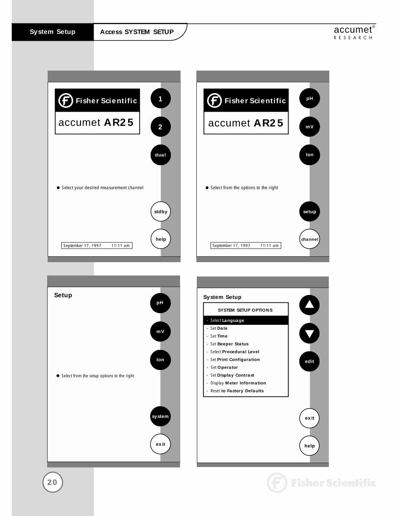
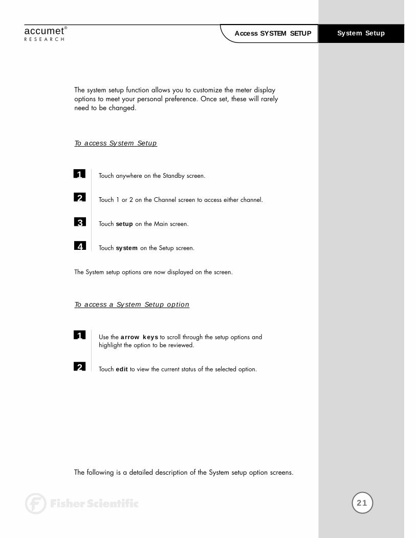
The system setup function allows you to customize the meter displayoptions to meet your personal preference. Once set, these will rarelyneed to be changed.
To access System Setup
Touch anywhere on the Standby screen.
Touch 1 or 2 on the Channel screen to access either channel.
Touch setup on the Main screen.
Touch system on the Setup screen.
The System setup options are now displayed on the screen.
To access a System Setup option
Use the arrow keys to scroll through the setup options and highlight the option to be reviewed.
Touch edit to view the current status of the selected option.
1
2
3
1
2
The following is a detailed description of the System setup option screens.
4

22
System Setup accumet®
R E S E A R C HSelect LANGUAGE
Remember, HELP is always
just a touch of the button
away.
Select Language
enter
exit
help
Use arrow keys to highlight desiredlanguage and then touch enter to accept
Current LANGUAGE
English
French
English

23
System Setupaccumet®
R E S E A R C HSelect LANGUAGE
This option allows you to choose the language in which all prompts and directions will appear on the touch screen.
To Select Language
Access the Select Language screen from the System Setup screen. The current language is displayed on the screen.
Use the arrow keys to highlight the desired language.
Touch enter to accept the language and return to the System Setup screen.
OR
Touch exit to return to the System Setup screen, without making any changes.
1
2
3

24
System Setup accumet®
R E S E A R C HSet DATE
Set Date
D/M/Y
exit
help
Touch clear to delete current date
enter
Use numeric touchpad to input the newdate and then touch enter to accept
1 2 3
4 5 6
7 8 9
0
Current MM/DD/YY 11/11/97
clear
BS /

25
System Setupaccumet®
R E S E A R C HSet DATE
If you do not use the /,
the meter will not accept
the date.
This screen can be used to set the present date which will be displayedon the measure screens. This date will also be printed on demand andstored in the data storage center of the meter when data is saved. Thereare two format options for the date: month/day/year (M/D/Y) or theEuropean format of day/month/year (D/M/Y).
To Set Date
Access the Set Date screen from the System Setup screen. The current date and numeric keypad are displayed on the screen.
Touch clear to delete the current entry.
Touch D/M/Y or M/D/Y to set the date format.
Use the numeric touch pad to enter the desired date, separating theday, the month and the year by touching the / key on the keypad.
Touch enter to accept the date in the current format.
OR
Touch exit to return to the System Setup screen, without making any changes.
1
2
3
4
5

26
System Setup accumet®
R E S E A R C HSet TIME
Set Timeenter
exit
helpUse numeric touchpad to input the new time and then touch enter to accept
24hr
pm
Touch clear to delete current time setting
1 2 3
4 5 6
7 8 9
0 :BS
Current 12HR 10:40 am
clear

27
System Setupaccumet®
R E S E A R C HSet TIME
If you do not use the :, themeter will not accept thetime.
This screen can be used to set the present time which will be displayedon the measure screens. This time will also be printed on demand andstored in the data storage center of the meter when data is saved. There are two format options for the time. The clock can be set as either a 12 hour clock or a 24 hour clock.
To Set Time
Access the Set Time screen from the System Setup screen. The current time and numeric keypad are displayed on the screen.
Touch clear to delete the current entry.
Touch the 24hr or 12hr button to format the clock as either a 12 hour or a 24 hour clock.
Touch am or pm to set the appropriate time.
Use the numeric touch pad to enter the desired time, separating the hour and the minutes by touching the : key on the keypad.
Touch enter to accept the time in the current format.
OR
Touch exit to return to the System Setup screen, without making any changes.
1
2
3
4
5
6
Current 12HR 5:15 pm
Current 24HR 17:15

28
System Setup accumet®
R E S E A R C HSet BEEPER STATUS
Remember, HELP is always
just a touch of the button
away.
Set Beeper Status
ON
exit
help
Use arrow keys to highlight beeperoption and then touch ON/OFF to change
save
Current BEEPER STATUS
After STABLE Reading ON
After KEY Touch OFF
On LIMIT Exceeded ON
Touch save to accept changes
29
System Setupaccumet®
R E S E A R C HSet BEEPER STATUS
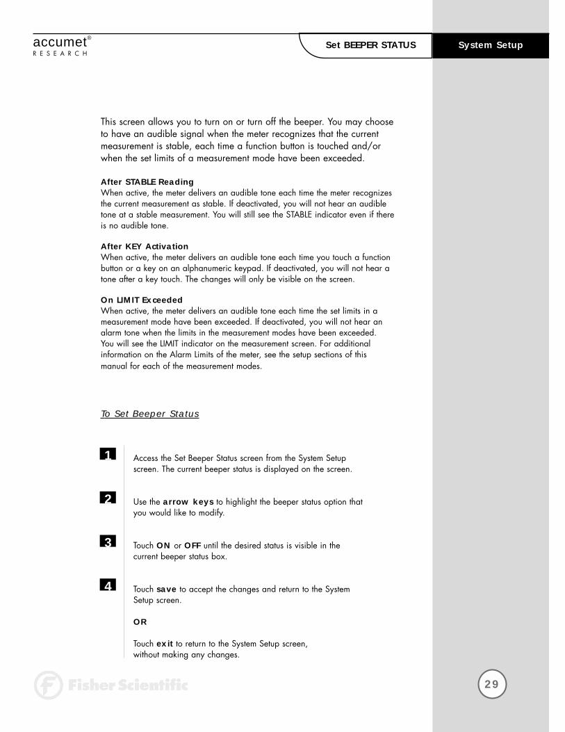
This screen allows you to turn on or turn off the beeper. You may chooseto have an audible signal when the meter recognizes that the currentmeasurement is stable, each time a function button is touched and/orwhen the set limits of a measurement mode have been exceeded.
After STABLE Reading When active, the meter delivers an audible tone each time the meter recognizesthe current measurement as stable. If deactivated, you will not hear an audibletone at a stable measurement. You will still see the STABLE indicator even if thereis no audible tone.
After KEY ActivationWhen active, the meter delivers an audible tone each time you touch a functionbutton or a key on an alphanumeric keypad. If deactivated, you will not hear atone after a key touch. The changes will only be visible on the screen.
On LIMIT ExceededWhen active, the meter delivers an audible tone each time the set limits in ameasurement mode have been exceeded. If deactivated, you will not hear analarm tone when the limits in the measurement modes have been exceeded. You will see the LIMIT indicator on the measurement screen. For additional information on the Alarm Limits of the meter, see the setup sections of this manual for each of the measurement modes.
To Set Beeper Status
Access the Set Beeper Status screen from the System Setup screen. The current beeper status is displayed on the screen.
Use the arrow keys to highlight the beeper status option that you would like to modify.
Touch ON or OFF until the desired status is visible in the current beeper status box.
Touch save to accept the changes and return to the System Setup screen.
OR
Touch exit to return to the System Setup screen, without making any changes.
1
2
3
4

30
System Setup accumet®
R E S E A R C HSelect PROCEDURAL LEVEL
Select Procedural Levelenter
LEVEL 1 - Basic Level
LEVEL 2 - Advanced Level
1
2
Current LEVEL 1
25.0 °C
100%
September 17, 1997 11:11 am
Procedural Level 1
Temperature
Electrode Performance
ATC
slope
mV
25.0 °C
100%
0000.0
September 17, 1997 11:11 amID#
auto buffer
auto read
00000
ON
ON
Procedural Level 2

31
System Setupaccumet®
R E S E A R C HSelect PROCEDURAL LEVEL
This Selection screen allows you to choose the amount of information that you want to have displayed on the screen. There are two levels to choose from. Both of the levels provide identical results. The amount of information appearing on the measure screens and the number ofsetup parameters you can manipulate will vary from Basic to Advancedprocedural levels.
LEVEL 1 - Basic Level This level option offers a full set of prompts to guide you through the basic operation of the meter. The information provided on the screen is minimal toreduce clutter. It includes the measurement and the last standardization time and buffer values. The data box at the bottom of the measure screen includes thecurrent date, time, sample temperature and the electrode performance. In addition to the limited information appearing on the measure screen, there are also fewer options available to you in the setup screens of the various measurement modes.
LEVEL 2 - Advanced Level This option allows you access to all of the features available on the meter. A full set of prompts is available on virtually every screen to lead you through the operation of the meter. You are also given access to all setup parameters forthe various measurement modes. Any parameter not appearing on the BasicLevel Setup screens will maintain the value previously set in the Advanced LevelSetup screens. They will not automatically default to factory default settings. Thisis ideal if you want to “lock” in a parameter in the Advanced Level and switch tothe Basic Level so others cannot accidentally modify the parameter.
To Select Procedural Level
Access the Select Procedural Level screen from the System Setup screen. The current procedural level is displayed on the screen.
Use the numbered buttons on the right of the screen to select the desired procedural level.
Touch enter to accept the procedural level and return to the SystemSetup screen.
OR
Touch exit to return to the System Setup screen, without making any changes.
1
2
3

32
System Setup accumet®
R E S E A R C HSet PRINT CONFIGURATION
Set Print Configuration
edit
exit
help
Use arrow keys to highlight desiredprint setting and then touch edit to change
save
Current PRINT CONFIGURATION
19200
8
1
NONE
- Baud Rate
- # of Bits
- # of Stop
- # Parity
Touch save to save the print settings
33
System Setupaccumet®
R E S E A R C HSet PRINT CONFIGURATION
You can adjust the print configuration of the meter from this screen. The configuration of the following screens must match the configurationof the printer or computer to which the data will be sent.
To Set Print Configuration
Access the Print Configuration screen from the System Setup screen.The current Print Configuration is displayed on the screen.
Use the arrow keys to highlight the configuration option to be modified.
Touch edit to access the parameters for the highlighted option.
OR
Touch exit to return to the System Setup screen, without making any changes.
1
2
3
34
System Setup accumet®
R E S E A R C HSet BAUD RATE
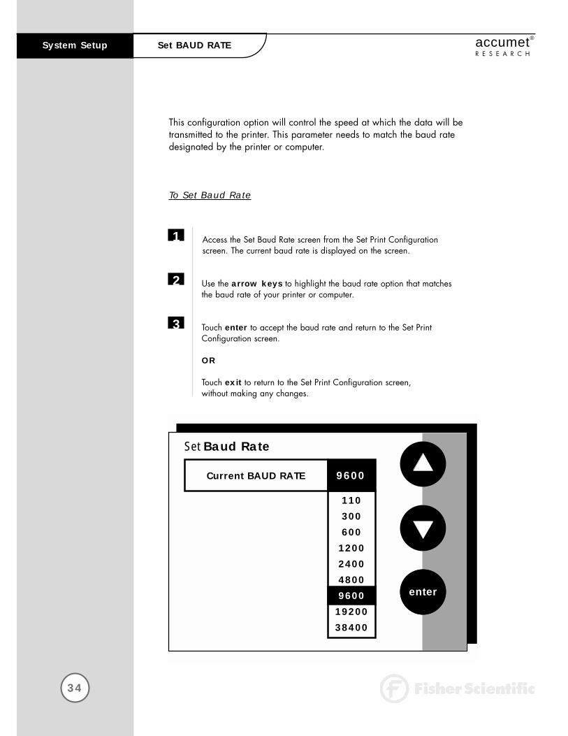
This configuration option will control the speed at which the data will betransmitted to the printer. This parameter needs to match the baud ratedesignated by the printer or computer.
To Set Baud Rate
Access the Set Baud Rate screen from the Set Print Configurationscreen. The current baud rate is displayed on the screen.
Use the arrow keys to highlight the baud rate option that matches the baud rate of your printer or computer.
Touch enter to accept the baud rate and return to the Set PrintConfiguration screen.
OR
Touch exit to return to the Set Print Configuration screen, without making any changes.
1
2
3
Set Baud Rate
Current BAUD RATE
enter
9600
110300600
1200240048009600
1920038400

35
System Setupaccumet®
R E S E A R C HSet NUMBER OF BITS
To Set Number of Bits
Access the Set Number of Bits screen from the Set Print Configurationscreen. The current number of bits is displayed on the screen.
Touch 7 or 8 to select the number of bits.
Touch enter to accept the bit value and return to the Set PrintConfiguration screen.
OR
Touch exit to return to the Set Print Configuration screen, without making any changes.
1
2
3
Set Number of Bits
Current NUMBER OF BITSenter
7
8
36
System Setup accumet®
R E S E A R C HSet STOP BITS
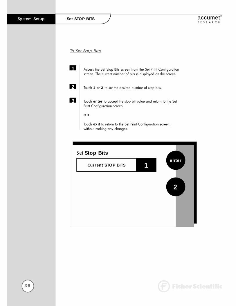
To Set Stop Bits
Access the Set Stop Bits screen from the Set Print Configuration screen. The current number of bits is displayed on the screen.
Touch 1 or 2 to set the desired number of stop bits.
Touch enter to accept the stop bit value and return to the Set Print Configuration screen.
OR
Touch exit to return to the Set Print Configuration screen, without making any changes.
1
2
3
Set Stop Bits
Current STOP BITSenter
1
2

37
System Setupaccumet®
R E S E A R C HSet PARITY
To Set Parity
Access the Set Parity screen from the Set Print Configuration screen. The current Parity is displayed on the screen.
Touch ODD or EVEN or NONE to set the desired parity.
Touch enter to accept the parity setting and return to the Set Print Configuration screen.
OR
Touch exit to return to the Set Print Configuration screen, without making any changes.
1
2
3
Set Parity
Current PARITYenter
NONE
EVEN
ODD

38
System Setup accumet®
R E S E A R C HSet OPERATOR
Set Operatorenter
exit
help
A B C 1
D E F 2
G H I 3
J K L 4
M N O 5
P Q R 6
S T U 7
V W X 8
Y Z 9
BS / . 0
clear
Current Operator
39
System Setupaccumet®
R E S E A R C HSet OPERATOR
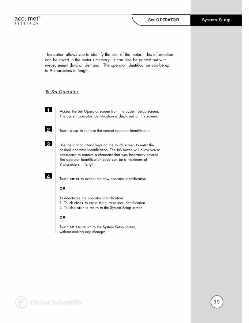
This option allows you to identify the user of the meter. This informationcan be saved in the meter’s memory. It can also be printed out withmeasurement data on demand. The operator identification can be upto 9 characters in length.
To Set Operator
Access the Set Operator screen from the System Setup screen. The current operator identification is displayed on the screen.
Touch clear to remove the current operator identification.
Use the alphanumeric keys on the touch screen to enter the desired operator identification. The BS button will allow you to backspace to remove a character that was incorrectly entered. The operator identification code can be a maximum of 9 characters in length.
Touch enter to accept the new operator identification.
OR
To deactivate the operator identification:1. Touch clear to erase the current user identification.2. Touch enter to return to the System Setup screen.
OR
Touch exit to return to the System Setup screen, without making any changes.
1
2
3
4
System Setup
40
accumet®
R E S E A R C HSet DISPLAY CONTRAST
Set Display Contrast
save
exit
help
Touch lighter or darker to adjust contrast and then touch save to accept
17lighter
darker
The value displayed ranges from 0 (darkest) to 25 (lightest)

41
System Setupaccumet®
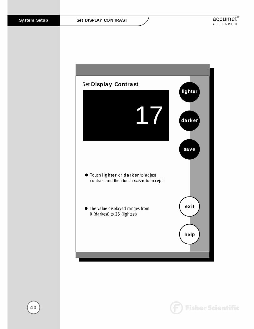
R E S E A R C HSet DISPLAY CONTRAST
This option allows you to change the contrast on the screen to improvethe readability of the information presented on the screen. The numberingsystem that appears on the screen is from 0 to 25. The darkest setting is0 and the lightest setting is 25.
To Set Display Contrast
Access the Set Display Contrast screen from the System Setup screen. The current display contrast value is displayed on the screen.
Use the lighter or darker button to adjust the contrast of the screen to the desired level.
Touch save to accept the contrast setting and return to the System Setup screen.
OR
Touch exit to return to the System Setup screen, without making any changes.
Note: The display contrast of the screen is affected by the internal temperature of the meter. The meter will warm up after being plugged in. During this period(approximately 20 minutes), the display contrast of the screen will get lighter. Youmay need to adjust the contrast during this period to meet your specifications.
1
2
3

42
System Setup accumet®
R E S E A R C HDISPLAY METER INFORMATION
This screen displays the model number, serial number and current software revision of your meter.
Unit Serial Number:
Software Revision:
exit
FisherScientific
accumet®AR25
AR71202101
1.00
43
System Setupaccumet®
R E S E A R C HReset To FACTORY DEFAULTS
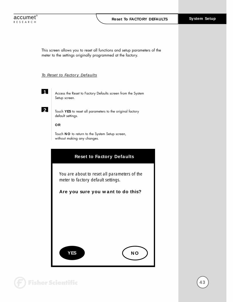
This screen allows you to reset all functions and setup parameters of themeter to the settings originally programmed at the factory.
To Reset to Factory Defaults
Access the Reset to Factory Defaults screen from the System Setup screen.
Touch YES to reset all parameters to the original factory default settings.
OR
Touch NO to return to the System Setup screen, without making any changes.
1
2
You are about to reset all parameters of the meter to factory default settings.
Are you sure you want to do this?
Reset to Factory Defaults
NOYES
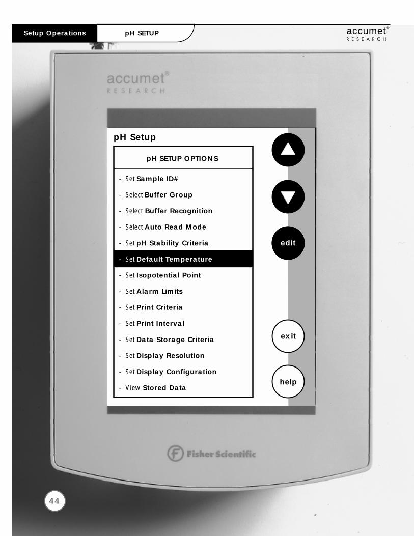
pH Setup
edit
exit
help
pH SETUP OPTIONS
- Set Sample ID#
- Select Buffer Group
- Select Buffer Recognition
- Select Auto Read Mode
- Set pH Stability Criteria
- Set Default Temperature
- Set Isopotential Point
- Set Alarm Limits
- Set Print Criteria
- Set Print Interval
- Set Data Storage Criteria
- Set Display Resolution
- Set Display Configuration
- View Stored Data
44
Setup Operations accumet®
R E S E A R C HpH SETUP
Access pH SETUP
Set SAMPLE ID#
Select BUFFER GROUP
Set pH CUSTOM BUFFER GROUP
Select BUFFER RECOGNITION
Select AUTO READ MODE
Set pH STABILITY CRITERIA
Set DEFAULT TEMPERATURE
Set ISOPOTENTIAL POINT
Set ALARM LIMITS
Set PRINT CRITERIA
Set PRINT INTERVAL
Set DATA STORAGE CRITERIA
Set DISPLAY RESOLUTION
Set DISPLAY CONFIGURATION
View STORED DATA
45
accumet®
R E S E A R C H
The operating parameters of the pH mode can be set and controlled from thepH Setup screen. The following sections will guide you through the variousoptions available for the pH setup mode.
46
48
50
54
56
57
58
60
62
64
66
68
70
72
74
76
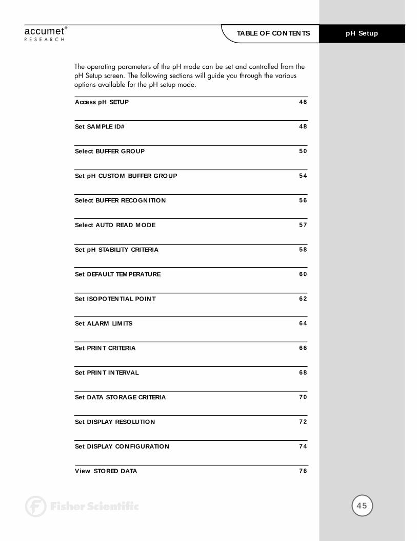
pH SetupTABLE OF CONTENTS

46
accumet®
R E S E A R C H
There are two ways to access the pH Setup screen.
From the Setup screen
Touch setup on the main screen. Touch pH to access the pH Setup screen.
Use the arrow keys to highlight the setup option that you would like to review.
Touch edit to access the screen for the selected option.
1
2
3
pH Setup Access pH SETUP
Select from the options to the right
pH
mV
Ion
setup
channelSeptember 17, 1997 11:11 am
FisherScientific
accumet AR25
Setup
Ion
system
exit
Select from the setup options to the right
mV
pH
pH Setup
edit
exit
help
pH SETUP OPTIONS
- Set Sample ID#
- Select Buffer Group
- Select Buffer Recognition
- Select Auto Read Mode
- Set pH Stability Criteria
- Set Default Temperature
- Set Isopotential Point
- Set Alarm Limits
- Set Print Criteria
- Set Print Interval
- Set Data Storage Criteria
- Set Display Resolution
- Set Display Configuration
- View Stored Data
47
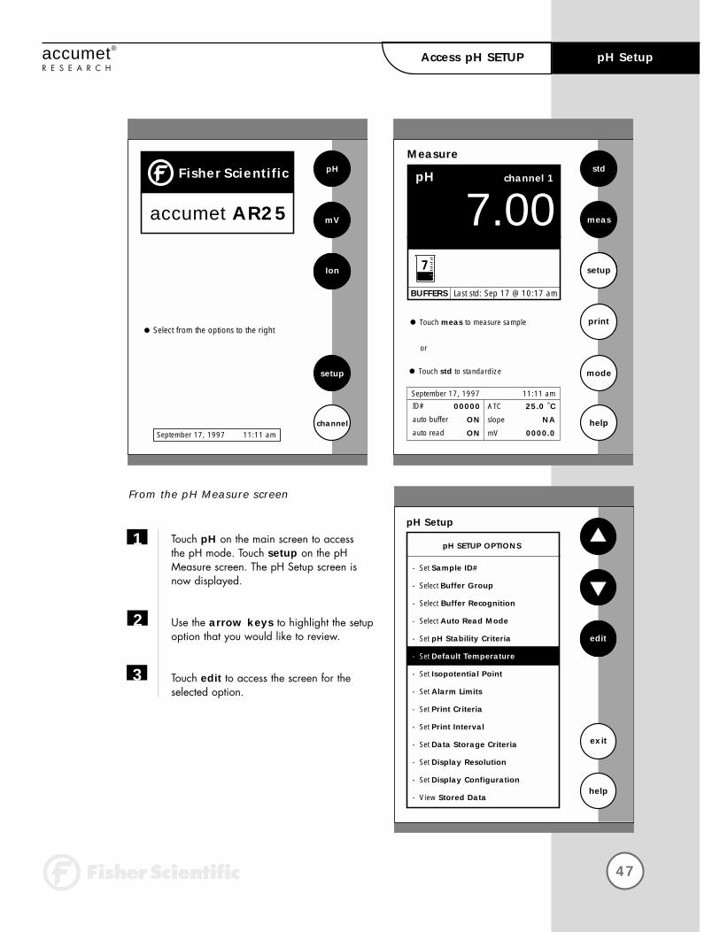
accumet®
R E S E A R C H
From the pH Measure screen
Touch pH on the main screen to access the pH mode. Touch setup on the pH Measure screen. The pH Setup screen is now displayed.
Use the arrow keys to highlight the setupoption that you would like to review.
Touch edit to access the screen for the selected option.
1
2
3
pH SetupAccess pH SETUP
Select from the options to the right
pH
mV
Ion
setup
channelSeptember 17, 1997 11:11 am
FisherScientific
accumet AR25
Measure
07.00pH
std
meas
setup
mode
help
Touch meas to measure sample print
channel 1
Touch std to standardize
or
ATC
slope
mV
25.0 °C
NA
0000.0
September 17, 1997 11:11 amID#
auto buffer
auto read
00000
ON
ON
BUFFERS Last std: Sep 17 @ 10:17 am
7
pH Setup
edit
exit
help
pH SETUP OPTIONS
- Set Sample ID#
- Select Buffer Group
- Select Buffer Recognition
- Select Auto Read Mode
- Set pH Stability Criteria
- Set Default Temperature
- Set Isopotential Point
- Set Alarm Limits
- Set Print Criteria
- Set Print Interval
- Set Data Storage Criteria
- Set Display Resolution
- Set Display Configuration
- View Stored Data
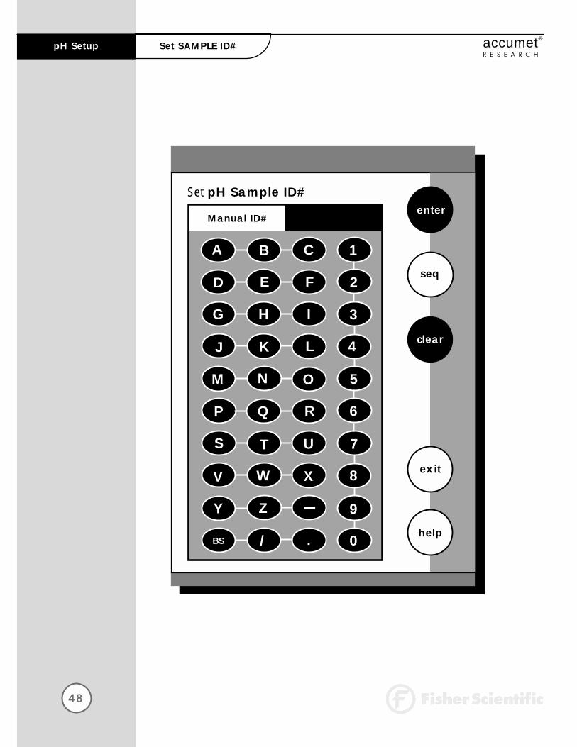
48
pH Setup accumet®
R E S E A R C HSet SAMPLE ID#
Set pH Sample ID#enter
exit
help
A B C 1
D E F 2
G H I 3
J K L 4
M N O 5
P Q R 6
S T U 7
V W X 8
Y Z 9
BS / . 0
clear
Manual ID#
seq

49
pH Setupaccumet®
R E S E A R C HSet SAMPLE ID#
When this option is active, each time you touch print on the Measurescreen the pH value along with the date/time/channel and the sampleID# will be sent to data storage. (See Data Storage Criteria page 99 for additional information on saved parameters.) You can manually enteran alphanumeric identification number of up to 10 characters for anysample or you can have the meter sequentially number your samplesbeginning at the number of your choice. You may also choose to deactivate the sample ID#.
To Set Sample ID#
Manual ID# Assignment
Access the Set Sample ID# screen from the pH (mV, Ion) Setup screen.
Touch man for manual ID# entry. The current ID# is displayed on the screen.
Touch clear to delete the current ID#.
Use the alphanumeric keypad on the screen to enter the desired Sample ID#. The BS key will allow you to backspace to remove a character that was incorrectly entered.
Touch enter to accept the current ID# and return to the pH (mV, Ion) Setup screen.
1
2
3
4
5

50
pH Setup accumet®
R E S E A R C HSet SAMPLE ID#
Set pH Sample ID#enter
exit
helpUse numeric touchpad to input the newstarting ID and then touch enter to accept
clear
man
Touch clear to delete current ID
1 2 3
4 5 6
7 8 9
0 .
Sequential ID#
BS

51
accumet®
R E S E A R C H
Sequential ID# Assignment
Access the Set Sample ID# screen from the pH (mV, Ion) Setup screen.
Touch seq for sequential ID# assignment. The current ID# is displayed on the screen.
Touch clear to delete the current ID#.
Use the alphanumeric keypad on the screen to enter the number that you would like your sequential ID# assignment to begin with. Every time you touch print on the Measure screen, the ID# will increase by 1.The BS key will allow you to backspace to remove a character that was incorrectly entered.
Touch enter to accept the first sequential ID# and return to the pH (mV, Ion) Setup screen.
OR
To Deactivate the Sample ID# Assignment
Access the Set Sample ID# screen from the pH (mV, Ion) Setup screen.
Touch man for manual ID# entry. The current ID# is displayed on the screen.
Touch clear to delete the current ID#.
Touch enter. The ID# assignment is now deactivated. No number will be assigned to your samples. The meter will return to the pH (mV, Ion) Setup screen.
OR
Touch exit to return to the pH (mV, Ion) Setup screenwithout making any changes.
1
2
3
4
5
1
2
3
4
pH SetupSet SAMPLE ID#

52
pH Setup accumet®
R E S E A R C HSelect BUFFER GROUP
Remember, HELP is
always just a touch of the
button away.
Select pH Buffer Group
NIST
exit
help
Use keys to display desired buffer group and then touch enter to accept
Current BUFFER GROUP
42 107 12
enter
EURO
custom
USA
53
pH Setupaccumet®
R E S E A R C HSelect BUFFER GROUP
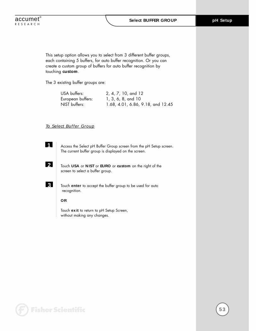
This setup option allows you to select from 3 different buffer groups,each containing 5 buffers, for auto buffer recognition. Or you can create a custom group of buffers for auto buffer recognition by touching custom.
The 3 existing buffer groups are:
USA buffers: 2, 4, 7, 10, and 12European buffers: 1, 3, 6, 8, and 10NIST buffers: 1.68, 4.01, 6.86, 9.18, and 12.45
To Select Buffer Group
Access the Select pH Buffer Group screen from the pH Setup screen.The current buffer group is displayed on the screen.
Touch USA or NIST or EURO or custom on the right of the screen to select a buffer group.
Touch enter to accept the buffer group to be used for autorecognition.
OR
Touch exit to return to pH Setup Screen, without making any changes.
1
2
3

54
pH Setup accumet®
R E S E A R C HSet pH CUSTOM BUFFER GROUP
Set pH Custom Buffer Group
exit
help
Use keys to display desired buffer group and then touch enter to accept
Current BUFFER GROUPenter
edit
CUSTOM
Set pH Custom Buffer Group
exit
help
Use keys to display desired buffer group and then touch enter to accept
Current BUFFER GROUPenter
edit
CUSTOM
1.78 3.65
Set pH Custom Buffer Group
edit
exit
help
Use keys to display desired buffer group and then touch enter to accept
Current BUFFER GROUP
clear
CUSTOM

55
pH Setupaccumet®
R E S E A R C HSet pH CUSTOM BUFFER GROUP
To Set pH Custom Buffer GroupThis option allows you to create a custom buffer group of up to 5 buffers to be used for auto buffer recognition. To obtain optimal results, it is important to maintain at least 2 pH units between selected buffers in the custom group.
Touch custom on the Set pH Buffer Group screen. The current buffer box will show the current custom buffer group.
Touch edit to alter the present group or create a new custom buffergroup. The newly displayed Set pH Custom Buffer Group screen has 5 beakers in the current buffer group box.
Use the arrow keys to highlight the beaker icon with the pH value you want to change. If there are no buffers in the group then proceedto the next step.
Touch edit to add a buffer or make changes to the current buffer group OR touch clear to delete the highlighted buffer value.
Use the numeric keypad that is now displayed to enter the pH buffervalue that you want in your custom buffer set.
Touch enter to accept the value. If you have entered an erroneousvalue, use the BS key on the keypad to erase the last digit entered andcorrect the mistake. If you decide not to change the buffer value on thehighlighted beaker icon, touch exit on the numeric keypad to return tothe Set pH Custom Buffer Group screen.
Repeat steps 3 through 6 to add up to 5 buffers to your custom buffergroup.
Touch exit to return to the Set pH Custom Buffer Group screen to view the current Custom Buffer Group.
Touch enter to accept the group and return to the pH Setup screen, OR touch edit to modify the group and repeat steps 3 through 6.
OR
Touch exit to return to the Set pH Buffer Group screen, without making any changes to the custom buffer group.
1
2
3
4
5
6
7
8
9
If you use the custom
buffer group for auto
buffer recognition, when
you access the Set pH
Buffer Group from the pH
Setup screen, the
current buffer group that
appears on the screen is
the custom buffer group.
In order to access the
edit option for the custom
buffer group, you need to
touch any of the other
buffer group buttons and
then touch custom to
access the edit screen.

This option allows you to select Automatic buffer recognition or manual buffer recognition when standardizing. With the Automatic buffer recognition activated, the meter will automatically recognize the buffers from the chosen buffer group and accept them when the meterrecognizes the reading as stable. When in the Manual buffer recognitionmode, you must enter the buffer value during the standardization procedure. The meter will accept the manually entered buffer when it recognizes that the measurement is stable. During the standardizationprocedure, you may accept the buffer value before the meter recognizesit as stable by touching std.
To Select Buffer Recognition
Access the Select Buffer Recognition screen from the pH Setup screen.The current method of recognition is displayed on the screen.
Touch MAN or AUTO to choose the method of buffer selection.
Touch enter to accept the method of buffer recognition and return to the pH Setup screen.
OR
Touch exit to return to the pH Setup screen, without making any changes.
56
pH Setup accumet®
R E S E A R C HSelect BUFFER RECOGNITION
Regardless of which Buffer
Recognition Mode you
select, STABLE will appear
on the Measure screen
when the meter recognizes
the value as stable.
1
2
3
Select pH Buffer Recognitionenter
Current RECOGNITION
MAN
AUTO

57
pH Setupaccumet®
R E S E A R C HSelect AUTO READ MODE
You can use this meter when the Auto Read function is active or when itis inactive. When the Auto Read function is active, the meter will lockonto a reading when the meter recognizes it as stable. The meter will not deviate from this reading until meas is touched. If the Auto Readfunction is inactive, then the meter will continuously monitor the pH of the sample and the Measure screen display will indicate any fluctuationin the sample pH.
To Select Auto Read Mode
Access the Select Auto Read Mode screen from the pH (Ion) Setup screen. The current Read Mode is displayed on the screen.
Touch AUTO or MAN to choose the desired read mode.
Touch enter to accept the read mode and return to the pH (Ion) Setup screen.
OR
Touch exit to return to the pH (Ion) Setup Screen, without making any changes.
1
2
3
Select pH Auto Read Modeenter
Current MODE
MAN
AUTO

58
pH Setup accumet®
R E S E A R C HSet pH STABILITY CRITERIA
Set pH Stability Criteria
enter
exit
help
Use arrow keys to highlight stabilitycriteria and then touch enter to accept
Current CRITERIA Medium
Fast
Medium
Slow
59
accumet®
R E S E A R C H
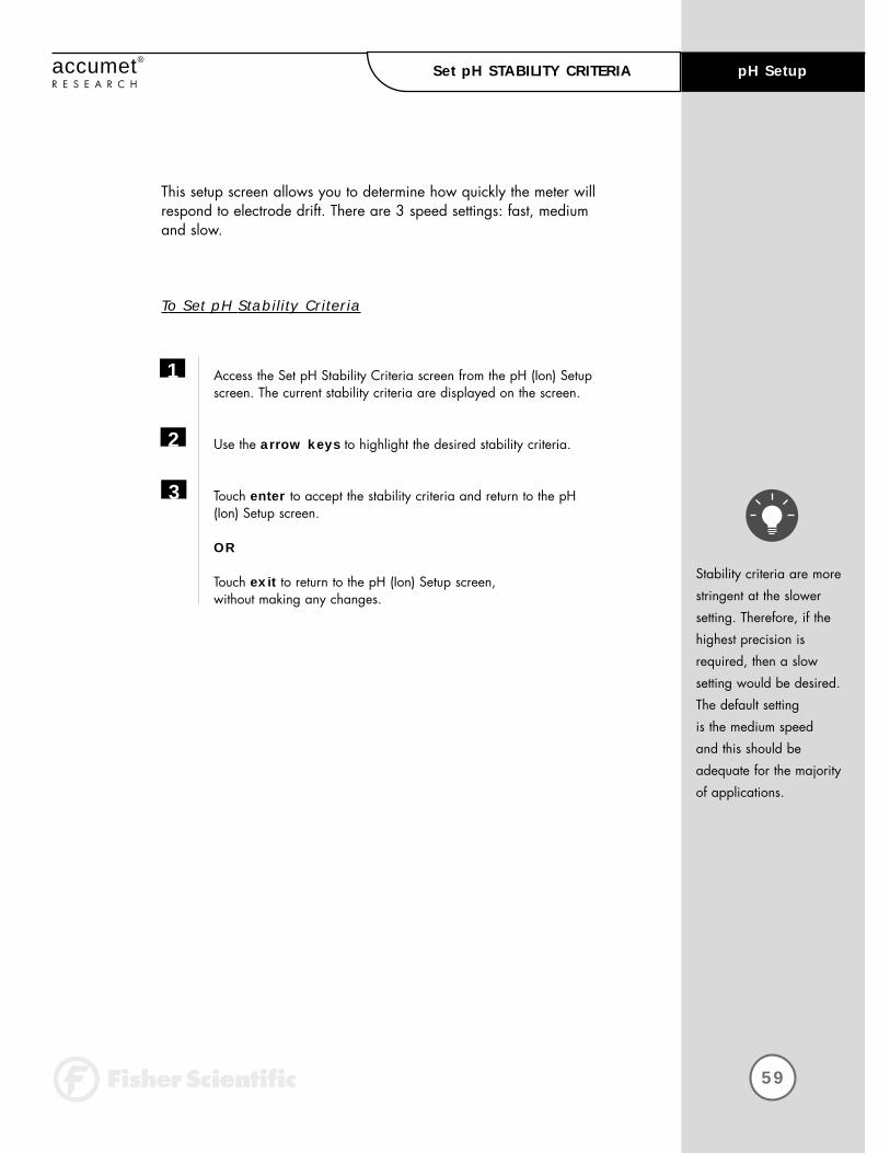
Stability criteria are more
stringent at the slower
setting. Therefore, if the
highest precision is
required, then a slow
setting would be desired.
The default setting
is the medium speed
and this should be
adequate for the majority
of applications.
This setup screen allows you to determine how quickly the meter willrespond to electrode drift. There are 3 speed settings: fast, medium and slow.
To Set pH Stability Criteria
Access the Set pH Stability Criteria screen from the pH (Ion) Setupscreen. The current stability criteria are displayed on the screen.
Use the arrow keys to highlight the desired stability criteria.
Touch enter to accept the stability criteria and return to the pH (Ion) Setup screen.
OR
Touch exit to return to the pH (Ion) Setup screen, without making any changes.
1
2
3
pH SetupSet pH STABILITY CRITERIA
60
pH Setup accumet®
R E S E A R C HSet DEFAULT TEMPERATURE
Set pH Default Temperatureenter
exit
helpUse numeric touchpad to input the newtemperature and then touch enter to accept
clear
F
K
Touch clear to delete current default temp
1 2 3
4 5 6
7 8 9
0 .
25.0 °CCurrent DEFAULT
BS

61
pH Setupaccumet®
R E S E A R C HSet DEFAULT TEMPERATURE
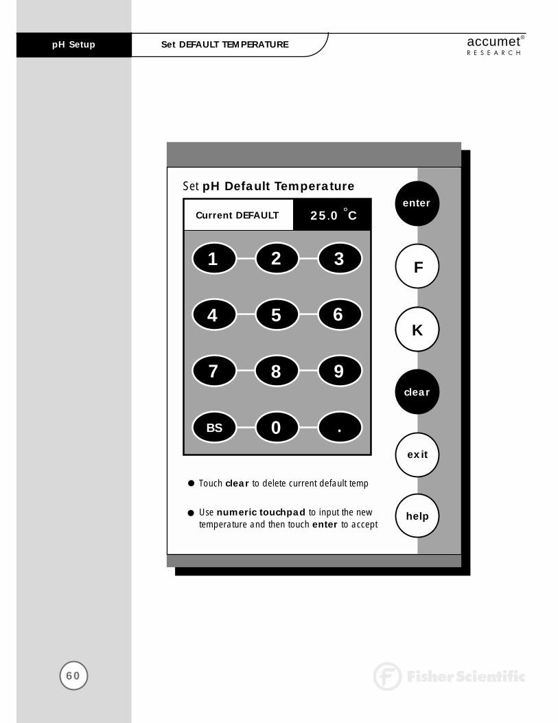
The use of an ATC probe
provides a measured
temperature value to the
meter and will override
any value entered in the
default temperature
screen. This measured
value will be used by
the meter to make pH
(Ion) calculations.
It is a well known fact that pH is a temperature dependent measurement.The factory default setting is 25°C. If you are taking the pH of a solutionthat is not 25°C and you are not using an Automatic TemperatureCompensation (ATC) Probe, then you should enter the temperature valueof that solution in order to get the correct pH value. The current defaulttemperature setting will be displayed when the Set Default Temperaturescreen is displayed.
To Set Default Temperature
Access the Set Default Temperature screen from the pH (Ion) Setup screen. The current default temperature is displayed on the screen.
Touch clear to erase the current temperature value.
Select the temperature units by touching the appropriate unit key C (Celsius), F (Fahrenheit), or K (Kelvin).
Use the numeric keypad to enter the desired default temperature.
Touch enter to accept the temperature setting and return to the pH (Ion) Setup screen.
OR
Touch exit to return to the pH (Ion) Setup screen, without making any changes.
1
2
3
4
5

62
pH Setup accumet®
R E S E A R C HSet ISOPOTENTIAL POINT
Set pH Isopotential Pointenter
exit
helpUse numeric touchpad to input the newIso Point and then touch enter to accept
clear
Touch clear to delete current Iso Point
1 2 3
4 5 6
7 8 9
0 .
0.0 mVCurrent ISO POINT
BS

63
pH Setupaccumet®
R E S E A R C HSet ISOPOTENTIAL POINT
The Isopotential Point is the millivolt reading for an electrode at whichtemperature has no effect on the measurement. pH electrodes are constructed so that the isopotential point is theoretically zero millivolts.This is very close to a pH of 7. Most pH electrodes do not achieve this value precisely. However, they are close enough so that it is not usually necessary to use an isopotential point other than zero. The true isopotential point of any given electrode must be determined experimentally. (See Appendix: Determining Isopotential PointsExperimentally, page 137)
To Set Isopotential Point
Access the Set Isopotential Point screen from the pH (Ion) Setup screen. The current isopotential point is displayed on the screen.
Touch clear to remove the current mV value.
Use the numeric keypad to enter the desired mV setting for the new isopotential point.
Touch enter to accept this value and return to the pH (Ion) Setup screen.
OR
Touch exit to return to the pH (Ion) Setup screen, without making any changes.
1
2
3
4
64
pH Setup accumet®
R E S E A R C HSet ALARM LIMITS
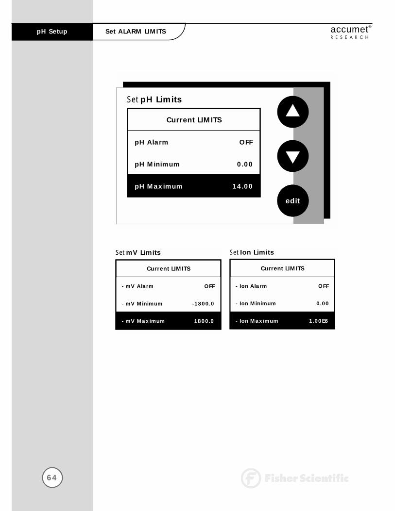
Set pH Limits
edit
Current LIMITS
pH Alarm OFF
pH Minimum 0.00
pH Maximum 14.00
Set mV Limits
Current LIMITS
- mV Alarm OFF
- mV Minimum -1800.0
- mV Maximum 1800.0
Set Ion Limits
Current LIMITS
- Ion Alarm OFF
- Ion Minimum 0.00
- Ion Maximum 1.00E6

65
pH Setupaccumet®
R E S E A R C HSet ALARM LIMITS
This option allows you to set alarm limits for the pH measuring mode. Ifthe pH value of the measurement is outside of the boundaries set by theminimum and maximum limits, an audible alarm and/or a visual warningwill appear to let you know that your sample measurement was outside ofthe set limits.
To Set Alarm Limits
Access the Set Alarm Limits screen from the pH (mV, Ion) Setup screen. The current alarm limits are displayed on the screen.
Use the arrow keys to highlight the pH (mV, Ion) Alarm option you want to modify.
Touch ON or OFF to set the status of the alarm for the pH (mV, Ion) mode.
Use the arrow keys to highlight the desired pH (mV, Ion) alarm limit.
Touch edit to change the value.
Use the keypad to enter the new limit value.
Touch enter on the keypad to accept this limit and return to the Set pH (mV, Ion) Limits screen. If you do not want to change the limit value, you can touch exit on the keypad and return to the Set pH (mV, Ion) Limits screen.
Repeat steps 4 through 7 to set the other pH (mV, Ion) Alarm limit.
OR
Touch exit to return to the pH (mV, Ion) Setup screen, without making any changes.
1
2
3
4
5
6
7
8

66
pH Setup accumet®
R E S E A R C HSet PRINT CRITERIA
Set pH Print Criteria
Current PRINT CRITERIA
- Date/Time/Channel ON
- Sample ID# ON
- pH measurement ON
- Temperature - ATC ON
- Last Standardization OFF
- Current Buffers OFF
- Slope ON
- mV measurement ON
- Meter model #/serial # ON
- Operator ON
Set mV Print Criteria
Current PRINT CRITERIA
- Date/Time/Channel ON
- Sample ID# ON
- mV measurement ON
- Temperature - ATC ON
- Meter model #/serial # ON
- Operator ON
Set Ion Print Criteria
Current PRINT CRITERIA
- Date/Time/Channel ON
- Sample ID# ON
- Ion measurement ON
- Temperature - ATC ON
- Last Standardization OFF
- Current Standards OFF
- Slope ON
- mV measurement ON
- Meter model #/serial # ON
- Operator ON
- electrode/method ON

67
pH Setupaccumet®
R E S E A R C HSet PRINT CRITERIA
The Date/Time/Channel
option and the
Measurement option
are always active
and cannot be deactivat-
ed. These criteria will
always be printed.
Because they can not be
changed, they will not be
highlighted when using
the arrow keys.
This screen allows you to select which criteria are printed with the measurement when you print the data or send it to a computer. The status of the current print criteria is displayed on the screen. The criteria option is active if “ON” appears to the right of the option. It is inactive if “OFF” appears to the right of the option. Any active criteria will be printed on demand.
To Set Print Criteria
Access the Set Print Criteria screen from the pH (mV, Ion) Setup screen. The current print criteria are displayed on the screen.
Use the arrow keys to highlight the print criteria option you want to modify.
Touch ON or OFF change the status of the criteria.
Repeat steps 2 and 3 with the remaining criteria.
Touch save to save the entire group of print criteria and return to the pH (mV, Ion) Setup screen.
OR
Touch exit to return to the pH (mV, Ion) Setup screen, without making any changes.
1
2
3
4
5
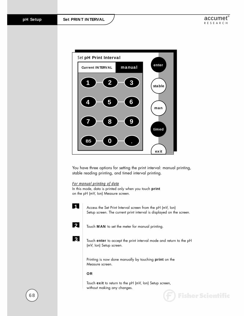
You have three options for setting the print interval: manual printing, stable reading printing, and timed interval printing.
For manual printing of dataIn this mode, data is printed only when you touch printon the pH (mV, Ion) Measure screen.
Access the Set Print Interval screen from the pH (mV, Ion) Setup screen. The current print interval is displayed on the screen.
Touch MAN to set the meter for manual printing.
Touch enter to accept the print interval mode and return to the pH (mV, Ion) Setup screen.
Printing is now done manually by touching print on the Measure screen.
OR
Touch exit to return to the pH (mV, Ion) Setup screen, without making any changes.
68
pH Setup accumet®
R E S E A R C HSet PRINT INTERVAL
1
2
3
Set pH Print Interval
enter
exit
man
1 2 3
4 5 6
7 8 9
0BS
Current INTERVAL
stable
timed
.
manual

69
pH Setupaccumet®
R E S E A R C HSet PRINT INTERVAL
For stable reading printingIn this mode, data is printed every time the meter recognizes the current pH (mV, Ion) measurement as stable.
Access the Set Print Interval screen from the pH (mV, Ion) Setup screen. The current print interval is displayed on the screen.
Touch stable to set the meter for stable reading printing.
Touch enter to accept the print interval mode and return to the pH (mV, Ion) Setup screen.
Printing is now done when the meter recognizes the present reading as stable.
OR
Touch exit to return to the pH (mV, Ion) Setup screen, without making any changes.
For timed interval printingIn this mode, data is printed at the timed interval that you select.
Access the Set Print Interval screen from the pH (mV, Ion) Setup screen. The current print interval is displayed on the screen.
Touch timed to access the timed interval mode and delete the current print interval time.
Use the keypad to enter the desired time for the print interval.
Touch enter to accept the new time interval for printing and return to the pH (mV, Ion) Setup screen.
Printing is now done at the set timed interval.
OR
Touch exit to return to the pH (mV, Ion) Setup screen, without making any changes.
1
2
3
1
2
3
4

70
pH Setup accumet®
R E S E A R C HSet DATA STORAGE CRITERIA
Set pH Data Storage Criteria
Current DATA STORAGE CRITERIA
- Date/Time/Channel ON
- Sample ID# ON
- pH measurement ON
- Temperature - ATC ON
- Last Standardization OFF
- Current Buffers OFF
- Slope ON
- mV measurement ON
- Meter model #/serial # ON
- Operator ON
Set mV Data Storage Criteria
Current DATA STORAGE CRITERIA
- Date/Time/Channel ON
- Sample ID# ON
- mV measurement ON
- Temperature - ATC ON
- Meter model #/serial # ON
- Operator ON
Set Ion Data Storage Criteria
Current DATA STORAGE CRITERIA
- Date/Time/Channel ON
- Sample ID# ON
- Ion measurement ON
- Temperature - ATC ON
- Last Standardization OFF
- Current Standards OFF
- Slope ON
- mV measurement ON
- Meter model #/serial # ON
- Operator ON
- electrode/method ON
71
pH Setupaccumet®
R E S E A R C HSet DATA STORAGE CRITERIA
The Date/Time/Channel
criteria and the
Measurement criteria are
always active and cannot
be deactivated. These
criteria will always be
stored with the measure-
ment value. Because they
can not be changed,
they will not be highlight-
ed when using the
arrow keys.
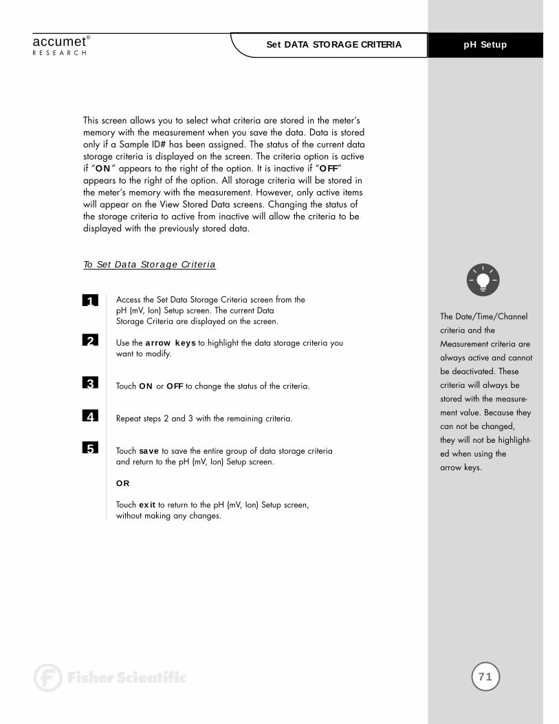
This screen allows you to select what criteria are stored in the meter’smemory with the measurement when you save the data. Data is storedonly if a Sample ID# has been assigned. The status of the current datastorage criteria is displayed on the screen. The criteria option is active if “ON” appears to the right of the option. It is inactive if “OFF”appears to the right of the option. All storage criteria will be stored inthe meter’s memory with the measurement. However, only active itemswill appear on the View Stored Data screens. Changing the status of the storage criteria to active from inactive will allow the criteria to be displayed with the previously stored data.
To Set Data Storage Criteria
Access the Set Data Storage Criteria screen from the pH (mV, Ion) Setup screen. The current Data Storage Criteria are displayed on the screen.
Use the arrow keys to highlight the data storage criteria you want to modify.
Touch ON or OFF to change the status of the criteria.
Repeat steps 2 and 3 with the remaining criteria.
Touch save to save the entire group of data storage criteria and return to the pH (mV, Ion) Setup screen.
OR
Touch exit to return to the pH (mV, Ion) Setup screen, without making any changes.
1
2
3
4
5
72
pH Setup accumet®
R E S E A R C HSet DISPLAY RESOLUTION
Set pH Display Resolutionenter
exit
help
Select desired display resolution and then touch enter to accept
X.X
X.XX
Current RESOLUTION
X.XXX
X.XX
73
pH Setupaccumet®
R E S E A R C HSet DISPLAY RESOLUTION
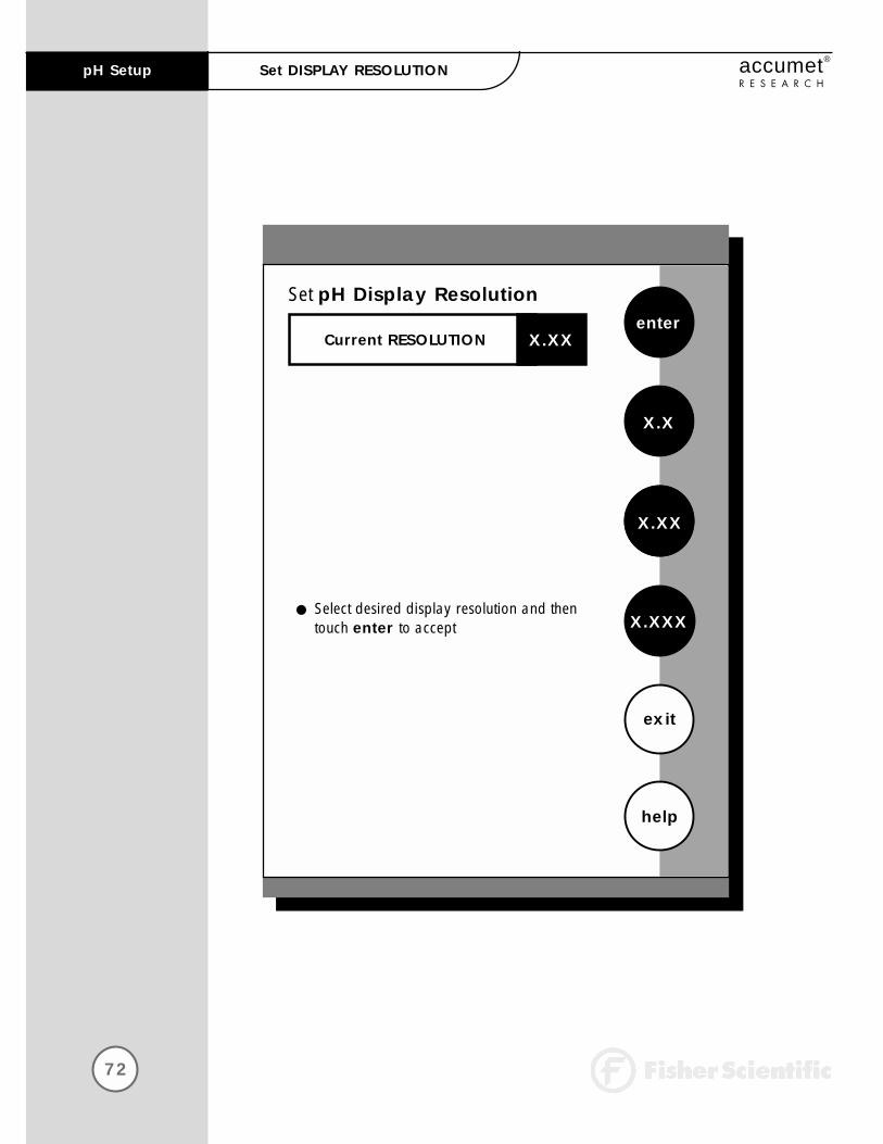
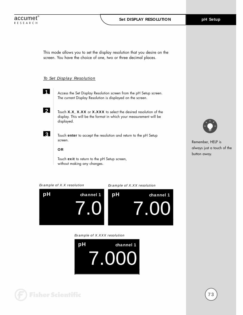
This mode allows you to set the display resolution that you desire on thescreen. You have the choice of one, two or three decimal places.
To Set Display Resolution
Access the Set Display Resolution screen from the pH Setup screen. The current Display Resolution is displayed on the screen.
Touch X.X, X.XX or X.XXX to select the desired resolution of the display. This will be the format in which your measurement will be displayed.
Touch enter to accept the resolution and return to the pH Setup screen.
OR
Touch exit to return to the pH Setup screen, without making any changes.
1
2
3
07.0pH channel 1
Example of X.X resolution
07.00pH channel 1
Example of X.XX resolution
07.000pH channel 1
Example of X.XXX resolution
Remember, HELP is
always just a touch of the
button away.
74
pH Setup accumet®
R E S E A R C HSet DISPLAY CONFIGURATION
Set pH Display Configuration
Current DISPLAY CONFIGURATION
- Last Standardization ON
- Date ON
- Time ON
- measurement channel ON
- sample ID# ON
- auto buffer status ON
- auto read status ON
- temperature ON
- slope ON
- mV Display ON
Set mV Display Configuration
Current DISPLAY CONFIGURATION
- Date ON
- Time ON
- measurement channel ON
- sample ID# ON
- temperature ON
Set Ion Display Configuration
Current DISPLAY CONFIGURATION
- Last Standardization ON
- Date ON
- Time ON
- measurement channel ON
- sample ID# ON
- auto read status ON
- temperature ON
- slope ON
- mV Display ON
- electrode/method ON
75
pH Setupaccumet®
R E S E A R C HSet DISPLAY CONFIGURATION
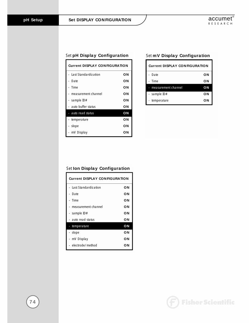
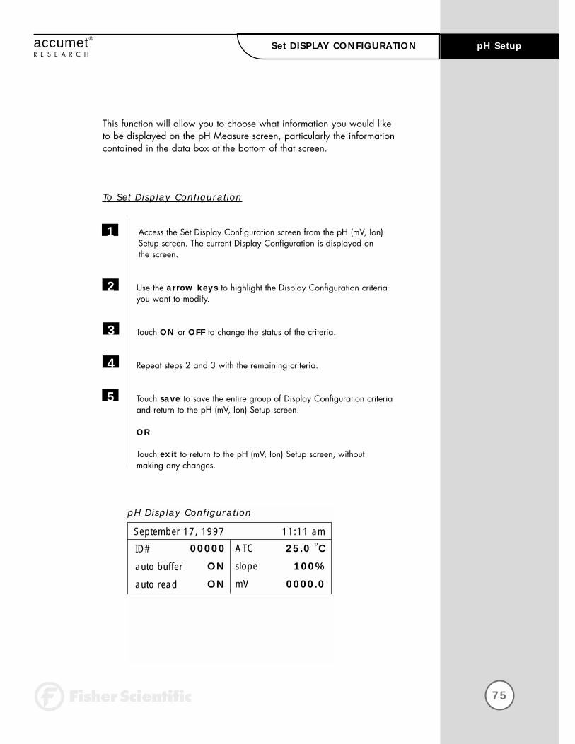
This function will allow you to choose what information you would like to be displayed on the pH Measure screen, particularly the informationcontained in the data box at the bottom of that screen.
To Set Display Configuration
Access the Set Display Configuration screen from the pH (mV, Ion)Setup screen. The current Display Configuration is displayed on the screen.
Use the arrow keys to highlight the Display Configuration criteria you want to modify.
Touch ON or OFF to change the status of the criteria.
Repeat steps 2 and 3 with the remaining criteria.
Touch save to save the entire group of Display Configuration criteriaand return to the pH (mV, Ion) Setup screen.
OR
Touch exit to return to the pH (mV, Ion) Setup screen, without making any changes.
1
2
3
4
5
ATC
slope
mV
25.0 °C
100%
0000.0
September 17, 1997 11:11 am
ID#
auto buffer
auto read
00000
ON
ON
pH Display Configuration

76
pH Setup accumet®
R E S E A R C HView STORED DATA
View Stored Data
enter
exit
help
Use arrow keys to highlight desired sortoption and then touch enter to accept
Data POINTS 17
Sample ID
Date
Operator
77
pH Setupaccumet®
R E S E A R C HView STORED DATA
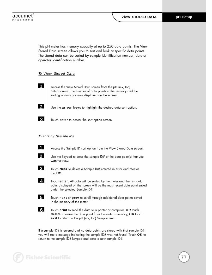
This pH meter has memory capacity of up to 250 data points. The ViewStored Data screen allows you to sort and look at specific data points.The stored data can be sorted by sample identification number, date oroperator identification number.
To View Stored Data
Access the View Stored Data screen from the pH (mV, Ion) Setup screen. The number of data points in the memory and the sorting options are now displayed on the screen.
Use the arrow keys to highlight the desired data sort option.
Touch enter to access the sort option screen.
To sort by Sample ID#
Access the Sample ID sort option from the View Stored Data screen.
Use the keypad to enter the sample ID# of the data point(s) that youwant to view.
Touch clear to delete a Sample ID# entered in error and reenter the ID#.
Touch enter. All data will be sorted by the meter and the first datapoint displayed on the screen will be the most recent data point savedunder the selected Sample ID#.
Touch next or prev to scroll through additional data points saved in the memory of the meter.
Touch print to send the data to a printer or computer, OR touch delete to erase the data point from the meter’s memory, OR touch exit to return to the pH (mV, Ion) Setup screen.
If a sample ID# is entered and no data points are stored with that sample ID#,you will see a message indicating the sample ID# was not found. Touch OK toreturn to the sample ID# keypad and enter a new sample ID#.
1
2
3
1
2
3
4
5
6
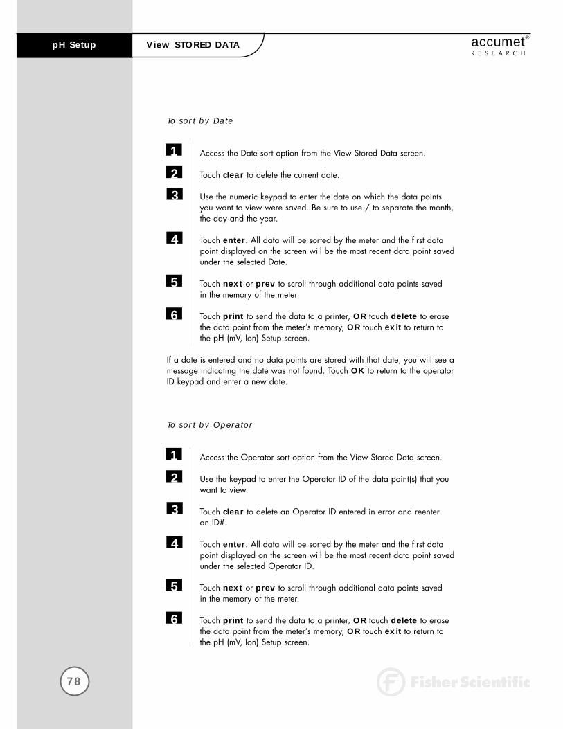
To sort by Date
Access the Date sort option from the View Stored Data screen.
Touch clear to delete the current date.
Use the numeric keypad to enter the date on which the data pointsyou want to view were saved. Be sure to use / to separate the month,the day and the year.
Touch enter. All data will be sorted by the meter and the first datapoint displayed on the screen will be the most recent data point saved under the selected Date.
Touch next or prev to scroll through additional data points saved in the memory of the meter.
Touch print to send the data to a printer, OR touch delete to erase the data point from the meter’s memory, OR touch exit to return to the pH (mV, Ion) Setup screen.
If a date is entered and no data points are stored with that date, you will see amessage indicating the date was not found. Touch OK to return to the operatorID keypad and enter a new date.
To sort by Operator
Access the Operator sort option from the View Stored Data screen.
Use the keypad to enter the Operator ID of the data point(s) that youwant to view.
Touch clear to delete an Operator ID entered in error and reenter an ID#.
Touch enter. All data will be sorted by the meter and the first datapoint displayed on the screen will be the most recent data point saved under the selected Operator ID.
Touch next or prev to scroll through additional data points saved in the memory of the meter.
Touch print to send the data to a printer, OR touch delete to erase the data point from the meter’s memory, OR touch exit to return to the pH (mV, Ion) Setup screen.
78
pH Setup accumet®
R E S E A R C H
1
2
3
4
5
6
View STORED DATA
1
2
3
4
5
6

79
pH Setupaccumet®
R E S E A R C HView STORED DATA
If an operator ID is entered and no data points are stored with that operator ID,you will see a message indicating the operator ID was not found. Touch OK toreturn to the operator ID keypad and enter a new operator ID.
NOTE:Even if you do not know the appropriate information to access a specific data point, you can access the stored data through any of the sort options.Highlight the sort option of interest and touch enter to access the sort screen.Touch enter again and the meter will place you at a data point.
* The sample ID# sort option will place you at the first data point innumeric order by sample ID#.
* The Operator sort option will place you at the data point of the firstoperator ID in alphabetic order.
* The Date sort option will place you at the most recent point on the lastdate that data was stored.
Once you access the data storage center, you can touch prev and next toscroll through the additional data points stored in memory.
View Stored Data
Current STORED DATA
September 17, 199711:11 amChannel: 1
sample ID#: 110Ion value: 1.0Ion method: Known AdditionIon electrode: AMMONIATemperature: 25.0°CLast Std: Sep.17 @11:11amCurrent Stds: 10.0 100Slope: 102.2%mV value: 0.6model#/serial#: AR25/alpha 0001Operator: Tom D.

mV Setup (channel 1)
edit
exit
help
mV SETUP OPTIONS
- Set Sample ID#
- Set Alarm Limit
- Set Print Criteria
- Set Print Interval
- Set Data Storage Criteria
- Set Display Resolution
- Set Display Configuration
- View Stored Data
80
Setup Operations accumet®
R E S E A R C HmV SETUP
81
mV Setupaccumet®
R E S E A R C HTABLE OF CONTENTS
The operating parameters of the mV mode can be set and controlled from themV Setup screen. The following sections will guide you through the variousoptions available for the mV setup mode.
Access mV SETUP
Set SAMPLE ID#
Set ALARM LIMIT
Set PRINT CRITERIA
Set PRINT INTERVAL
Set DATA STORAGE CRITERIA
Set DISPLAY RESOLUTION
Set DISPLAY CONFIGURATION
View STORED DATA
82
84
84
84
85
85
86
85
85
82
mV Setup accumet®
R E S E A R C HAccess mV SETUP
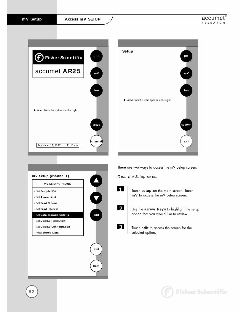
There are two ways to access the mV Setup screen.
From the Setup screen
Touch setup on the main screen. Touch mV to access the mV Setup screen.
Use the arrow keys to highlight the setupoption that you would like to review.
Touch edit to access the screen for the selected option.
1
2
3
Select from the options to the right
pH
mV
Ion
setup
channelSeptember 17, 1997 11:11 am
FisherScientific
accumet AR25
Setup
Ion
system
exit
Select from the setup options to the right
mV
pH
mV Setup (channel 1)
edit
exit
help
mV SETUP OPTIONS
- Set Sample ID#
- Set Alarm Limit
- Set Print Criteria
- Set Print Interval
- Set Data Storage Criteria
- Set Display Resolution
- Set Display Configuration
- View Stored Data
83
mV Setupaccumet®
R E S E A R C HAccess mV SETUP
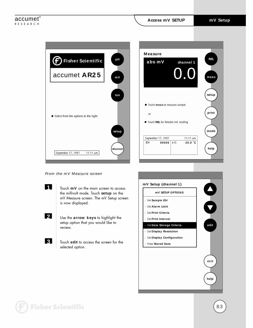
From the mV Measure screen
Touch mV on the main screen to access the millivolt mode. Touch setup on themV Measure screen. The mV Setup screenis now displayed.
Use the arrow keys to highlight thesetup option that you would like toreview.
Touch edit to access the screen for the selected option.
1
2
3
Select from the options to the right
pH
mV
Ion
setup
channelSeptember 17, 1997 11:11 am
FisherScientific
accumet AR25
Measure
00.0abs mV
REL
meas
setup
mode
help
Touch meas to measure sample
channel 1
Touch REL for Relative mV reading
or
ATC 25.0 °CSeptember 17, 1997 11:11 amID# 00000
mV Setup (channel 1)
edit
exit
help
mV SETUP OPTIONS
- Set Sample ID#
- Set Alarm Limit
- Set Print Criteria
- Set Print Interval
- Set Data Storage Criteria
- Set Display Resolution
- Set Display Configuration
- View Stored Data

84
mV Setup accumet®
R E S E A R C H
To Set Sample ID#
When this option is active, each time you touch print on the Measure screen themV value along with the date/time/channel and the sample ID# will be sent todata storage. You can manually enter an alphanumeric identification number ofup to 10 characters for any sample, or you can have the meter sequentially number your samples beginning at the number of your choice. You may also choose to deactivate the sample ID#.
The mV Sample ID# is set the same way as previously described in pH Setup.See page 48 for instructions.
To Set Alarm Limit
This option allows you to set alarm limits for the mV measuring mode. If the mVvalue of the measurement is outside of the boundaries set by the upper andlower limits, an audible alarm and/or a visual warning will appear to let youknow that your sample measurement was outside of the set limits.
The mV Alarm Limits are set the same way as previously described in pH Setup.See page 64 for instructions.
To Set Print Criteria
This screen allows you to select which criteria are printed with the measurementwhen you print the data or send it to a computer. The status of the current printcriteria is displayed on the screen. The criteria option is active if “ON” appearsto the right of the option. It is inactive if “OFF” appears to the right of theoption. Any active criteria will be printed on demand.
The mV Print Criteria are set the same way as previously described in pH Setup.See page 66 for instructions.
Remember, HELP is
always just a touch of
the button away.

85
mV Setupaccumet®
R E S E A R C H
To Set Print Interval
You have three options for setting the print interval: manual printing, stable reading printing, and timed interval printing.
The mV Print Interval is set the same way as previously described in pH Setup.See page 68 for instructions.
To Set Data Storage Criteria
This screen allows you to select what criteria are stored in the meter’s memorywith the measurement when you save the data. The status of the current datastorage criteria is displayed on the screen. The criteria option is active if “ON”appears to the right of the option. It is inactive if “OFF” appears to the right ofthe option. All storage criteria will be stored in the meter’s memory with the mea-surement. However, only active items will appear on the View Stored Datascreens. Changing the status of the storage criteria to active from inactive willallow the criteria to be displayed with the previously stored data.
The mV Data Storage Criteria are set the same way as previously described inpH Setup. See page 70 for instructions.
To Set Display Configuration
This function will allow you to choose what information you would like to be displayed on the mV Measure screen, particularly the information contained in the data box at the bottom of that screen.
The mV Display Configuration is set the same way as previously described in pHSetup. See page 74 for instructions
To View Stored Data
This meter has memory capacity for up to 250 data points. The View StoredData screen allows you to sort and look at specific data points. The stored datacan be sorted by sample identification number, date or operator identificationnumber.
The mV Stored Data is viewed the same way as previously described in pHSetup. See page 76 for instructions.
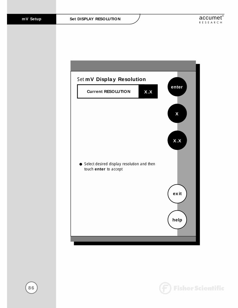
86
mV Setup accumet®
R E S E A R C HSet DISPLAY RESOLUTION
Set mV Display Resolutionenter
exit
help
Select desired display resolution and then touch enter to accept
X
X.X
Current RESOLUTION X.X

87
accumet®
R E S E A R C HSet DISPLAY RESOLUTION mV Setup
To Set Display Resolution
This mode allows you to set the display resolution that you desire on the screen. You have the choice of zero or one decimal place.
Access the Set Display Resolution screen from the mV Setup screen. The current Display Resolution is displayed on the screen.
Touch X or X.X to select the resolution of the display that you desire.This will be the format in which your measurement will be displayed.
Touch enter to accept the resolution and return to the mV setup screen.
OR
Touch exit to return to the mV Setup Screen, without making any changes.
1
2
3
0-177mV channel 1
Example of X resolution
-177.0mV channel 1
Example of X.X resolution

Ion Setup (channel 1)
edit
exit
help
ION SETUP OPTIONS
- Set Sample ID#
- Select Ion Method
- Select Measurement Units
- Select Auto Read Mode
- Set Ion Stability Criteria
- Set Default Temperature
- Select Electrode Type
- Set Isopotential Point
- Set Alarm Limits
- Set Print Criteria
- Set Print Interval
- Set Data Storage Criteria
- Set Significant Digits
- Set Display Configuration
- View Stored Data
88
Setup Operations accumet®
R E S E A R C HIon Setup

89
Ion Setupaccumet®
R E S E A R C HTABLE OF CONTENTS
The operating parameters of the ion mode can be set and controlled from theIon Setup screen. The following sections will guide you through the variousoptions available for the ion setup mode.
Access ION SETUP
Set SAMPLE ID#
Select ION METHOD
Select MEASUREMENT UNITS
Select AUTO READ MODE
Set ION STABILITY CRITERIA
Set DEFAULT TEMPERATURE
Select ELECTRODE TYPE
Set ISOPOTENTIAL POINT
Set ALARM LIMITS
Set PRINT CRITERIA
Set PRINT INTERVAL
Set DATA STORAGE CRITERIA
Set SIGNIFICANT DIGITS
Set DISPLAY CONFIGURATION
View STORED DATA
90
92
92
94
95
95
95
96
98
98
98
99
99
100
101
101

90
Ion Setup accumet®
R E S E A R C HAccess ION SETUP
There are two ways to access the Ion Setup screen.
From the Setup screen
Touch setup on the main screen. Then touch Ion to access the Ion Setup screen.
Use the arrow keys to highlight the setupoption that you would like to review.
Touch edit to access the selected option screen.
1
2
3
Select from the options to the right
pH
mV
Ion
setup
channelSeptember 17, 1997 11:11 am
FisherScientific
accumet AR25
Setup
Ion
system
exit
Select from the setup options to the right
mV
pH
Ion Setup (channel 1)
edit
exit
help
ISE SETUP OPTIONS
- Set Sample ID#
- Select Ion Method
- Select Measurement Units
- Select Auto Read Mode
- Set Ion Stability Criteria
- Set Default Temperature
- Select Electrode Type
- Set Isopotential Point
- Set Alarm Limits
- Set Print Criteria
- Set Print Interval
- Set Data Storage Criteria
- Set Significant Digits
- Set Display Configuration
- View Stored Data

91
Ion Setupaccumet®
R E S E A R C HAccess ION SETUP
From the Ion Measure screen
Touch Ion on the main screen to access the Ion mode. Touch setup on the Ion Measure screen. The Ion Setup screen is now displayed.
Use the arrow keys to highlight the setup option that you would like to review.
Touch edit to access the selected option screen.
1
2
3
Select from the options to the right
pH
mV
Ion
setup
channelSeptember 17, 1997 11:11 am
FisherScientific
accumet AR25
Ion Setup (channel 1)
edit
exit
help
ISE SETUP OPTIONS
- Set Sample ID#
- Select Ion Method
- Select Measurement Units
- Select Auto Read Mode
- Set Ion Stability Criteria
- Set Default Temperature
- Select Electrode Type
- Set Isopotential Point
- Set Alarm Limits
- Set Print Criteria
- Set Print Interval
- Set Data Storage Criteria
- Set Significant Digits
- Set Display Configuration
- View Stored Data
Measure - Ion
ppm
STABLE
std
setup
mode
help
ATC
slope
mV
25.0 °C
NA
0.0
September 17, 1997 11:11 am
channel 1
Touch std to access standardize mode
ID#
NH3
auto read
00000
ON
0.0STANDARDS Last std: Jan 28 @ 10:17 am
meas

92
Ion Setup accumet®
R E S E A R C HSelect ION METHOD
Remember, HELP is
always just a touch of
the button away.
To Set Sample ID#
When this option is active, each time you touch print on the Measurescreen the ion concentration value along with the date/time/channeland the sample ID# will be sent to data storage. You can manually enteran alphanumeric identification number of up to 10 characters for anysample or you can have the meter sequentially number your samplesbeginning at the number of your choice. You may also choose to deactivate the sample ID#.
The Ion Sample ID# is set the same way as previously described in pHSetup. See page 48 for instructions.
To Select Ion Method
Use the arrow keys to highlight the method you want to use.
Touch enter to accept the method and return to the Ion Setup screen.
OR
Touch exit to return to the Ion Setup screen, without making any changes.
1
2
Select Ion Method
enter
Current METHOD Blank
Direct Reading with Standards
Direct Read with Blank offset
Known Addition
Known Subtraction
Analate Addition
Analate Subtraction

93
Ion Setupaccumet®
R E S E A R C HSelect ION METHOD
Direct Reading with StandardsThe direct reading method is the most common method of ion measurement.When using this method, you will use standards of known values to standardizethe meter in the ion mode. An ionic strength adjuster (ISA) is added to both thestandards and the sample. Then 2 to 5 standards are used to standardize themeter. The standards should bracket the expected value of the sample. The Ionspecific electrode is immersed in a stirring sample and the ion concentration isread directly from the meter.
Direct Reading with Blank offsetThe blank method is a method commonly used for determination of ion concentration in a sample with a very low level of ions present. Because of background interference at low concentration levels, a blank is used and thevalue of the ion concentration in the blank is subtracted from the value of themeasured sample.
Known AdditionThe known addition method is an incremental method used for samples with acomplex matrix. A standard with a known concentration of the ion species ofinterest is added to the sample. The difference in mV potential is then used to calculate the concentration of the ion of interest.
Known SubtractionThe known subtraction method is also an incremental method. The ion of interestin the sample is not identical to the ion in the standard solution. The standard ofknown ion concentration that is added to the sample quantitatively reacts in thesample with the ion of interest. This reaction removes a fixed amount of the ionof interest from the sample solution. The ion concentration is then calculatedbased upon the difference in the mV potential.
Analate AdditionThe analate addition method is a modification of the known addition method. In the Analate Addition method, the initial mV measurement is recorded in a standard solution. The ion in the standard solution is the ion of interest and isdetected by the ion selective electrode in use. A sample containing the ion ofinterest is then added to the standard solution. The difference in the mV potentialis then used in the calculation of the concentration of the ion of interest. Thismethod is useful if the sample temperature is significantly different than that of the standard. When the small volume of hot sample is added to the larger volume, the temperature impact becomes negligible.
Analate SubtractionThe Analate Subtraction method is particularly useful in the event that there is noion specific electrode available to directly measure the concentration of the ion of interest. This particular method employs the addition of a sample of the ion of interest to a standard containing a different ion of known concentration. The ion of interest will quantitatively react with the ion in the standard, creating a complex and removing the ion from the standard solution. The ion specific electrode is specific for the ion in the standard and not for the ion of interest. The difference in mV potential is used to calculate the concentration of the ion of interest based upon this quantitative reaction.

94
Ion Setup accumet®
R E S E A R C HSelect MEASUREMENT UNITS
This screen allows you to select the units in which the meter will reportthe concentration of the ion of interest. The current units are displayedon the screen.
To Select Measurement Units
Access the Select Measurement Units screen from the Ion Setup screen.The current units are displayed on the screen.
Use the arrow keys to highlight the desired units.
Touch enter to accept these units and return to the Ion Setup screen.
OR
Touch exit to return to the Ion Setup screen, without making any changes.
1
2
3
Select Ion Measurement Units
enter
Current UNITS mg/ml
ppm
mg/ml
mg/L
mole/L
Percent

95
Ion Setupaccumet®
R E S E A R C H
Regardless of the status
of the Auto Read Mode,
STABLE will be displayed
as the meter recognizes
the measurement as
stable.
Stability criteria are more
stringent at the slower
setting. Therefore, if the
highest precision is
required, then a slow
setting would be des-
ired. The medium or slow
setting is recommended
for Ion work.
Best results are obtained
when the standards and
the samples are at the
same temperature.
To Select Auto Read Mode
You can use this meter when the Auto Read function is active or when itis inactive. When the Auto Read function is active, the meter will lockonto a reading when the meter recognizes it as stable. The meter will not deviate from this reading until meas is touched. If the Auto Readfunction is inactive, then the meter will continuously monitor the concentration of the ion of interest. The display on the measure screenwill indicate any fluctuation in the ion concentration.
The Ion Auto Read Mode is set the same way as previously described in pH Setup. See page 57 for instructions.
To Set Ion Stability Criteria
This setup screen allows you to determine how quickly the meter willrespond to electrode drift. There are 3 speed settings.
The Ion Stability Criteria is set the same way as previously described inpH Setup. See page 68 for instructions.
To Set Default Temperature
Ion concentration is a temperature dependent measurement. The defaulttemperature option allows you to select the temperature that will be used by the meter to calculate the correct ion concentration. The factorydefault setting is 25°C. You should enter the temperature value of thatsolution as the default temperature in order to get the correct concentra-tion value. The current default temperature setting will be displayed whenthe Set Default Temperature screen is displayed.
The Ion Default Temperature is set the same way as previously describedin pH Setup. See page 60 for instructions.
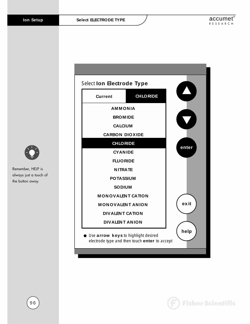
96
Ion Setup accumet®
R E S E A R C HSelect ELECTRODE TYPE
Remember, HELP is
always just a touch of
the button away.
Select Ion Electrode Type
exit
helpUse arrow keys to highlight desired electrode type and then touch enter to accept
enter
Current CHLORIDE
AMMONIA
BROMIDE
CALCIUM
CARBON DIOXIDE
CHLORIDE
CYANIDE
FLUORIDE
NITRATE
POTASSIUM
SODIUM
MONOVALENT CATION
MONOVALENT ANION
DIVALENT CATION
DIVALENT ANION
97
Ion Setupaccumet®
R E S E A R C HSelect ELECTRODE TYPE
This screen allows you to select the type of electrode that is specific foryour ion of interest. Your choice of electrode informs the meter whichdefault slope to use in the calculations made for electrode efficiency andsample concentration. Once you have selected an electrode, you will notbe required to enter the default slope numerically.
Note: The default slope value specific for the electrode that you chooseis a theoretical slope value that is used in the calculations to determinethe efficiency of your electrode. This slope value is not the slope valuethat is displayed in the data box of the measurement screen. You will still need to standardize the meter using ion standards to determine theactual efficiency of your electrode.
To Select Electrode Type
Access the Select Electrode Type screen from the Ion Setup screen. The current electrode type is displayed on the screen.
Use the arrow keys to highlight the electrode type specific for the Ion of interest.
Touch enter to accept the electrode type and return to the Ion Setupscreen.
OR
Touch exit to return to the Ion Setup screen, without making any changes.
1
2
3

98
Ion Setup accumet®
R E S E A R C H
To Set Isopotential Point
The Isopotential Point is the millivolt reading for an electrode at whichtemperature has no effect on the measurement. Ion selective electrodes,unlike pH electrodes, are not designed to achieve any particular isopotential point. If samples and standards are at different temperatureswhen performing ISE experiments, it will be necessary to experimentallydetermine the isopotential point of your Ion Specific Electrode. (seeAppendix: Determining Isopotential Point Experimentally page 137.)
The Ion Isopotential Point is set the same way as previously described in pH Setup. See page 62 for instructions.
To Set Alarm Limits
This option allows you to set alarm limits for the Ion measuring mode. If the ion concentration measurement is outside of the boundaries set bythe upper and lower limits, an audible alarm and/or a visual warningwill appear to let you know that your sample measurement was outsideof the set limits.
The Ion Alarm Limits are set the same way as previously described in pH Setup. See page 64 for instructions.
To Set Print Criteria
This screen allows you to select what criteria are printed with the measurement when you print the data or send it to a computer. The status of the current print criteria is displayed on the screen. The criteriaoption is active if “ON” appears to the right of the option. It is inactive if “OFF” appears to the right of the option. Any active criteria will beprinted on demand.
The Ion Print Criteria are set the same way as previously described inpH Setup. See page 66 for instructions.
99
Ion Setupaccumet®
R E S E A R C H
To Set Print Interval
You have three options for setting the print interval: manual printing, stable reading printing, and timed interval printing.
The Ion Print Interval is set the same way as previously described in pH Setup. See page 68 for instructions.
To Set Data Storage Criteria
This screen allows you to select what criteria are stored in the meter’smemory with the measurement when you save the data. The status of thecurrent data storage criteria is displayed on the screen. The criteriaoption is active if “ON” appears to the right of the option. It is inactive if “OFF” appears to the right of the option. Any active criteria will bestored with the measurement. All storage criteria will be stored in themeter’s memory with the measurement. However, only active items willappear on the View Stored Data screens. Changing the status of the storage criteria to active from inactive will allow the criteria to be displayed with the previously stored data.
The Ion Data Storage Criteria are set the same way as previouslydescribed in pH Setup. See page 70 for instructions.
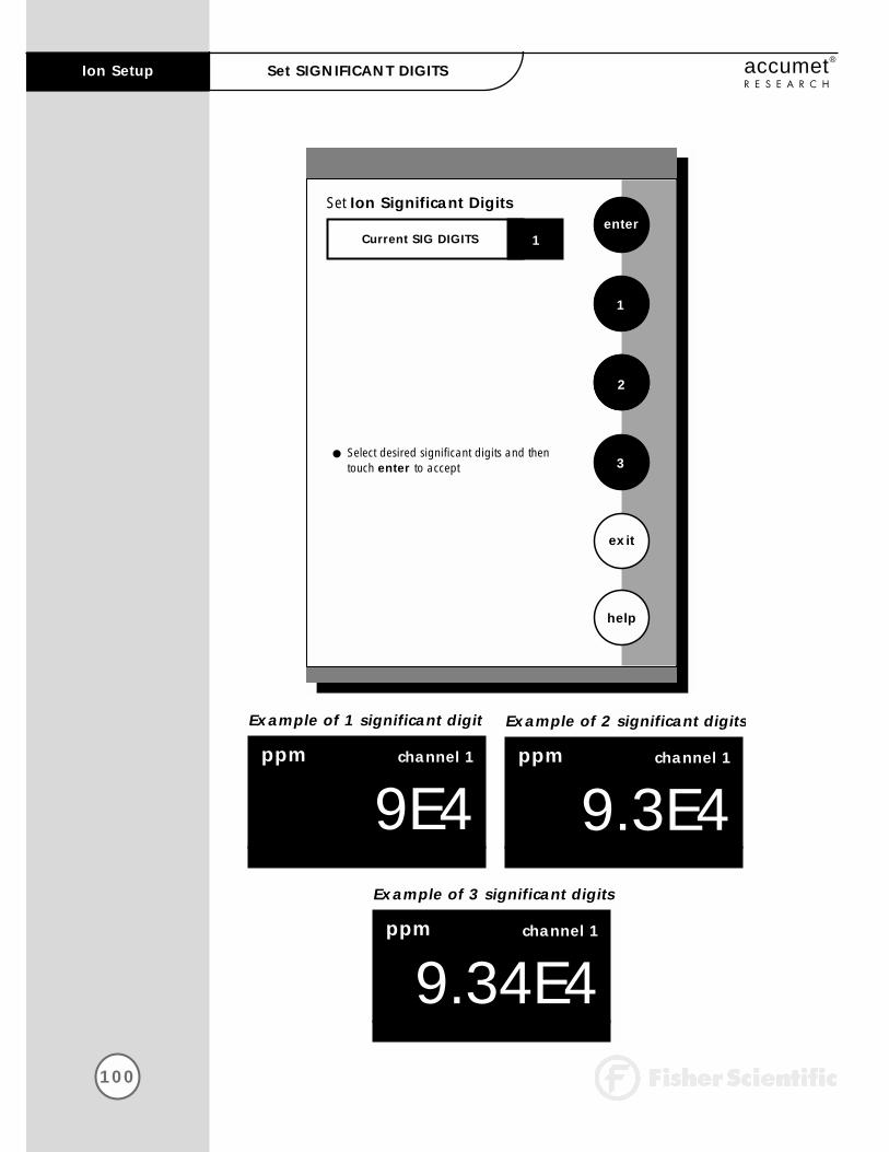
100
Ion Setup accumet®
R E S E A R C HSet SIGNIFICANT DIGITS
Set Ion Significant Digitsenter
exit
help
Select desired significant digits and then touch enter to accept
1
2
Current SIG DIGITS
3
1
Example of 1 significant digit
ppm channel 1
9E4
Example of 2 significant digits
ppm channel 1
9.3E4Example of 3 significant digits
ppm channel 1
9.34E4
101
Ion Setupaccumet®
R E S E A R C HSet SIGNIFICANT DIGITS
This option allows you to select the number of significant figures that willbe used when reporting your ion measurement. You have the choice ofone, two or three significant digits.
To Set significant digits
Access the Set Significant Digits screen from the Ion Setup screen. The current Significant digits are displayed on the screen.
Touch 1, 2, or 3 to select the desired significant digits.
Touch enter to accept the number of significant digits and return to the Ion Setup screen.
OR
Touch exit to return to the Ion Setup screen, without making any changes.
To Set Display Configuration
This function will allow you to choose what information you would like tobe displayed on the Ion Measure screen, particularly the informationcontained in the data box at the bottom of that screen.
The Ion Display Configuration is set the same way as previouslydescribed in pH Setup. See page 74 for instructions.
To View Stored Data
This meter has memory capacity for up to 250 data points. The ViewStored Data screen allows you to sort and look at specific data points.The stored data can be sorted by sample identification number, date or operator identification number.
The Ion Stored Data is viewed the same way as previously described in pH Setup. See page 76 for instructions.
1
2
3
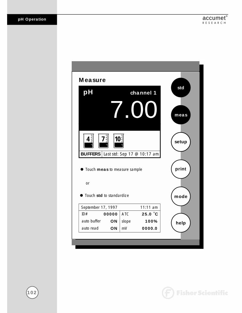
102
pH Operation accumet®
R E S E A R C H
Measure
07.00pH
std
meas
setup
mode
help
Touch meas to measure sample print
channel 1
Touch std to standardize
or
ATC
slope
mV
25.0 °C
100%
0000.0
September 17, 1997 11:11 amID#
auto buffer
auto read
00000
ON
ON
BUFFERS Last std: Sep 17 @ 10:17 am
4 7 10

103
pH Operationaccumet®
R E S E A R C H
In this mode, you will be able to measure the pH of a wide variety ofsamples. Before measuring pH, you will need to standardize the meterusing buffers with known pH values. It is good practice to standardizethe meter frequently using a minimum of two buffers. Using two buffersallows the meter to calculate and display an actual slope for the electrode, and therefore produce more accurate measurements. If thereis no standardization in the memory of the meter or if only one bufferhas been used to standardize the meter, the slope value will appear as“NA”.
You can standardize your meter using automatic or manual buffer recognition. With the Automatic buffer recognition activated, the meterwill automatically recognize the buffers from the chosen buffer groupand accept them when the meter recognizes the reading as stable.When in the Manual buffer recognition mode, you must enter the buffervalue during the standardization procedure. The meter will accept themanually entered buffer when it recognizes that the measurement is stable. During the standardization procedure, you may accept the buffer value before the meter recognizes it as stable by touching std.See page 56 to select desired buffer recognition.
At the Basic Procedural level the only setup options that you can accessare the Buffer Groups, the Print Interval and the Display Resolution. Ifyou need to change any other parameter such as Buffer Recognition orAuto Read mode you will need to set the Procedural Level to Advancedin the System Setup screen. Any values previously saved in the pH Setupscreen at the Advanced Procedural Level will become the default valuesfor the Basic Procedural Level.
Remember to setup your pH measuring mode parameters. Refer to pages44-79 for pH setup instructions.
Connect the electrodes you will be using to the meter. See page 10 for details.

104
pH Operation accumet®
R E S E A R C HStandardizing
Remember, HELP is
always just a touch of
the button away.
Standardize
07.00pH
std
meas
setup
mode
help
Insert electrode into buffer and stir
clear
channel 1
Touch std to standardize new buffer
ATC
slope
mV
25.0 °C
100%
0000.0
September 17, 1997 11:11 amID#
auto buffer
auto read
00000
ON
ON
BUFFERS Last std: Sep 17 @ 10:17 amCurrent BUFFER GROUP USA
4 7 10
Touch clear to delete previous buffers
Measure
07.00pH
std
meas
setup
mode
help
Touch meas to measure sample print
channel 1
Touch std to standardize
or
ATC
slope
mV
25.0 °C
100%
0000.0
September 17, 1997 11:11 amID#
auto buffer
auto read
00000
ON
ON
BUFFERS Last std: Sep 17 @ 10:17 am
4 7
STABLE

105
pH Operationaccumet®
R E S E A R C HStandardizing
For optimal results, the
meter should be standard-
ized at a minimum of
every 8 hours. For more
accurate measurements,
the meter should be stan-
dardized more frequently.
To Standardize the meter with Auto Buffer Recognition
Touch STD on the pH measure screen to access the standardize screen.
Touch clear to delete a previous standardization. All pH standardization values will be cleared. The meter will remain on the Standardization screen at this point.
OR
If the screen says “Not Standardized” proceed to step 3.
Immerse your rinsed electrode(s) in a buffer solution from the selectedbuffer group that you chose during the setup process (see pages 54)and stir gently.
Touch std again to standardize the meter using this buffer. The wordMEASURING will flash until the signal is stable. The meter will acceptthe value once it recognizes that the reading is stable. At that time,STABLE will appear on the screen. A beaker icon and the entered pHvalue will also appear on the screen at this time. The meter will thenreturn to the measure screen.
Touch std on the pH measure screen to access the standardizationscreen and repeat steps 3 through 5 to standardize with up to 5buffers.
Updating a standardization with Auto Buffer Recognition:
You can update a standardization at anytime. To update a standardization,place your electrode in any of the buffers originally used to standardize themeter and touch std on the touch screen twice. The value for that buffer will beupdated and stored in the meter’s memory. The time of standardization will alsobe updated on the pH measurement screen.
The efficiency of the electrode is reported as the slope. When doing a multi-pointstandardization, the slopes of the individual segments are calculated by themeter. The slope that appears on the screen is the slope that is the least perfect,or the farthest from 100%.
1
2
3
4
5

106
pH Operation accumet®
R E S E A R C HStandardizing
Standardize
07.00pH
std
meas
setup
mode
help
Insert electrode into buffer and stir
clear
channel 1
Touch std to standardize new buffer
ATC
slope
mV
25.0 °C
100%
0000.0
September 17, 1997 11:11 amID#
auto buffer
auto read
00000
ON
ON
BUFFERS Last std: Sep 17 @ 10:17 amCurrent BUFFER GROUP USA
4 7 10
Touch clear to delete previous buffers
Standardize
7.00pH
std
meas
setup
mode
help
Insert electrode into buffer and stir
clear
channel 1
Touch std to standardize new buffer
ATC
slope
mV
25.0 °C
NA
0000.0
September 17, 1997 11:11 amID#
auto buffer
auto read
00000
ON
ON
BUFFERS Not standardizedCurrent BUFFER GROUP USA
Touch clear to delete previous buffers
1 2 3
4 5 6
7 8 9
exit
Enter pH
BS enter
- 0 .
107
pH Operationaccumet®
R E S E A R C HStandardizing
To standardize the meter with manual buffer recognition
Touch std on the pH measure screen to access the standardize screen.
Touch clear to delete a previous standardization. All pH standardization values will be cleared. The meter will remain on the Standardization screen at this point.
OR
If the screen says “Not Standardized” proceed to step 3.
Immerse your rinsed electrode(s) in a buffer solution and stir gently.
Touch std again to standardize the meter using this buffer.
Using the displayed keypad, input the value of the buffer that you areusing to standardize the meter and then touch enter. The meter willaccept the value once it recognizes that the reading is stable. At thattime, STABLE will appear on the screen. A beaker icon and the entered pH value will also appear on the screen at this time. The meter will return to the pH measure screen.
Touch std on the pH measure screen to access the standardizationscreen and repeat steps 3 through 5 to standardize with up to 5buffers.
Updating a standardization with Manual Buffer Recognition:
You can update a standardization at any time. To update a standardization withmanual buffer recognition, place your electrode in any of the buffers originallyused to standardize the meter and touch the std key on the touch screen twice.Then using the keypad displayed on the screen enter the value of the buffer andtouch enter. The value for that buffer will be updated and stored in the meter’smemory. The time of standardization will also be updated on the pH measurescreen.
1
2
3
4
5
6
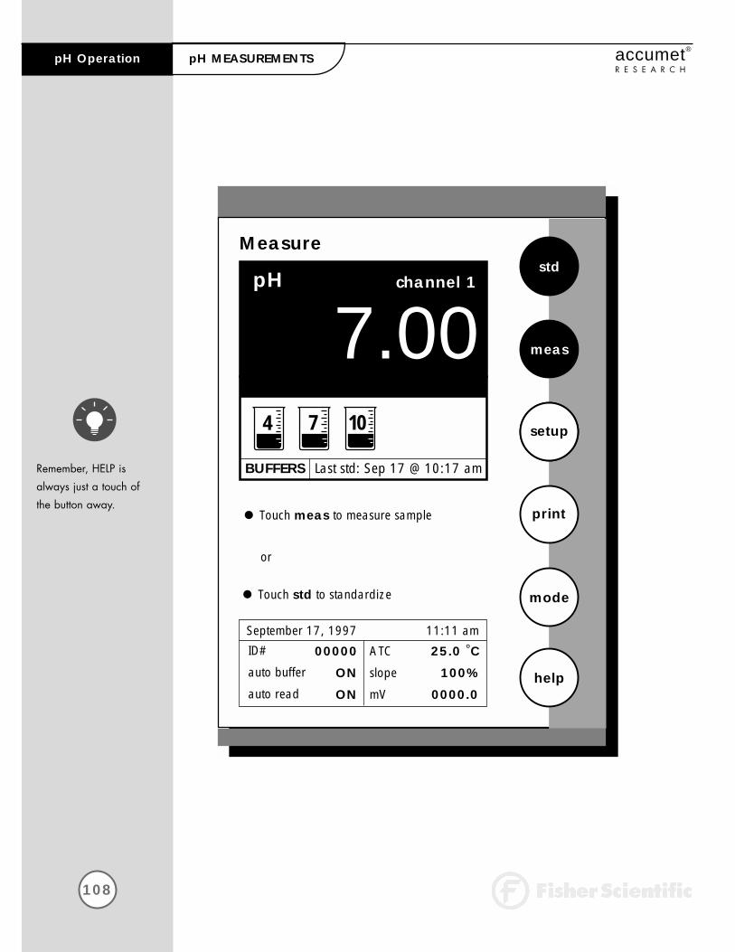
108
pH Operation accumet®
R E S E A R C HpH MEASUREMENTS
Remember, HELP is
always just a touch of
the button away.
Measure
07.00pH
std
meas
setup
mode
help
Touch meas to measure sample print
channel 1
Touch std to standardize
or
ATC
slope
mV
25.0 °C
100%
0000.0
September 17, 1997 11:11 amID#
auto buffer
auto read
00000
ON
ON
BUFFERS Last std: Sep 17 @ 10:17 am
4 7 10
109
pH Operationaccumet®
R E S E A R C HpH MEASUREMENTS
The measure screen provides a readout of the current sample measure-ment. You can use this meter when the Auto Read function is active orwhen it is inactive. When the Auto Read function is active, the meter willlock onto a reading when the meter recognizes it as stable. The meterwill not deviate from this reading until meas is touched. If the AutoRead mode is inactive, then the meter will continuously monitor the pH ofthe sample and the measure display screen will indicate any fluctuationin the sample pH. Regardless of the status of the Auto Read mode, STABLE will flash as the meter recognizes the measurement as stable.
Once the meter is standardized, you are ready to take pH measurementsof your sample.
To measure pH of a sample with Auto Read ON
Immerse the rinsed electrode(s) in the stirring sample.
Touch meas to begin measuring your sample. The meter will accept thereading and display STABLE when the measurement meets the selectedstability criteria.
OR
To measure pH of a sample with Auto Read OFF
Immerse the rinsed electrode(s) in the stirring sample.
Record the reading once the measurement has become stable. STABLEwill appear once the meter recognizes that the measurement is stable.
NOTES: You can access other functions of the meter with the remaining buttonson the measure screen. • Touching print will send the data to the meter’s memory if the sample ID#
is activated and to a printer or computer if it is attached to the meter. The saved data can be accessed through the View Stored Data screen in the pH Setup mode.
• Touching setup will access the pH Setup screen. For detailed informationregarding pH Setup see pages 44-79.
• Touching meas will initiate a new measurement of a sample.• At anytime, you can touch mode to access another mode of operation
including: mV, rel mV, Ion or the setup mode or place the meter in the standby mode.
1
2
1
2

110
mV Operation accumet®
R E S E A R C H
This mode is used to measure oxidation/reduction potential (ORP/redox),perform titration and to verify the function of the meter. The mV measurefunction allows you to continuously monitor the mV potential of the electrodes in use. This can be done in either absolute or relative mV. In the millivolt mode, the current millivolt output from the electrodes beingused is monitored and displayed on the screen. The meter will continuallymonitor the millivolt reading in this mode and will not lock onto a singlereading. However, once the reading has become stable, a stable message will be displayed. Remember to setup your mV measuring mode parameters. Refer to pages 80-87 for mV setup instructions.
Measure
00.0abs mV
REL
setup
mode
help
channel 1
Touch REL for Relative mV reading
ATC 25.0 °CSeptember 17, 1997 11:11 amID# 00000
111
mV Operationaccumet®
R E S E A R C HmV MEASUREMENT
Rinse the electrode with
water and blot dry. Do
not wipe the electrode.
Wiping the electrode can
cause a static charge on
the glass bulb that will
result in inaccurate
readings.
In the mV mode, you will be able to make measurements in eitherabsolute or relative millivolts, access the mV Setup screens and print your results to a printer or a computer.
Connect the electrodes you will be using to the meter. See page 10 for details.
Absolute mV measurements
Access the mV Measure screen from the main screen.
Touch ABS to access the Absolute mV screen.
Immerse your rinsed electrode(s) in the sample and stir gently.
Record the measurement when STABLE is displayed.
Touch print to store a measurement with an assigned ID# in thedata storage center of the meter or print the data to a printer or computer.
Relative mV measurements
In this mode, the first mV reading is set to zero and all subsequent readings arerelative to this initial mV measurement.
Access the mV Measure screen from the main screen.
Touch REL to access the Relative mV screen.
Immerse your rinsed electrode(s) in the stirring sample.
Record the measurement when STABLE is displayed.
Touch print to store a measurement with an assigned ID# in the datastorage center of the meter or print the data on a printer or computer.
1
2
3
4
5
1
2
3
4
5
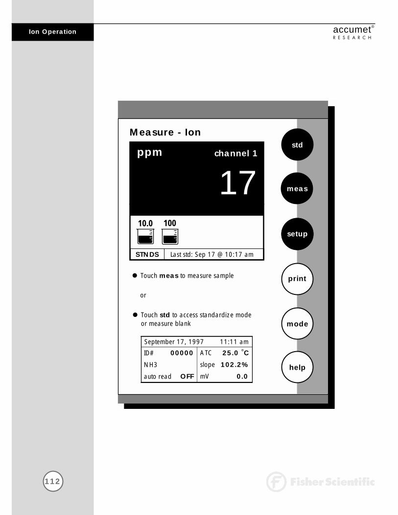
112
Ion Operation accumet®
R E S E A R C H
Measure - Ion
ppm
STABLE
std
setup
mode
help
ATC
slope
mV
25.0 °C
102.2%
0.0
September 17, 1997 11:11 am
or
channel 1
Touch meas to measure sample
ID#
NH3
auto read
00000
OFF
17
STNDS Last std: Sep 17 @ 10:17 am
10.0 100
Touch std to access standardize modeor measure blank
meas
113
Ion Operationaccumet®
R E S E A R C H
Remember to setup your
Ion measuring mode
parameters. Refer to
pages 88-101 for Ion
setup instructions.
The accumet AR50 meter offes you unparalleled versatility with respect toion analysis. You can choose one of 6 methods of analysis, the specificelectrode you will be working with and also the units that you would likethe meter to use when reporting the ion concentration. The Ion Measurescreen displays the direct readout of sample concentration in the desiredunits, as well as the time and date of the last calibration. The standardsused in the calibration and the slope of the electrode are also displayedon the screen. It is important to note that the concentration reported bythe meter is actually the concentration of free uncomplexed ions in your solution.
At the Basic Procedural level the only setup options that you can accessare the Electrode Type, the Print Interval and the number of SignificantDigits. If you need to change any other parameter such as Ion method ormeasurement units you will need to set the Procedural Level to Advancedin the System Setup screen. Any values previously saved in the Ion Setupscreen at the Advanced Procedural Level will become the default valuesfor the Basic Procedural Level.
Connect the electrodes you will be using to the meter. See page 10 for details.
Remember, HELP is
always just a touch of
the button away.

114
Ion Operation accumet®
R E S E A R C HDIRECT READING METHODS
Standardize - Ion
ppm
STABLE
std
setup
mode
help
ATC
slope
mV
25.0 °C
100.2%
0.0
September 17, 1997 11:11 am
Insert electrode into standard and stir
clear
channel 1
Touch clear to delete previous standards
ID#
NH3
auto read
00000
OFF
- - -
STNDS Last std: Sep 17 @ 10:17 am
10.0 100
Touch std to standardize new standard
meas
Standardize - Ion
ppm
STABLE
std
setup
mode
help
ATC
slope
mV
25.0 °C
NA
0.0
September 17, 1997 11:11 am
Insert electrode into standard and stir
clear
channel 1
ID#
NH3
auto read
00000
OFF
- - -
STNDS Not standardized
Touch std to standardize new standard
meas
Standardize - Ion
ppm
STABLE
std
setup
mode
help
ATC
slope
mV
25.0 °C
NA
0.0
September 17, 1997 11:11 am
Insert electrode into standard and stir
clear
channel 1
ID#
NH3
auto read
00000
OFF
- - -
STNDS Not standardized
Touch std to standardize new standard
meas
1 2 3
4 5 6
7 8 9
exit
Concentration
BS enter
- 0 .

115
Ion Operationaccumet®
R E S E A R C HDIRECT READING METHODS
There are two direct reading methods: Direct Reading with standardsand Direct Reading with Blank offset. These types of measurements allowyou to directly read the concentration of your sample after standardizingthe meter with ion standards of known values or blank values.
Direct Reading with Standards
This is the most common method of ion measurement. You can directly read theconcentration of the sample after standardizing the meter with ion standards. An ionic strength adjuster (ISA) is added to both the standards and the sample.Two to five standards are used to standardize the meter. The standards shouldbracket the expected value of the sample.
To Standardize the Meter
You must use a minimum of two standards to standardize the meter.
Touch std on the Ion Measure screen to access the standardizationscreen.
Touch clear to remove a previous standardization.
Add ionic strength adjuster to your standard.
Immerse the ion selective electrode and the appropriate reference electrode (or combination ISE) into the standard containing the lowest concentration of the ion of interest. Stir.
Touch std again to initiate the standardization process.
Use the numeric keypad to enter the value of the standard.
Touch enter on the keypad to accept this value. If you have entered a value in error, touch BS to clear the value and key in a new value.
OR
Touch exit to return to the Ion Measure screen without entering a standard value.
Repeat steps 3-7 with up to 5 standards. A minimum of two standards is required to standardize the meter in this mode.
1
2
3
4
5
6
7
8
Generally, it is important
that an ionic strength
adjuster (ISA) is added
to both samples and
standards to obtain
accurate results.
If the meter has not been
standardized with at
least 2 standards, a
series of dashes will
appear in place of a
measurement value.

116
Ion Operation accumet®
R E S E A R C HDIRECT READING METHODS
Measuring ion concentration in the Direct Reading with Standards Mode
With Auto Read on
Add Ionic strength adjuster to the sample.
Immerse the ion selective electrode in the stirring sample.
Touch meas to begin measuring your sample. The meter will accept the reading and display STABLE when the measurement meets the selected stability criteria. The measure screen will fix onto this measurement and will not deviate until meas is touched.
Repeat steps 1-3 with additional samples.
With Auto Read off
Add Ionic strength adjuster to the sample.
Immerse the ion selective electrode into the stirring sample. The meterwill continually monitor the ion concentration value. When the meterrecognizes the reading as stable, STABLE is displayed on the measurescreen. With the Auto Read function deactivated, the display on themeasure screen will indicate any deviation in the concentration.
Repeat steps 1-2 with additional samples.
1
2
3
4
1
2
3
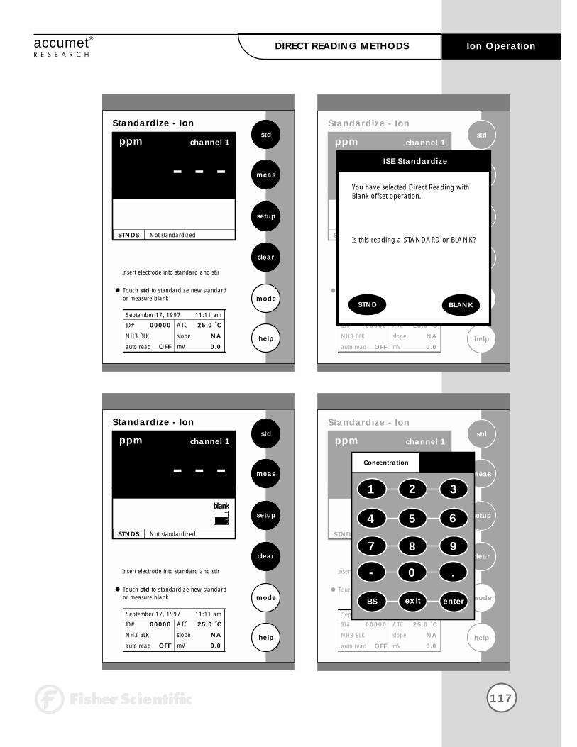
117
Ion Operationaccumet®
R E S E A R C HDIRECT READING METHODS
Standardize - Ion
ppm
STABLE
std
setup
mode
help
ATC
slope
mV
25.0 °C
NA
0.0
September 17, 1997 11:11 am
Insert electrode into standard and stir
clear
channel 1
ID#
NH3 BLK
auto read
00000
OFF
- - -
STNDS Not standardized
Touch std to standardize new standard
meas
You have selected Direct Reading with Blank offset operation.
Is this reading a STANDARD or BLANK?
ISE Standardize
BLANKSTND
Standardize - Ion
ppm
STABLE
std
setup
mode
help
ATC
slope
mV
25.0 °C
NA
0.0
September 17, 1997 11:11 am
Insert electrode into standard and stir
clear
channel 1
ID#
NH3 BLK
auto read
00000
OFF
- - -
STNDS Not standardized
Touch std to standardize new standardor measure blank
meas
Standardize - Ion
ppm
STABLE
std
setup
mode
help
ATC
slope
mV
25.0 °C
NA
0.0
September 17, 1997 11:11 am
Insert electrode into standard and stir
clear
channel 1
ID#
NH3 BLK
auto read
00000
OFF
- - -
STNDS Not standardized
Touch std to standardize new standardor measure blank
meas
blank
Standardize - Ion
ppm
STABLE
std
setup
mode
help
ATC
slope
mV
25.0 °C
NA
0.0
September 17, 1997 11:11 am
Insert electrode into standard and stir
clear
channel 1
ID#
NH3 BLK
auto read
00000
OFF
- - -
STNDS Not standardized
Touch std to standardize new standard
meas
1 2 3
4 5 6
7 8 9
exit
Concentration
BS enter
- 0 .

118
Ion Operation accumet®
R E S E A R C H
Direct Reading with Blank Offset
This method presents you with the ability to measure samples with lowlevel concentrations of the ion of interest. It eliminates backgroundinterference by subtracting the value of a blank concentration from the value for the sample. See ISE Theory page 146.
To Standardize the Meter
You will need to standardize the meter with one blank and a minimum of twostandards.
Touch STD on the Ion Measure screen to access the standardize screen.
Touch clear to delete the previous standards.
Add ionic strength adjuster to the standards and the blank.
Immerse the ion selective electrode in the standard containing the lowest concentration of the ion of interest.
Stir the standard and/or blank.
Touch STD again to initiate the standardization process. At this point,the meter will display the question “Is this a standard or a blank?”
Touch STND if the sample that the electrode is immersed in is an Ionstandard solution.
OR
Touch BLANK if the sample that the electrode is immersed in is theblank solution.
1
2
3
4
5
6
7
DIRECT READING METHODS
Remember, HELP is
always just a touch of
the button away.

If you touched STND
Use the keypad to enter the value of the standard.
Touch enter to accept the value. The meter will accept the standardvalue when it recognizes the reading as stable.
Repeat steps 4-7 with additional standards or steps 4-7 and 11 with a blank sample.
If you touched BLANK
The meter will return to the Ion Measure screen and a beaker iconlabeled blank will be displayed.
Repeat steps 4-9 if the meter has not been standardized with at least 2standards of known ion concentration.
119
Ion Operationaccumet®
R E S E A R C HDIRECT READING METHODS
11
89
10
Measuring Ion Concentration in the Direct Reading withBlank Mode
With Auto Read on
Add ionic strength adjuster to the samples.
Immerse the ion selective electrode in the stirring sample
Touch meas. When the meter recognizes the reading as stable, STABLE will appear on the screen. The value that appears on thescreen is the value of the sample minus the value of the blank reading.The measure screen will fix on this measurement and will not deviateuntil meas is touched again.
Repeat steps 1-3 with additional samples. The meter will update thereading each time meas is touched.
With Auto Read off
Add ionic strength adjuster to the sample.
Immerse the ion selective electrode in the stirring sample. The meter will continually monitor the ion concentration value. When the meter recognizes the reading as stable, STABLE is displayed on the measure screen. With the Auto Read function deactivated, the display on the measure screen will indicate any deviation in the concentration reading.
1
23
4
1
2

120
Ion Operation accumet®
R E S E A R C HINCREMENTAL METHODS
Standardize - Ion
ppm
STABLE
std
setup
mode
help
ATC
slope
mV
25.0 °C
100.2%
0.0
September 17, 1997 11:11 am
Insert electrode into standard and stir
clear
channel 1
Touch clear to delete previous standards
ID#
NH3 IM
auto read
00000
OFF
- - -
STNDS Last std: Sep 17 @ 10:17 am
10.0 100
Touch std to standardize new standard
meas
Standardize - Ion
ppm
STABLE
std
setup
mode
help
ATC
slope
mV
25.0 °C
NA
0.0
September 17, 1997 11:11 am
Insert electrode into standard and stir
clear
channel 1
ID#
NH3 IM
auto read
00000
OFF
- - -
STNDS Not standardized
Touch std to standardize new standard
meas
Standardize - Ion
ppm
STABLE
std
setup
mode
help
ATC
slope
mV
25.0 °C
NA
0.0
September 17, 1997 11:11 am
Insert electrode into standard and stir
clear
channel 1
ID#
NH3 IM
auto read
00000
OFF
- - -
STNDS Not standardized
Touch std to standardize new standard
meas
1 2 3
4 5 6
7 8 9
exit
Concentration
BS enter
- 0 .

121
Ion Operationaccumet®
R E S E A R C HINCREMENTAL METHODS
The incremental methods which include known addition, known subtraction, analate addition and analate subtraction and are particularly useful with samples containing complex ionic backgroundswhich cannot be matched in standards. They are also useful with occasional samples whose temperatures vary. More information on these methods is available in the ISE Theory Section (see page 146).
Standardizing the meter for all incremental methods
Prior to conducting an analysis using any of the incremental methods, itis necessary to standardize the meter with at least two standards. Thiswill establish a slope value for the electrode in use. The slope value isrequired in the incremental method calculations which yield the ion concentration of the sample. See ISE Theory page 146.
Touch std on the Ion Measure screen to access the standardize screen.
Touch clear to remove the previous standardization from the memory ofthe meter.
Add ionic strength adjuster to the standards.
Immerse the ion selective electrode in the stirring standard. Alwaysbegin standardization with the least concentrated ion standard.
Touch std again to initiate standardization.
Use the keypad to enter value of the standard.
Touch enter on the keypad to accept this value. If you have entered a value in error, touch BS to clear the value and key in a new value.
Repeat steps 3-7 with additional standards.
1
2
3
4
5
6
7
8
Remember, HELP is
always just a touch of
the button away.

122
Ion Operation accumet®
R E S E A R C HKNOWN ADDITION METHOD
Measure - Ion
mV
STABLE
std
setup
mode
help
ATC
slope
mV
25.0 °C
102.2%
0.0
September 17, 1997 11:11 am
channel 1
ID#
NH3 KA
auto read
00000
OFF
0.0
STNDS Last std: Sep 17 @ 10:17 am
10.0 100
Touch std to access standardize mode
KA
1.00
Measure - Ion
mV
STABLE
std
setup
mode
help
ATC
slope
mV
25.0 °C
102.2%
0.0
September 17, 1997 11:11 am
Insert electrode into standard and stir
channel 1
ID#
NH3 KA
auto read
00000
OFF
0.0
STNDS Not Standardized
Touch std to standardize new standard
KA
Measure - Ion
mV
STABLE
std
setup
mode
help
ATC
slope
mV
25.0 °C
NA
0.0
September 17, 1997 11:11 am
Insert electrode into standard and stir
clear
channel 1
ID#
NH3 KA
auto read
00000
OFF
- - -
STNDS Not standardized
Touch std to standardize new standard
meas
1 2 3
4 5 6
7 8 9
exit
Sample Volume
BS enter
- 0 .
Measure - Ion
mV
STABLE
std
setup
mode
help
ATC
slope
mV
25.0 °C
NA
0.0
September 17, 1997 11:11 am
Insert electrode into standard and stir
clear
channel 1
ID#
NH3 KA
auto read
00000
OFF
- - -
STNDS Not standardized
Touch std to standardize new standard
meas
1 2 3
4 5 6
7 8 9
exit
Standard Volume
BS enter
- 0 .
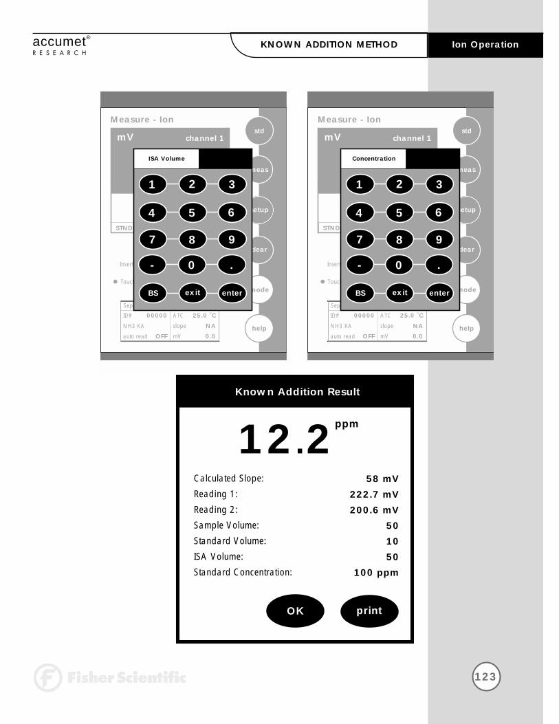
123
Ion Operationaccumet®
R E S E A R C HKNOWN ADDITION METHOD
Measure - Ion
mV
STABLE
std
setup
mode
help
ATC
slope
mV
25.0 °C
NA
0.0
September 17, 1997 11:11 am
Insert electrode into standard and stir
clear
channel 1
ID#
NH3 KA
auto read
00000
OFF
- - -
STNDS Not standardized
Touch std to standardize new standard
meas
1 2 3
4 5 6
7 8 9
exit
ISA Volume
BS enter
- 0 .
Measure - Ion
mV
STABLE
std
setup
mode
help
ATC
slope
mV
25.0 °C
NA
0.0
September 17, 1997 11:11 am
Insert electrode into standard and stir
clear
channel 1
ID#
NH3 KA
auto read
00000
OFF
- - -
STNDS Not standardized
Touch std to standardize new standard
meas
1 2 3
4 5 6
7 8 9
exit
Concentration
BS enter
- 0 .
12.2ppm
Known Addition Result
OK print
Calculated Slope:
Reading 1:
Reading 2:
Sample Volume:
Standard Volume:
ISA Volume:
Standard Concentration:
58 mV222.7 mV200.6 mV
501050
100 ppm

124
Ion Operation accumet®
R E S E A R C HKNOWN ADDITION METHOD
Measuring Ion Concentration in Samples Using theIncremental Methods
When performing known addition, you will add an aliquot of standardsolution containing the ionic species of interest to a known volume ofyour sample. The mV readings of the sample are taken before and afterthe addition of the standard. The concentration of the sample can thenbe calculated based upon the difference in the mV readings. The use ofthe incremental methods requires that certain parameters be identified. Inaddition to the millivolt outputs of the electrode(s) in both the sample andthe sample plus the standard, it is necessary to enter into the meter thevolume of the sample, the volume of the standard, the volume of theIonic Strength Adjuster (ISA) if used, the concentration of the standardand as previously stated the slope of the electrode in use. Your accumetresearch meter will prompt you through the method, permitting you toenter the appropriate parameters at the appropriate time. When themeter has all of the data needed for the calculation, it will display theion concentration of the sample as well as the parameters entered for thecalculation.
The standard concentration should be high enough to nearly double the sample ion concentration after its addition. However, the standardvolume should not significantly impact the sample volume. A 1:100 ratioof standard to sample ratio is optimal. For a monovalent electrode, thestandard addition should result in a 15-30 mV change. For a divalentelectrode, a 7-10 mV change is adequate. If the millivolt change is toohigh, the addition of the standard may affect the ionic strength andtherefore the activity coefficients. This could result in inaccurate measurements. If the millivolt change is too small, readability errorsare enhanced. See ISE Theory page 146.
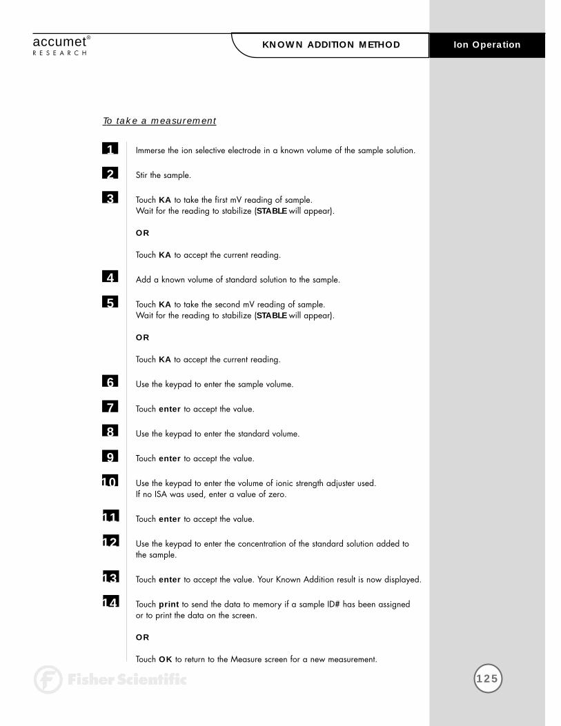
125
Ion Operationaccumet®
R E S E A R C HKNOWN ADDITION METHOD
To take a measurement
Immerse the ion selective electrode in a known volume of the sample solution.
Stir the sample.
Touch KA to take the first mV reading of sample. Wait for the reading to stabilize (STABLE will appear).
OR
Touch KA to accept the current reading.
Add a known volume of standard solution to the sample.
Touch KA to take the second mV reading of sample. Wait for the reading to stabilize (STABLE will appear).
OR
Touch KA to accept the current reading.
Use the keypad to enter the sample volume.
Touch enter to accept the value.
Use the keypad to enter the standard volume.
Touch enter to accept the value.
Use the keypad to enter the volume of ionic strength adjuster used. If no ISA was used, enter a value of zero.
Touch enter to accept the value.
Use the keypad to enter the concentration of the standard solution added tothe sample.
Touch enter to accept the value. Your Known Addition result is now displayed.
Touch print to send the data to memory if a sample ID# has been assigned or to print the data on the screen.
OR
Touch OK to return to the Measure screen for a new measurement.
1
2
3
4
5
6
7
8
9
10
11
12
13
14

126
Ion Operation accumet®
R E S E A R C HKNOWN SUBTRACTION METHOD
The procedure for known subtraction is very similar to that for knownaddition method. An aliquot of standard is added to a known volume of the sample. The difference is that the standard does not contain thesame ionic species that you are trying to measure in the sample. Instead,it contains an ion that will complex or precipitate the ion of interest,removing it from the sample. Like known addition, the mV readings aretaken before and after the standard is added to the sample and the difference in mV values can be used to calculate the concentration offree ions of interest in the sample. This method will also require you toenter values of certain parameters in order to obtain an ion concentra-tion. See ISE Theory page 146.
To take a measurement
Immerse the ion selective electrode in a known volume of the sample solution.
Stir the sample.
Touch KS to take the first reading. Wait for the reading to stabilize (STABLE will appear).
OR
Touch KS to accept the current reading.
Add a known volume of standard solution to the sample.
Touch KS to take the second reading. Wait for the reading to stabilize (STABLE will appear).
OR
Touch KS to accept the current reading.
Use the keypad to enter the sample volume.
Touch enter to accept the value.
Use the keypad to enter the standard volume.
Touch enter to accept the value
1
2
3
4
5
6
7
8
9
Remember, HELP is
always just a touch of
the button away.
127
Ion Operationaccumet®
R E S E A R C HKNOWN SUBTRACTION METHOD
Use the keypad to enter the volume of ionic strength adjuster used. If no ISA was used, enter a value of zero.
Touch enter to accept the value.
Use the keypad to enter the concentration of the standard solutionadded to the sample.
Touch enter to accept the value. Your Known Subtraction result is now displayed.
Touch print to send the data to memory or to print the information on the screen.
OR
Touch OK to return to the Measure screen for a new measurement.
10
11
12
13
14

128
Ion Operation accumet®
R E S E A R C H
The analate addition method is useful when your sample is at an elevated temperature and you want to negate the effect that temperaturewill have on the concentration calculation. This method is also useful if you have only a small amount of sample available. The analate addition method differs only slightly from the known addition method.The difference being the solution that you are taking your initial mV reading in is actually the standard and not the sample of interest. The difference in mV readings of the standard before and after the sample isadded is used to calculate the concentration of the ion of interest. Withthe analate addition method, both the sample and the standard solutioncontain the ionic species of interest. See ISE Theory page 146.
To take a measurement
Immerse the ion selective electrode in a known volume of the standard solution.
Stir the standard.
Touch AA to take the first reading.Wait for the reading to stabilize (STABLE will appear).
OR
Touch AA to accept the current reading.
Add a known volume of sample solution to the standard solution
Touch AA to take the second reading. Wait for the reading to stabilize (STABLE will appear).
OR
Touch AA to accept the current reading.
Use the keypad to enter the sample volume.
Touch enter to accept the value.
Use the keypad to enter the standard volume.
Touch enter to accept the value.
1
2
3
4
5
6
7
8
9
Remember, HELP is
always just a touch of
the button away.
ANALATE ADDITION

129
Ion Operationaccumet®
R E S E A R C HANALATE ADDITION
Use the keypad to enter the volume of ionic strength adjuster used. If no ISA was used, enter a value of zero.
Touch enter to accept the value.
Use the keypad to enter the concentration of the standard solution.
Touch enter to accept the value. Your Analate Addition result is now displayed.
Touch print to send the data to memory or send the information to a printer.
OR
Touch OK to return to the Measure screen for a new measurement.
11
12
13
14
10

130
Ion Operation accumet®
R E S E A R C H
The analate subtraction method is useful when no ion specific electrode isavailable to measure the ion of interest directly. Like known subtractionthe sample and the standard contain different ionic species. However, the ion being measured is in the standard and not in the sample. Thereduction of free ions in the standard solution is proportional to theconcentration of the ion of interest in the sample. See ISE Theory page 146.
To take a measurement
Immerse the ion selective electrode in a known volume of the standard solution.
Stir the standard.
Touch AS to take the first reading.Wait for the reading to stabilize (STABLE will appear).
OR
Touch AS to accept the current reading.
Add a known volume of sample solution to the standard.
Touch AS to take the second reading.Wait for the reading to stabilize (STABLE will appear).
OR
Touch AS to accept the current reading.
Use the keypad to enter the sample volume.
Touch enter to accept the value.
Use the keypad to enter the standard volume.
Touch enter to accept the value.
1
2
3
4
5
6
7
8
9
Remember, HELP is
always just a touch of
the button away.
ANALATE SUBTRACTION

131
Ion Operationaccumet®
R E S E A R C HANALATE SUBTRACTION
10 Use the keypad to enter the volume of ionic strength adjuster used. If no ISA was used, enter a value of zero.
Touch enter to accept the value.
Use the keypad to enter the concentration of the standard solution.
Touch enter to accept the value. Your Analate Subtraction result is now displayed.
Touch print to send the data to memory or send the information to a printer or computer.
OR
Touch OK to return to the Measure screen for a new measurement.
11
12
13
14
132
Cleaning accumet®
R E S E A R C H
The touch screen should be kept as clean as possible to preserve opticalproperties. Attempt to keep the screen free of dirt, dust fingerprints, etc.Long term contact with abrasive materials will scratch the surface, andimpair image quality. To clean, use a damp nonabrasive cloth towel andany commercially available window cleaner. The cleaning solutionshould be applied to the towel rather than the surface of the touchscreen.
The case is made out of durable ABS plastic. It can be cleaned with a damp cloth and a mild detergent. Do not use chemical solvents on the case.
133
Trouble Shootingaccumet®
R E S E A R C H
Your AR meter contains many error messages to provide aid should trouble occur with a measurement or meter operation (touchpad andinput errors). The messages are accompanied by a brief description ofthe error, and in some cases advice on how to correct it. An example ofan error message is:
Bad Electrode Slope-The electrode you have standardized has a slopewhich is out of the normally acceptable range of 90% to 102%. You should try to restandardize, or replace your electrode if the problempersists. Note that you can continue to make measurements with thiselectrode; however, the readings may be inaccurate.
Other error messages delivered by the meter are:
Data log fullData log emptyUnrecognized dateUnrecognized timeInvalid pH limitInvalid Ion limitInvalid limitLimit exceededChannel 1 limit exceededChannel 2 limit exceededInvalid TemperatureInvalid IsopotentialInvalid Print IntervalInvalid pH valueSample ID not foundOperator not found
Also, whenever possible, touch help for complete information about themeter operation in which you are currently engaged.

134
Warranty accumet®
R E S E A R C H
pH Meter and Electrode Warranty Statement
The Fisher Scientific Company (“Fisher”) warrants to the direct purchaserthat the accumet meters and Accumet, AccuTupH, AccuFET, AccupHast,and Microprobe electrodes will be free from defects in material or workmanship for a specified warranty period. During that period, Fisherwill repair or replace the product or provide credit, at its sole option,upon prompt notification and compliance with its instructions. For accumet meters, that specified period is 24 months from delivery date.For electrodes, that specified period is 12 months - except for models 13-620-532, 13-620-533, 13-620-534, 13-620-535, 13-620-536, 13-620-537, 13-620-538 and 13-620-539 - which are warranted for six months.
Unless otherwise agreed, the warranty is limited to the country in whichthe product is sold.
No Fisher employee, agent or representative has the authority to bindFisher to any oral representation or warranty concerning any productsold. Any oral representation or warranty made prior to purchase of anyproduct and not set forth in writing and signed by a duly authorized offi-cer of Fisher shall not be enforceable by the purchaser.
FISHER EXPRESSLY DISCLAIMS ALL OTHER WARRANTIES, EXPRESS ORIMPLIED, INCLUDING THE IMPLIED WARRANTY OF MERCHANTABILITYAND FITNESS FOR A PARTICULAR PURPOSE.
Fisher’s sole responsibility and the purchaser’s exclusive remedy for anyclaim arising out of the purchase of any product listed above is repair,replacement or credit as described above, where applicable. In no event:1) shall the cost of the exclusive remedy exceed the purchase price: 2) shall Fisher be liable for any special, indirect, incidental, consequen-tial, or exemplary damages, howsoever arising, even if Fisher has beenadvised of the possibility of such damages.
Each article that Fisher furnishes will conform to the written specificationsgiven in this manual, or those of a further improved model. Changes aremade often to the information in the manual and will be incorporatedinto future editions.

Notice of Compliance
WARNING: This meter generates, uses, and can radiate radio frequencyenergy. If not installed and used properly, that is in strict accordance withthe manufacturer’s instructions, it may cause interference to radio communi-cations. It has been tested and found to comply with the limits for a Class Acomputing device pursuant to Subpart J of Part 15 of FCC Rules, which aredesigned to provide reasonable protection against such interference whenoperated in a commercial environment. Operation of this equipment in aresidential area may cause interference, in which case the user, at his ownexpense, will be required to take whatever measures may be required tocorrect the interference.
This product is to be used only as described in the manual. This product isfor indoor use only, and must be used in a well ventilated area.
WARNING: To meet or exceed FCC regulations and comply with CE requirements, the Fisher-supplied
power supply must be used. Use of a power supply that is notapproved by Fisher Scientific may cause safety hazardsand/or cause unit to exceed EMC limits and/or damage unit.When using this meter with a computer or printer, a shieldedRS232 cable must be used to meet or exceed FCC regulations,and comply with CE Mark requirements.
135
Complianceaccumet®
R E S E A R C H

136
Appendix accumet®
R E S E A R C HTABLE OF CONTENTS
Determining Isopotential Points Experimentally
Data Management
Factory Default Settings
pH Theory
ISE Theory
137
138
139
141
146

137
Appendixaccumet®
R E S E A R C HDetermining ISOPOTENTIAL POINTS EXPERIMENTALLY
The isopotential point of an electrode system is the point at which electrode potential is unaffected by a change in temperature. The coordinates of this point would be reported as (pXiso, Eiso). For an ideal system, this point would be coincident with the system’s Zero Potential Point (pXiso, E0).
In practical systems, however, this coincidence rarely occurs, and for somesystems, there is no true Isopotential Point but a general Isopotential area.If a system exhibits an apparent Isopotential Point, or at least anIsopotential area with relatively small spread, Isopotential coordinates maybe established and possibly used to some advantage. Isopotential correction may be used only in conjunction with a One- orTwo- Point Standardization; it is required only when both accuracy over asignificant temperature range as well as operation with an asymmetricelectrode system are contemplated. However, Isopotential correction isnever necessary if all measurements will be performed on samples whichare at similar temperatures. Most conventional pH electrode systems aredesigned and manufactured to be highly symmetrical cells. Consequently,for most pH work, unless ultimate accuracy over broad temperature rangesis required, Isopotential may be ignored. Specifically, this is accom-plished by setting the Isopotential at its reset value of zero millivolts.
The following is an example for determining an Isopotential Point:
Data points are first established for three different standards at three different temperatures. The data points are then plotted and will producethree isotherms which should resemble the plot in either figure 1 or figure 2. In figure 1, the Isopotential Point is well defined as the millivolt difference between the coincidence point of the three Isotherms (pXiso, Eiso) and the Zero Potential Point (E0). The Isopotential Point is not so well defined in figure 2, but a value may be interpolated with some accepted error.
Figure 1 Figure 2
138
Appendix accumet®
R E S E A R C HData MANAGEMENT
Your accumet pH meter is equipped with an RS-232 output port for sending measurement readings to a printer or computer. To use the meterwith a printer or computer, the printer or computer must have an RS-232port, also. It should be capable of receiving data within the followingguidelines.
Baud rates 110 to 38,400 BPSData bits 7 or 8Parity even, odd, or noneStop Bits 1 or 2
The meter and the output device must be configured to match withrespect to these parameters.
A shielded RS-232 cable must be used. The RS-232 connector is on theback of the meter. (see diagram page 8) The connector is a FemaleDB9 style connector. If the output device has a 25-pin connector, anadapter is required. If the meter and the printer or computer are to work together, the pin configurations must match. The meter’s 9-pin configuration is as follows.
Pin Description1 Buffers analog copy of pH input 12 Send data from meter3 Receive data to meter5 Signal Common9 Signal Common
To initiate printing, touch print if in the manual print mod, or set theprint interval for stable readings or at a prescribed timed interval. Referto the setup sections, Set Print Interval and Set Print Criteria.
To download data stored in memory to a printer or computer, access theView Stored Data option in the setup screens. Access the desired datapoint by sorting the data by one of the three options. Touch print on thescreen displaying the data

139
Appendixaccumet®
R E S E A R C H
The following is the list of factory default settings for the accumet AR50 meter. You can reset your meter to the factory default settings by accessing the Reset to Factory Defaults screen from the System Setup screen.
Mode Screen Default Setting
System Setup Time 12 hour time modeDate month/day/yearPrint Configuration Baud rate 19200
Parity noneData bits 8Stop bits 1
Procedural Level AdvancedOperator ID noneBeeper Status ONDisplay Contrast 15
pH Setup Display Configuration All parameters ONPrint Configuration All parameters ONData Configuration All parameters ONBuffer Group USASample ID# noneIsopotential Point 0 mVPrint Interval manualDisplay Resolution X.XXAuto Buffer Recognition ONAuto Read Mode OFFTemperature Units CelsiusDefault temperature 25.0°CStability Criteria MediumDefault slope 59.16 mVAlarm limits OFFAlarm limit low 0.000Alarm limit high 14.000
mV Setup Display Configuration All parameters ONPrint Configuration All parameters ONData Configuration All parameters ONSample ID# nonePrint Interval manualDisplay Resolution X.XmV readings Absolute mVAlarm limits OFFAlarm limit low -1800.0Alarm limit high 1800.0
Factory DEFAULT SETTINGS

140
Appendix accumet®
R E S E A R C HFactory DEFAULT SETTINGS
Mode Screen Default Setting
Ion Display Configuration All parameters ONPrint Configuration All parameters ONData Configuration All parameters ONSample ID# noneIsopotential Point 0 mVPrint Interval manualDisplay Resolution 2 Significant digitsAuto Read Mode OFFTemperature Units CelsiusDefault temperature 25.0°CStability Criteria mediumDefault slope 59.16 mVISE method Direct with StandardsUnits ppmElectrode AmmoniaAlarm limits OFFAlarm limit low 0.00Alarm limit high 1.00 E6

141
Appendixaccumet®
R E S E A R C HpH THEORY
Since its introduction by the Danish chemist Sorensen in 1909, pH measurement has become one of the most commonly used and importantmeasurements in both laboratory and industrial settings. pH measurementand control is vital to a wide array of endeavors including municipal andindustrial wastewater treatment, and textile, pharmaceutical, food, andpetroleum production. Even our very existence itself is dependent uponpH. Most organisms can exist only within a narrow pH range. In humans,for example, the pH of blood must be maintained within the pH range of7.3 to 7.4 .
In general, pH is a measure of the degree of acidity or alkalinity of a substance. It is related to the effective acid concentration ("activity") of asolution by this defining equation:
pH = -log aH3O+
with aH3O+ representing the activity or effective concentration of thehydronium ion in solution.
Analysts traditionally work with concentration units rather than activity.Therefore neglecting activity, pH can be defined by the following equation:
pH = -log [H3O+]
with [H3O+] representing the concentration in Moles/liter of the hydronium ion in solution.
The pH range includes values from 0 to 14. Values from 0 to 7 representthe acidic half of the scale. Values from 7 to 14 represent the alkaline or basic half of the scale. The pH value 7 is considered neutral, as it is neither acidic or alkaline.
The pH scale is based on the dissociation constant of water. Water, evenin its purest state, dissociates as follows producing a positively chargedhydronium ion (H3O+) and a negatively charged hydroxyl ion (OH-):
2H2O = H3O+ + OH–
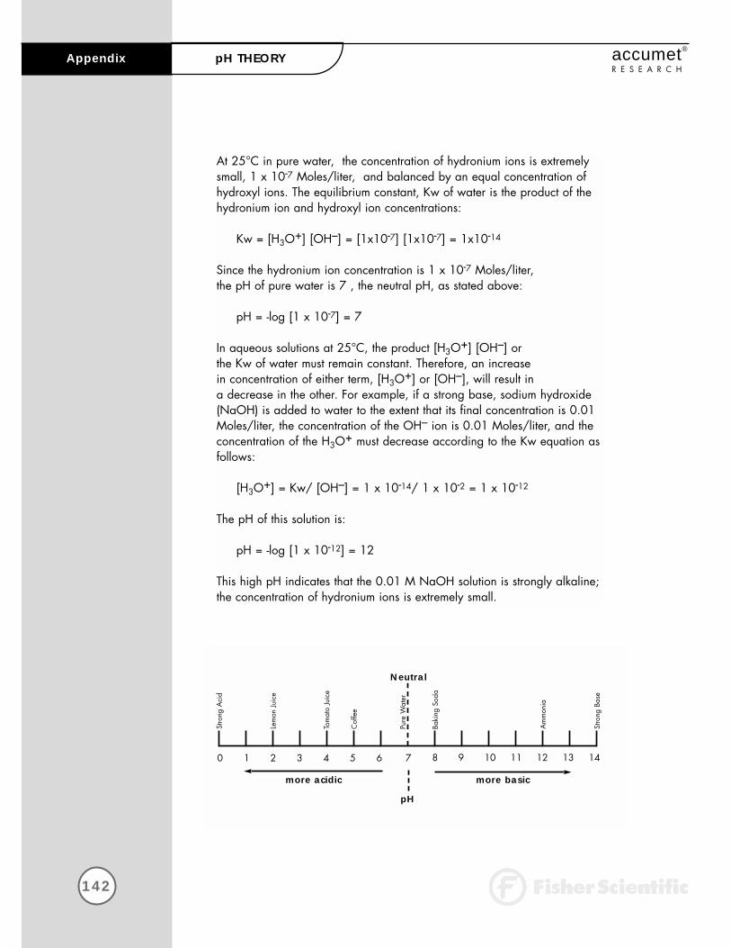
At 25°C in pure water, the concentration of hydronium ions is extremelysmall, 1 x 10⁻⁷ Moles/liter, and balanced by an equal concentration ofhydroxyl ions. The equilibrium constant, Kw of water is the product of thehydronium ion and hydroxyl ion concentrations:
Kw = [H3O+] [OH–] = [1x10⁻⁷] [1x10⁻⁷] = 1x10-14
Since the hydronium ion concentration is 1 x 10⁻⁷ Moles/liter, the pH of pure water is 7 , the neutral pH, as stated above:
pH = -log [1 x 10⁻⁷] = 7
In aqueous solutions at 25°C, the product [H3O+] [OH–] or the Kw of water must remain constant. Therefore, an increase in concentration of either term, [H3O+] or [OH–], will result in a decrease in the other. For example, if a strong base, sodium hydroxide (NaOH) is added to water to the extent that its final concentration is 0.01Moles/liter, the concentration of the OH– ion is 0.01 Moles/liter, and theconcentration of the H3O+ must decrease according to the Kw equation asfollows:
[H3O+] = Kw/ [OH–] = 1 x 10-14/ 1 x 10-2 = 1 x 10-12
The pH of this solution is:
pH = -log [1 x 10-12] = 12
This high pH indicates that the 0.01 M NaOH solution is strongly alkaline;the concentration of hydronium ions is extremely small.
142
Appendix accumet®
R E S E A R C HpH THEORY
0 1 2 3 4 5 6 8 9 10 11 12 13 147
pH
Neutral
more acidic more basic
Stro
ng A
cid
Lem
on J
uice
Tom
ato
Juic
e
Cof
fee
Pure
Wat
er
Baki
ng S
oda
Am
mon
ia
Stro
ng B
ase

143
Appendixaccumet®
R E S E A R C HpH THEORY
pH MeasurementThe pH value of a sample can be determined in several ways. Theseinclude the use of organic dyes which change color in certain pH ranges.The dyes can be added directly to the solution or impregnated onto paperwhich may be dipped into the solution. At best, these "colorimetric" methods yield approximate pH values, often with an accuracy of plus or minus 0.5 pH units.
The preferred and most accurate way to measure a pH value is the potentiometric measurement, using a pH electrode, a reference electrode,and a pH meter. This method is based on the fact that certain electrodes,immersed in solution, produce a millivolt potential (i.e. voltage ) that isrelated to the hydronium ion concentration or pH of a solution in a precise way.
The relationship between the electrode's voltage and the solution pH isdefined by the Nernst equation:
2.3RTEmeas = E* – ( )(pH)nF
In this equation, Emeas is the voltage output of the electrodes, E* is the totalof all other voltages in the system including the reference voltage, R is theGas Law constant, T is the temperature in °Kelvin, n is the charge on thehydronium ion (+1), and F is the Faraday constant.
pH MeterThe pH meter is a sensitive voltmeter capable of accurately measuringsmall voltage differences between the pH electrode and the reference electrode. This voltage difference is amplified, and shown as a pH reading. Almost all modern meters are microprocessor controlled, and programmed to use electrode voltages, efficiency, and temperature to calculate an accurate pH for the sample. Since the voltage output from different electrodes will vary, it is essential to calibrate a pH meter. Theability to calibrate or to standardize a pH meter permits the meter to matchthe pH reading on the meter with the known pH value of a buffer solution.For best accuracy, it is recommended that at least two buffer solutions beused to calibrate a pH meter. Buffer solutions are available as ready-to-usesolutions, concentrated solutions, capsules, or prepackaged salts. The following table lists three of the most widely used NIST buffers along with their pH values at different temperatures.
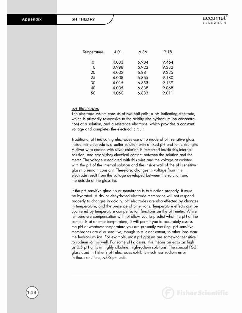
144
Appendix accumet®
R E S E A R C HpH THEORY
Temperature 4.01 6.86 9.18
0 4.003 6.984 9.46410 3.998 6.923 9.33220 4.002 6.881 9.22525 4.008 6.865 9.18030 4.015 6.853 9.13940 4.035 6.838 9.06850 4.060 6.833 9.011
pH ElectrodesThe electrode system consists of two half cells: a pH indicating electrode,which is primarily responsive to the acidity (the hydronium ion concentra-tion) of a solution, and a reference electrode, which provides a constantvoltage and completes the electrical circuit.
Traditional pH indicating electrodes use a tip made of pH sensitive glass.Inside this electrode is a buffer solution with a fixed pH and ionic strength.A silver wire coated with silver chloride is immersed inside this internalsolution, and establishes electrical contact between the solution and themeter. The voltage associated with this wire and the voltage associatedwith the pH of the internal solution and the inside wall of the pH sensitiveglass tip remain constant. Therefore, changes in voltage from this electrode result from the voltage developed between the solution and the outside of the glass tip.
If the pH sensitive glass tip or membrane is to function properly, it must be hydrated. A dry or dehydrated electrode membrane will not respond properly to changes in acidity. pH electrodes are also effected by changesin temperature, and the presence of other ions. Temperature effects can becountered by temperature compensation functions on the pH meter. Whiletemperature compensation will not allow you to predict what the pH of thesample is at another temperature, it will permit you to accurately assess the pH at whatever temperature you are presently working. pH sensitivemembranes are also sensitive, though to a lesser extent, to other ions thanthe hydronium ion. For example, most pH glasses are somewhat sensitiveto sodium ion as well. For some pH glasses, this means an error as highas 0.5 pH units in highly alkaline, high-sodium solutions. The special FS-5glass used in Fisher's pH electrodes exhibits much less sodium error in these solutions, <.05 pH units.

145
Appendixaccumet®
R E S E A R C HpH THEORY
Reference electrodes typically consist of three elements: an internal reference electrode, a filling solution, and a reference junction throughwhich the filling solution can "flow", and provide electrical contact with the sample and the internal reference electrode. The most convenient internal reference electrodes are made from a metal (such as silver or mercury) and its sparingly soluble salt (silver chloride or mercurous chloride). The filling solution is most often a concentrated solution of potassium chloride. Most problems with reference electrodes are associated with the interruption or blockage of flow of the potassium chloride fill solution through the reference junction.
The classic electrode pair, separate pH indicating and reference half cells, offer you unmatched versatility to match the needs of your sample.This approach makes for the highest accuracy, as well as low replacementcosts, since usually only one of the pair is broken or malfunctioning.
However, the pH indicating half-cell and the reference half-cell can bemerged into one electrode - a combination electrode. Combination electrodes are quite popular for they offer distinct advantages in convenience and compactness. Some combination electrodes also incorporate an ATC probe into their body also, providing temperaturereadout and compensation with meters equipped with these features.Newer combination electrodes are available in which the glass pH membrane sensor has been replaced with a field effect transistor or FET.All of Fisher Scientific's AB and AR meters are capable of using this typeof electrode by direct connection (except AB30).

146
Appendix accumet®
R E S E A R C HISE THEORY
Ion selective electrodes (ISE) respond to ionic activity or concentration in a liquid because of the characteristics of the electrode’s sensing membrane.Ideally, the ISE develops an electrical potential which is proportional to theactivity or concentration of the ion for which the membrane is selective. Forexample, the fluoride electrode can be used to directly sense fluoride ionin drinking water. Analyses utilizing ion selective electrodes offer theadvantages of speed, ease-of-operation, low cost, and versatility over other analytical techniques. The ISE can measure the ion concentration of samples at very high levels ( > 1000ppm ) to very low levels ( < 1ppm ).
When an ISE, the indicator electrode, and a reference electrode areplaced in a solution, and connected to a pH/mV/ion meter, they form a potentiometric cell. At equilibrium, the meter measures the potential difference between the ISE and the reference electrode. This millivolt potential is proportional to the activity of the ion of interest, and the relationship is defined by the Nernst equation:
RTE = E* ±2.3 (log a) wherenF
E is the measured potentialE* is the sum of the standard potential and all other constant
potentials of the systemR is the gas constantT is the temperature in °KF is Faraday’s constantn is the valence of the ion being measured
Activity, a, is not the same as concentration. It is a thermodynamic function whose value is influenced by the ionic environment in which the ion exists. Activity and concentration are the same in very dilute, ideal solutions. In non-ideal solutions, activity and concentration are related by an “activity coefficient“.
ISEs sense the activity of free, uncomplexed ions rather than concentration.However, by calibrating the meter with standards with a similar ionic back-ground as the sample, the difference between activity and concentrationbecomes negligible. Most often this is achieved by adding an ionicstrength adjustor to both samples and standards. The Nernst equationbecomes:
RTE = E* ±2.3 (log c) wherenF
c is the concentration of the ion of interest.
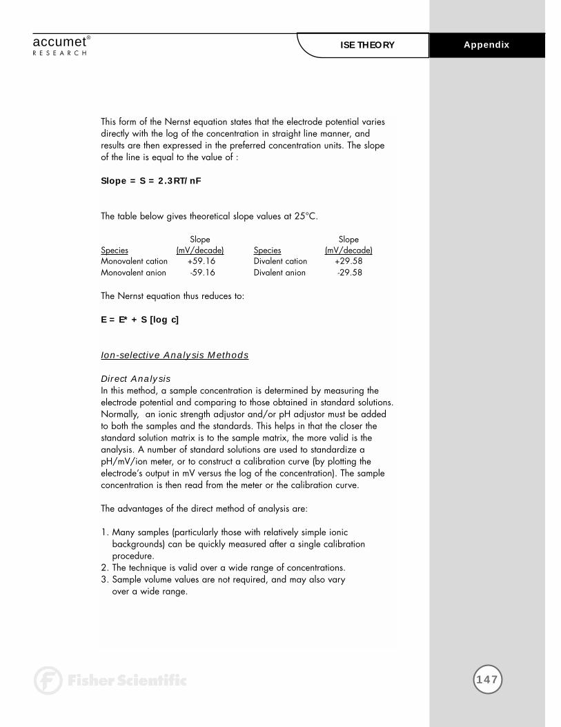
147
Appendixaccumet®
R E S E A R C HISE THEORY
This form of the Nernst equation states that the electrode potential variesdirectly with the log of the concentration in straight line manner, andresults are then expressed in the preferred concentration units. The slope of the line is equal to the value of :
Slope = S = 2.3RT/nF
The table below gives theoretical slope values at 25°C.
Slope Slope Species (mV/decade) Species (mV/decade)Monovalent cation +59.16 Divalent cation +29.58Monovalent anion -59.16 Divalent anion -29.58
The Nernst equation thus reduces to:
E = E* + S [log c]
Ion-selective Analysis Methods
Direct AnalysisIn this method, a sample concentration is determined by measuring theelectrode potential and comparing to those obtained in standard solutions.Normally, an ionic strength adjustor and/or pH adjustor must be addedto both the samples and the standards. This helps in that the closer thestandard solution matrix is to the sample matrix, the more valid is theanalysis. A number of standard solutions are used to standardize apH/mV/ion meter, or to construct a calibration curve (by plotting the electrode’s output in mV versus the log of the concentration). The sampleconcentration is then read from the meter or the calibration curve.
The advantages of the direct method of analysis are:
1. Many samples (particularly those with relatively simple ionic backgrounds) can be quickly measured after a single calibration procedure.
2. The technique is valid over a wide range of concentrations.3. Sample volume values are not required, and may also vary
over a wide range.

Incremental MethodsThese procedures can reduce errors caused by temperature variations,complex matrices, and complexation. They are also useful for applicationswhere only occasional samples are analyzed. Incremental methodsinclude: Known Addition, Known Subtraction, Analyte Addition, andAnalyte Subtraction.
Known Addition and Known SubtractionWith the Known Addition and Known Subtraction methods, the initial millivolt output of the electrode in the sample solution is measured. Then an aliquot of standard solution is added, and a final millivolt potential ismeasured. The concentration of the sample can then be computed from theobserved change in the millivolt readings before and after the addition.The techniques differ in that with Known Addition the standard added isthe same ionic species as that being measured. With Known Subtraction,the measured ion is not the same as the one being added via the standard. For example, a chloride ISE can be immersed in sample for a chloride measurement. If a silver standard is added to the sample, AgCl precipitates, effectively removing or subtracting chloride ion from the sample.
Equations for known addition and known subtraction calculations are asfollow:
Known Addition
Cstd VstdCs =
(Vs + Vstd)10∆E/S – Vs
Known Subtraction
Cstd VstdCs = where
Vs – (Vs + Vstd)10∆E/S
Cs is the concentration of the sample; Cstd is the concentration of the standard; Vs is the sample volume; Vstd is the standard volume; ∆E is thedifference in millivolt readings from the electrode; and S is the slope of the electrode determined in a previous standardization.
Whereas the direct method is suitable for samples with fairly uncomplicat-ed ionic matrices, the addition methods are advantageous with samplesthat have complex matrices, samples in which no ISA is added, samples in which excess complexing species are present, and samples whose concentration is in the non-linear region on the electrode response curve.
148
Appendix accumet®
R E S E A R C HISE THEORY

149
Appendixaccumet®
R E S E A R C HISE THEORY
Analyte Addition and Analyte Subtraction
In the Analyte methods, the initial millivolt reading is taken with the electrode immersed in the standard; then an aliquot of sample is added,and the final millivolt reading is taken. Sample concentration is calculatedfrom the change in the millivolt readings.
Analyte Addition
Vs + Vstd VstdCs = Cstd [( )10∆E/S – ( )]Vs Vs
Analyte Subtraction
Vstd Vs + VstdCs = Cstd [( ) – ( )10∆E/S]Vs Vs
As with known addition, with analyte addition the sample and the standard solution contain the same ion being measured. With analyte subtraction, the ion being measured is in the standard solution, and not inthe sample solution. For example, a fluoride standard and a fluoride ISEmight be used to measure to aluminum concentration of a sample. Whenthe sample containing aluminum is added to the standard it reduces themeasured fluoride content of the standard. The amount of reduction is proportional to the aluminum in the sample.
The analyte methods offer the same advantages as do the addition methods in that they effectively deal with complex samples. A distinctadvantage of the analyte subtraction method is that it can be used in cases where an ISE does not exist for a given species, such as aluminumin the example cited.

150
Replacement Parts accumet®
R E S E A R C H
Replacement Parts
Description Fisher Catalog NumberAccumet pH combination electrode, single junction, Ag/AgCl reference, glass body, BNC connector . . . . . . . . . . . . . . . . 13-620-285ATC Probe . . . . . . . . . . . . . . . . . . . . . . . . . . . . . . . . . . . . . . . . . . 13-620-19AccuFlex electrode support arm. . . . . . . . . . . . . . . . . . . . . . . . . . . . 13-637-671Electrode support bracket . . . . . . . . . . . . . . . . . . . . . . . . . . . . . . . . 13-637-671APower Supplies: 115V, US plug . . . . . . . . . . . . . . . . . . . . . . . . . . 13-636-100
230V, UK plug . . . . . . . . . . . . . . . . . . . . . . . . . . 13-636-101230V, Europe plug. . . . . . . . . . . . . . . . . . . . . . . . 13-636-102
Operator’s Manual . . . . . . . . . . . . . . . . . . . . . . . . . . . . . . . . . . . . 13-636-AR50MBNC Shorting cap . . . . . . . . . . . . . . . . . . . . . . . . . . . . . . . . . . . . 13-620-99
Accessories
pH Electrodes Fisher Catalog NumberAccumet pH combination electrode, single junction, calomel reference, glass body, BNC connector. . . . . . . . . . . . . . . . . . 13-620-286Accumet 3-in-1 pH/ATC combination electrode, single junction,Ag/AgCl reference, glass body, BNC connector . . . . . . . . . . . . . . . . 13-620-530Accumet 3-in-1 pH/ATC combination electrode, single junction,calomel reference, glass body, BNC connector. . . . . . . . . . . . . . . . . . 13-620-531AccupHast pH combination electrode, double junction,glass body, BNC connector . . . . . . . . . . . . . . . . . . . . . . . . . . . . . . 13-620-296AccupHast pH combination electrode, double junction, epoxy body, BNC connector . . . . . . . . . . . . . . . . . . . . . . . . . . . . . . 13-620-298AccuFET solid state pH/ATC combination electrode, Ag/AgCl gel reference . . . . . . . . . . . . . . . . . . . . . . . . . . . . . . . . . 13-620-755
pH Buffers and Solutions
pH Color Ingredients Size Fisher Catalog Number4.00 Red Potassium Biphthalate 500 mL SB101-5007.00 Yellow Potassium Phosphate Monobasic 500 mL SB107-500
& Sodium Hyroxide10.00 Blue Potassium Carbonate, Potassium 500 mL SB115-500
Borate & Potassium HydroxideFisher Buffer-Pac (500mL ea. of color coded 3x500 mL SB105
pH 4, 7, and 10 buffers)4.00 Red Individual Tear open pH Packets 20/box SB47.00 Yellow Individual Tear open pH Packets 20/box SB710.00 Blue Individual Tear open pH Packets 20/box SB10
Gray Electrode Rinse Individual Tear open pH Packets 20/box SB15Electrode Storage Solution 1L SE40-1
To place an order, call 1-800/766-7000For technical support, call 1-800/943-2006
For a complete selection of electrodes and acces-sories, please refer to theFisher 1998/99 Catalog,or contact your FisherScientific sales representative.

![SL3488 instruction manual -V1[1].52-20080429 · Instruction Manual Rev 1.2 ... will be affected the meter’s working and reduce the meter’s life or cause some malfunctions.](https://cdn.vdocument.in/doc/165x107/5c91f5ae09d3f26a458bae12/sl3488-instruction-manual-v1152-instruction-manual-rev-12-will-be.jpg)


