EWC Controls is proud to announce that the Ultra-Zone® UT3000 Zone Control has been approved to operate with the Daikin or Goodman ComfortNet™Inverter based HVAC systems!
The Daikin Inverter A/C or HP will provide variable BTU capacity based on a proportional demand from the Ultra-Zone UT3000 zone controller.
If you are installing a Daikin or Goodman Inverter system and a CTK04 thermostat, along with the Ultra-Zone UT3000 Zone Controller, these start-up instructions on page 1 & 2, apply to you.
Upon power-up, the CTK04 communicating thermostat facilitates a “System Test” on the Inverter system. This test is required to confirm the Inverter system settings and parameters. Normal cooling operations are not allowed until this test is complete. NOTE: If the “System Test” has already been performed with an existing CTK04, there is no need to perform it again via the UT3000.
The “System Test” may last 5 to 15 minutes and MUST NOT BE INTERRUPTED! The system test can be performed via any CTK04 thermostat, connected to any communicating zone terminal block, on the UT3000 zone controller.
IMPORTANT: ALL ZONE THERMOSTATS MUST BE OFF!!! (No Cool, Heat or Fan), including the CTK04 thermostat being used to initiate the System Test.
Follow these steps to perform a “System Test” verify “Refrigerant Charge” or “System Pump-Down”.
1. Any of the above “Sealed System” functions can be performed via the CTK04 thermostat in any zone. ALL zone thermostats must be set to “OFF” with no demands for Cool, Heat or Fan.
2. See the Daikin Inverter Condensing Unit Installation and Service Reference for instructions on performing the “System Test” verifying the “Refrigerant Charge” or “System Pump-Down” for repairs.
3. Using the CTK04 in any zone, navigate to and access the “ComfortNet User Menu”. Select the “EQUIP TEST” tab and then “SYSTEM TEST” in order to start the System Test. Refer to the next page for thermostat graphics of this procedure.
4. DO NOT INTERRUPT THE TEST!!! After the system test is complete and/or the refrigerant charge has been verified, you may decide to re-access the Climate Talk User Menu and modify other settings such as (Cool or Heat Trim Settings, Cooling Profile, Temperature Rise, Clear Diagnostic Faults, etc). Contact EWC Controls Technical Support if you have questions.
5. After these tasks have been performed, you may now set all zones to demand conditioned air.
FIT™
P# 090376A0185 Rev. F Copyright © 02/02/2016 EWC Controls Inc. 385 Highway 33 Englishtown, NJ 07726 800-446-3110 FAX 732-446-5362 E-Mail- [email protected]
Communicating Zone Control System U.S. Patent No. 9,253,260
3000Addendum sheet for UT3000 Code versions 1.33 - 1.50
APPLIES TO DAIKIN INVERTER SYSTEMS ONLY
®
STOP & read this bulletin before you start the Inverter or perform repairs on the sealed system!
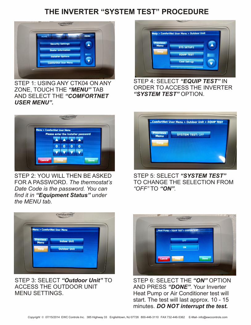
STEP 1: USING ANY CTK04 ON ANY ZONE, TOUCH THE “MENU” TABAND SELECT THE “COMFORTNET USER MENU”.
STEP 3: SELECT “Outdoor Unit” TO ACCESS THE OUTDOOR UNIT MENU SETTINGS.
STEP 6: SELECT THE “ON” OPTION AND PRESS “DONE”. Your Inverter Heat Pump or Air Conditioner test will start. The test will last approx. 10 - 15 minutes. DO NOT interrupt the test.
STEP 5: SELECT “SYSTEM TEST” TO CHANGE THE SELECTION FROM “OFF” TO “ON”.
STEP 4: SELECT “EQUIP TEST” IN ORDER TO ACCESS THE INVERTER “SYSTEM TEST” OPTION.
THE INVERTER “SYSTEM TEST” PROCEDURE
STEP 2: YOU WILL THEN BE ASKED FOR A PASSWORD. The thermostat’s Date Code is the password. You can find it in “Equipment Status” under the MENU tab.
Copyright © 07/15/2014 EWC Controls Inc. 385 Highway 33 Englishtown, NJ 07726 800-446-3110 FAX 732-446-5362 E-Mail- [email protected]

Copyright © 07/15/2014 EWC Controls Inc. 385 Highway 33 Englishtown, NJ 07726 800-446-3110 FAX 732-446-5362 E-Mail- [email protected]
1. Zone Weight feature (1.33 -1.50 only) allows the Installer to select the weight value of each zone. Imposes a limit on the allowable system capacity by zone.
2. W2 Lockout feature defaults to 99F. You must manually set this value (typically 45F - 55F) if you decide to utilize it.
3. OAS-SP (Outdoor Air Sensor-Setpoint) now defaults to OFF. You must manually set this value (typically 30F - 35F) if you decide to utilize it.
4. PID LOOP is now capped at the assigned zone weight(s) multiplied by the detected zone thermostat demand(s) multiplied by 3.
5. Default Dampers CLOSED or OPEN after the purge cycle, (during idle periods).
6. UT3000 Code Version is displayed upon power up and in the programming menu.
7. Total Zones feature allows the Installer to select the exact number of zones on each panel.
8. SAS RSP DLY (Supply Air Sensor Response Delay) now defaults to 22 seconds (22s).
9. Updated “Electronic” Twinning Diagrams on pages 4, 5 & 6.
Communicating Zone Control System3000®
NEW MENU ITEMS and UPDATES
Addendum sheet for UT3000 Code versions 1.33 - 1.50
U.S. Patent No. 9,253,260
TABLE 1FEATURE DEFAULT RANGE TO SELECT
System Type
HP Type
T-Stat Type
Rev Valve
Fan Mode
Heat/Cool
NONDual Fuel
RV ‘O’
Gas
OAS SP OFF
O.T. Offset 8° F
7° FU.T. Offset
SAS HP TGT
SAS Gas TGT
SAS Cool TGT
112° F
142° F
47° F
PURGE FAN
SAS RSP DLY
W2 Threshold
22s
95%
25%
Heat Pump or Heat/Cool
Dual Fuel or Non-Dual Fuel
Heat Pump or Heat/Cool
‘O’ Type RV or ‘B’ Type RV
GAS or HYDRO (Electric)
OFF or 7° to 42° F
5° to 20° F
5° to 12° F
90° to 120° F
120° to 170° F
40° to 60° F
10seconds - 180seconds
65% - 99% (Adj. in 5 point increments)
25% - 100% (Adj. in 25 point increments)
Heat/Cool
15%
0% to 100% Zone 1 Weight 70%
Total Zones 2 or 3 zones per panel 3
Limit SAS PID
Yes or No N
DMP DFLT Open or Close Open
W2 lockout 99° F 20° to 99° F
0% to 100%
0% to 100% 15%
Zone 2 Weight
Zone 3 Weight

EWC Controls Inc. 385 Highway 33 Englishtown, NJ 07726 800-446-3110 FAX 732-446-5362 E-Mail- [email protected]
UT3000 PANEL TWINNING PROCEDURES
Refer to the Graphics on Pages 4, 5 & 6.
1. Mount Panel “A” (Master) and Panel “B” (Slaves) in close proximity to the HVAC system and each other.
2. Install a dedicated 24v 50 or 60va listed transformer and run 24v power to both UT3000’s. Make sure to maintain polarity. You may use separate 40va transformers if desired. DO NOT exceed 60va on any transformers. * Do not power up yet.
3. Connect the HVAC system low voltage wires to the Panel “A” SYSTEM block as shown.
4. Connect a CTK04 communicating thermostat to the Zone 1 “communicating” Tstat block on Panel “A”.
5. Connect communicating or legacy 24v thermostats to all other Tstat blocks on Panel “A” & “B” as desired.
6. Panel “A” and “B” default to Heat/Cool type thermostats. When installing Legacy HP thermostats, access both Menus and reprogram to Heat Pump type Thermostats. Type “O” reversing valve. 7. Connect the “twinning” wire connections between the “communicating” SYSTEM output block of Panel “B” to the “communicating” Zone 3 T-stat input of Panel “A”. NOTE: You may connect to any unused zone on Panel “A” that you desire.
8. Install one Supply Air Sensor and connect the wires to the SAS terminals of Panel “A” only. Panel B does not need any sensor connections. Panel “A” will share that data with Panel “B”.
9. Panel “A” will retrieve the outside air temperature from the outdoor unit. There is no need to install an outside air sensor to the UT3000. Panel “A” will share that data with Panel “B”.
10. Power Up the entire HVAC system and power up the UT3000’s.
11. Panel “A” Master and Panel “B” Slave will “talk” to each other and share all necessary system and zone control information.
12. Set all thermostats to operational mode and operate the HVAC system in both Heating and Cooling modes, to confirm proper operation. Call EWC Controls Engineering Dept. if you have questions.
3000 U.S. Patent No. 9,253,260
C 2
1
Ty
pic
al C
om
m T
he
rmo
sta
tC
2 1
R
Ty
pic
al C
om
m T
he
rmo
sta
t
C
EW
C
SYST
EM
CO
NTR
OL
PC
PO C 2 1 R
C PC
PO
C 2 1 R
C
W/E
O/B Y R G
W2
/E
W1/B
O Y G RH
RC
C
C 2 1 R
C W/E
O/B
Y R G W/E
O/B
Y R G RE
LA
YO
NE
ZO
NE
ZO
NE
ZO
NE
IAQ
RE
LA
Y
SY
ST
EM
ZO
NE
3 O
PE
N
ZO
NE
2 O
PE
N
ZO
NE
1 O
PE
N
IAQ
RE
LA
Y
W2
/ E
ME
RG
EN
CY
HE
AT
/ B
CO
MP
RE
SS
OR
FA
N
C 2 1
LE
D1
6
LE
D1
7
LE
D1
5
LE
D1
4
LE
D1
3
LE
D1
2
LE
D11
LE
D1
0
SWT1
SWT2
SWT3
SWT4
CO
NT
RA
ST
LE
D1
9
LE
D2
2
RC
/RH
LIN
K
JM
P1
LE
D2
0
BIA
SIN
GT
ER
MIN
AT
ION
Clim
ate
Ta
lk®
SY
ST
EM
RE
CE
IVE
DA
TA
D A M P E R
D A M P E R D A M P E R
C PC
PO
S Y S T E M
F8
D2
0C
42
L2
+C
9+
D2
8
FB2
C8
+U
17
D1
9
R3
8D
18
R3
7D
17
R4
1
R4
0
R7
9
F7
F6
C3
2U
12
C1
6
R1
3K9
D1
6
D1
5
C1
5D
14
D1
3R2
3
R2
4
R2
5
R2
6
C3
1
C2
9
C2
8
C2
6
R7
1
R7
5
R7
7
R8
4
R8
3
R7
6
R7
4
R7
0
R6
9
R6
8
C3
0
R4
6
U1
6R1
16
R1
11
U1
5R1
14
R1
10
U1
4R1
15
R1
13
R1
12
R4
3
R1
18
C4
1
R4
5
R1
19
C4
3
R1
09
R3
9
D1
2K8
R1
2
D1
1K7
R1
1
D1
0
R1
0K6
D9
R9
D8
C2
1
Y1
C1
4
U3
U4
C2
2
R1
17
J1
R2
7
C1
3
R2
8
U7
U6
C1
9
U1
8
R8
R7
R6
C1
2
R6
7
C2
5
R6
6
R6
4
R6
3
R6
2
R6
5
R7
3C
24
C2
7R7
2R5
8
D2
5F1
7F5
R5
7
C2
3
U1
1
R6
0R8
0
R6
1
R9
1
R8
8
R9
4
R9
3
R9
2
R9
6
R9
7
R9
5
C3
3
C3
4
R8
6
R8
5R8
7C
35
C3
6R9
8
F1
6
F2
1
D2
4F1
5
R5
3R5
6
R8
1R5
5
K3
F4
F1
4D
23
R5
2R5
4C
20
U1
0
D2
7
D1
D2
FB1
C2
C1
C3
++
+
U1
9
C1
0
R1
01
C3
7R9
0
R1
03
R1
02
R1
04
R1
07
R1
05
R1
06
R1
08
C3
8
C3
9
R8
9
R1
00
R9
9C
40
D2
1F1
1
C1
8R4
7R4
9
F1
3
F2
2
F3
D2
2F1
2K2 R4
8
D5
R5
1
R8
2
R5
0
U9
R C
F1
K5
2
CZO
NE
R
F1
9
F2
0
D2
6F1
8
1
3
C4
C5
++
L1
D3
U2
R2
2
R3
5R3
6
R3
3
R3
4
OA
S
SA
S
Z1
RX
D
Z2
RX
DZ
3R
XD
LE
D2
1
NC
NO C
SYS
h0
67c0
00f0
67
W Y G R
®
1 2 3
ON
®
Co
mm
un
ica
tin
gA
IR H
AN
DL
ER
OR
F
UR
NA
CE
Co
mm
un
ica
tin
gO
UT
DO
OR
HE
AT
PU
MP
OR
CO
ND
EN
SIN
G U
NIT
21 CR
21 CR
White
Ye
llow
Gre
en
Re
d
C
EW
C
SYST
EM
CO
NTR
OL
PC
PO C 2 1 R
C PC
PO
C 2 1 R
C
W/E
O/B Y R G
W2/E
W1
/B
O Y G RH
RC
C
C 2 1 R
C W/E
O/B
Y R G C W/E
O/B
Y R G RE
LA
YO
NE
ZO
NE
ZO
NE
ZO
NE
ZO
NE
IAQ
RE
LA
Y
SY
ST
EM
ZO
NE
3 O
PE
N
ZO
NE
2 O
PE
N
ZO
NE
1 O
PE
N
IAQ
RE
LA
Y
W2
/ E
ME
RG
EN
CY
HE
AT
/ B
CO
MP
RE
SS
OR
FA
N
C 2 1 R
LE
D1
6
LE
D1
7
LE
D1
5
LE
D1
4
LE
D1
3
LE
D1
2
LE
D11
LE
D1
0
SWT1
SWT2
SWT3
SWT4
CO
NT
RA
ST
LE
D1
9
LE
D2
2
RC
/RH
LIN
K
JM
P1
LE
D2
0
BIA
SIN
GT
ER
MIN
AT
ION
Clim
ate
Ta
lk®
SY
ST
EM
RE
CE
IVE
DA
TA
D A M P E R
D A M P E R D A M P E R
C PC
PO
S Y S T E M
F8
D2
0C
42
L2
+C
9+
D2
8
FB2
C8
+U
17
D1
9
R3
8D
18
R3
7D
17
R4
1
R4
0
R7
9
F7
F6
C3
2U
12
C1
6
R1
3K9
D1
6
D1
5
C1
5D
14
D1
3R2
3
R2
4
R2
5
R2
6
C3
1
C2
9
C2
8
C2
6
R7
1
R7
5
R7
7
R8
4
R8
3
R7
6
R7
4
R7
0
R6
9
R6
8
C3
0
R4
6
U1
6R1
16
R1
11
U1
5R1
14
R1
10
U1
4R1
15
R1
13
R1
12
R4
3
R1
18
C4
1
R4
5
R1
19
C4
3
R1
09
R3
9
D1
2K8
R1
2
D1
1K7
R1
1
D1
0
R1
0K6
D9
R9
D8
C2
1
Y1
C1
4
U3
U4
C2
2
R1
17
J1
R2
7
C1
3
R2
8
U7
U6
C1
9
U1
8
R8
R7
R6
C1
2
R6
7
C2
5
R6
6
R6
4
R6
3
R6
2F1
9
F2
0
R6
5
R7
3C
24
C2
7R7
2R5
8D
26
F1
8
D2
5F1
7F5
R5
7
C2
3
U1
1
R6
0R8
0
R6
1
R9
1
R8
8
R9
4
R9
3
R9
2
R9
6
R9
7
R9
5
C3
3
C3
4
R8
6
R8
5R8
7C
35
C3
6R9
8
F1
6
F2
1
D2
4F1
5
R5
3R5
6
R8
1R5
5
K3
F4
F1
4D
23
R5
2R5
4C
20
U1
0
D2
7
D1
D2
FB1
C2
C1
C3
++
+
U1
9
C1
0
R1
01
C3
7R9
0
R1
03
R1
02
R1
04
R1
07
R1
05
R1
06
R1
08
C3
8
C3
9
R8
9
R1
00
R9
9C
40
D2
1F1
1
C1
8R4
7R4
9
F1
3
F2
2
F3
D2
2F1
2K2 R4
8
D5
R5
1
R8
2
R5
0
U9
R C
F1
K5
2 1
3
C4
C5
++
L1
D3
U2
R2
2
R3
5R3
6
R3
3
R3
4
OA
S
SA
S
Z1
RX
D
Z2
RX
DZ
3R
XD
LE
D2
1
NC
NO C
Z2
h10
0c00
0f00
0
W Y G R
®
1 2 3
ON
®
C 2
1R
CO
MP
OP
C
46
1
CO
MP
OP
C
46
1
CO
MP
OP
C
46
1
MA
ST
ER
PA
NE
LS
LA
VE
PA
NE
L
F
rom
6
0 v
aT
ran
sfo
rme
r P
ow
eri
ng
M
as
ter
P
an
el
Typi
cal Z
one
Dam
per
Ty
pic
al C
om
m T
he
rmo
sta
t
Th
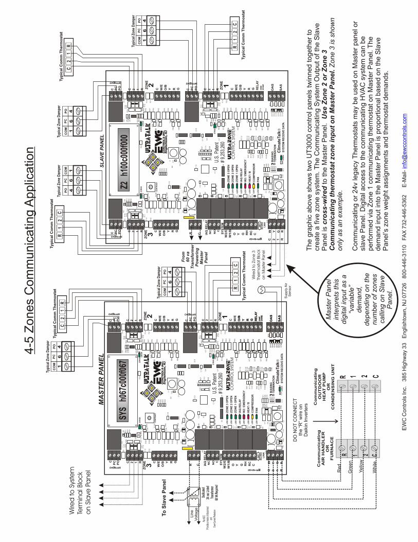
e g
rap
hic
ab
ove
sh
ow
s tw
o U
T3
00
0 c
on
tro
l pa
ne
ls tw
inn
ed
to
ge
the
r to
cr
ea
te a
fiv
e z
on
e s
yst
em
. T
he
Co
mm
un
ica
ting
Sys
tem
Ou
tpu
t o
f th
e S
lave
P
an
el i
s c
ros
s-w
ire
d to
th
e M
ast
er
Pa
ne
l. U
se
Zo
ne
2 o
r Z
on
e 3
C
om
mu
nic
ati
ng
th
erm
os
tat
zon
e in
pu
t o
n M
as
ter
Pa
ne
l. Z
on
e 3
is s
ho
wn
o
nly
as
an
exa
mp
le.
Co
mm
un
ica
ting
or
24
v le
ga
cy T
he
rmo
sta
ts m
ay
be
use
d o
n M
ast
er
pa
ne
l or
sla
ve P
an
el.
Dig
ital a
cce
ss to
th
e c
om
mu
nic
atin
g H
VA
C s
yste
m c
an
be
p
erf
orm
ed
via
Zo
ne
1 c
om
mu
nic
atin
g th
erm
ost
at o
n M
ast
er
Pa
ne
l. T
he
d
em
an
d in
pu
t in
to th
e M
ast
er
Pa
ne
l is
pro
po
rtio
na
l ba
sed
on
th
e S
lave
P
an
el’s
zo
ne
we
igh
t a
ssig
nm
en
ts a
nd
th
erm
ost
at d
em
an
ds.
DO
NO
T C
ON
NE
CT
the
“R
” w
ire
on
D
aik
in In
vert
ers
O/B
Y R G RE
LA
YO
NE
ZO
NE
C1
6
D1
6
D1
5
C1
5D
14
D1
3R2
3
R2
4
R2
5
R2
6
C3
1
C2
9
C2
8
C2
6
R8
3
R7
6
R7
4
R7
0
R6
9
R6
8C
25
OA
S
SA
S
Su
pp
ly A
ir S
en
so
r
Ma
ste
r P
an
el
inte
rpre
ts th
is
dig
ital i
np
ut a
s a
“v
aria
ble
” d
em
an
d,
de
pe
nd
ing
on
th
e
nu
mb
er
of zo
ne
s ca
llin
g o
n S
lave
Pa
ne
l.
Ty
pic
al C
om
m T
he
rmo
sta
t
Typi
cal Z
one
Dam
per
Typi
cal Z
one
Dam
per
4-5
Zo
ne
s C
om
mu
nic
atin
g A
pp
lica
tion
R
D
edica
ted 2
4 vac
Liste
d
Tran
sform
er 60
VA R
equir
ed
Per N
EC
Prov
ide a
mean
s of d
iscon
nect
an
d
Over-
Curre
nt Pr
otecti
on
CO
MP
OP
C
46
1
To
Sla
ve
Pa
ne
l
L
ine
V
olta
ge
C 2
1R
Typi
cal Z
one
Dam
per
Ty
pic
al C
om
m T
he
rmo
sta
t
C 2
1R
CO
MP
OP
C
46
1
Typi
cal Z
one
Dam
per
Wire
d to
Zo
ne
3Th
erm
ost
at Blo
ck
on M
ast
er Pa
ne
l
Wire
d to
Sys
tem
Term
ina
l Blo
ck
on S
lave
Pa
ne
l
EW
C C
on
tro
ls In
c. 3
85
Hig
hw
ay
33
E
ng
lish
tow
n, N
J 0
77
26
8
00
-44
6-3
110
F
AX
73
2-4
46
-53
62
E
-Ma
il-
info
@e
wcc
on
tro
ls.c
om
U.S
. Pat
ent
# 9,
253,
260
U.S
. Pat
ent
# 9,
253,
260
C
EW
C
SYST
EM
CO
NTR
OL
PC
PO C 2 1 R
C PC
PO
C 2 1 R
C
W/E
O/B Y R G
W2
/E
W1
/B
O Y G RH
RC
C
C 2 1 R
C W/E
O/B
Y R G W/E
O/B
Y R G RE
LA
YO
NE
ZO
NE
ZO
NE
ZO
NE
IAQ
RE
LA
Y
SY
ST
EM
ZO
NE
3 O
PE
N
ZO
NE
2 O
PE
N
ZO
NE
1 O
PE
N
IAQ
RE
LA
Y
W2
/ E
ME
RG
EN
CY
HE
AT
/ B
CO
MP
RE
SS
OR
FA
N
C 2 1
LE
D1
6
LE
D1
7
LE
D1
5
LE
D1
4
LE
D1
3
LE
D1
2
LE
D11
LE
D1
0
SWT1
SWT2
SWT3
SWT4
CO
NT
RA
ST
LE
D1
9
LE
D2
2
RC
/RH
LIN
K
JM
P1
LE
D2
0
BIA
SIN
GT
ER
MIN
AT
ION
Clim
ate
Ta
lk®
SY
ST
EM
RE
CE
IVE
DA
TA
D A M P E R
D A M P E R D A M P E R
C PC
PO
S Y S T E M
F8
D2
0C
42
L2
+C
9+
D2
8
FB2
C8
+U
17
D1
9
R3
8D
18
R3
7D
17
R4
1
R4
0
R7
9
F7
F6
C3
2U
12
C1
6
R1
3K9
D1
6
D1
5
C1
5D
14
D1
3R2
3
R2
4
R2
5
R2
6
C3
1
C2
9
C2
8
C2
6
R7
1
R7
5
R7
7
R8
4
R8
3
R7
6
R7
4
R7
0
R6
9
R6
8
C3
0
R4
6
U1
6R1
16
R1
11
U1
5R1
14
R1
10
U1
4R1
15
R1
13
R1
12
R4
3
R1
18
C4
1
R4
5
R1
19
C4
3
R1
09
R3
9
D1
2K8
R1
2
D1
1K7
R1
1
D1
0
R1
0K6
D9
R9
D8
C2
1
Y1
C1
4
U3
U4
C2
2
R1
17
J1
R2
7
C1
3
R2
8
U7
U6
C1
9
U1
8
R8
R7
R6
C1
2
R6
7
C2
5
R6
6
R6
4
R6
3
R6
2
R6
5
R7
3C
24
C2
7R7
2R5
8
D2
5F1
7F5
R5
7
C2
3
U1
1
R6
0R8
0
R6
1
R9
1
R8
8
R9
4
R9
3
R9
2
R9
6
R9
7
R9
5
C3
3
C3
4
R8
6
R8
5R8
7C
35
C3
6R9
8
F1
6
F2
1
D2
4F1
5
R5
3R5
6
R8
1R5
5
K3
F4
F1
4D
23
R5
2R5
4C
20
U1
0
D2
7
D1
D2
FB1
C2
C1
C3
++
+
U1
9
C1
0
R1
01
C3
7R9
0
R1
03
R1
02
R1
04
R1
07
R1
05
R1
06
R1
08
C3
8
C3
9
R8
9
R1
00
R9
9C
40
D2
1F1
1
C1
8R4
7R4
9
F1
3
F2
2
F3
D2
2F1
2K2 R4
8
D5
R5
1
R8
2
R5
0
U9
R C
F1
K5
2
CZO
NE
R
F1
9
F2
0
D2
6F1
8
1
3
C4
C5
++
L1
D3
U2
R2
2
R3
5R3
6
R3
3
R3
4
OA
S
SA
S
Z1R
XD
Z2
RX
DZ
3R
XD
LE
D2
1
NC
NO C
SYS
h0
67c0
00f0
67
W Y G R
®
1 2 3
ON
®
Co
mm
un
ica
tin
gA
IR H
AN
DL
ER
OR
F
UR
NA
CE
Co
mm
un
ica
tin
gO
UT
DO
OR
HE
AT
PU
MP
OR
CO
ND
EN
SIN
G U
NIT
21 CR
21 CR
Wh
ite
Ye
llow
Gre
en
Re
d
D
edica
ted 2
4 vac
Liste
d
Tran
sform
er 60
VA R
equir
ed
Per N
EC
Prov
ide a
mean
s of d
iscon
nect
an
d
Over-
Curre
nt Pr
otecti
on
MA
ST
ER
PA
NE
L
L
ine
V
olta
ge
DO
NO
T C
ON
NE
CT
the
“R
” w
ire
on
D
aik
in In
vert
ers
O/B
Y R G RE
LA
YO
NE
ZO
NE
C1
6
D1
6
D1
5
C1
5D
14
D1
3R2
3
R2
4
R2
5
R2
6
C3
1
C2
9
C2
8
C2
6
R8
3
R7
6
R7
4
R7
0
R6
9
R6
8C
25
OA
S
SA
S
Sup
ply
Air
S
en
so
r
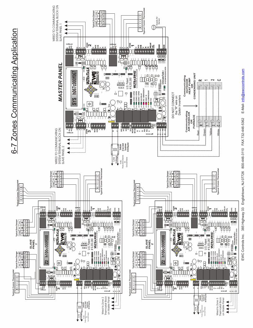
6-7
Zo
ne
s C
om
mu
nic
atin
g A
pp
lica
tion
C 2
1R
Ty
pic
al C
om
m T
he
rmo
sta
tC
2 1
R
Ty
pic
al C
om
m T
he
rmo
sta
t
C
EW
C
SYSTE
MC
ON
TRO
L
PC
PO C 2 1 R
C PC
PO
C 2 1 R
C
W/E
O/B Y R G
W2
/E
W1
/B
O Y G RH
RC
C
C 2 1 R
C W/E
O/B
Y R G C W/E
O/B
Y R G RE
LA
YO
NE
ZO
NE
ZO
NE
ZO
NE
ZO
NE
IAQ
RE
LA
Y
SY
ST
EM
ZO
NE
3 O
PE
N
ZO
NE
2 O
PE
N
ZO
NE
1 O
PE
N
IAQ
RE
LA
Y
W2
/ E
ME
RG
EN
CY
HE
AT
/ B
CO
MP
RE
SS
OR
FA
N
C 2 1 R
LE
D16
LE
D17
LE
D15
LE
D14
LE
D13
LE
D12
LE
D11
LE
D10
SW
T1
SW
T2
SW
T3
SW
T4
CO
NT
RA
ST
LE
D1
9
LE
D2
2
RC
/RH
LIN
K
JM
P1
LE
D2
0
BIA
SIN
GT
ER
MIN
AT
ION
Clim
ate
Ta
lk®
SY
ST
EM
RE
CE
IVE
DA
TA
D A M P E R
D A M P E R D A M P E R
C PC
PO
S Y S T E M
F8
D2
0C
42
L2
+C
9+
D2
8
FB2
C8
+U
17
D1
9
R3
8D
18
R3
7D
17
R4
1
R4
0
R7
9
F7
F6
C3
2U
12
C1
6
R1
3K9
D1
6
D1
5
C1
5D
14
D1
3R2
3
R2
4
R2
5
R2
6
C3
1
C2
9
C2
8
C2
6
R7
1
R7
5
R7
7
R8
4
R8
3
R7
6
R7
4
R7
0
R6
9
R6
8
C3
0
R4
6
U1
6R1
16
R1
11
U1
5R1
14
R1
10
U1
4R1
15
R1
13
R1
12
R4
3
R1
18
C4
1
R4
5
R1
19
C4
3
R1
09
R3
9
D1
2K8
R1
2
D1
1K7
R1
1
D1
0
R1
0K6
D9
R9
D8
C2
1
Y1
C1
4
U3
U4
C2
2
R1
17
J1
R2
7
C1
3
R2
8
U7
U6
C1
9
U1
8
R8
R7
R6
C1
2
R6
7
C2
5
R6
6
R6
4
R6
3
R6
2F1
9
F2
0
R6
5
R7
3C
24
C2
7R7
2R5
8D
26
F1
8
D2
5F1
7F5
R5
7
C2
3
U1
1
R6
0R8
0
R6
1
R9
1
R8
8
R9
4
R9
3
R9
2
R9
6
R9
7
R9
5
C3
3
C3
4
R8
6
R8
5
R8
7C
35
C3
6R9
8
F1
6
F2
1
D2
4F1
5
R5
3R5
6
R8
1R5
5
K3
F4
F1
4D
23
R5
2R5
4C
20
U1
0
D2
7
D1
D2
FB1
C2
C1
C3
++
+
U1
9
C1
0
R1
01
C3
7R9
0
R1
03
R1
02
R1
04
R1
07
R1
05
R1
06
R1
08
C3
8
C3
9
R8
9
R1
00
R9
9C
40
D2
1F1
1
C1
8R4
7R4
9
F1
3
F2
2
F3
D2
2F1
2K2 R4
8
D5
R5
1
R8
2
R5
0
U9
R C
F1
K5
2 1
3
C4
C5
++
L1
D3
U2
R2
2
R3
5R3
6
R3
3
R3
4
OA
S
SA
S
Z1R
XD
Z2R
XD
Z3R
XD
LE
D2
1
NC
NO C
Z2
h10
0c00
0f00
0
W Y G R
®
1 2 3
ON
®
CO
MP
OP
C
46
1
CO
MP
OP
C
46
1
CO
MP
OP
C
46
1
SL
AV
EP
AN
EL
1
C 2
1R
Ty
pic
al C
om
m T
he
rmo
sta
t
Ty
pic
al Z
on
e D
am
pe
r Ty
pic
al Z
on
e D
am
pe
r
Ty
pic
al Z
on
e D
am
pe
r
Dedi
cate
d
24 v
ac L
iste
d
Tra
nsfo
rmer
60
VA R
equi
red
P
er N
EC
Prov
ide
a m
eans
of d
iscon
nect
a
nd
O
ver-C
urre
nt P
rote
ctio
n
L
ine
Vo
lta
ge
C 2
1R
Ty
pic
al C
om
m T
he
rmo
sta
tC
2 1
R
Ty
pic
al C
om
m T
he
rmo
sta
t
C
EW
C
SYSTE
MC
ON
TRO
L
PC
PO C 2 1 R
C PC
PO
C 2 1 R
C
W/E
O/B Y R G
W2
/E
W1
/B
O Y G RH
RC
C
C 2 1 R
C W/E
O/B
Y R G C W/E
O/B
Y R G RE
LA
YO
NE
ZO
NE
ZO
NE
ZO
NE
ZO
NE
IAQ
RE
LA
Y
SY
ST
EM
ZO
NE
3 O
PE
N
ZO
NE
2 O
PE
N
ZO
NE
1 O
PE
N
IAQ
RE
LA
Y
W2
/ E
ME
RG
EN
CY
HE
AT
/ B
CO
MP
RE
SS
OR
FA
N
C 2 1 R
LE
D16
LE
D17
LE
D15
LE
D14
LE
D13
LE
D12
LE
D11
LE
D10
SW
T1
SW
T2
SW
T3
SW
T4
CO
NT
RA
ST
LE
D1
9
LE
D2
2
RC
/RH
LIN
K
JM
P1
LE
D2
0
BIA
SIN
GT
ER
MIN
AT
ION
Clim
ate
Ta
lk®
SY
ST
EM
RE
CE
IVE
DA
TA
D A M P E R
D A M P E R D A M P E R
C PC
PO
S Y S T E M
F8
D2
0C
42
L2
+C
9+
D2
8
FB2
C8
+U
17
D1
9
R3
8D
18
R3
7D
17
R4
1
R4
0
R7
9
F7
F6
C3
2U
12
C1
6
R1
3K9
D1
6
D1
5
C1
5D
14
D1
3R2
3
R2
4
R2
5
R2
6
C3
1
C2
9
C2
8
C2
6
R7
1
R7
5
R7
7
R8
4
R8
3
R7
6
R7
4
R7
0
R6
9
R6
8
C3
0
R4
6
U1
6R1
16
R1
11
U1
5R1
14
R1
10
U1
4R1
15
R1
13
R1
12
R4
3
R1
18
C4
1
R4
5
R1
19
C4
3
R1
09
R3
9
D1
2K8
R1
2
D1
1K7
R1
1
D1
0
R1
0K6
D9
R9
D8
C2
1
Y1
C1
4
U3
U4
C2
2
R1
17
J1
R2
7
C1
3
R2
8
U7
U6
C1
9
U1
8
R8
R7
R6
C1
2
R6
7
C2
5
R6
6
R6
4
R6
3
R6
2F1
9
F2
0
R6
5
R7
3C
24
C2
7R7
2R5
8D
26
F1
8
D2
5F1
7F5
R5
7
C2
3
U1
1
R6
0R8
0
R6
1
R9
1
R8
8
R9
4
R9
3
R9
2
R9
6
R9
7
R9
5
C3
3
C3
4
R8
6
R8
5
R8
7C
35
C3
6R9
8
F1
6
F2
1
D2
4F1
5
R5
3R5
6
R8
1R5
5
K3
F4
F1
4D
23
R5
2R5
4C
20
U1
0
D2
7
D1
D2
FB1
C2
C1
C3
++
+
U1
9
C1
0
R1
01
C3
7R9
0
R1
03
R1
02
R1
04
R1
07
R1
05
R1
06
R1
08
C3
8
C3
9
R8
9
R1
00
R9
9C
40
D2
1F1
1
C1
8R4
7R4
9
F1
3
F2
2
F3
D2
2F1
2K2 R4
8
D5
R5
1
R8
2
R5
0
U9
R C
F1
K5
2 1
3
C4
C5
++
L1
D3
U2
R2
2
R3
5R3
6
R3
3
R3
4
OA
S
SA
S
Z1R
XD
Z2R
XD
Z3R
XD
LE
D2
1
NC
NO C
Z2
h10
0c00
0f00
0
W Y G R
®
1 2 3
ON
®
CO
MP
OP
C
46
1
CO
MP
OP
C
46
1
CO
MP
OP
C
46
1
SL
AV
EP
AN
EL
2
C 2
1R
Ty
pic
al C
om
m T
he
rmo
sta
t
Ty
pic
al Z
on
e D
am
pe
r Ty
pic
al Z
on
e D
am
pe
r
Ty
pic
al Z
on
e D
am
pe
r
Dedi
cate
d
24 v
ac L
iste
d
Tra
nsfo
rmer
60
VA R
equi
red
P
er N
EC
Prov
ide
a m
eans
of d
iscon
nect
a
nd
O
ver-C
urre
nt P
rote
ctio
n
L
ine
V
olta
ge
CO
MP
OP
C
46
1
C 2
1R
Ty
pic
al C
om
m T
he
rmo
sta
t
Ty
pic
al Z
on
e D
am
pe
r
WIR
ED
TO
CO
MM
UN
ICATI
NG
SYST
EM
TERM
INA
L BLO
CK O
NSL
AVE P
AN
EL
2
WIR
ED
TO
CO
MM
UN
ICATI
NG
SYST
EM
TERM
INA
L BLO
CK O
NSL
AVE P
AN
EL
1
Wire
d to
Zo
ne
2Th
erm
ost
at Blo
ck
on M
ast
er Pa
ne
l
Wire
d to
Zo
ne
3Th
erm
ost
at Blo
ck
on M
ast
er Pa
ne
l
EW
C C
on
tro
ls In
c. 3
85
Hig
hw
ay 3
3 E
ng
lish
tow
n, N
J 0
77
26
8
00
-44
6-3
110
F
AX
73
2-4
46
-53
62
E
-Ma
il-
info
@e
wcco
ntr
ols
.co
m
U.S
. Pat
ent
# 9,
253,
260
U.S
. Pat
ent
# 9,
253,
260
U.S
. Pat
ent
# 9,
253,
260
Damper #4
SASENSOR
Comm Zone T-stat #4
Damper #6
Damper #5
SASENSOR
Comm Zone T-stat #5
Comm Zone T-stat #6
Damper #1
Comm Zone T-stat #1
Damper #2
Damper #3
Damper #1
Comm Zone T-stat #1
Damper #2
Damper #3
Comm Zone T-stat #2
Comm Zone T-stat #2
Comm Zone T-stat #3
Comm Zone T-stat #3
MASTERUT3000 Zone
ControlSystem
MASTERUT3000 Zone
ControlSystem
SLAVEUT3000
Zone ControlSystem
SLAVEUT3000
Zone ControlSystem
Daikin Air-Handler or Furnace
Daikin Condensing Unit or Heat Pump
OASENSOR
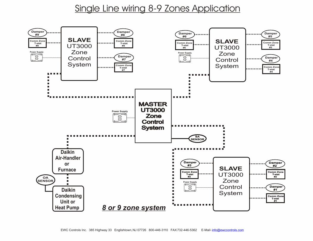
8 or 9 zone system
Power Supply
Power Supply
Power Supply
Damper #7
Comm Zone T-stat #7
Damper #9
Damper #8
SLAVEUT3000
Zone ControlSystem
Comm Zone T-stat #8
Comm Zone T-stat #9
Power Supply
Single Line wiring 8-9 Zones Application
EWC Controls Inc. 385 Highway 33 Englishtown, NJ 07726 800-446-3110 FAX 732-446-5362 E-Mail- [email protected]

ISOLATING 24vac SHORTS
Dampers not responding and TheUT3000 LED’s are off.
HVAC system not responding andUT3000 LED’s are off.
DETECTING 24vac SHORTS
Check HVAC & UT3000 system transformer supply voltage.Check HVAC & UT3000 system 24vac transformer voltage/fuse/breakers. Test all wires for Continuity, shorts to 24v Common or shorts to earth ground.Check HVAC & UT3000 system wiring for shorts and miswiring.
Check Zone system wiring for shorts/miswiring. Test wires for Continuity/Shorts.Check BIAS voltage: Data 1 to C = 2.8 & Data 2 to C = 2.2 or Data 1 to C = 1.9 & Data 2 to C = 1.3 BIAS/Term switches on the UT3000 panel and Outdoor units should be set OFF.Check HVAC equipment for faults via a Communicating T-stat & clear all faults.
Check HVAC system field wiring for proper connections, continuity & shorts.Some HVAC systems require a “System Test” prior to normal operation.Connect communicating T-stat directly to HVAC system & perform System Test.Check BIAS voltages: C to Data 1 =2.8, C to Data 2 =2.2 or C to Data 1 =1.9vdc. C to Data 2 =1.3vdc.
SOLUTIONS
T R O U B L E S H O O T I N G
LCD & LED’s function and HVAC system functions normally but
dampers do not respond.
Check damper motor wiring for proper connections.Check damper motor 24volt & 500mA Breaker. Test wires for Continuity/Shorts.Check damper motor wiring for shorts/miswiring. Test wires for Continuity/Shorts.Refer to Page 12 of the Technical Bulletin for Damper Wiring.
140mA & 500mA circuit breakers protect the UT3000 and react to a short in the Thermostat/Damper
component field wiring.
CHECK YOUR WIRING
EWC® Controls provides superior toll free Troubleshooting Support for the UT3000 when you are on the job site!
Call 1-800-446-3110 Monday - Friday 8am to 5pm EST. Otherwise call 1-732-446-3110 for information on the UT3000 and other ULTRA-ZONE® products. Visit our web site to download this Technical Bulletin and other related information at www.ewccontrols.com
When calling for Technical Support from the job-site, please have a good quality multi-meter, pocket screwdriver, and wire cutters/strippers on hand.
TECHNICAL SUPPORT
LCD & LED’s do not function and HVAC system does not respond.
Data voltages are incorrect. LCD & LED’s are responding properly and/or
Zone Thermostats are malfunctioning.
LCD & LED’s are responding properly but HVAC system is
malfunctioning. Communicating T-stat displays fault messages.
SYMPTOM
Disconnect the wire(s) from the ‘R’ terminals on the UT3000 thermostat terminal blocks , and the “C/PO/PC’’ terminals on the UT3000 damper motor terminal blocks. Restore power. If the short is no longer present, Ohm out the thermostat and damper field wiring for continuity, shorts to common and/or shorts to earth ground. Replace or repair wires as necessary. Restore power.
SOLUTIONS: Remove 24vac power from UT3000 and allow F1 circuit breaker to cool! Find and repair short(s) in damper and/or thermostat field wiring. Restore 24 vac power.
If 24vac short has occurred, 24vac will be present at the UT3000 24v Input terminals R & C; but 24vac will not be present at any Thermostat R&C.
SYMPTOM: Entire Panel or a Single Zone appears to be dead!
When the 2.5A breaker is tripped it will get hot to the touch and none of the panel LED’s will illuminate. The
LCD will also cease to function. To reset the breaker, locate the short by removing each hot wire connected to the
panel, one at a time. When the shorted wire is removed, the panel will resume normal functions. Now you must
repair or replace the shorted wire. If one or more 140mA or 500mA breakers trip, only the device(s) connected to
that block will be affected. Remove each hot wire connected to that block until the voltage is restored. Find and
repair the short before re-connecting the wires. If there is a short between the Data 1 & 2 wires or if the Data wires
are shorted to 24v or earth ground, the Communicating thermostat on that zone will alert you by displaying “Call
for Service”. If no communicating thermostat is connected and a short occurs on the 24v wires, that zone will not
function. Find and repair the short using the methods described above.
Detecting 24v shorts to common or shorts to earth ground
Forward
Back
When Troubleshooting, Simultaneously Press the Back & Forward buttons for 1 second to Bypass any Active Time Delay.
Time Delay is Active and won’t allow Heat or Cool to Function.
Copyright © 07/15/2014 EWC Controls Inc. 385 Highway 33 Englishtown, NJ 07726 800-446-3110 FAX 732-446-5362 E-Mail- [email protected]


