1
Bates XFEL Linac and Bunch Compressor Dynamics
1. Linac Layout and General Beam Parameter 2. Bunch Compressor
– System Details (RF, Magnet Chicane)– Linear bunch compressing – Wake field and CSR – Various Effects (Chirp Phase, Source..)– Further optimization and S2E Simulation
3. SummaryFuhua Wang , Dong Wang
MIT-Bates LaboratoryPresentation to MIT X-ray laser Accelerator Science Advisory
CommitteeSeptember 18-19, 2003
2
• Beam From the RF Injector: 20 ps, Charge 0.2, 1 nC.
Slice emittance 0.6,1.0 um, Slice p ~ 5KeVTwo operation mode: 0.2nC for 0.1-.2ps, 1nC for 1ps.
• Linac RF: TESLA 9cell cavity, 8 cavity cryomodule. • Two (Four bends) Bunch Compressors with adjustable
R56.• Experiment Station Energy: 1,2,4 GeVWhat make this linac different from other FEL linac driver?Seeding , HGHG operations requires high energy and timing
stability of beam, high compression ratio, extraction at several energies.
3
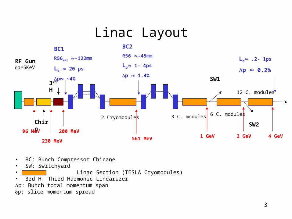
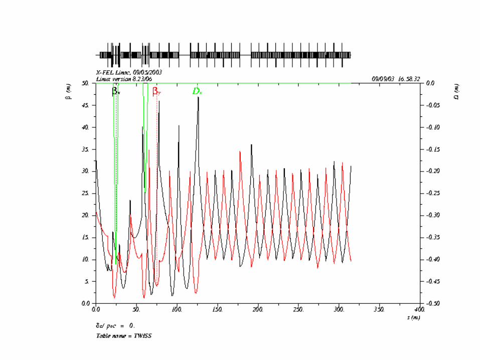
Linac Layout
• BC: Bunch Compressor Chicane• SW: Switchyard• Linac Section (TESLA Cryomodules)• 3rd H: Third Harmonic Linearizerp: Bunch total momentum spanp: slice momentum spread
BC1
R56max -122mm
Lb 20 ps
p ~4%
SW2
SW1
RF Gun p=5KeV
Chirp
3rd H
230 MeV2 GeV1 GeV561 MeV 4 GeV
96 MeV 200 MeV
BC2
R56 -45mm
Lb 1- 4ps
p 1.4%
Lb .2- 1ps
p 0.2%
2 Cryomodules 3 C. modules
12 C. modules
6 C. modules
4
5

6
7
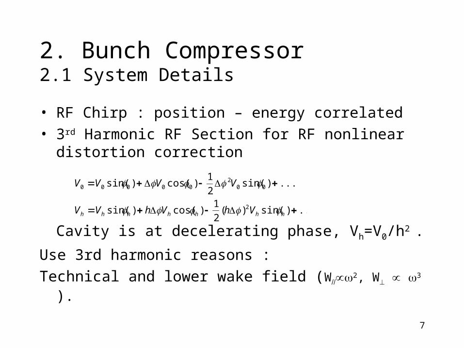
2. Bunch Compressor2.1 System Details
• RF Chirp : position – energy correlated
• 3rd Harmonic RF Section for RF nonlinear distortion correction
Cavity is at decelerating phase, Vh=V0/h2 .
Use 3rd harmonic reasons :
Technical and lower wake field (W2, W 3 ).
...)sin()(2
1)cos()sin(
...)sin(2
1)cos()sin(
2
002
00000
hhhhhhh VhVhVV
VVVV
8
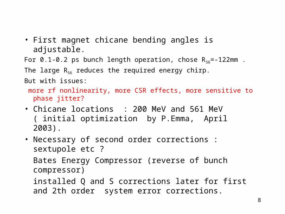
• First magnet chicane bending angles is adjustable. For 0.1-0.2 ps bunch length operation, chose R56=-122mm .
The large R56 reduces the required energy chirp.
But with issues:
more rf nonlinearity, more CSR effects, more sensitive to phase jitter?
• Chicane locations : 200 MeV and 561 MeV ( initial optimization by P.Emma, April 2003).
• Necessary of second order corrections : sextupole etc ?
Bates Energy Compressor (reverse of bunch compressor)
installed Q and S corrections later for first and 2th order system error corrections.
9
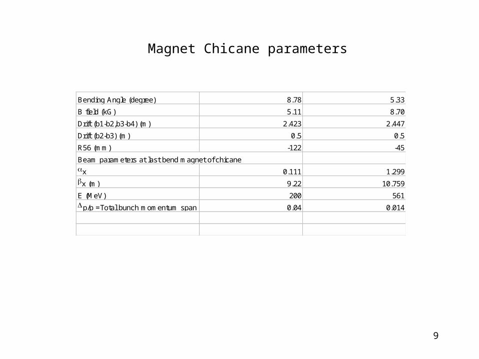
Magnet Chicane parameters
Bending Angle (degree) 8.78 5.33
B field (kG) 5.11 8.70
Drift (b1-b2,b3-b4) (m) 2.423 2.447
Drift (b2-b3) (m) 0.5 0.5
R56 (mm) -122 -45
Beam parameters at last bend magnet of chicane
x 0.111 1.299
x (m) 9.22 10.759
E (MeV) 200 561
p/p =Total bunch momentum span 0.04 0.014
10
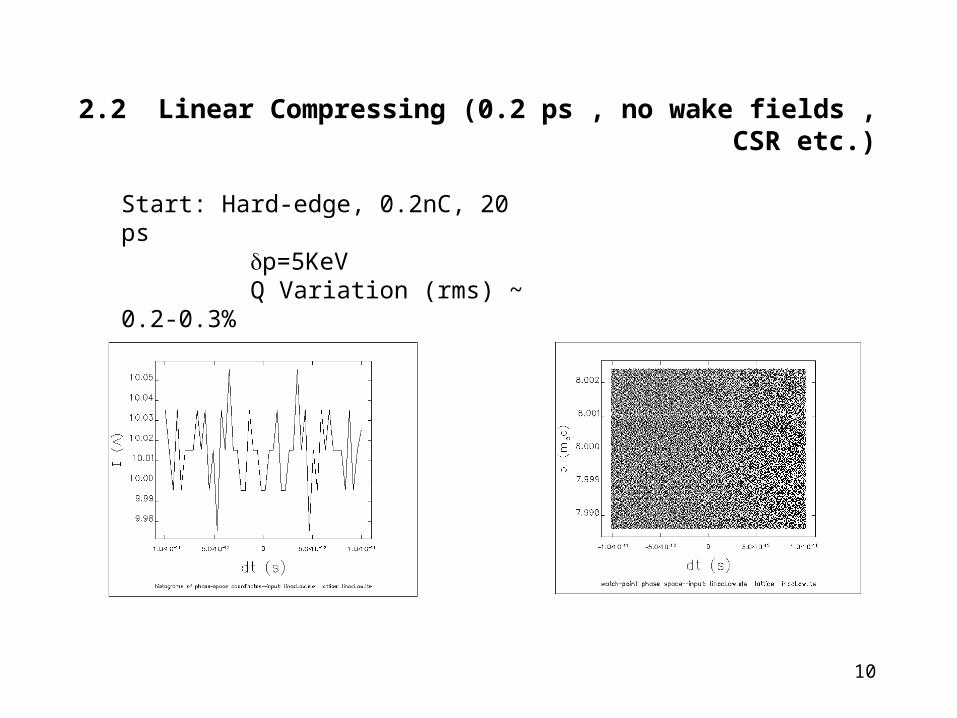
2.2 Linear Compressing (0.2 ps , no wake fields , CSR etc.)
Start: Hard-edge, 0.2nC, 20 ps p=5KeV Q Variation (rms) ~ 0.2-0.3%
11
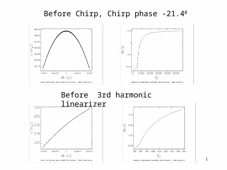
Before Chirp, Chirp phase -21.40
Before 3rd harmonic linearizer
12
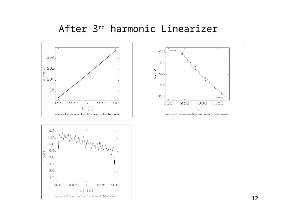
After 3rd harmonic Linearizer
13
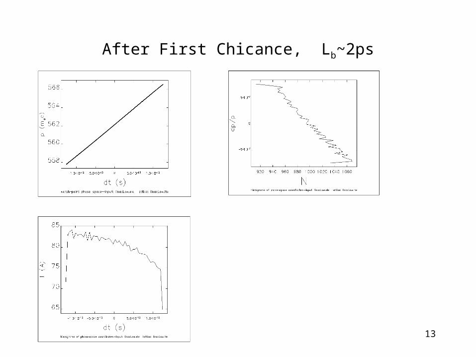
After First Chicance, Lb~2ps
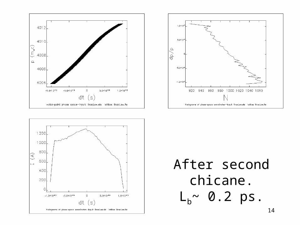
14
After second chicane.Lb~ 0.2 ps.
15
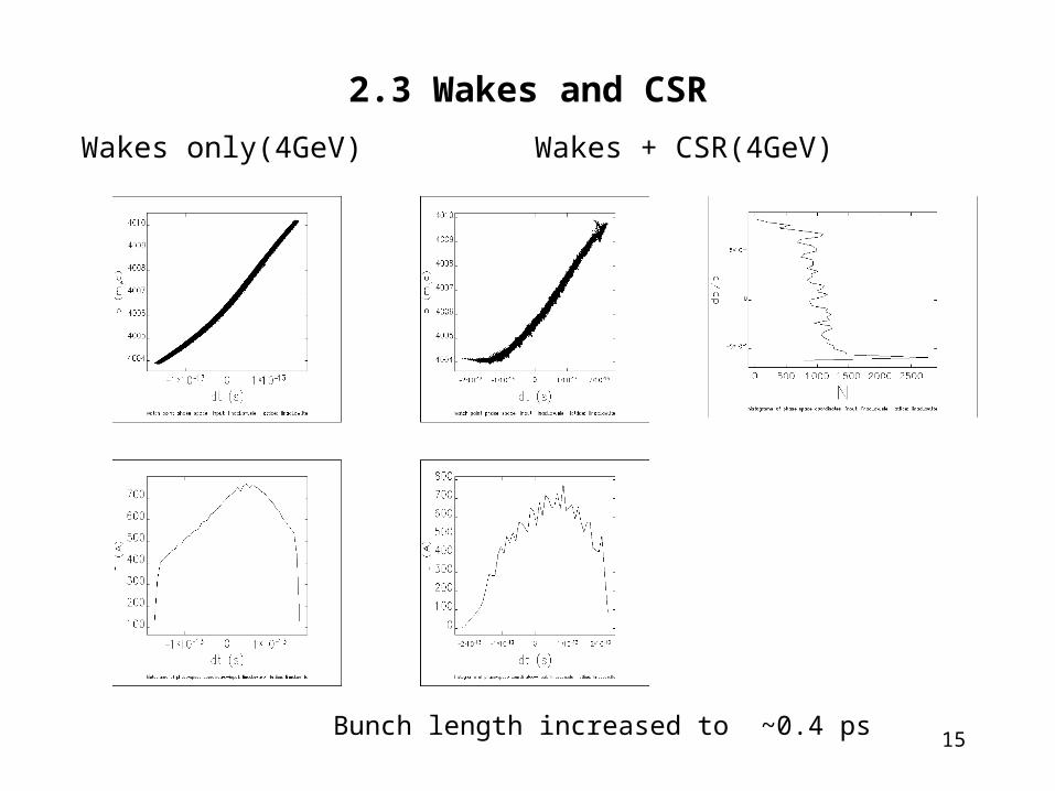
2.3 Wakes and CSR
Wakes only(4GeV) Wakes + CSR(4GeV)
Bunch length increased to ~0.4 ps
16
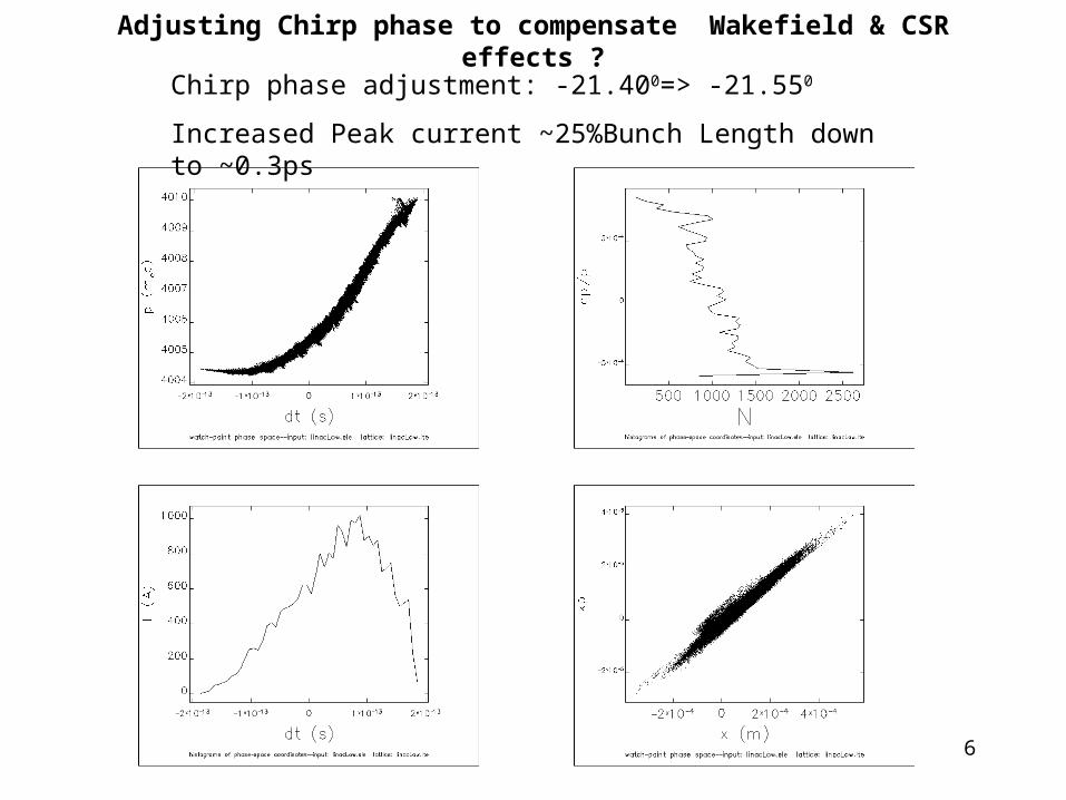
Adjusting Chirp phase to compensate Wakefield & CSR effects ?
Chirp phase adjustment: -21.400=> -21.550
Increased Peak current ~25%Bunch Length down to ~0.3ps
17
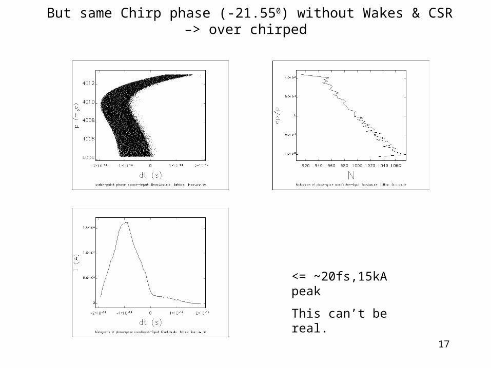
But same Chirp phase (-21.550) without Wakes & CSR –> over chirped
<= ~20fs,15kA peak
This can’t be real.
18
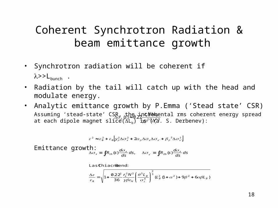
Coherent Synchrotron Radiation & beam emittance growth
• Synchrotron radiation will be coherent if
>>Lbunch .
• Radiation by the tail will catch up with the head and modulate energy.
• Analytic emittance growth by P.Emma (‘Stead state’ CSR)Assuming ‘stead-state’ CSR, the incremental rms coherent energy spread at each dipole magnet slice(Lb) is (Ya. S. Derbenev):
Emittance growth:
3/43/222.0)(
z
be LNrs
)69)1((36
22.01
:Bend ChiacneLast
)(,)(
2
2223
2
4
5222
0
2616
2'
2'
220
20
2
'
BBz
B
N
e
xx
xxxx
LLLNr
dsds
dsRds
ds
dsR
19
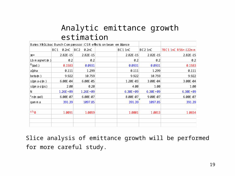
Bates Xfel-Linac Bunch Compressor : CSR effects on beam emittance
BC1 0.2nC BC2 0.2nC BC1 1nC BC2 1nC ?BC1 1nC R56=-122mm
re= 2.82E-15 2.82E-15 2.82E-15 2.82E-15 2.82E-15
Lb magnet (m) 0.2 0.2 0.2 0.2 0.2
(rad.) 0.1583 0.0931 0.0931 0.0931 0.1583
alpha 0.111 1.299 0.111 1.299 0.111
beta(m) 9.922 10.759 9.922 10.759 9.922
sigma-z(m) 6.00E-04 6.00E-05 1.20E-03 3.00E-04 3.00E-04
sigma-z(ps) 2.00 0.20 4.00 1.00 1.00
N 1.26E+09 1.26E+09 6.30E+09 6.30E+09 6.30E+09
n(mrad) 6.00E-07 6.00E-07 8.00E-07 9.00E-07 6.00E-07
gamma 391.39 1097.85 391.39 1097.85 391.39
0 1.0091 1.0059 1.0001 1.0013 1.0654
Analytic emittance growth estimation
Slice analysis of emittance growth will be performed for more careful study.
20
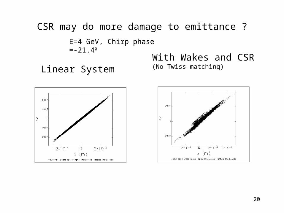
CSR may do more damage to emittance ?
Linear SystemWith Wakes and CSR(No Twiss matching)
E=4 GeV, Chirp phase =-21.40
21
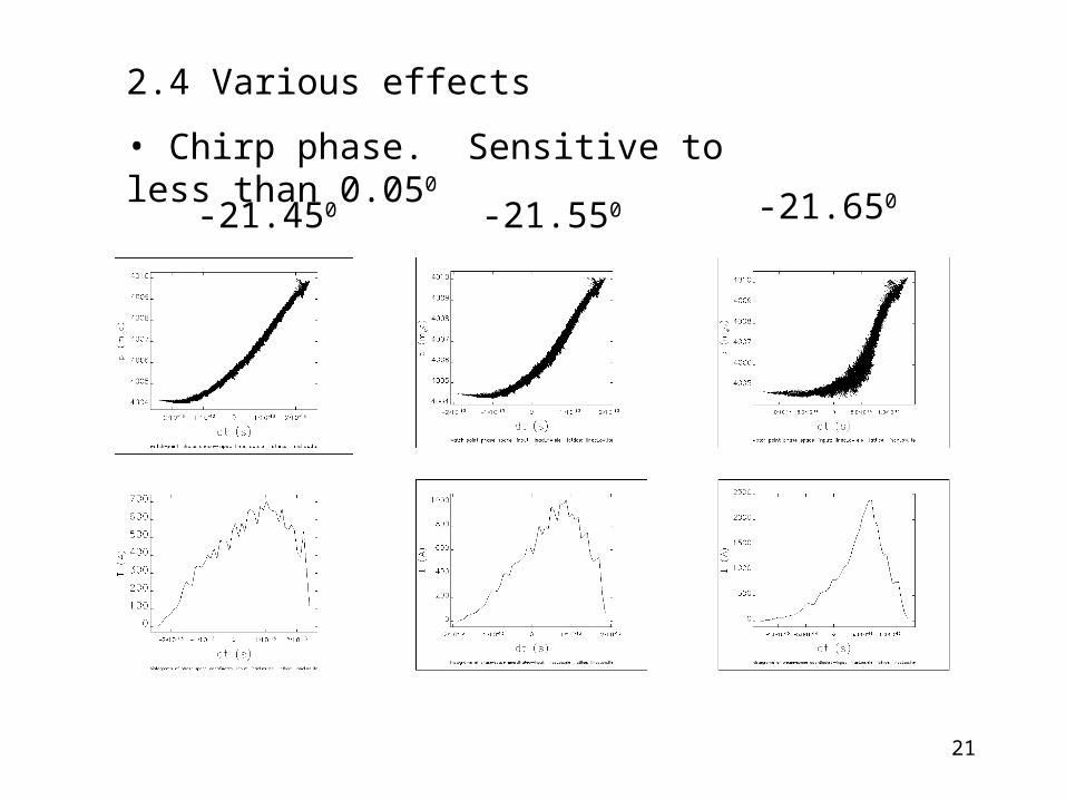
2.4 Various effects
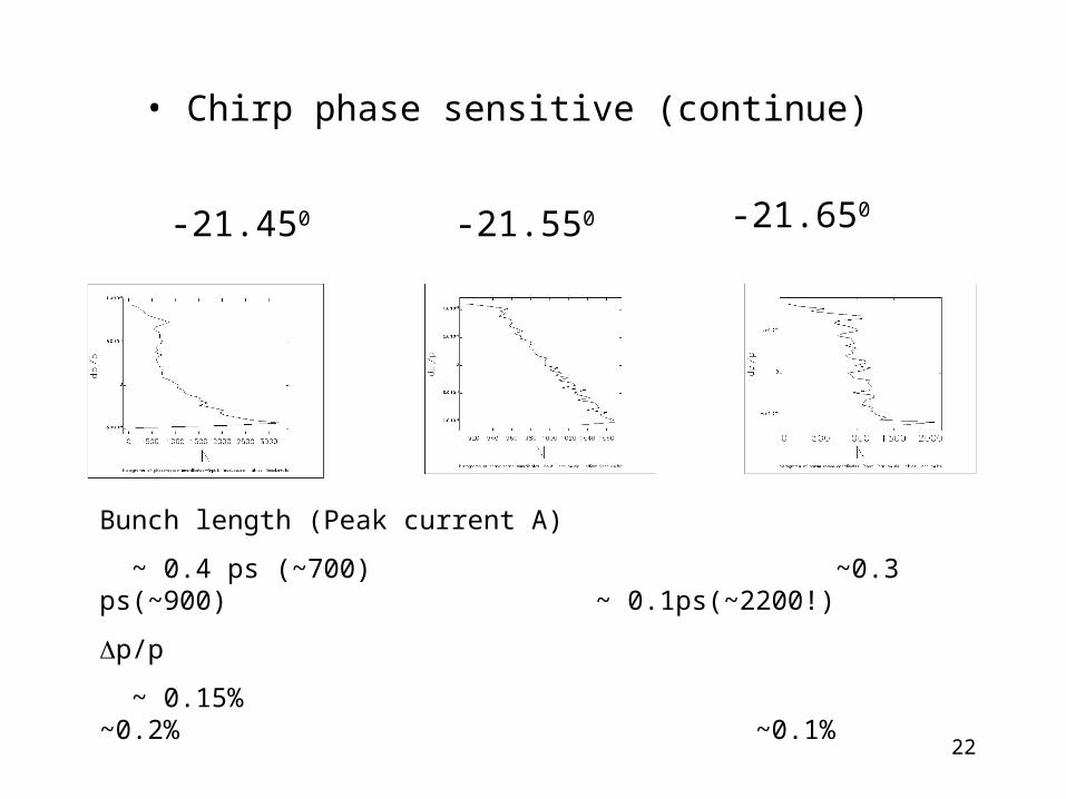
• Chirp phase. Sensitive to less than 0.050
-21.450 -21.650-21.550
22
-21.450 -21.650-21.550
• Chirp phase sensitive (continue)
Bunch length (Peak current A)
~ 0.4 ps (~700) ~0.3 ps(~900) ~ 0.1ps(~2200!)
p/p
~ 0.15% ~0.2% ~0.1%
23
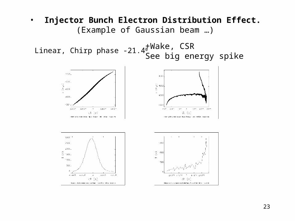
• Injector Bunch Electron Distribution Effect. (Example of Gaussian beam …)
Linear, Chirp phase -21.40 +Wake, CSRSee big energy spike
24
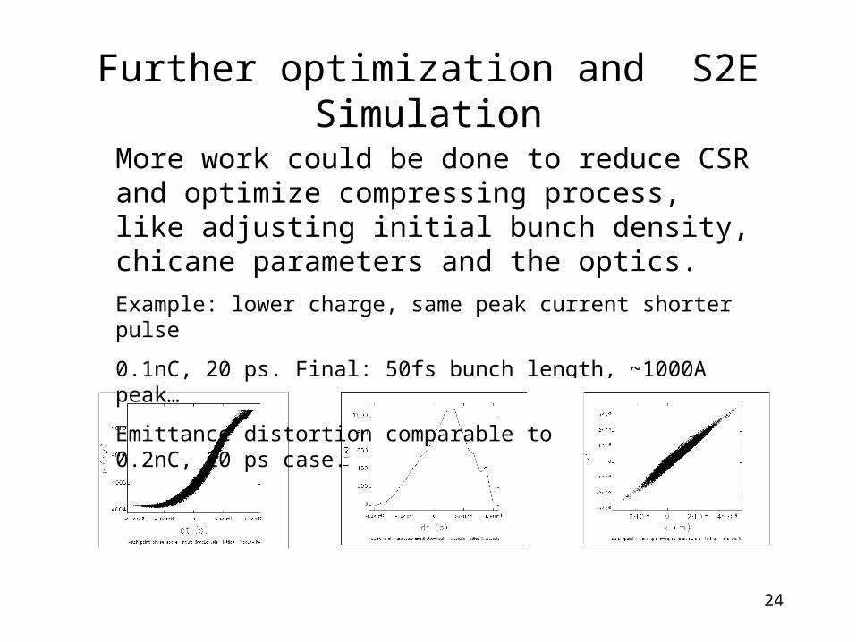
Further optimization and S2E Simulation
More work could be done to reduce CSR and optimize compressing process, like adjusting initial bunch density, chicane parameters and the optics.
Example: lower charge, same peak current shorter pulse
0.1nC, 20 ps. Final: 50fs bunch length, ~1000A peak…
Emittance distortion comparable to above mentioned 0.2nC, 20 ps case.
25
About S2E Simulation
• Start to End Simulation• Codes: PARMELA(LANL) photo injector
ELEGANT (ANL) Linac + SwitchyardGINGER(LBL) FEL
Plan: Integrate PARMELA out(beam distribution) to ELEGANT simulation. For better simulation in linac. And down to FEL get responses.
Essential for: • Design optimization. • Beam diagnostics, controls and manipulation.• System requirements (error simulations, tolerances).•
26
3. Summary
• Preliminary linac optics and bunch compressor design. Beam parameters close to design requirements.
• Tough requirements to Chirp phase.
• S2E simulation required for system optimization and define tolerances
• Much work needed to reduce nonlinear effects and there is still room to work on it!


