
1
BL AUTOMATIC BL AUTOMATIC TRANSMISSIONTRANSMISSION
((AISIN 30AISIN 30--40 40 LEiLEi))
2
1. SPECIFICATION
2. SYSTEM CONSTRUCTION
3. SYSTEM LAYOUT
4. POWER FLOW
5. COMPONENTS
6. SHIFT LOCK DEVICE INSTALLATION
7. ELECTRICAL CONTROL PARTS
8. HYDARULIC CONTROL SYSTEM
9. ELECTRONIC CONTROL
10. DIAGNOSIS
11. WIRING DIAGRAM
12. SHIFT PATTERN
CONTENTS
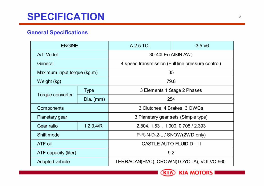
3SPECIFICATIONGeneral Specifications
A-2.5 TCI 3.5 V6
Type
Dia. (mm)
Gear ratio 1,2,3,4/R
TERRACAN(HMC), CROWN(TOYOTA), VOLVO 960
Torque converter
2.804, 1.531, 1.000, 0.705 / 2.393
P-R-N-D-2-L / SNOW(2WD only)
CASTLE AUTO FLUID D - I I
9.2
3 Elements 1 Stage 2 Phases
254
3 Clutches, 4 Brakes, 3 OWCs
3 Planetary gear sets (Simple type)
30-40LEi (AISIN AW)
4 speed transmission (Full line pressure control)
35
79.8
Shift mode
ATF oil
ATF capacity (liter)
Adapted vehicle
Weight (kg)
Components
Planetary gear
A/T Model
ENGINE
General
Maximum input torque (kg.m)

4
Engine
토크 컨버터
Input shaft
ClutchOWCBrake
Planetary gear
Output shaft
Propeller shaft
Shift lever Inhibitor switch
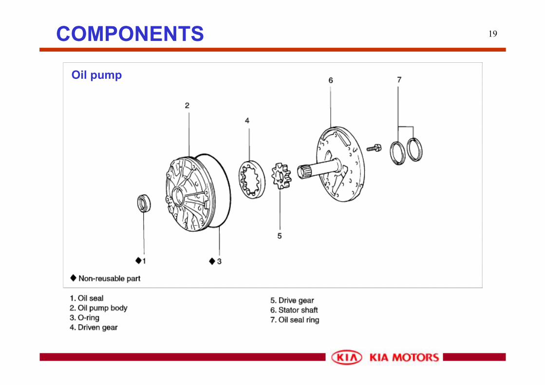
Torque converter Oil pump
Valve body
Control valves
Accumulators
Sensors & switches
SCSV A
SCSV B
DCCSV
T
C
U
Power flowHydraulic flowMechanical flowElectrical flow
Input sensor
Output sensor
PCSV
ECU
SYSTEM CONSTRUCTIONBlock Diagram

5
2
13 4
5 67 8 9
SYSTEM LAYOUT
1. Output speed sensor To detect output shaft revolution2. Neutral switch To detect "N" range(A/T) or "Neutral" range(M/T)3. Elbow (cooler out) Way-out from a cooler hose to the A/T4. Elbow (cooler in) Way-in to the cooler hose from the torque converter5. Air Breather hose For air ventilation inside transmission6. Oil temp. sensor To detect the oil temperature7. Input speed sensor To detect input shaft revolution8. Outer lever Connected to the control cable to change driving range 9. T/M wire Solenoid valves and sensors connection
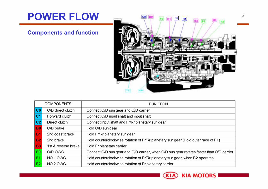
6POWER FLOWComponents and function
FUNCTIONC0 O/D direct clutch Connect O/D sun gear and O/D carrierC1 Forward clutch Connect O/D input shaft and input shaftC2 Direct clutch Connect input shaft and Fr/Rr planetary sun gearB0 O/D brake Hold O/D sun gearB1 2nd coast brake Hold Fr/Rr planetary sun gearB2 2nd brake Hold counterclockwise rotation of Fr/Rr planetary sun gear (Hold outer race of F1)B3 1st & reverse brake Hold Fr planetary carrierF0 O/D OWC Connect O/D sun gear and O/D carrier, when O/D sun gear rotates faster than O/D carrierF1 NO.1 OWC Hold counterclockwise rotation of Fr/Rr planetary sun gear, when B2 operates.F2 NO.2 OWC Hold counterclockwise rotation of Fr planetary carrier
COMPONENTS
C2 C1

7
OD OWC(F0) OWC 1(F1)
OWC 2(F2)
POWER FLOWComponents and operation
C0B0
C1
C2B1
B2B3
OD INPUT SHAFT INPUT SHAFT OUTPUT SHAFT
IN OUT

8POWER FLOWComponents and operation

9
P O S ITIO N S O LE N O ID C LU TC H B R A K E O .W .C . G E A R
S 1 S 2 S L C 0 C 1 C 2 B 0 B 1 B 2 B 3 F0 F1 F2 R A TIOP � › � ~ � ~ � › � ~ � ~ � ~ � ~ � ~ � ~ � ~ � ~ � ~ � |
R (V <7) � › � ~ � ~ � › � ~ � › � ~ � ~ � ~ � › � › � ~ � ~ 2.393R (V >=7) � › � › � ~ � › � ~ � ~ � ~ � ~ � ~ � ~ � › � ~ � ~ � |
N � › � ~ � ~ � › � ~ � ~ � ~ � ~ � ~ � ~ � ~ � ~ � ~ � |1st � › � ~ � ~ � › � › � ~ � ~ � ~ � ~ � ~ � › � ~ � ›� ~ 2.804
D 2nd � › � › � ~ � › � › � ~ � ~ � ~ � › � ~ � › � ›� ~ � ~ 1.5313rd � ~ � › � › � › � › � › � ~ � ~ � › � ~ � › � ~ � ~ 1.0004th � ~ � ~ � › � ~ � › � › � › � ~ � › � ~ � ~ � ~ � ~ 0.7051st � › � ~ � ~ � › � › � ~ � ~ � ~ � ~ � ~ � › � ~ � ›� ~ 2.804
2 2nd � › � › � ~ � › � › � ~ � ~ � › � › � ~ � › � › � ~ 1.5313rd � ~ � › � ~ � › � › � › � ~ � ~ � › � ~ � › � ~ � ~ 1.000
L 1st � › � ~ � ~ � › � › � ~ � ~ � ~ � ~ � › � › � ~ � › 2.8042nd � › � › � ~ � › � › � ~ � ~ � › � › � ~ � › � › � ~ 1.531
OFF OFFON
ON OFF OFF
OFF
OFFOFF
OFFOFF
ON ON
ON
ON
ON ON
ON ON
ON
OFF
OFF
OFF OFF
OFF OFF
OFF
OFF
OFF
OFF
ON
ON ON
ONOFF
ON OFF
ON ON
ON
ON ON
ON
ON
ON
ON
ON
ON
ON
ON ON
ON ON
ON
ON
ON
ON
ON
ON
ON
ON
ON
ON
ON
OFF
OFF
OFF
OFF
OFF
OFF
OFF
OFF
OFF
OFF OFF
OFF OFF
OFF
OFF OFF OFF
OFF OFF
OFF OFF
OFF OFF
OFF OFF
OFF OFF
OFF
OFF
OFF
OFF
OFF
OFF
OFF
OFF
OFF
OFF
OFF
OFF OFFOFF OFF
OFFOFF OFF
OFFOFF OFF OFF
OFF
OFFOFF
OFF
OFF OFF OFF OFF OFF -
OFF OFF
OFF OFF
OFF OFFOFF
OFF
OFF
OFFOFF
OFFOFFOFF
ON
ON
ON
ONON
ON
ON
ON
ON
ON
ON
ON ON
OFF
ON
ON
ON
ONON
ON
ONON
ON
ON ON
OFF
OFFOFF
OFF
OFF
ON OFF
-
-
ON OFF
ON OFF
POWER FLOWComponents and operation

10
1st /2nd gear
Direct coupling
O/D Fr / Rr
C1
4th gear
O/D Fr / Rr
C1
O/D Fr / Rr
3rd gear
C1
O/D Fr / Rr
Reverse gear
C1
Principle of each range
POWER FLOW
Speed reduction
Direct coupling
Direct coupling
Direct coupling
Direct coupling
Speed increase
Reversed rotation
1. Power flowOD input shaft OD gear set(coupling by C0) Fr/Rr
(speed reduction by F2(1st gear), by B2&F1(2nd gear))2. Engine brake- D range 1st,2nd gear: non(F2,F1 free to clockwise)- 2 range: 1st gear(non), 2nd gear(operated by B1)- L range 1st,2nd gear: operated by B1, B3
1. Power flowOD input shaft OD gear set(coupling by C0)
Fr/Rr (coupling by C1 & C2)
2. Engine brake- D & 2 range: operates
1. Power flowOD input shaft OD gear set (speed increase by B0)
Fr/Rr (coupling by C1&C2)2. Engine brake- D range: operates
1. Power flowOD input shaft OD gear set (coupling by C0)
Fr/Rr (reverse rotation by B3)2. Reverse inhibition control: C2

11POWER FLOWD range – 1st gear

12POWER FLOWD range – 2nd gear

13POWER FLOWD range – 3rd gear

14POWER FLOWD range – 4th gear

15POWER FLOWR range

16
1 2
COMPONENTS
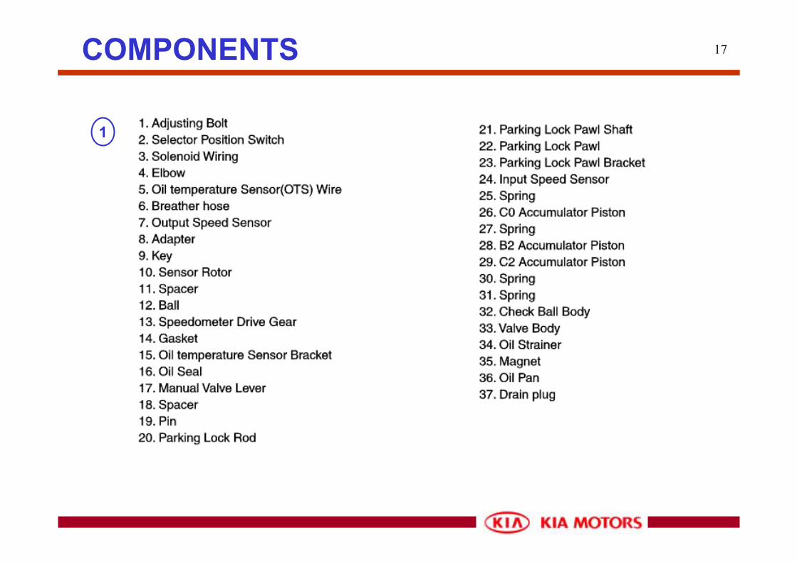
17COMPONENTS
1

18COMPONENTS
2
19
Oil pump
COMPONENTS

20
OD clutch &OD planetary gear
COMPONENTS

21
OD clutch disc (2EA)
OD clutch disc (2EA)
Input speed sensor tone
wheel (16EA)
OD sun gear
COMPONENTS
OD clutchOD clutch

22
Hub for OD brake
Input shaft
Hub for OD clutch
OD Planetary gear
OD Planetary gear
COMPONENTS
OD clutchOD clutch

23
Forward clutch
COMPONENTS

24
OD OWC (F0)OD OWC (F0)
Forward clutchForward clutch
COMPONENTS
OD OWC (F0) and Forward clutch

25
Forward clutch (5EA)
Hub for Direct clutchHub for Direct clutch
COMPONENTS
Forward clutch

26
Direct clutch
COMPONENTS

27
Direct clutchDirect clutch
Plastic washer on Direct clutch and OD brake piston
COMPONENTS
Direct clutch

28
Front planetary gear
COMPONENTS

29COMPONENTS
Front planetary sun gear & OWC 1

30
Front planetary gear
Front planetary gear
Connected to output shaft
COMPONENTS
Front planetary gear

31
Sun gear for Front planetary
gear
Sun gear for Front planetary
gear
COMPONENTS
Front planetary gear

32
Direct clutch Forward
clutch
Hub for 2nd
brakeDrum for 2nd
coast brakeDrum for 2nd
coast brake
Sun gear for rear planetary
gear
Sun gear for rear planetary
gear
OWC1 (F1)
COMPONENTS
Direct clutch & Forward clutch & OWC1

33COMPONENTS
2ND Brake

34
2ND Brake
COMPONENTS

35
2nd brake piston
Hub for LR brake
OWC2 (F2)
Rear planetary gear
Rear planetary gear
Oil holeOil hole
COMPONENTS
Rear planetary gear & 2nd brake piston

36
OD brake
COMPONENTS

37
OD brake pistonOD brake piston
COMPONENTS
OD brake

38
Low and reverse brake
COMPONENTS

39
SCSVSCSV
PCSVPCSV
DCCSVDCCSV
COMPONENTS
Valve body

40
Manual valveManual valve
PCSVPCSVDCCSVDCCSV
COMPONENTS
Valve body

41
OD direct clutch Accumulator pistons
Direct clutch Accumulator
Second brake Accumulator
OD brake Accumulator
COMPONENTS
Accumulators

42COMPONENTS
Ball and clip

43COMPONENTS
Clip

44COMPONENTS
2nd coast brake oil hole

45
Spring Roller
The Guide Pin is inserted into Shift Lock CAM.
Install direction
SHIFT LOCK DEVICE INSTALLATION

46
1. Procedure to install the lock cam. - Make sure to move shift lever to position “P” and install lock cam as figure.
2. Procedure for adjusting shift lock cable. - Check that lock cam is located in position. - Install shift lock cable in position as figure. - Temporarily install shift lock cable to A/T lever assembly as shown in figure. Securely insert cable end into fixing pin of cam.
- After checking that a portion of cable end touches cable fixing pin of P-lock cam, fix shift lock cable to A/T lever.
SHIFT LOCK DEVICE INSTALLATION

47
3. Checking that procedure for installing the shift lock is correct. - When the brake pedal is not depressed, push button of the shift lever at “P”position cannot be operated. (Shift lever cannot be shifted at the other positions from “P”). Push button can be operated at the other positions except “P”.
- When brake pedal stroke is 30 mm (with shift lever at “P” position), push buttonshould be operated without catching and shift lever can be shifted smoothly to other from “P”.
- When brake pedal is not depressed, shift lever should be shifted smoothly to “P”position from other positions.
- Brake pedal must be operated smoothly without catching at all positions. - If shift lever is shifted to “P” position, ignition key must be turned to “LOCK”position smoothly.
SHIFT LOCK DEVICE INSTALLATION

48ELECTRICAL CONTROL PARTSSystem Description
1. Neutral start switch
2. Output speed sensor
3. Input speed sensor(C0)
4. Oil temperature sensor
5. SCSV 1, SCSV 2
6. Line pressure control sol.
7. Lock-up solenoid

49ELECTRICAL CONTROL PARTSEach electrical parts
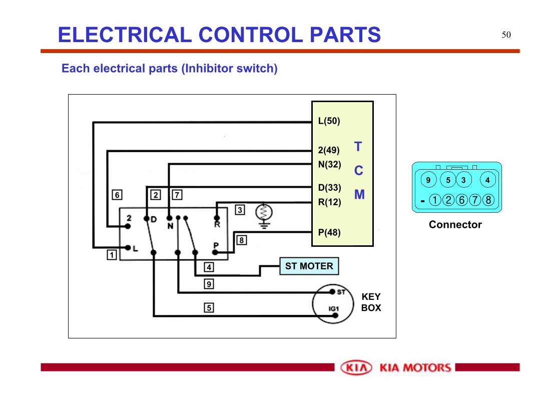
• No input signal: ‘D’ range control
• Multi input signals: Priority of D-2-L-R-N-P
50
4359
- ①②⑥⑦⑧
KEY BOX
ST MOTER
L(50)
2(49)N(32)
D(33)R(12)
P(48)
T
C
M
1
26 7
3
8
4
9
5
ELECTRICAL CONTROL PARTSEach electrical parts (Inhibitor switch)
Connector

51ELECTRICAL CONTROL PARTSEach electrical parts

52ELECTRICAL CONTROL PARTSEach electrical parts (Input speed sensor, C0)
- To detect input shaft speed
- Data for shift control (Judge the beginning or the end of 4th gear shifting)
- Detect if 4th gear is engaged or not
- 0 RPM at 4th gear C0 (no operation)
C0 rev.>500 rpm:recognition to be shifted to 3rd gear
C0 rev.<500 rpm: recognition to be shifted to 4th gear
Connector
NC0-GNC0 TCM
(520)
(428)
(1027)
(846)
680
560
400
500
600
700
800
900
1000
1100
-40 0 40 80 120Temperature / degree C
Res
ista
nce
/ ohm
150
560-680 ohm (20 degrees Celsius)

53ELECTRICAL CONTROL PARTSEach electrical parts (Output speed sensor)
Resistance: 387 –473 ohm (20 degrees Celsius)
Output speed sensor
(362)
(715)
(584)
380
480
(295)250
350
450
550
650
750
-40 0 40 80 120Temperature / degree C
Res
ista
nce
/ ohm
150
473
387Connector
SP-GSP TCM
- To detect output shaft speed
- Data for shift control
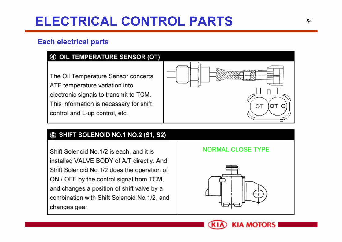
54ELECTRICAL CONTROL PARTSEach electrical parts
SHIFT SOLENOID NO.1 NO.2 (S1, S2)

55ELECTRICAL CONTROL PARTSEach electrical parts (Oil temperature sensor)
0 degree C 1,884 - 2,290 ohm
160 degree C 19.2 - 22.2 ohm
Connector
OT-GOT TCM
- To detect oil temperature
- Data for high or low oil temperature shift control
- 200 degrees Celsius when short or open No lock-up control
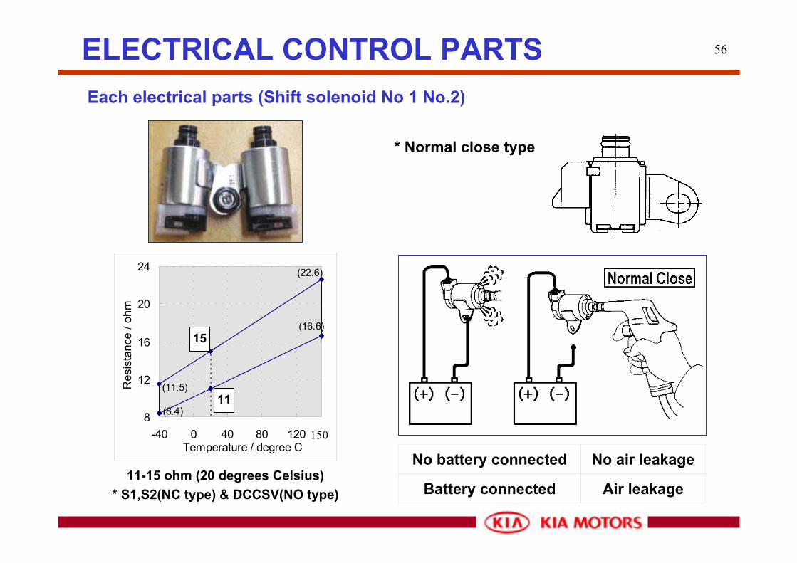
56ELECTRICAL CONTROL PARTSEach electrical parts (Shift solenoid No 1 No.2)
* Normal close type
(11.5)
(8.4)
(22.6)
(16.6)
11
15
8
12
16
20
24
-40 0 40 80 120Temperature / degree C
Res
ista
nce
/ ohm
150
11-15 ohm (20 degrees Celsius)* S1,S2(NC type) & DCCSV(NO type)
No battery connected No air leakage
Battery connected Air leakage
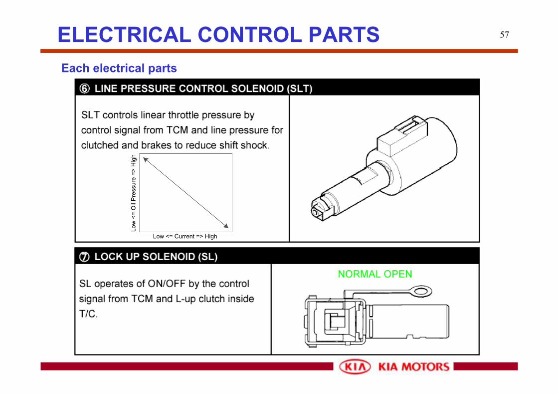
57ELECTRICAL CONTROL PARTSEach electrical parts
Low <= Current => High
Low
<=
Oil
Pres
sure
=>
Hig
h

58ELECTRICAL CONTROL PARTSEach electrical parts (Line pressure control solenoid valve)
Resistance: 3.3 - 3.7 ohm (20 degrees Celsius)
3.7
3.3
(5.59)
(4.99)
(2.52)
(2.83)
3
4
5
6
7
8
9
-40 0 40 80 120Temperature/걥
Res
ista
nce/ 꺐
Res
ista
nce/
ohm
Temperature (Celsius)
ConnectorSLT-GSLT TCM
IDLE STALL
D 3.7 ~ 4.3 8.1 ~ 9.0
R 6.2 ~ 7.2 15.6 ~ 19.0
LINE PRESSURE (kg/cm2)SHIFTRANGE

59ELECTRICAL CONTROL PARTSEach electrical parts (Line pressure control solenoid valve)
- Linear control of applied oil pressure
According to the amount of applying current from the TCM to the line pressure control solenoid coil, accumulator control pressure is managed resulting in smooth engagement of clutches and brakes.
According to the TPS opening angle, it controls the applying oil pressure to the primary regulator valve and generates proper line pressure which matches engine load.

60ELECTRICAL CONTROL PARTSEach electrical parts (Lock-up solenoid valve or DCCSV)
According to each L-up shift schedule, TCM sends signals to the Lock-up solenoid valve which operates ON/OFF control “L-up control” on the basis of the vehicle speed and the throttle opening.
■ Solenoid Type: NO(Normal Open)
* HP/H1(HMC), BL NO Type
Enterprise Duty Type
03-Model NC Type
■ Hydraulic flow
Solenoid modulator valve Lock-up solenoid Solenoid relay valve Lock-up relay valve Lock-up control valve
(11.5)
(8.4)
(22.6)
(16.6)
11
15
8
12
16
20
24
-40 0 40 80 120Temperature / degree C
Res
ista
nce
/ ohm
150
11-15 ohm (20 degrees Celsius)
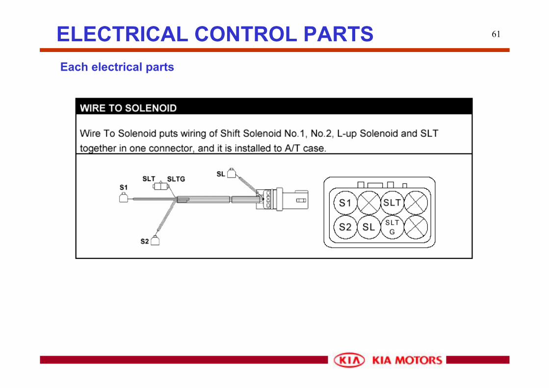
61ELECTRICAL CONTROL PARTSEach electrical parts

62
- Throttle opening (%) signal
- ECM→TCM as CAN data
ELECTRONIC CONTROLTPS (Throttle Position Sensor) signal
TPS outputTCM30
31
25
ECMTPS CAN line

63ELECTRONIC CONTROLWater Temperature signal
- Water Temperature (Celsius) signal
- ECM→TCM as CAN data
WT outputTCM30
31
25
ECMWT CAN line

64
OIL COOLER
VOLTAGE
OILPRESSURE
REASO-NABLE OILPRESS.
LUBLICATION
OPERATION
SHIFT VALVECONTROL VALVE
SENDOIL
OIL PUMP
RGLTR VALVEMDLTR VALVE
SOL
TCM
PLNTRY GEAR
CLUTCH¥BRAKE
OIL PAN
T/C
Hydraulic system block diagram•Oil pump•Valve body assembly•Sol. Valve•Accumulator•Oil path
HYDRAULIC CONTROL SYSTEM
Based on the hydraulic pressure created by the oil pump, TCM sends signals to solenoid and hydraulic control system governs the hydraulic pressure acting on thetorque converter, plane-tary gear, clutches and brakes in accordance with the vehicle driving conditions.
Constructions

65
Oil pump
HYDRAULIC CONTROL SYSTEM
Operated by the impeller hub inside Torque converter, it generates oil pressure for operating components as well as lubricating planetary gear set.
Valve bodyConsists of an upper body and a lower body. It controls hydraulic pressure that applies to operating components as well as changes oil paths inside valve body.

66
Manual valve
HYDRAULIC CONTROL SYSTEM
Connected to a shift lever, it changes oil path according to the shift lever position, P-R-N-D-2-L.
Primary regulator valve
Using the throttle pressure, Primary regulator valve processes the pressure from the oil pump and generates proper line pressure in accordance with engine load. If the primary regulator valve is abnormal, shift shock or disc slip occurs.
* Line pressure: Basic operating pressure to engage all the clutches and brakes.

67
C1 orifice control valve
HYDRAULIC CONTROL SYSTEM
Line pressure from manual valve applies to C1. At the same time lock-up control pressure also applies to the other side of the spool valve inside it. Therefore the output pressure to forward clutch via this valve changes.
Secondary regulator valve
It keeps converter pressure, lubrication and cooler pressure steady. If the converter pressure increases, it drains, if the converter pressure decreases, then it stops the drain. Therefore the converter pressure can be controlled stably.

68
SCSV-A, B
HYDRAULIC CONTROL SYSTEM
SCSC-A & B controls 1-2, 2-3, 3-4 shift valve by ON or OFF signal from TCM.Line pressure applies to the SCSV-A at all the forward driving ranges(D,2,L) and to the SCSV-B at all ranges(P,R,N,D,2,L).
* Sol. Type: NC (Normal close)When ON, it is open line pressure toshift valve drains
* Resistance: 11~15 ohm (20 degrees Cels.)
ON ON OFF OFF
OFF ON ON OFF
P Parking - - -
R Reverse - - -
N Neutral - - -
D 1st 2nd 3rd 4th
2 1st 2nd 3rd 3rd
L 1st 2nd 2nd 1st
SCSV-A
SCSV-B
Shift range

69
1-2 Shift valve
HYDRAULIC CONTROL SYSTEM
1-2 shift valve performs 1st - 2nd gear shift by SCSV-B ON/OFF.
* SCSV-B ON:Pressure at ‘A’ releases Spool moves upward Pressure to B2 is applied 2nd gear
* SCSV-B OFF: Hydraulic pressure applied to ‘A’ Spool moves downward B2 pressure is cut 1st gear
* At 4th gear, even the SCSV-B is OFF, the spool moves upward because of the 2-3 shift valve line pressure: Pressure is applied to B2

70
2-3 Shift valve
HYDRAULIC CONTROL SYSTEM
2-3 shift valve performs 2nd - 3rd gear shift by SCSV-A ON/OFF.
* SCSV-A ON:Pressure at ‘A’ releases Spool moves upward C2 pressure is cut 2nd gear
* SCSV-A OFF: Hydraulic pressure applied to ‘A’ Spool moves downward Pressure to C2 is applied 3rd gear
* At ‘L’ range, the spool moves upward because the line pressure from a manual valve applies to ‘B’: 3rd gear is impossible

71
3-4 Shift valve
HYDRAULIC CONTROL SYSTEM
3-4 shift valve performs 3rd - 4th gear shift by SCSV-B ON/OFF.
* SCSV-B ON:Pressure at ‘A’ releases Spool moves upward B0 pressure is cut 3rd gear
* SCSV-B OFF: Hydraulic pressure applied to ‘A’ Spool moves downward Pressure to B0 is applied 4th gear
* At ‘2’, ‘L’ range, the spool moves upward because the line pressure from a 2-3 shift valve applies to ‘B’: 4th gear is impossible

72
Accumulators
HYDRAULIC CONTROL SYSTEM
Hydraulic circuit of accumulator, of which one side is installed in the TM case and the other side faces the valve body, is connected with hydraulic circuit to Clutches, Brakes in parallel. It functions as a damper to lessen the engaging shock of Clutches and Brakes.That is,accumulator functions as a damper until the accumulator back pressure and spring force that applies on the back side of the piston reaches the line pressure of the other side. If the line pressure exceeds the accumulator back pressure and spring force, accumulator just functions as oil path.
30-Model has 5 accumulators (C0, C1, C2, B0, B2), one of them is installed inside a valve body and the others are located in the TM case.

73
a
c
b
c"c'
t1
t2
t3
b"
Line
pre
ssur
e
(PL)
Time(t)
X
Y
Z :Without Accum.X
Accum. Spring loadY > Z
PL Out
Spring
Back pressure
PL In
Piston
Orifice
Accumulators
HYDRAULIC CONTROL SYSTEM
Accum. Operating tim ing
C0 4 → 3
C1 N → D
C2 2 → 3
B0 3 → 4
B2 1 → 2
Function

74ELECTRONIC CONTROLBlock Diagram
A/T range switch-P
ROM
RAM
Micro-Processor
TCMA/T range switch-R
A/T range switch-N
A/T range switch-D
A/T range switch-2
A/T range switch-L
Input speed signal
Output speed signal
Oil Temp. signal
O/D off signal
4WD Low signal
Brake signal
CAN Data (to TCM)
PCSV
SCSV-A
SCSV-B
DCCSV(Lock-up sol.)
K-Line
O/D off Lamp
SNOW Lamp(2WD)
CAN Data (to ECM)
SNOW signal(2WD)
Input Output

75
■ Shift decision factors
- TPS(CAN data), Output + Input speed(serial data)
■ Driving control ( : Up/Down Shift, : Only Down Shift)
- Normal & Hot Mode D : 1↔2↔3↔4 2 : 1↔2←3 L : 1←2
- L4 Mode D : 1↔2↔3 2 : 1↔2←3 L : 1←2
- Snow Mode D : 2↔3↔4 2 : 1↔2←3 L : 1←2
ELECTRONIC CONTROLShift control
Gear SCSV No.1 SCSV No.2
1st ON OFF
2nd ON ON
3rd OFF ON
4th OFF OFF
76
■ Purpose- Low fuel consumption, NVH, (Emission) improvement
■ Operating condition- Brake switch: Off- Throttle opening: 12% ↑(2.5 DSL), 6.5% ↑(3.5 GSL)- Coolant temperature: -100℃ ↑
■ Control inhibition- Brake Switch: ON- Throttle opening: 9% ↓(2.5 DSL), 5% ↓(3.5 GSL)- Low coolant temperature: -100℃↓
- 4WD LOW mode
ELECTRONIC CONTROLDamper clutch control

77ELECTRONIC CONTROLEngine torque reduction(ETR) and line pressure control (LPC)
Engine torque reduction control improves shift quality due to sending torque reduction request signal from TCM to ECM and reducing engine torque while shifting “N” to “D”, “N”to ”R” as well as shifting 1 2 3 4.
* TCM have no information of real (current) engine torque, but through the calibration work at each condition in the actual vehicle for up- and down-shifts, the TCM determines the value by how much the engine torque has to be reduced.
Line pressure control improves shift quality due to controllable line pressure while shifting “N” to “D”, “N” to ”R” as well as shifting 1 2 3 4.
* Controlled line pressure is a mapping data which changes according to the current gear position, TPS value, oil temperature.

78ELECTRONIC CONTROLEngine torque reduction(ETR) and line pressure control (LPC)
ETR

79ELECTRONIC CONTROLReverse inhibition control
■ Purpose- To prevent engaging “Reverse” gear while D R shift (Neutral by C2)
■ Operating condition- D R shift- Output speed >= H/S
■ Control- C2 pressure drains, when output speed >= H/S
■ Control inhibition- Output speed < R/S
* High Speed(H/S): 2.5 DSL: 350 rpm(11km/h), 3.5GSL: 400 rpm(11km/h)* Reset Speed(R/S): 2.5 DSL: 300 rpm(9km/h), 3.5GSL: 325 rpm(9km/h)
D R
If,No > H/SThen ‘N’
If,No < R/SThen ‘R’
No

80ELECTRONIC CONTROLEngine over-run inhibition control
■ Purpose- To prevent engine over-run by turning the O/D OFF switch accidentally “ON” at high vehicle speed
■ Operating condition- Driving at 4th speed- O/D OFF switch: ON- Vehicle speed >= wot_SH43
■ Control inhibition- O/D OFF switch: OFF- Vehicle speed < wot_SH43 - Below 4 3 shift point
* wot_43SH - 2.5 DSL: 4200 rpm(136 km/h), 3.5GSL: 5000 rpm(145 km/h)
4→3
wot_SH43
Vehicle speed
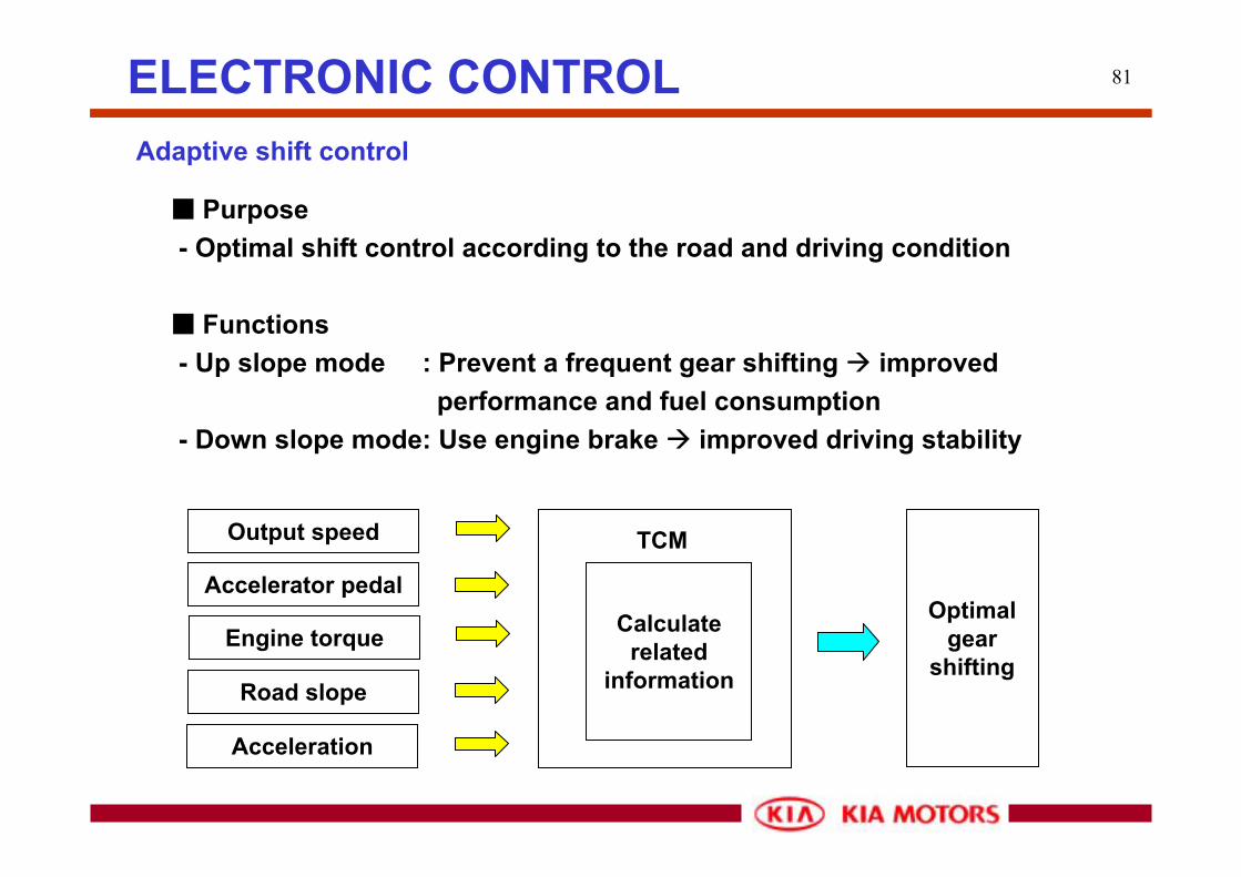
81ELECTRONIC CONTROLAdaptive shift control
■ Purpose- Optimal shift control according to the road and driving condition
■ Functions- Up slope mode : Prevent a frequent gear shifting improved
performance and fuel consumption- Down slope mode: Use engine brake improved driving stability
Output speed
Accelerator pedal
Engine torque
Road slope
Acceleration
TCM
Calculate related
information
Optimal gear
shifting

82ELECTRONIC CONTROLAdaptive shift control (Up slope mode)
Accelerator pedal is off while sloping upward, gear shifts up resulting in poor acceleration. Up slope mode prevents up-shifting at the moment to maintain the driving force during acceleration or escaping corner.According to the slope angle, there are two modes, Up slope1 and Up slope 2.
A
B
4th gear3rd gear
2nd gear
Up slope 2
Up slope 1

83ELECTRONIC CONTROLAdaptive shift control (Down slope mode)
While driving down hill, engine brake operates automatically according to accelerator position and braking condition at a certain slope degree.
4th gear3rd gear
4th gear
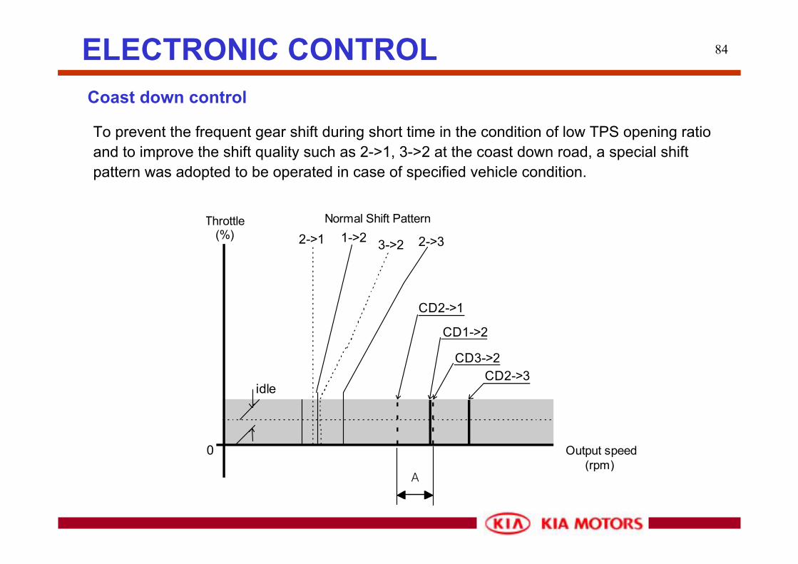
84ELECTRONIC CONTROLCoast down control
To prevent the frequent gear shift during short time in the condition of low TPS opening ratio and to improve the shift quality such as 2->1, 3->2 at the coast down road, a special shift pattern was adopted to be operated in case of specified vehicle condition.
CD2->1
CD1->2
CD3->2CD2->3
Throttle(%)
Output speed(rpm)
1->2 2->33->22->1
0
idle
Normal Shift Pattern
A
85ELECTRONIC CONTROL
■ Coast down control start condition
- Brake switch is N (When the foot brake is depressed)
- Engine is idle (When the accelerator pedal is not depressed)
- D or 2 range
■ Coast down control cancellation condition
- After 1 second since the brake switch is OFF (To prevent hysteresis)
- TPS > 0% (When the accelerator pedal is depressed)
Coast down control

86ELECTRONIC CONTROL
When ATF temperature abnormally rises (more than 135 degrees Celsius), TCM changes shift pattern automatically to avoid ATF temperature increase. This kind of Hot mode situation can happen when the vehicle is moving up on a steep slope. TCM changes the shift pattern as a high ATF shift pattern extending a low gear range but it does not operating damper clutch. Engaging damper clutch engagement can rapidly drop down ATF temperature but it reveals inferior drivability.
* In case of Terracan(HMC) which uses same AT model, damper clutch can operate from 2nd gear.
- ATF Temp.>= 135 degrees Celsius High ATF Temp. shift pattern- ATF Temp. <= 120 degrees Celsius Normal shift pattern
High ATF temperature control

87DIAGNOSISStall test
■ Purpose- To check the slip of components and overall performance of the
transmission
■ Caution- Never longer than 5 seconds at a time- Take at least one minute idle time in neutral before one more test
■ Stall RPM- 2.5 TCI: 2420 +- 150 RPM- 3.5 GSL: 2520 RPM
■ Test result- Over the normal RPM: Slip of components, less line pressure- Below the normal RPM: ATF oversupply, lack of engine power

88DIAGNOSISStall test
■ Test result
Possible causeLine pressure too lowOD clutch slippingOD one-way clutch not operating properlyForward clutch slippingRear one-way clutch not operating properlyLine pressure too lowOD clutch slippingOD one-way clutch not operating properlyDirect clutch slippingLow & reverse clutch slippingLine pressure too lowOD clutch slippingOD one-way clutch not operating properlyEngine out of tuneSlipping of one way clutch within torque converter
In "D" and "R" range
In "D" range only
In "R" range only
Abovestandard
Below standard
Condition

89DIAGNOSISLine pressure test
■ Test result
Possible causeDefective or stuck the throttle valveDefective or stuck the regulator valveDefective the oil pumpOD clutch slippingFluid leakage in the "D" range line pressurehydarulic circuitForward clutch slippingOD clutch slippingFluid leakage in the "R" range line pressurehydarulic circuitDirect clutch slippingDefective low & reverse brakeDefective or stuck the throttle valveDefective or stuck the regulator valve
In "D" and "R" ranges
In "D" range only
In "R" range only
Belowstandard
Excessive line pressure at idle
Condition
Idle Stall
D 4.0 - 4.6 11.7 - 13.2
R 6.2 - 7.2 15.6 - 19.0
Line Pressure (kg/cm2)Shiftposition

90DIAGNOSISWarning lamp & Data Link Connector(DLC)
Waning lamp : DOM/GEN Only※ OBD area : MIL Lamp
DLC (20 PIN) : Engine compartmentDLC (16PIN) : Inside Cabin
■ Trouble codes and service data display on a HI-SCAN (PRO)■ Failure warning: O/D OFF lamp, MIL (OBD area)■ 2 DLCs are supplied

91DIAGNOSIS
PIN NAME FUNCTIONA Fuel pump Fuel pump is operated under IG ONB IG1 Key switch IG1 powerC Discretionary -D Condenser fan Condenser fan is operated in case of groundE RKE coding Data send and receivingF Air bag Data send and receivingG Flash power Data re-writeH ABS Data send and receivingI Discretionary -J Spark plug adjustment -K K-line Data send and receivingL Discretionary -M EAT fail Display of TCM fail codeN EAT test TCM check in case of groundO IG- For RPM checkP Engine fail Display of Engine fail codeQ engine test ECM check in case of groundR GND -S GND -T B+ Battery power
20 Pin DLC connector
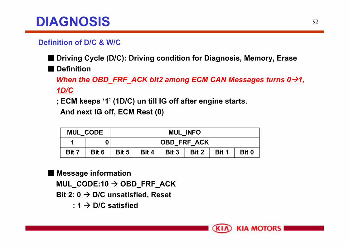
92DIAGNOSISDefinition of D/C & W/C
■ Driving Cycle (D/C): Driving condition for Diagnosis, Memory, Erase■ Definition
When the OBD_FRF_ACK bit2 among ECM CAN Messages turns 0 1, 1D/C; ECM keeps ‘1’ (1D/C) un till IG off after engine starts. And next IG off, ECM Rest (0)
1 0Bit 7 Bit 6 Bit 5 Bit 4 Bit 3 Bit 2 Bit 1 Bit 0
MUL_CODE MUL_INFOOBD_FRF_ACK
■ Message informationMUL_CODE:10 OBD_FRF_ACKBit 2: 0 D/C unsatisfied, Reset
: 1 D/C satisfied

93DIAGNOSISDefinition of D/C & W/C
■ Warm-up Cycle (W/C): Driving condition for OBD■ Definition
When the OBD_FRF_ACK bit0 among ECM CAN Messages turns 0 1, 1W/C; ECM keeps ‘1’ (1D/C) if all the conditions below are satisfied until IG off after engine starts. - Coolant temperature >= 71 degrees Celsius, and it should be
4 degree Celsius higher than the previous temperature.
1 0Bit 7 Bit 6 Bit 5 Bit 4 Bit 3 Bit 2 Bit 1 Bit 0
MUL_CODE MUL_INFOOBD_FRF_ACK
■ Message informationMUL_CODE:10 OBD_FRF_ACKBit 0: 0 W/C unsatisfied, Reset
: 1 W/C satisfied

94
■ 2 Driving cycle detection: DTC is duplicated in case same failure is detected at least 2 consecutive driving cycles.
2
5
IG OFF => ON
PXXXX
3
4
1
ON
OFF
ACCON
OFF
ACC
DIAGNOSIS2 Consecutive Driving cycles
Tester detects one failure (one driving cycle)
Tester detects failure again (2 driving cycle)
IG OFF => ON
Symptom simulation test
Perform the symptom simulation test again
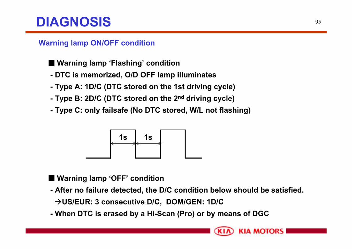
95DIAGNOSISWarning lamp ON/OFF condition
■ Warning lamp ‘Flashing’ condition- DTC is memorized, O/D OFF lamp illuminates- Type A: 1D/C (DTC stored on the 1st driving cycle) - Type B: 2D/C (DTC stored on the 2nd driving cycle)- Type C: only failsafe (No DTC stored, W/L not flashing)
1s 1s
■ Warning lamp ‘OFF’ condition- After no failure detected, the D/C condition below should be satisfied.
US/EUR: 3 consecutive D/C, DOM/GEN: 1D/C- When DTC is erased by a Hi-Scan (Pro) or by means of DGC
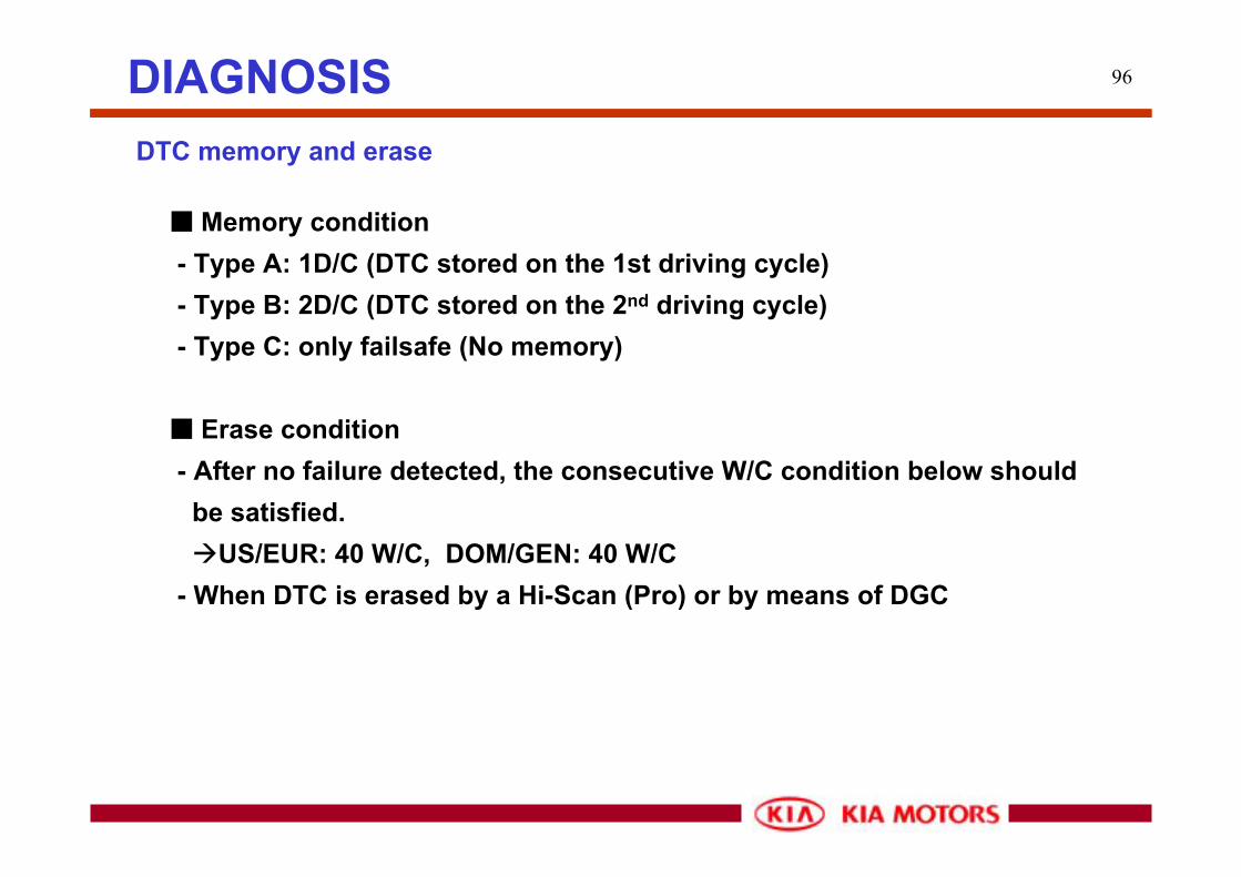
96DIAGNOSISDTC memory and erase
■ Memory condition- Type A: 1D/C (DTC stored on the 1st driving cycle) - Type B: 2D/C (DTC stored on the 2nd driving cycle)- Type C: only failsafe (No memory)
■ Erase condition- After no failure detected, the consecutive W/C condition below should
be satisfied.US/EUR: 40 W/C, DOM/GEN: 40 W/C
- When DTC is erased by a Hi-Scan (Pro) or by means of DGC

97
How to check the Fail-code by means of DGI/DGC
1) Let the PIN No. 11 of DLC ground.2) O/D OFF lamp will be flashing several seconds after O/D OFF lamp turns on.3) For the clear of Fail-code, let the PIN No. 3 of DLC ground over than 5 sec.
[Data Link Connector]
1 2 3 4 5
9 10 11 12
6 7 8
13 14 15 16
DTC clear switch
Diagnosis switch
K-line
DIAGNOSIS
98
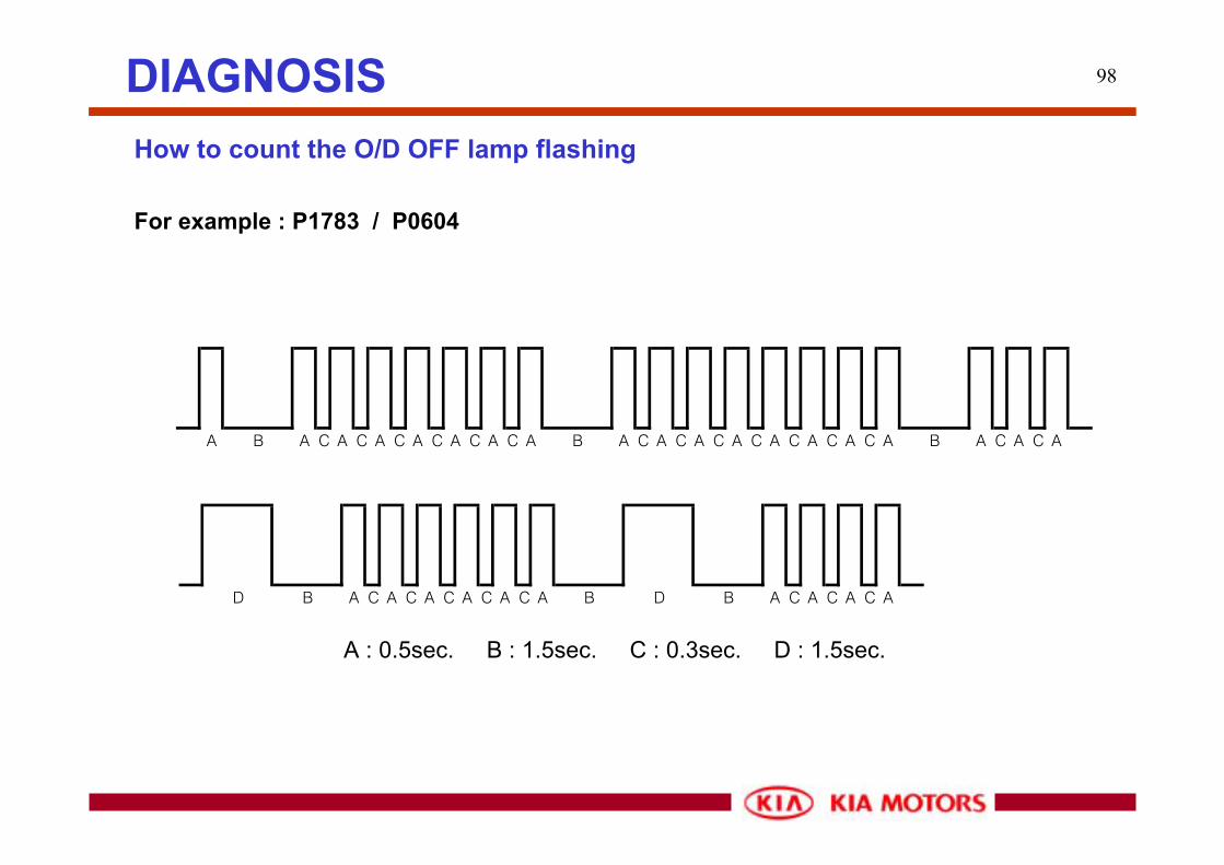
How to count the O/D OFF lamp flashing
For example : P1783 / P0604
A B A C A C A C A C A C A C A B A C A C A C A C A C A C A C A B A C A C A
D B A C A C A C A C A C A B D B A C A C A C A
A : 0.5sec. B : 1.5sec. C : 0.3sec. D : 1.5sec.
DIAGNOSIS

99
MIL Request
DIAGNOSIS
■ MIL: On-board warning lamp for OBD-II, EOBD Emission regulation
■ MIL ON condition- When DTC is memorized in TCM,
; TCU CAN Message, TCU_OBD Bit 2 sets 0 1
Bit 3 Bit 2 Bit 1 Bit 0MIL blinking MIL on freeze frame readiness
■ MIL OFF condition- After no failure detected, the D/C condition below should be satisfied.
US/EUR: 3 consecutive D/C - When DTC is erased by a Hi-Scan (Pro) or by means of DGC
100
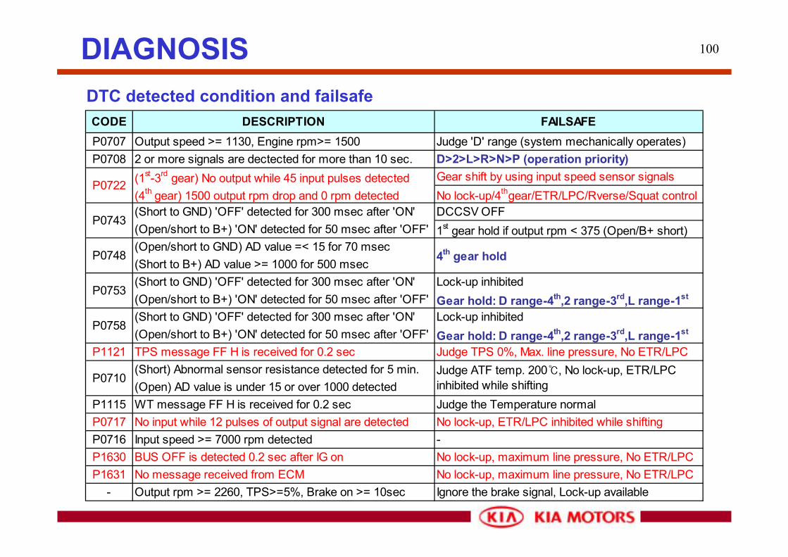
DTC detected condition and failsafe
DIAGNOSIS
CODE DESCRIPTION FAILSAFEP0707 Output speed >= 1130, Engine rpm>= 1500 Judge 'D' range (system mechanically operates)P0708 2 or more signals are dectected for more than 10 sec. D>2>L>R>N>P (operation priority)
(1st-3rd gear) No output while 45 input pulses detected Gear shift by using input speed sensor signals(4th gear) 1500 output rpm drop and 0 rpm detected No lock-up/4thgear/ETR/LPC/Rverse/Squat control(Short to GND) 'OFF' detected for 300 msec after 'ON' DCCSV OFF(Open/short to B+) 'ON' detected for 50 msec after 'OFF' 1st gear hold if output rpm < 375 (Open/B+ short)(Open/short to GND) AD value =< 15 for 70 msec(Short to B+) AD value >= 1000 for 500 msec(Short to GND) 'OFF' detected for 300 msec after 'ON' Lock-up inhibited(Open/short to B+) 'ON' detected for 50 msec after 'OFF' Gear hold: D range-4th,2 range-3rd,L range-1st
(Short to GND) 'OFF' detected for 300 msec after 'ON' Lock-up inhibited(Open/short to B+) 'ON' detected for 50 msec after 'OFF' Gear hold: D range-4th,2 range-3rd,L range-1st
P1121 TPS message FF H is received for 0.2 sec Judge TPS 0%, Max. line pressure, No ETR/LPC(Short) Abnormal sensor resistance detected for 5 min.(Open) AD value is under 15 or over 1000 detected
P1115 WT message FF H is received for 0.2 sec Judge the Temperature normalP0717 No input while 12 pulses of output signal are detected No lock-up, ETR/LPC inhibited while shiftingP0716 Input speed >= 7000 rpm detected -P1630 BUS OFF is detected 0.2 sec after IG on No lock-up, maximum line pressure, No ETR/LPCP1631 No message received from ECM No lock-up, maximum line pressure, No ETR/LPC
- Output rpm >= 2260, TPS>=5%, Brake on >= 10sec Ignore the brake signal, Lock-up available
4th gear hold
Judge ATF temp. 200℃, No lock-up, ETR/LPCinhibited while shifting
P0722
P0743
P0748
P0753
P0758
P0710
101DIAGNOSIS
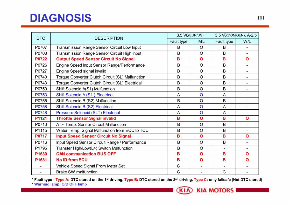
* Fault type - Type A: DTC stored on the 1st driving, Type B: DTC stored on the 2nd driving, Type C: only failsafe (Not DTC stored)* Warning lamp: O/D OFF lamp
Fault type MIL Fault type W/LP0707 Transmission Range Sensor Circuit Low Input B O B -P0708 Transmission Range Sensor Circuit High Input B O B -P0722 Output Speed Sensor Circuit No Signal B O B OP0726 Engine Speed Input Sensor Range/Performance B O B -P0727 Engine Speed signal invalid B O B -P0740 Torque Converter Clutch Circuit (SL) Malfunction B O B -P0743 Torque Converter Clutch Circuit (SL) Electrical B O B -P0750 Shift Solenoid A(S1) Malfunction B O B -P0753 Shift Solenoid A (S1 ) Electrical A O A -P0755 Shift Solenoid B (S2) Malfunction B O B -P0758 Shift Solenoid B (S2) Electrical A O A -P0748 Pressure Solenoid (SLT) Electrical A O A -P1121 Throttle Sensor Signal invalid B O B OP0710 ATF Temp. Sensor Circuit Malfunction B O B -P1115 Water Temp. Signal Malfunction from ECU to TCU B O B -P0717 Input Speed Sensor Circuit No Signal B O B OP0716 Input Speed Sensor Circuit Range / Performance B O B -P1795 Transfer High/Low(L4) Switch Malfunction B O - -P1630 CAN communication BUS OFF B O B OP1631 No ID from ECU B O B O
- Vehicle Speed Signal From Meter Set C - - -- Brake SW malfunction C - C -
3.5 V6(EUR/US) 3.5 V6(DOM/GEN), A-2.5DTC DESCRIPTION

102
P0753P0758P0743
Solenoid No.1 (S1) Open, Ground shortSolenoid No.2 (S2) Open, Ground shortL-up solenoid (SL) Open, Ground short
Troubleshooting
DTC detected condition Cause of failure
Ground short: A failure will be displayed in case any trouble is detected at any other gears 8 times after a trouble is detected at one gear for 0.3 sec..
Open: A failure will be displayed in case any trouble is detected at any other gears 8 times after a trouble is detected at one gear for 0.5 sec..
1. Harness or connector betweeneach shift solenoid and TCM
2. Each shift solenoid
3. TCM
DIAGNOSIS
103
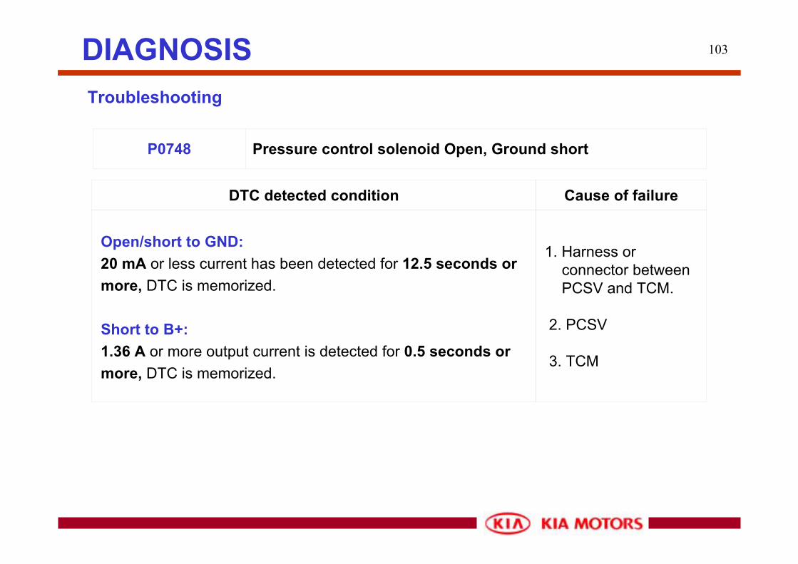
P0748 Pressure control solenoid Open, Ground short
Troubleshooting
DTC detected condition Cause of failure
Open/short to GND: 20 mA or less current has been detected for 12.5 seconds or more, DTC is memorized.
Short to B+: 1.36 A or more output current is detected for 0.5 seconds or more, DTC is memorized.
1. Harness or connector between PCSV and TCM.
2. PCSV
3. TCM
DIAGNOSIS

104
P0716, P0717 P0722
Input speed sensor No signalOutput speed sensor No signal
Troubleshooting
DTC detected condition Cause of failure
No C0 signal: No pulse from C0 is detected while 12 pulses of SP signal detected, failure is 1 time. More than 1000 times continuously detected, it is judged a temporary failure. When it is detected again after IG OFF to ON, total failure become 2 times. DTC is displayed.
No SP signal :No pulses from SP is detected while 45 pulses of C0 signal detected, failure is 1 time. More than 500 times continuously detected, a temporary failure is memorized. When it is detected again after IG OFF to ON, total failure become 2 times. DTC is displayed.
1. Harness or connector betweeneach speed sensorand TCM.
2. Each speed sensor
3. TCM
DIAGNOSIS

105
P0707 TR switch No signal, Open
Troubleshooting
DTC detected condition Cause of failure
No signal:DTC decides a temporary failure in case no signal is transmitted more than 30 seconds. at 1130 rpm. When any trouble is detected again after IG OFF to ON, the number of problems total 2 and DTC decides a failure.
Open:DTC decides a temporary failure in case detected 2 or more signals for more than 10 sec. When any trouble is detectedagain after IG OFF to ON, the number of problems total 2 and DTC decides a failure.
1. Harness or connector betweenTR switch and TCM.
2. TR switch
3. TCM
DIAGNOSIS

106
P0710 ATF temp. sensor open or short to Ground
Troubleshooting
DTC detected condition Cause of failure
Open: When detected detection condition that the abnormal condition of oil temperature after 15 minutes has passed since IG ON, a temporary failure is decided. When it is detected again after IGOFF => ON, the total of failures become 2 times and DTC is decided.
Ground short: When detected detection condition that the abnormal condition for 5 minutes since IG ON, a temporary failure is decided.When it is detected again after IG is OFF => ON, the total of failures become 2 times and DTC is decided.
1. Harness or connector betweenATF temp. sensor and TCM.
2. ATF temp. sensor
3. TCM
DIAGNOSIS

107
TYPE LevelSCSV 1 DRIVING Vbatt - 0V SCSV1:
(1st, 2nd speed operation) (P,N/1st/2nd3rd/4th speed) Io : 1.9A MAX Shift Control Solenoid
Valve no.1SCSV 2 DRIVING Vbatt - 0V SCSV2:
(2nd,3rd speed operation) (P,N/1st/2nd3rd/4th speed) Io : 1.9A MAX Shift Control Solenoid
Valve no.2SNOW SW SW OFF Frequency V GND -0.3 - 2V(2WD VEHICLE) SW ON DC V(IG.1)
V Hi - V Low
16 Pulse/Co cylinder rev.V Hi - V Low <- Output speed12Pulse/TM rev.
OFF SW OFF DC V(IG.1)OFF SW ON DC V GND -0.3 - 2VP DC VbattR/N/D/2/L DC BELOW 0.8VR DC VbattP/N/D/2/L DC BELOW 0.8VIGN OFF DC VbattIGN ON DC Vbatt
2 LOCK-UP SOLENOID DRIVING(over 45km/h) Frequency Vbatt - 0V
Lo : 1.9A MAX<- Torque convetersolenoid valve
3 PCSV IDLE Current controlLo : 1A MAX
Pressure controlsolenoid valve
12 INHIBITOR SW(R)
34 BATT
31 O/D OFF SW
48 INHIBITOR SW(P)
8 VEHICLE SPEED SENSOR DRIVING Pulse
9
7 IDLE PusleC0 CYLINDER REV. SNSR(Over drive clutch drum) <- Input speed sensor
13 Frequency
14 Frequency
REMARKINPUT&OUTPUT SIGNAL
No PIN NAME CONDITION
TCM input and output terminal voltage table
DIAGNOSIS

108
TYPE Level5 EARTH FOR PCSV
S/W OFF DC V(IG.1)S/W ON DC V GND -0.3 - 1.0VIGN OFF DC 0VIDLE DC 0 - 5V
24 EARTH FOR C0 CYLINDERREV. SNSR
26 EARTH FOR VSSL4 SW SW OFF DC V(IG.1)(4WD VEHICLE) SW ON DC V GND -0.3 - 1.0VSNOW LAMP LAMP OFF DC Vbatt(2WD VEHICLE) LAMP ON DC 1.5V MAX
LAMP OFF DC VbattLAMP ON DC 1.5V MAXN DC VbattP/R/D/2/L DC BELOW 0.8VD DC VbattP/R/N/2/L DC BELOW 0.8VIGN OFF DC 0VIGN ON DC 9V - 16V
6 EARTH FOR POWERSW OFF DC V GND -0.3 - 2VSW ON DC Vbatt-2.0 - Vbatt
35 EARTH FOR POWER17 EARTH FOR OTS OTS:Oil Temp. Sensor
REMARKINPUT&OUTPUT SIGNAL
No PIN NAME CONDITION
47 DTC CLEAR SW
18 OIL TEMP SNSR
42
10
29 O/D OFF LAMP
32 INHIBITOR SW(N)
33 INHIBITOR SW(D)
1 POWER(IGN 1)
46 BRAKE SW
TCM input and output terminal voltage table
DIAGNOSIS

109
TYPE LevelContinuity Logic "0" : Vbatt 20% ↓(10.4Kbps) Logic "1" : Vbatt 80% ↑S/W OFF DC V(IG.1)S/W ON DC V GND -0.3 - 1.0V2 DC VbattP/R/N/D/L DC Below 0.8VL DC VbattP/R/N/D/2 DC Below 0.8V
CRUISE CONTROL ACC OFF V(IG.1)(Σ3.5/S-II 2.4) ACC ON V GND -0.3 - 1.5V
Continuity(500kbit/s)Continuity(500kbit/s)
REMARKINPUT&OUTPUT SIGNAL
No PIN NAME CONDITION
45 K-LINE Pulse
28 DIAG. SW
49 INHIBITOR SW(2)
50 INHIBITOR SW(L)
23
41 CAN(HIGH)
22 CAN(LOW)
TCM input and output terminal voltage table
DIAGNOSIS

110Electrical wiring diagram

111
0.0
10.0
20.0
30.0
40.0
50.0
60.0
70.0
80.0
90.0
100.0
0 10 20 30 40 50 60 70 80 90 100 110 120 130 140 150
Vehicle Speed (Kph)
Thro
ttle
open
ing
(%)
2-1 1-2 3-2 2-3 4-3 3-4
4LOFF 4L ON
SHIFT PATTERNBL A-2.5 SHIFT PATTERN (Normal D range:FGR 4.181)
112
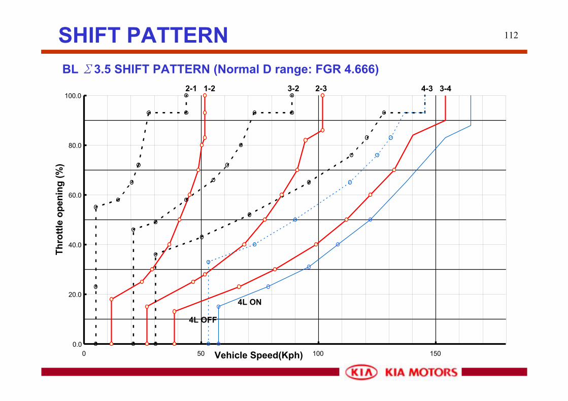
0.0
20.0
40.0
60.0
80.0
100.0
0 50 100 150Vehicle Speed(Kph)
Thro
ttle
open
ing
(%)
2-1 1-2 3-2 2-3 4-3 3-4
4L OFF
4L ON
SHIFT PATTERNBL Σ3.5 SHIFT PATTERN (Normal D range: FGR 4.666)


