
1
FacilitiesChapter 5

2
Objectives
Facility Layouts Process Layout Design Product Layout Design Hybrid Layouts Facility Location
3
Facility Layouts
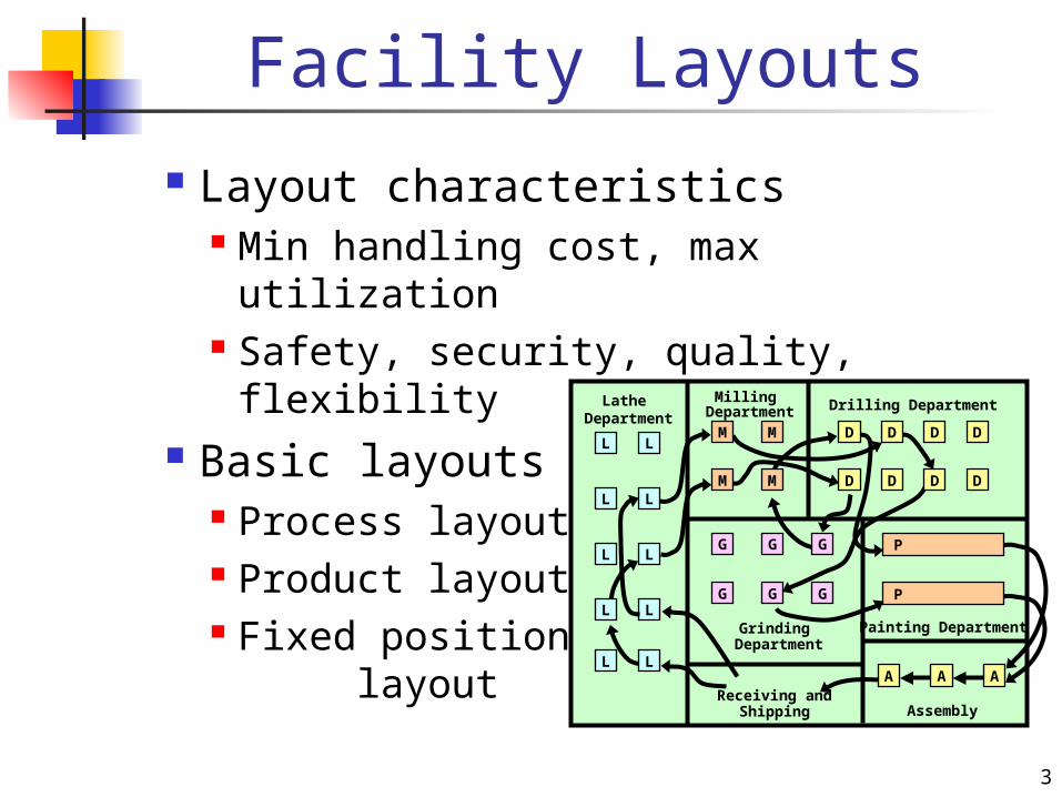
Layout characteristics Min handling cost, max utilization Safety, security, quality, flexibility
Basic layouts Process layout Product layout Fixed position layout
L
L
L
L
L
L
L
L
L
LM
M
M
M
D
D
D
D
D
D
D
D
G
G
G
G
G
G
A A AReceiving and
Shipping Assembly
Painting Department
Lathe Department
Milling Department Drilling Department
Grinding Department
P
P
4
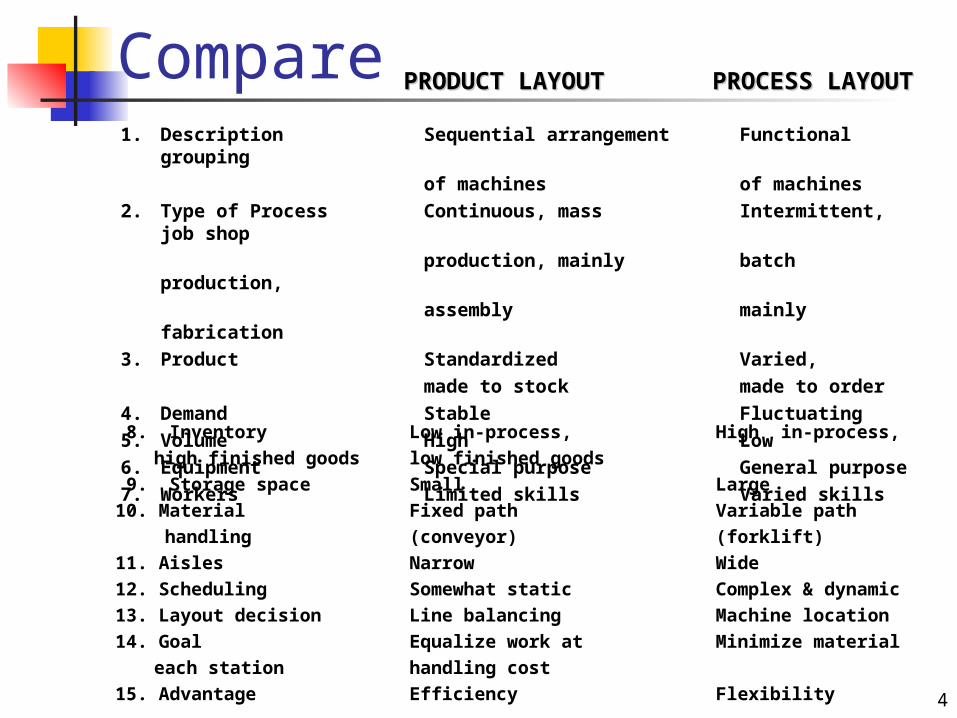
1. Description Sequential arrangement Functional grouping
of machines of machines2. Type of Process Continuous, mass Intermittent,
job shopproduction, mainly batch
production,assembly mainly
fabrication3. Product Standardized Varied,
made to stock made to order4. Demand Stable Fluctuating5. Volume High Low6. Equipment Special purpose General purpose7. Workers Limited skills Varied skills
PRODUCT LAYOUTPRODUCT LAYOUT PROCESS LAYOUTPROCESS LAYOUT
8. Inventory Low in-process, High in-process,high finished goods low finished goods
9. Storage space Small Large10. Material Fixed path Variable path handling (conveyor) (forklift)11. Aisles Narrow Wide12. Scheduling Somewhat static Complex & dynamic13. Layout decision Line balancing Machine location14. Goal Equalize work at Minimize material each station handling cost15. Advantage Efficiency Flexibility
Compare
5
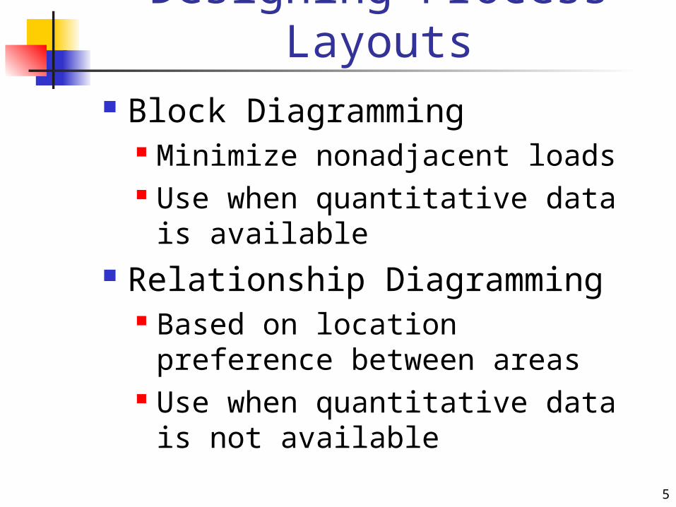
Designing Process Layouts
Block Diagramming Minimize nonadjacent loads Use when quantitative data is
available Relationship Diagramming
Based on location preference between areas
Use when quantitative data is not available
6
Block Diagramming
Create load summary chart
Calculate composite (2 way) movements
Develop trial layouts minimizing number of nonadjacent loads
7
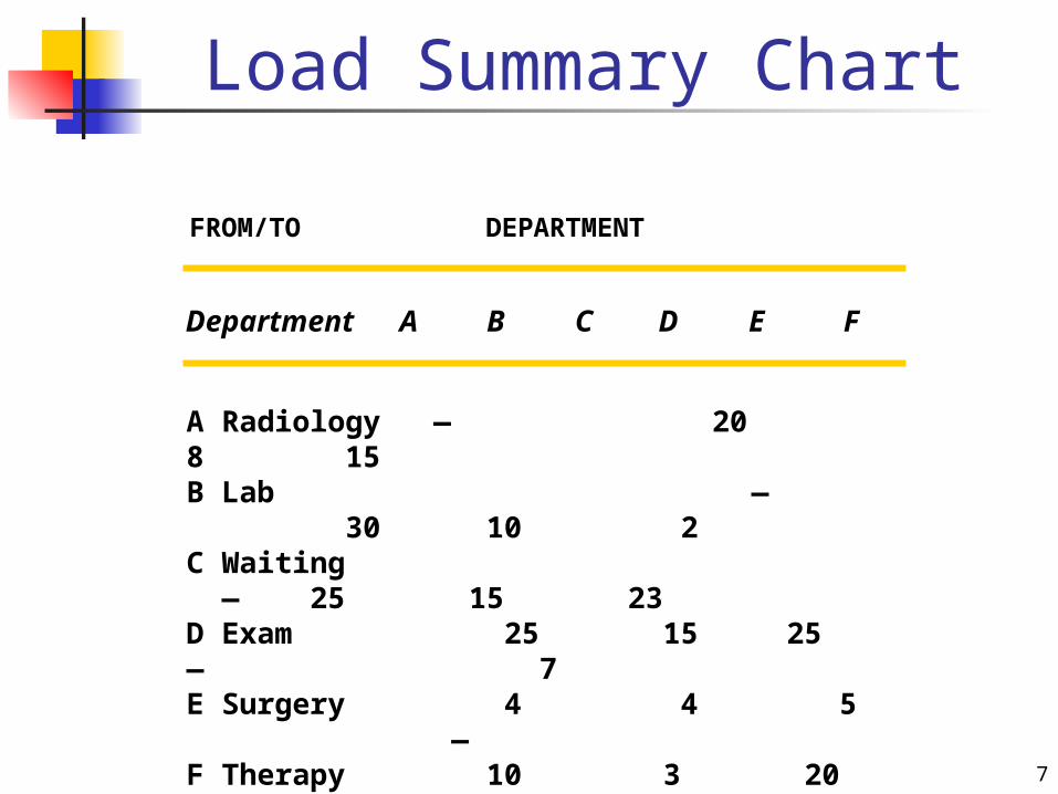
Load Summary Chart
Department A B C D E F
FROM/TO DEPARTMENT
A Radiology — 20 8 15B Lab — 30 10 2C Waiting — 25 15 23D Exam 25 15 25 — 7E Surgery 4 4 5 —F Therapy 10 3 20 5 —

8
Relationship Diagramming
Used when quantitative data is not available
Muther’s grid table displays managers preferences for relative (pair wise) department locations
Denote location preferences with weighted lines in a diagram

9
Muther’s Grid Table
E O
U U
O
OI
I
U
X O
U
AI
O
Radiology
Lab
Waiting
Exam
Surgery
Therapy
A Absolutely necessaryE Especially importantI ImportantO OkayUUnimportantXUndesirable
10
Computerized Layout Solutions
CRAFT – block diagramming
CORELAP – relationship diagramming
Simulation
11
Service Layouts
Tailored to customer needs Max flow and exposure Computer programs
consider Shelf space Demand Profitability
Aesthetically pleasing
12
Designing Product Layouts
Arranged in assembly line Precedence diagram of tasks Jobs divided into work elements Work elements assigned to
workstations Workload balanced along the line
13
Line Balancing Balance the amount of work at
each workstation Achieve a constant throughput
with high efficiency Line balancing process
Precedence diagram Desired cycle time Min number of workstations Group elements into
workstations with acceptable efficiency
14
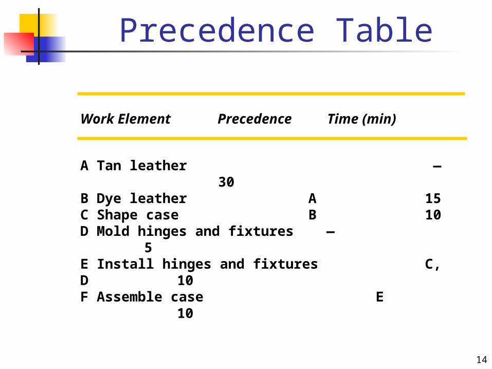
Precedence Table
Work Element Precedence Time (min)
A Tan leather — 30B Dye leather A 15C Shape case B 10D Mold hinges and fixtures —
5E Install hinges and fixtures C, D
10F Assemble case E
10

15
Hybrid Layouts Cellular layouts
Group machines into machining cells
Flexible manufacturing systems Automated machining & material
handling systems Mixed-model assembly lines
Produce variety of models on one line
16
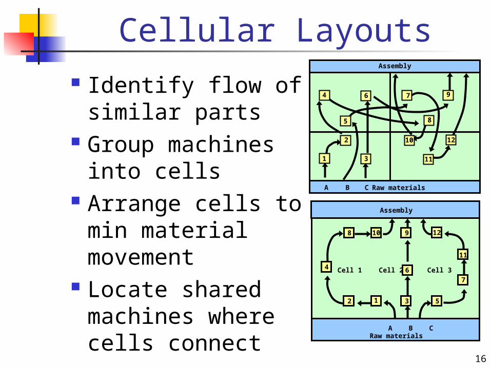
Cellular Layouts Identify flow of
similar parts Group machines
into cells Arrange cells to min
material movement Locate shared
machines where cells connect
CA B Raw materials
Assembly
1
2
3
4
5
6 7
8
9
10
11
12
3
6
9
Assembly
12
4
8 10
5
7
11
12
A B CRaw materials
Cell 1 Cell 2 Cell 3

17
Manufacturing Cell
InOut
Worker 1
Worker 2
Worker 3
Dir
ecti
on
of
par
t m
ove
men
t w
ith
in c
ell
Saw
Lathe
HorizontalMilling
VerticalMilling
Grinder
VerticalMilling
Lathe
Final inspection
Finished part
18
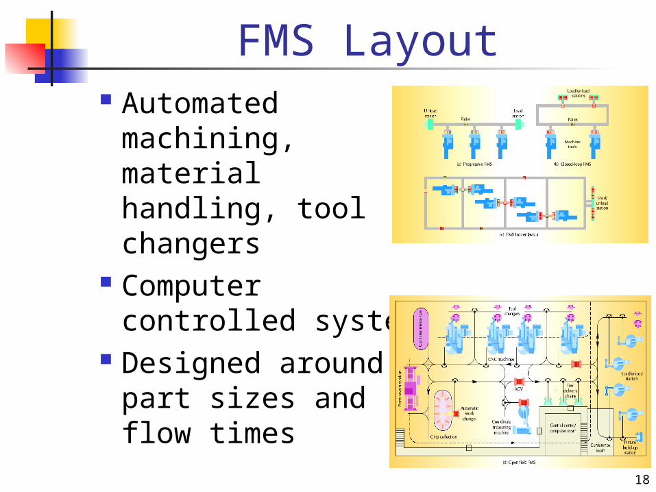
FMS Layout Automated
machining, material handling, tool changers
Computer controlled system
Designed around part sizes and flow times
19
Mixed Model Assembly Lines
Produce multiple models in any order on one assembly line
Issues in mixed model lines Line balancing U-shaped line Flexible workforce Model sequencing
20
Facility Location Types of facilities
Heavy manufacturing Light industry Warehouses and distribution
centers Retail and service
Location factors Standard factors Global, regional, site factors Location incentives
21
Location Analysis
Location factor rating
Center-of-gravity technique
Long-distance technique


