1
Research and Development for the International Linear Collider
presented by Marc Ross - for the ILC Project Managers:
Marc Ross - (Fermilab),
Nick Walker - (DESY),
Akira Yamamoto – (KEK)

Presentation for CSIC-CIEMAT 20 January 2009
Marc Ross, Fermilab 2
ILC – Background:
• traced back to:• e+/e- collider labs –
– where the linear collider was born:– BINP, SLAC, KEK, Cornell, DESY, …
• where cold SRF linac technology started
• Technology Reviewed (TRC); • Recommendation made (ITRP):
– 1995, 2002 and 2004– 0.5-1 TeV ILC: Superconducting Linacs
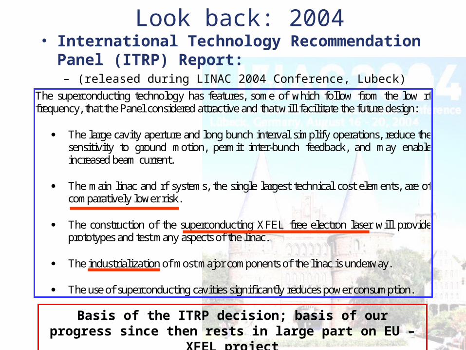
Look back: 2004 • International Technology Recommendation Panel
(ITRP) Report:– (released during LINAC 2004 Conference, Lubeck)
The superconducting technology has features, some of which follow from the low rf frequency, that the Panel considered attractive and that will facilitate the future design:
The large cavity aperture and long bunch interval simplify operations, reduce the sensitivity to ground motion, permit inter-bunch feedback, and may enable increased beam current.
The main linac and rf systems, the single largest technical cost elements, are of
comparatively lower risk.
The construction of the superconducting XFEL free electron laser will provide prototypes and test many aspects of the linac.
The industrialization of most major components of the linac is underway.
The use of superconducting cavities significantly reduces power consumption.
Basis of the ITRP decision; basis of our progress since then rests in large part on EU – XFEL project
Presentation for CSIC-CIEMAT 20 January 2009
Marc Ross, Fermilab 4
International Linear Collider R & D
OUTLINE:
• Reference Design – a global effort• Critical R & D for Accelerator systems
(non SRF)• Critical R & D for Main Linac Technology• Project Preparation• Conclusion

Presentation for CSIC-CIEMAT 20 January 2009
Marc Ross, Fermilab 5
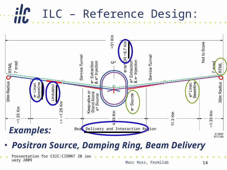
ILC – Reference Design:
• six subsystems
Beam Delivery and Interaction Region
• ~3000 bunches; ~ each 3 nC e+ / e-; ~20 MW avg.
Presentation for CSIC-CIEMAT 20 January 2009
Marc Ross, Fermilab 6
ILC R & D – Global effort
• ILC Reference Design (RD)– based on R & D in support of: TESLA, SBLC, JLC/NLC,
VLEPP, CLIC
• RD Report authored by 325 institutions (including physics/detectors)
• EU-XFEL a large scale demonstration

Presentation for CSIC-CIEMAT 20 January 2009
Marc Ross, Fermilab 7
SRF Test Facilities
7
KEK, Japan
DESY
FNAL
TTF/FLASH~1 GeVILC-like beamILC RF unit(* lower gradient)
NML facilityUnder constructionfirst beam 2010ILC RF unit test
STF (phase I & II)Under constructionfirst beam 2011ILC RF unit test
Presentation for CSIC-CIEMAT 20 January 2009
Marc Ross, Fermilab 8
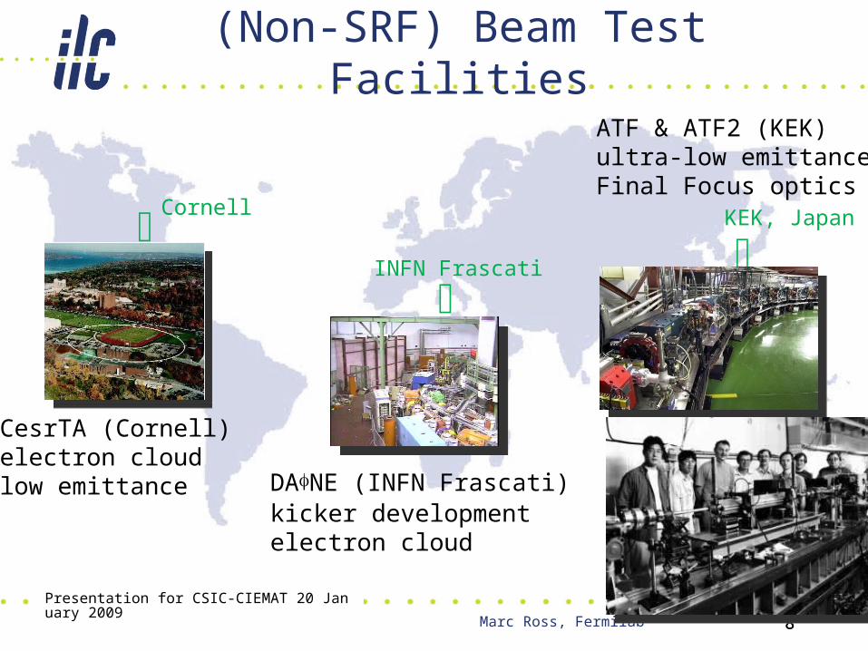
(Non-SRF) Beam Test Facilities
8
KEK, Japan
Cornell
INFN Frascati
CesrTA (Cornell)electron cloudlow emittance DANE (INFN Frascati)
kicker developmentelectron cloud
ATF & ATF2 (KEK)ultra-low emittanceFinal Focus optics

Presentation for CSIC-CIEMAT 20 January 2009
Marc Ross, Fermilab 9
GDE ILC Timeline and Mission
Reference Design Report (RDR)GDE process
TDP 2
LHC physics
2005 2006 2007 2008 20122009 2010 2011 2013
Ready for Project Submission
Tech. Design Phase (TDP) 1
9
Prepare a design and a plan that is completely ready to go - 2012.The request from the HEP community is clear (Brian Foster).Since the timeline is uncertain: focus on R & D for cost and risk reduction develop ties within the accelerator community to facilitate a global project
Presentation for CSIC-CIEMAT 20 January 2009
Marc Ross, Fermilab 10
Resources:Basis: institutional and regional support for science ILC will
provide.Also: Support for science complements strong interest in
emerging technologies
ILC development effort utilizes:1. ILC project preparation-specific funding
• support for design and cost/risk reduction studies for the TDR
2. other project-specific funding (XFEL etc)3. generic R&D
• support for the development of specific technologies
4. combinations of the above• beam test facility support
Presentation for CSIC-CIEMAT 20 January 2009
Marc Ross, Fermilab 11
‘In-Kind’ R&D
• provides return for regions/institutions investing resources for technical development
• To ILC:– Beam Studies– Infrastructure usage– Engineering and Testing
• To contributing Institute / Region:– Technology transfer between partner ILC institutions– Infrastructure development and qualification– Community connection mechanisms
Presentation for CSIC-CIEMAT 20 January 2009
Marc Ross, Fermilab 12
The role of R&D: • in support of a mature, low risk design• take advantage the ongoing, increasing global investment in SRF
and related technology– the big impact of the ITRP decision– Improve performance, reduce cost, challenge limitations, develop inter-regional ties,
develop regional technical centers• Both a ‘project-based’ and a ‘generic’ focus
The ILC has:• A Baseline Design; to be extended and used for comparison (RDR)
– But ready for deployment• Research and Development activities on Alternates to the Baseline
– Engages the community venue for cost-saving / risk-reduction actvities• Plug – compatibility / modularity policy flexibility between the
above– The critical role of associated projects – XFEL, Project X, SNS, JLab12, ERLs, …
• Models of ‘project implementation’– The transition from R&D to a real project– The link between Technical Phase R&D and the project political process
Presentation for CSIC-CIEMAT 20 January 2009
Marc Ross, Fermilab 13
International Linear Collider R & D
• Reference Design – a global effort• Critical R & D for Accelerator systems
(non SRF)• Critical R & D for Main Linac Technology• Project Preparation• Conclusion
Presentation for CSIC-CIEMAT 20 January 2009
Marc Ross, Fermilab 14
ILC – Reference Design:
• Positron Source, Damping Ring, Beam Delivery
Beam Delivery and Interaction RegionExamples:
Presentation for CSIC-CIEMAT 20 January 2009
Marc Ross, Fermilab 15
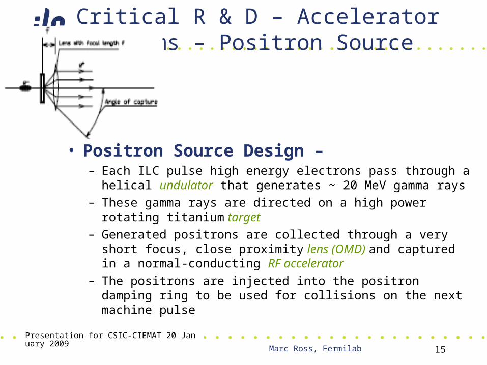
Critical R & D – Accelerator Systems – Positron Source
• Positron Source Design –– Each ILC pulse high energy electrons pass through a helical
undulator that generates ~ 20 MeV gamma rays– These gamma rays are directed on a high power rotating
titanium target– Generated positrons are collected through a very short
focus, close proximity lens (OMD) and captured in a normal-conducting RF accelerator
– The positrons are injected into the positron damping ring to be used for collisions on the next machine pulse

RDR Positron Source Layout
R & D Priorities – Undulator (UK – RAL, Cornell – Mikailichenko) Target (KEK, BINP – Logachev) Optical Matching Device (OMD)- replacement for
‘Flux Concentrator’ Liquid Lithium Lens (KEK, BINP – Logachev)
Capture RF – normal conducting accelerator (Paramonov –INR, SLAC)
Presentation for CSIC-CIEMAT 20 January 2009
Marc Ross, Fermilab 17
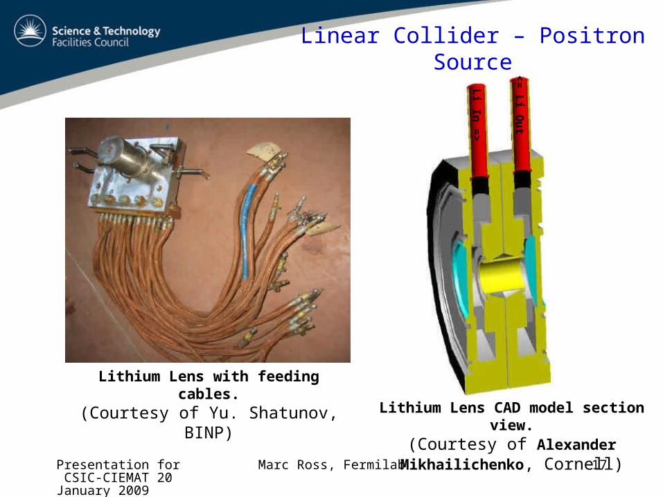
Lithium Lens with feeding cables.(Courtesy of Yu. Shatunov, BINP)
Lithium Lens CAD model section view.(Courtesy of Alexander Mikhailichenko,
Cornell)
Li In
=>
<=
Li O
ut
Linear Collider – Positron Source

Presentation for CSIC-CIEMAT 20 January 2009
Marc Ross, Fermilab 18
BINP – Positron System R & D
• Liquid Lead target development for KEK-B– (years of operational experience at BINP)
– Initial activity for SLAC - NLC
– Alternate to baseline rotating target (also tested at BINP)
– To be installed at KEK-B Linac 2009
• Boron Nitride window / brazing tests underway – Used in liquid target
– Also applicable to Lithium Lens applications
• Liquid Lithium Lens – ~ factor 2 improved capture compared to pulsed electromagnet
– design study in 2009 – support from BINP and KEK
– High pressure Li is main issue
Presentation for CSIC-CIEMAT 20 January 2009
Marc Ross, Fermilab 19
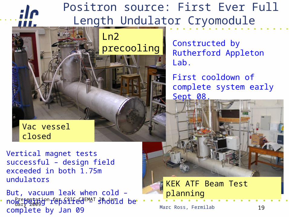
Positron source: First Ever Full Length Undulator Cryomodule
Vac vessel closed
Ln2 precooling
KEK ATF Beam Test planning
Vertical magnet tests successful – design field exceeded in both 1.75m undulators
But, vacuum leak when cold – now being repaired – should be complete by Jan 09
Constructed by Rutherford Appleton Lab.
First cooldown of complete system early Sept 08.

Presentation for CSIC-CIEMAT 20 January 2009
Marc Ross, Fermilab 20
Critical R & D – Accelerator Systems – Damping Ring
• Damping Ring Design– Two 6 km circumference 5GeV damping rings (e+ / e-) – Each pulse inject ~ 3000 bunches and ‘damp’ to very low
emittance in 200 ms– Bunch spacing 6 ns– Extract one – by – one with very fast pulse magnet kicker a
bunch every 300 ns
• Component testing with beam at test facilities:– Cornell (CESR TA)– Dafne (Frascati)– ATF (KEK)

Presentation for CSIC-CIEMAT 20 January 2009
Marc Ross, Fermilab 21
Damping Rings Critical R&D
• Electron cloud.– Goal is to demonstrate effective mitigation methods.– Studies are in progress at CesrTA, DANE, KEKB.
• Fast injection/extraction kickers.– Goal is to demonstrate fast, high-power pulsers meeting ILC
damping rings specifications.– Studies are in progress at ATF, DANE, SLAC.
• Low-emittance tuning.– Goal is to demonstrate reliable operation with 2 pm vertical
emittance. • Typical beam size ~ few microns
– Swiss Light Source has recently achieved 3 pm.– Studies are in progress at ATF and CesrTA.
21

Presentation for CSIC-CIEMAT 20 January 2009
Marc Ross, Fermilab 22
Electron Cloud Studies in CesrTA
Installation of wigglers in former location of CLEO (above).
Retarding field analyzers in wiggler vacuum chambers, and first data (right).
22
Presentation for CSIC-CIEMAT 20 January 2009
Marc Ross, Fermilab 23
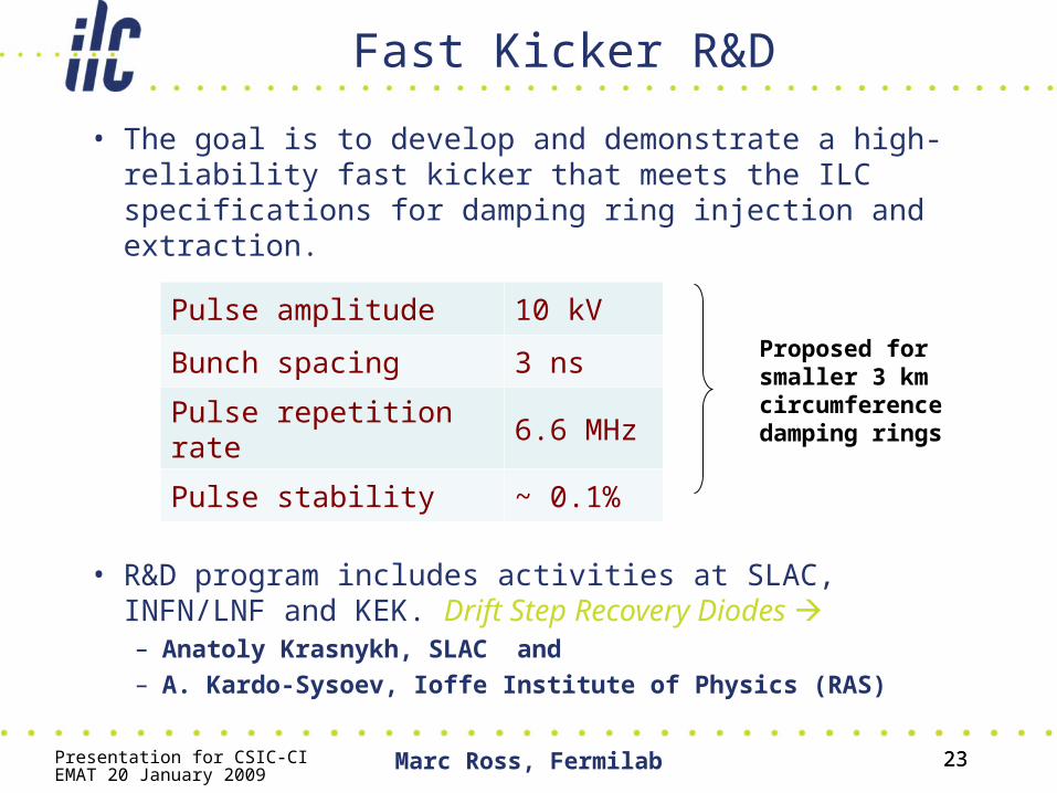
Fast Kicker R&D
• The goal is to develop and demonstrate a high-reliability fast kicker that meets the ILC specifications for damping ring injection and extraction.
• R&D program includes activities at SLAC, INFN/LNF and KEK. Drift Step Recovery Diodes – Anatoly Krasnykh, SLAC and – A. Kardo-Sysoev, Ioffe Institute of Physics (RAS)
23
Pulse amplitude 10 kV
Bunch spacing 3 ns
Pulse repetition rate 6.6 MHz
Pulse stability ~ 0.1%
Proposed for smaller 3 km circumference damping rings

Presentation for CSIC-CIEMAT 20 January 2009
Marc Ross, Fermilab 24
Fast Injection/Extraction Kickers: SLAC
• Researchers at SLAC are investigating two possible technologies: MOSFET array, and DSRD fast switch.
• Both technologies provide attractive characteristics.
• A hybrid pulser may be the best solution.
24
1 ns / division

Presentation for CSIC-CIEMAT 20 January 2009
Marc Ross, Fermilab 25
Critical R & D – Accelerator Systems – Beam Delivery
• Beam Delivery (BDS) Design –– BDS delivers the beam from the high power linac to the
users detector– The BDS provides high power collimation and precision
focusing of the beams – There will be two detectors arranged to they can be
‘exchanged’ using a ‘push-pull’ mechanism– Critical BDS components ‘live’ within the detector
• BDS relies on precision instrumentation systems and optics correction algorithms– Collimation of high density, high power beams is a key
technology– Beam testing is required: ATF2 at KEK

Presentation for CSIC-CIEMAT 20 January 2009
Marc Ross, Fermilab 26
Beam Delivery System R & D• ATF2
– constructed, hardware mostly commissioned
– Next: beam commissioning– Developing long-terms plans for AFT2
• SC FD • squeezed beta* tests, etc
• IR integration (MDI)– have a new version of “IR Interface
Document”– the document is focused on functional
requirements– MDI and DDI (Detector-Detector
Interface)– Also a lot of progress on detailed
Detector and MDI design
26
Andrei Seryi, SLAC, BDS Group Leader
Presentation for CSIC-CIEMAT 20 January 2009
Marc Ross, Fermilab 27
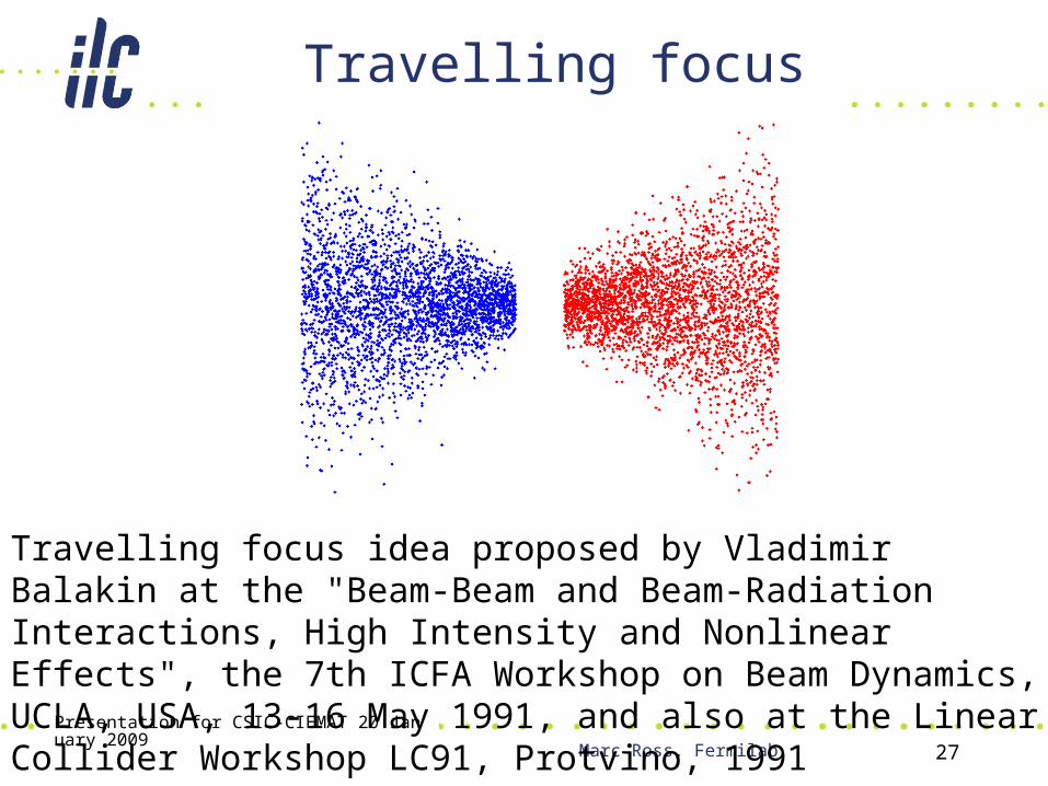
Travelling focus
Travelling focus idea proposed by Vladimir Balakin at the "Beam-Beam and Beam-Radiation Interactions, High Intensity and Nonlinear Effects", the 7th ICFA Workshop on Beam Dynamics, UCLA, USA, 13-16 May 1991, and also at the Linear Collider Workshop LC91, Protvino, 1991
Presentation for CSIC-CIEMAT 20 January 2009
Marc Ross, Fermilab 28
International Linear Collider R & D
• Reference Design – a global effort• Critical R & D for Accelerator systems
(non SRF)• Critical R & D for Main Linac Technology• Project Preparation• Conclusion
Presentation for CSIC-CIEMAT 20 January 2009
Marc Ross, Fermilab 29
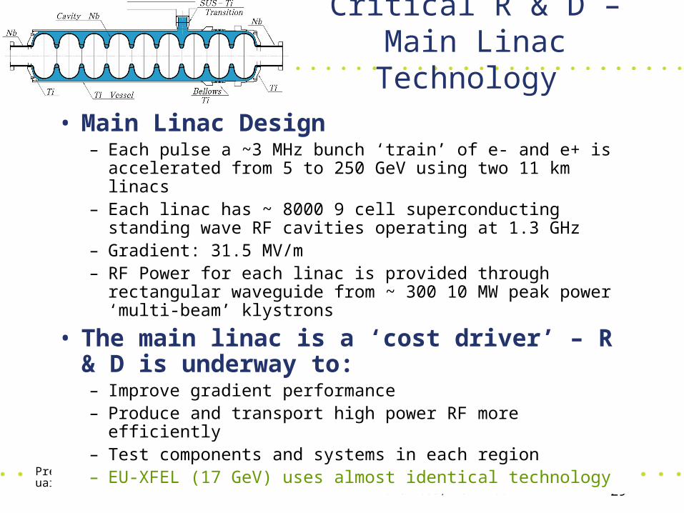
Critical R & D – Main Linac Technology
• Main Linac Design– Each pulse a ~3 MHz bunch ‘train’ of e- and e+ is
accelerated from 5 to 250 GeV using two 11 km linacs– Each linac has ~ 8000 9 cell superconducting standing wave
RF cavities operating at 1.3 GHz– Gradient: 31.5 MV/m– RF Power for each linac is provided through rectangular
waveguide from ~ 300 10 MW peak power ‘multi-beam’ klystrons
• The main linac is a ‘cost driver’ – R & D is underway to:– Improve gradient performance– Produce and transport high power RF more efficiently– Test components and systems in each region– EU-XFEL (17 GeV) uses almost identical technology

Presentation for CSIC-CIEMAT 20 January 2009081209
Marc Ross, FermilabILC Global Design Effort
3030
Superconducting Cavity R&D
Niobium Sheet metal cavity Fabrication:
Forming and welding (EBW)
Surface Process: Chemical etching and polishing Cleaning
Inspection/Tests: Optical Inspection (warm) Thermometry (cold)
Presentation for CSIC-CIEMAT 20 January 2009
Marc Ross, Fermilab 31
One Vendor Yield(A6, A7, A8, A11, A12, A15, AC115, AC117, AC122, 125, 126)
0
0.2
0.4
0.6
0.8
1
1.2
>15 >20 >25 >30 >35 >40
Gradient (MV/m)
Fra
cti
on
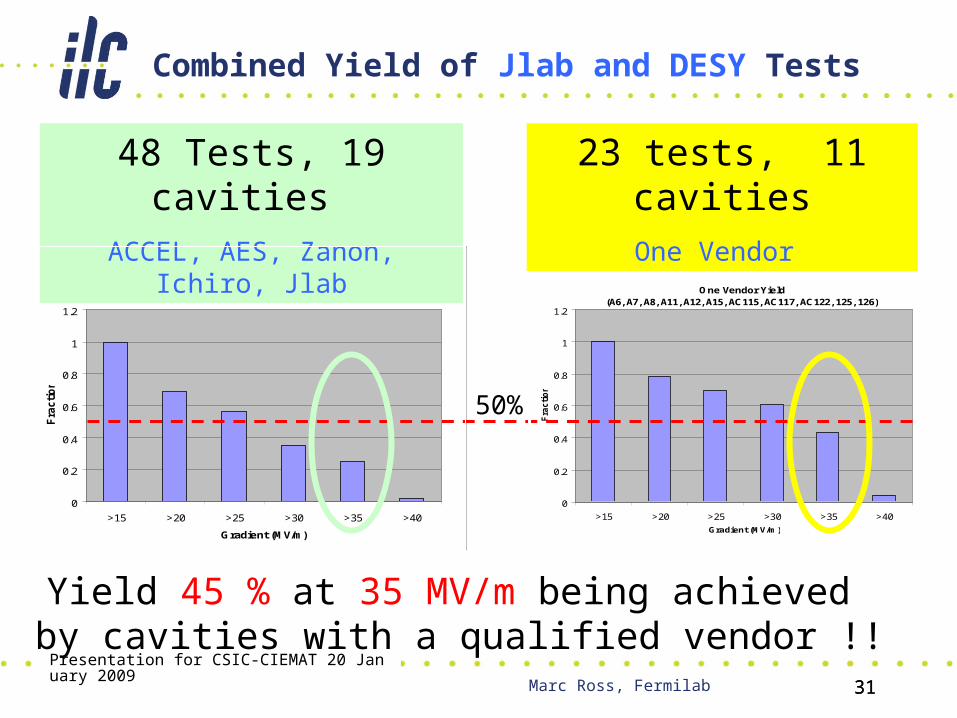
Combined Yield of Jlab and DESY Tests
23 tests, 11 cavitiesOne Vendor
All Vendor Yield(A6, A7, A8, A11, A12, A15, AES 1- 4, Ichiro5, J2,AC115, AC117, AC122,
125, 126, Z139, 143)
0
0.2
0.4
0.6
0.8
1
1.2
>15 >20 >25 >30 >35 >40
Gradient (MV/m)
Fra
cti
on
48 Tests, 19 cavities ACCEL, AES, Zanon, Ichiro, Jlab
50%
Yield 45 % at 35 MV/m being achieved by cavities with a qualified vendor !!
31

Presentation for CSIC-CIEMAT 20 January 2009
Marc Ross, Fermilab 32
• Russian Design team; fabricated in Japan
• Most successful 10 MW multi-beam klystron BASELINE
Klystron RF Power Source
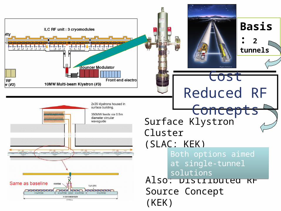
Also: Distributed RF Source Concept(KEK)
Surface Klystron Cluster(SLAC; KEK)
Both options aimed at single-tunnel solutionsBoth options aimed at single-tunnel solutions
Basis: 2 tunnels
Cost Reduced RF Concepts
Presentation for CSIC-CIEMAT 20 January 2009
Marc Ross, Fermilab 34
Civil Engineering
• 30% of the estimated cost• Three sample sites studied – Japan, CERN,
Illinois– Quite similar configurations; deep rock dual tunnel
• JINR suggested a 4th sample site near Dubna– Studied ~ 20 years ago
• This site has several contrasting features that provide a comparison basis– Single tunnel with near surface building
– Soft tunneling material
• Siting process is political – but it is useful to have studied and reported sample sites
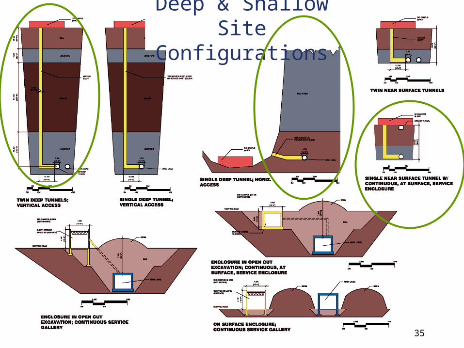
Deep & Shallow Site Configurations
35
Presentation for CSIC-CIEMAT 20 January 2009
Marc Ross, Fermilab 36
International Linear Collider R & D
• Reference Design – a global effort• Critical R & D for Accelerator systems
(non SRF)• Critical R & D for Main Linac Technology• Project Preparation
– Collaboration with CERN– Making the transition from broad-based R & D to a practical
Project
• Conclusion

Presentation for CSIC-CIEMAT 20 January 2009
Marc Ross, Fermilab 37
Collaboration with CLIC / CERN
• Formulated (Barish/Aymar) 11.2007– Established in 02.2008; initially 5 working groups
• ‘Exclusive’ strategy: – pick and choose efforts with strong commonality; optimize use of
resources– startup philosophy: choose tasks more likely to succeed
• Promoting communication / links between the two groups– will facilitate discussion and consensus building between teams– improving the credibility of both
• Common costing methodology / basis is a collaboration priority

Presentation for CSIC-CIEMAT 20 January 2009
Marc Ross, Fermilab 38
ILC R & D Resources
• (summarized in R & D Plan; published 2008.06)• 2007-2010 4 years
Technical Area: Effort (years * people)
Funds (M$)
Superconducting RF Tech
615 90
CFS / Global (Controls) 112 4
Accelerator Systems 415 27
Total 1142 121

Presentation for CSIC-CIEMAT 20 January 2009
Marc Ross, Fermilab 39
International Linear Collider R & D
• Reference Design – a global effort• Critical R & D for Accelerator systems
(non SRF)• Critical R & D for Main Linac Technology• Project Preparation• Conclusion
Presentation for CSIC-CIEMAT 20 January 2009
Marc Ross, Fermilab 40
Conclusion
• ILC Global Design Effort has 3 goals:– Developing the community– Doing R & D– Designing the ILC and preparing a practical Project– Until end 2012
• ILC GDE is launching the first *truly global large scale international science project*– Based roughly equally in each of three regions: Americas,
Europe and Asia
• We invite and strongly encourage your continued and increased participation!


