1 | SHILPI CABLE Note: It is our constant endeavor to improve our products. Thus there may be changes in specifications. The updated one may be taken from local sales representative.

SHILPI CABLE | 2

3 | SHILPI CABLE
Vision & Mission
Vision:"Shilpi's Vision is to be a global organisation providing Energy Storage, Communication & Connectivity, and Electrical solutions, recognised for its technology and innovation. We will strive to be a billion dollar corporation by 2020".
Mission:Shilpi's Mission is to achieve the vision through global reach, customer focus, people centricity, and value creation for all stakeholders.
SHILPI CABLE | 4
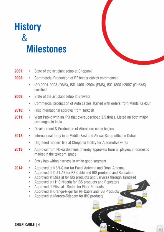
History & Milestones
2007: • StateoftheartplantsetupatChopanki
2008: • CommercialProductionofRFfeedercablescommenced
• ISO9001:2008(QMS),ISO14001:2004(EMS),ISO18001:2007(OHSAS) certified
2009: • StateoftheartplantsetupatBhiwadi
• CommercialproductionofAutocablesstartedwithordersfromMindaKakklur
2010: • FirstinternationalapprovalfromTurkcell
2011: • WentPublicwithanIPOthatoversubscribed3.5times.Listedonbothmajor exchangesinIndia
• Development&ProductionofAluminumcablebegins
2012: • InternationalforayintoMiddleEastandAfrica.SetupofficeinDubai
• UpgradedmodernlineatChopankifacilityforAutomotivewires
2013: • ApprovalfromNokiaSiemens,therebyapprovalsfromallplayersindomestic market in the telecom space
• Entryintowiringharnessinwhitegoodsegment
2014: • ApprovedatNSN-QatarforPanelAntennaandOmniAntenna • ApprovedatDU-UAEforRFCableandIBSproductsandRepeaters • ApprovedatEtisalatforIBSproductsandServicesthroughTamdeed • ApprovedatIHSNigeriaforIBSproductsandRepeaters • ApprovedatEtisalat–SudanforFiberProducts • ApprovedatOrange-NigerforRFCableandIBSProducts • ApprovedatMoroco-TelecomforIBSproducts

5 | SHILPI CABLE
Manish Bhatt (CEO)Manishisamanagementprofessionalwith24yearsof industrialexperience.HeisB.TechfromIITMumbaiandMBAfromIIMLucknow.Hehasledvarioustransformationprojectssuccessfullyinvariouscompanies,liketheDirectSalestoIndirectSales,OutsourcingofCustomerServicestoFranchisee,“Wholesale”to“Distributor-Retail”salesandmade“Product-MarketMix”changesforhigherprofitability.Hehasalsoplannedandimple-mentedmanyGreenFieldProjectsinIndia.
Sunil Kumar Singh (Operation Head)Sunil isMBAOperationswith17years richTechno-commercial experience inProjectPlanning&Execution,Manufacturing,PPC,BusinessDevelopment,OperationsManagementincompanieslikeGlosterCable,PolycabIndustries,RRKabel,KEIIndustries&JainsonCables.
Akhil Srivastava (Business Head-Harness)AkhilisaMechanicalEngineer,MBAwith18+yearsofexperienceinWireHarnessbusiness.HisrichexperienceareasofOperations,Marketing&BusinessDevelopmentincompanieslikeMothersonSumi,PurolatorandAltosetc.
R Madhavan (Business Head-Telecom)Madhavan is aBE (Electrical&Electronics) fromMysoreUniversity.Hehas20plusyearsof experience inTelecomIndustry.HisexperienceincludesassignmentsofKeyAccountManagerwithcompanieslikeIndchemElectronics,Nera(nowpartofCeragonnetworks),AndrewCorporation&VolexInterconnect.
Ashish Kukreja (Business Head-2 Wheeler OEM)Ashish Kukreja is an Engineering Graduate fromPune University. He has over 17 years of rich AutomotiveIndustry experience inSalesSegment,BusinessDevelopment,MarketingandProductManagement.HehashandledmarketingandbusinessdevelopmentrolesinWires&HarnesscompanieslikeSCTL,DTPL&MindaandhasbeenworkingintheAutoCablesbusinessforthelast6years.
Vinay Kant Sharma (Business Head-4 Wheeler OEM)Vinay is aMechanical Engineerwith18yearsof experience inBusinessDevelopment&Marketing.HehasworkedinCompaniesLikeAlphaMaier,MadhusudanAutoLimited,OxeecoTechnologiesetc.HehasdevelopednewbusinesseswithkeyaccountslikeMaruti,VW,GM,Mahindra,TataMotors,Ford,Fiat,HMSI,Piaggio.
Amarpreet Baidwan (Head-HR)AmarpreetisaHRprofessionalwith17yrsofworkexperience.HeisMBA-HRfromPuneUniversity,DLL&LWfromSymbiosisPune,Diplomain-Training&DevelopmentfromI.S.T.D,DelhiandDiplomainStatisticsfromPunjabUniversity,Chandigarh.Hehasworked inTelecom,Retail,AutomotiveOEM,RealEstate,Chemical&ElectricalEngineeringsectors.HehashandledLegal,HR,Admin,Civil&ElectricalWorksrelatedissuesfornewBusinessProjects.
Manoj Arora (CFO)ManojArora(CFO)is(CA)with13yrsofexperienceinFinance&Accountsfunction.Hisexperienceincludesassignments in companies like Protech Biosystems Limited, Geoservices Australasia Pvt Ltd, Australia (USMNC)andAmishAmbani&Company.
Kuldeep Zadoo (Purchase Head)Kuldeep is a BE (Industrial Electronics) fromCollege of EngineeringOsmanabad (Dr.BabaSahebAmbedkarMartha Wada University). He has 12 years of experience in Supply Chain Management, Global & LocalSourcing).Hisexperience includesassignments incompanies likeSidhwalRefrigeration,LGElectronicsLtd,HCLInfosystemsLtd.
Our Team
SHILPI CABLE | 6
Hemant Garg (CFO)CAHemantGargisaQualifiedCharteredAccountant,havingovermorethan9yearsofexperienceinhandlingthe overall finance function with strategic planning, budgeting and statutory compliance, internal controls and processreviewacrossthetenures.GarghasworkedwithreputedorganizationslikeISGECHeavyEngineeringLimited in India as Head of Internal Audit Department, Mammut Construction Group FZCO in Dubai, ExcelIndustryCoLLCinAjmanandAlNasserIndustrialEnterprisesinAbuDhabi.
Vinit Jain (GM-Techno-Commercial)VinitJainisTotalQualityManagement(TQM)professionalwith22yearsofIndustrialconstructionandTelecomSectorGlobalexperience.HeisBEandMBA(TQM)fromSingaporeUniversityandSixSigmaBlackBeltcertified.Hehasmanagedmorethan9000BTSsitesinIndiaandAbroadprojects.ImplementedQMS,SPMandMQMprocessesatGloballevelinMultiNationalTelecomcompaniesandnowheismanagingSalesandMarketingasGM-Techno-CommercialinMiddleEastandAfricamarket.
Shamim Abbass (Manager Trade Finance)Shamimmanages Trade Finance to expand existing vendor engagements offering Import and Export TradeFinance.Heleadsstructuringoftradefinanceopportunitiestomaximizeliquiditywhilemeetingenterpriseriskmanagementrequirements.Heidentifiesproductgaps/newproductopportunitiestoinfluencethedevelopmentand expansion of finance, including creation of alternative structures and geographical expansion.
Malik Moussaoui (Marketing Manager ME & Africa)Malikhasmorethan10yearsofexperienceintelecomindustry.HestartedcareerasaprojectmanagerandhasworkedwithcompanieslikeOrange,MTN,HuaweiandSterliteTechnologiesbeforejoiningShilpiWorldWide.
Madan Kumar (Regional Sales Manager) Madan Kumar is an Electronics and Communication Engineer fromBangalore University, havingworked asTechnicalSalesandMarketingpersonforbothIndianandoverseasMarket inMicroqualTechnoLimitedwith12+YearsofexperienceinTelecomandnowhehasjoinedShilpiWorldWide.
Prashant Jadhav (Product Manager)Prashant is responsible for the management of new or existing products within the organization. With thesubstantial knowledge of business he understands how a product fits into the overall guidance and vision of the company.
7 | SHILPI CABLE Note: It is our constant endeavor to improve our products. Thus there may be changes in specifications. The updated one may be taken from local sales representative.
TableofContents
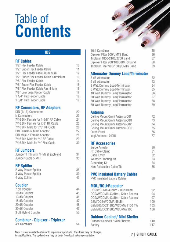
RF Cables1/2”FlexFeederCable 101/2”SuperFlexFeederCable 111/2”FlexFeedercableAluminium 121/2”SuperFlexFeederCableAluminium 137/8”FlexFeederCable 147/8”SuperFlexFeederCable 157/8”FlexFeederCableAluminium 167/8”LowLossFeederCable 1711/4”FlexFeederCable 1815/8”FlexFeederCable 19
RF Connectors, RF AdaptorsDIN(7/16)Connectors 22NConnectors 237/16DINFemalefor1-5/8”RFCable 247/16DINFemalefor7/8”RFCable 257/16DINMalefor7/8”RFCable 26DINFemale-NMaleAdaptor 27DINMale-NFemaleAdaptor 287/16DINMalefor½”SFCable 297/16DINMalefor½”FlexCable 30
RF JumpersJumper1mtrwithN(M)ateachend 34JumperCable5MTR 35
RF Splitter2WayPowerSplitter 383WayPowerSplitter 394WaySplitter 40
Coupler7dBCoupler 4410dBCoupler 4513dBCoupler 4615dBCoupler 4720dBCoupler 4830dBCoupler 493dBHybridCoupler 50
Combiner - Diplexer - Triplexer4:4Combiner 54
16:4Combiner 55DiplexerFilter900/UMTSBand 56Triplexer1800/2100/2700Band 57DiplexerFilter900/1800/UMTSBand 58TriplexerFilter900/1800/UMTSBand 59
Attenuator-Dummy Load/Terminator3dBAttenuator 626dBAttenuator 632WattDummyLoad/Terminator 645WattDummyLoad/Terminator 6510WattDummyLoad/Terminator 6650WattDummyLoad/Terminator 6750WattDummyLoad/Terminator 6850WattDummyLoad/Terminator 69
AntennaCeilingMountOmniAntenna-00F 72CeilingMountOmniAntenna-00R 73CeilingMountOmniAntenna-002 74CeilingMountOmniAntenna-OSR 75PatchPanel 76YagiAntenna10DBI 77
RF AccessoriesSurgeArrestor 80RFCableClamp 81CableEntry 82WeatherProofingKit 83GroundingKit 84Non-ReleasableCableTie 85
PVC Insulated Battery CablesPVCInsulatedBatteryCables 88
MOU/ROU/Repeater DCS/WCDMA43dBm-DuelBand 92DCS&WCDMA43dBm-CableAccess 94DCS&WCDMA43dBm-CableAccess 97 GSM/DCS/WCDMA46dBm 100GSM900/DCS1800/WCDMA21001W 103GSM900/DCS1800/WCDMA2100 106
Outdoor Cabinet/ Mini ShelterOutdoorCabinets/MiniShelters 110Battery 117
IBS

SHILPI CABLE | 8Note: It is our constant endeavor to improve our products. Thus there may be changes
in specifications. The updated one may be taken from local sales representative.SHILPI CABLE | 8

9 | SHILPI CABLE Note: It is our constant endeavor to improve our products. Thus there may be changes in specifications. The updated one may be taken from local sales representative.
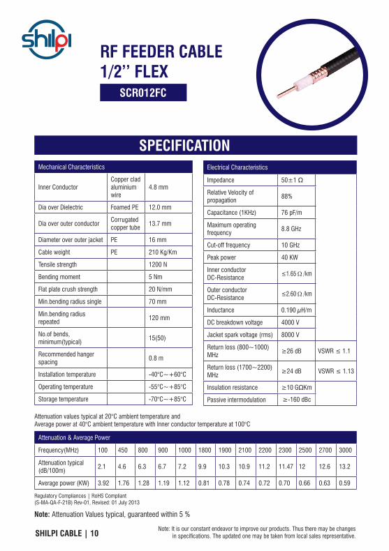
RF CABLESRadioFrequencycableisusedasatransmissionlineforradiofrequencysignals.Itsapplicationsincludefeedlinesconnectingradiotransmittersandreceiverswiththeirantennas.RFcablealsoprovides protection of the signal from external electromagnetic interference.RFCablesareavailablein¼”,½”,7/8”,1-1/4”and1-5/8”sizes.Copper&Aluminiumvariantsareavailable.
9 | SHILPI CABLE
SHILPI CABLE | 10Note: It is our constant endeavor to improve our products. Thus there may be changes
in specifications. The updated one may be taken from local sales representative.
RF FEEDER CABLE1/2’’ FLEX
SCR012FC
RF FEEDER CABLE1/2’’ FLEX
SCR012FC
Electrical Characteristics
Impedance 50±1 Ω
Relative Velocity of propagation
88%
Capacitance (1KHz) 76 pF/m
Maximum operating frequency
8.8 GHz
Cut-off frequency 10 GHz
Peak power 40 KW
Inner conductor DC-Resistance
≤1.65 /km
Outer conductor DC-Resistance
≤2.60 /km
Inductance 0.190 μH/m
DC breakdown voltage 4000 V
Jacket spark voltage (rms) 8000 V
Return loss (800~1000) MHz
≥26 dB VSWR ≤ 1.1
Return loss (1700~2200) MHz
≥24 dB VSWR ≤ 1.13
Insulation resistance ≥10 GΩKm
Passive intermodulation ≥160 dBc
Mechanical Characteristics
Inner ConductorCopper clad aluminium wire
4.8 mm
Dia over Dielectric Foamed PE 12.0 mm
Dia over outer conductorCorrugated copper tube
13.7 mm
Diameter over outer jacket PE 16 mm
Cable weight PE 210 Kg/Km
Tensile strength 1200 N
Bending moment 5 Nm
Flat plate crush strength 20 N/mm
Min.bending radius single 70 mm
Min.bending radius repeated
120 mm
No.of bends, minimum(typical)
15(50)
Recommended hanger spacing
0.8 m
Installation temperature -40°C~+60°C
Operating temperature -55°C~+85°C
Storage temperature -70°C~+85°C
Attenuation & Average Power
Frequency(MHz) 100 450 800 900 1000 1800 1900 2100 2200 2300 2500 2700 3000
Attenuation typical (dB/100m)
2.1 4.6 6.3 6.7 7.2 9.9 10.3 10.9 11.2 11.47 12 12.6 13.2
Average power (KW) 3.92 1.76 1.28 1.19 1.12 0.81 0.78 0.74 0.72 0.70 0.66 0.63 0.59
Note: Attenuation Values typical, guaranteed within 5 %
SPECIFICATION
Attenuation values typical at 20°C ambient temperature andAverage power at 40°C ambient temperature with Inner conductor temperature at 100°C
SHILPI CABLE | 07
Regulatory Compliances | RoHS Compliant(S-MA-QA-F-21B) Rev-01, Revised: 01 July 2013 01 Jan 2007
≥-160dBc
RF FEEDER CABLE1/2’’ SUPER FLEX
SCR012SC
Electrical Characteristics
Impedance 50±1 Ω
Relative Velocity of propagation
81%
Capacitance (1KHz) 80 pF/m
Maximum operating frequency
10.2 GHz
Cut-off frequency 13 GHz
Peak power 19 KW
Inner conductor DC-Resistance
≤2.8 Ω/Km
Outer conductor DC-Resistance
≤3.8 Ω/Km
Inductance 0.200 μH/m
DC breakdown voltage 2500 V
Jacket spark voltage (rms) 5000 V
Return loss (800~1000) MHz
≥26 dB VSWR ≤ 1.1
Return loss (1700~2200) MHz
≥24 dB VSWR ≤ 1.13
Insulation resistance ≥10 GΩKm
Passive intermodulation ≥160 dBc
Mechanical Characteristics
Inner ConductorCopper clad aluminium wire
3.55 mm
Dia over Dielectric Foamed PE 9.0 mm
Dia over outer conductorCorrugated copper tube
12.0 mm
Diameter over outer jacket PE 13.5 mm
Cable weight PE 175 Kg/Km
Tensile strength 1000 N
Bending moment 3 Nm
Flat plate crush strength 15 N/mm
Min.bending radius single 15 mm
Min.bending radius repeated
30 mm
No.of bends, minimum(typical)
20(50)
Recommended hanger spacing
0.8 m
Installation temperature -40°C~+60°C
Operating temperature -55°C~+85°C
Storage temperature -70°C~+85°C
Attenuation & Average Power
Frequency(MHz) 100 450 800 900 1000 1800 1900 2100 2200 2300 2500 2700 3000
Attenuation typical (dB/100m)
3 6.8 9.3 9.9 10.5 14.6 15 15.9 16.3 16.75 17.6 18.4 19.5
Average power (KW) 2.6 1.23 0.91 0.85 0.81 0.58 0.57 0.54 0.53 0.52 0.49 0.47 0.44
Note: Attenuation Values typical, guaranteed within 5 %
SPECIFICATION
Attenuation values typical at 20°C ambient temperature andAverage power at 40°C ambient temperature with Inner conductor temperature at 100°C
Regulatory Compliances | RoHS Compliant(S-MA-QA-F-21E) Rev-01, Revised: 01 July 2013 01 Jan 2007
08 | SHILPI CABLE

11 | SHILPI CABLE Note: It is our constant endeavor to improve our products. Thus there may be changes in specifications. The updated one may be taken from local sales representative.
RF FEEDER CABLE1/2’’ SUPER FLEX
SCR012SC
RF FEEDER CABLE1/2’’ FLEX
SCR012FC
Electrical Characteristics
Impedance 50±1 Ω
Relative Velocity of propagation
88%
Capacitance (1KHz) 76 pF/m
Maximum operating frequency
8.8 GHz
Cut-off frequency 10 GHz
Peak power 40 KW
Inner conductor DC-Resistance
≤1.65 /km
Outer conductor DC-Resistance
≤2.60 /km
Inductance 0.190 μH/m
DC breakdown voltage 4000 V
Jacket spark voltage (rms) 8000 V
Return loss (800~1000) MHz
≥26 dB VSWR ≤ 1.1
Return loss (1700~2200) MHz
≥24 dB VSWR ≤ 1.13
Insulation resistance ≥10 GΩKm
Passive intermodulation ≥160 dBc
Mechanical Characteristics
Inner ConductorCopper clad aluminium wire
4.8 mm
Dia over Dielectric Foamed PE 12.0 mm
Dia over outer conductorCorrugated copper tube
13.7 mm
Diameter over outer jacket PE 16 mm
Cable weight PE 210 Kg/Km
Tensile strength 1200 N
Bending moment 5 Nm
Flat plate crush strength 20 N/mm
Min.bending radius single 70 mm
Min.bending radius repeated
120 mm
No.of bends, minimum(typical)
15(50)
Recommended hanger spacing
0.8 m
Installation temperature -40°C~+60°C
Operating temperature -55°C~+85°C
Storage temperature -70°C~+85°C
Attenuation & Average Power
Frequency(MHz) 100 450 800 900 1000 1800 1900 2100 2200 2300 2500 2700 3000
Attenuation typical (dB/100m)
2.1 4.6 6.3 6.7 7.2 9.9 10.3 10.9 11.2 11.47 12 12.6 13.2
Average power (KW) 3.92 1.76 1.28 1.19 1.12 0.81 0.78 0.74 0.72 0.70 0.66 0.63 0.59
Note: Attenuation Values typical, guaranteed within 5 %
SPECIFICATION
Attenuation values typical at 20°C ambient temperature andAverage power at 40°C ambient temperature with Inner conductor temperature at 100°C
SHILPI CABLE | 07
Regulatory Compliances | RoHS Compliant(S-MA-QA-F-21B) Rev-01, Revised: 01 July 2013 01 Jan 2007
RF FEEDER CABLE1/2’’ SUPER FLEX
SCR012SC
Electrical Characteristics
Impedance 50±1 Ω
Relative Velocity of propagation
81%
Capacitance (1KHz) 80 pF/m
Maximum operating frequency
10.2 GHz
Cut-off frequency 13 GHz
Peak power 19 KW
Inner conductor DC-Resistance
≤2.8 Ω/Km
Outer conductor DC-Resistance
≤3.8 Ω/Km
Inductance 0.200 μH/m
DC breakdown voltage 2500 V
Jacket spark voltage (rms) 5000 V
Return loss (800~1000) MHz
≥26 dB VSWR ≤ 1.1
Return loss (1700~2200) MHz
≥24 dB VSWR ≤ 1.13
Insulation resistance ≥10 GΩKm
Passive intermodulation ≥160 dBc
Mechanical Characteristics
Inner ConductorCopper clad aluminium wire
3.55 mm
Dia over Dielectric Foamed PE 9.0 mm
Dia over outer conductorCorrugated copper tube
12.0 mm
Diameter over outer jacket PE 13.5 mm
Cable weight PE 175 Kg/Km
Tensile strength 1000 N
Bending moment 3 Nm
Flat plate crush strength 15 N/mm
Min.bending radius single 15 mm
Min.bending radius repeated
30 mm
No.of bends, minimum(typical)
20(50)
Recommended hanger spacing
0.8 m
Installation temperature -40°C~+60°C
Operating temperature -55°C~+85°C
Storage temperature -70°C~+85°C
Attenuation & Average Power
Frequency(MHz) 100 450 800 900 1000 1800 1900 2100 2200 2300 2500 2700 3000
Attenuation typical (dB/100m)
3 6.8 9.3 9.9 10.5 14.6 15 15.9 16.3 16.75 17.6 18.4 19.5
Average power (KW) 2.6 1.23 0.91 0.85 0.81 0.58 0.57 0.54 0.53 0.52 0.49 0.47 0.44
Note: Attenuation Values typical, guaranteed within 5 %
SPECIFICATION
Attenuation values typical at 20°C ambient temperature andAverage power at 40°C ambient temperature with Inner conductor temperature at 100°C
Regulatory Compliances | RoHS Compliant(S-MA-QA-F-21E) Rev-01, Revised: 01 July 2013 01 Jan 2007
08 | SHILPI CABLE
≥-160dBc
SHILPI CABLE | 12Note: It is our constant endeavor to improve our products. Thus there may be changes
in specifications. The updated one may be taken from local sales representative.
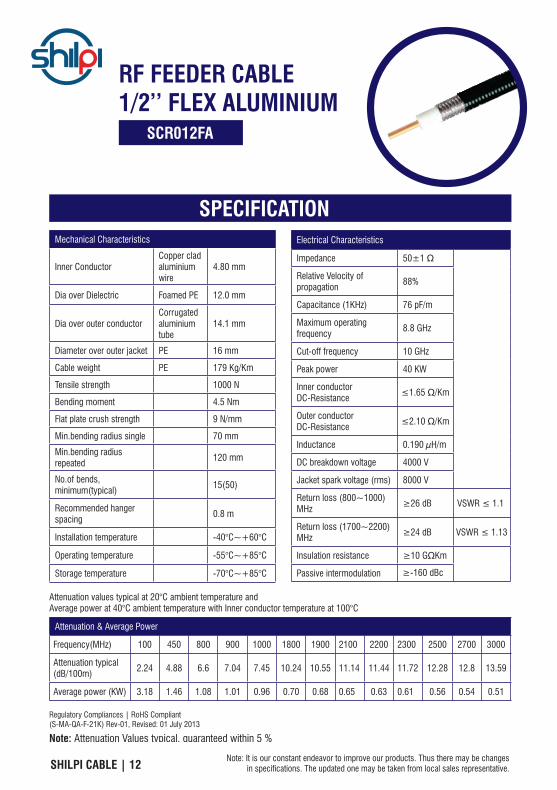
RF FEEDER CABLE1/2’’ FLEX ALUMINIUM
SCR012FA
RF FEEDER CABLE 1/2” SUPER FLEX ALUMINIUM
SCR012SA
Electrical Characteristics
Impedance 50±1 Ω
Relative Velocity of propagation
82%
Capacitance (1KHz) 80 pF/m
Maximum operating frequency
10.2 GHz
Cut-off frequency 13.0 GHz
Peak power 19 KW
Inner conductor DC-Resistance
≤2.8 Ω/Km
Outer conductor DC-Resistance
≤3.1 Ω/Km
Inductance 0.200 μH/m
DC breakdown voltage 2500 V
Jacket spark voltage (rms) 5000 V
Return loss (800~1000) MHz
≥26 dB VSWR ≤ 1.1
Return loss (1700~2200) MHz
≥24 dB VSWR ≤ 1.13
Insulation resistance ≥10 GΩKm
Passive intermodulation ≥160 dBc
Mechanical Characteristics
Inner ConductorCopper clad aluminium wire
3.55 mm
Dia over Dielectric Foamed PE 9.0 mm
Dia over outer conductorCorrugated aluminium tube
12.35 mm
Diameter over outer jacket PE 13.5 mm
Cable weight PE 139 Kg/Km
Tensile strength 800 N
Bending moment 3 Nm
Flat plate crush strength 7 N/mm
Min.bending radius single 15 mm
Min.bending radius repeated
30 mm
No.of bends, minimum(typical)
20(50)
Recommended hanger spacing
0.8 m
Installation temperature -40°C~+60°C
Operating temperature -55°C~+85°C
Storage temperature -70°C~+85°C
Attenuation & Average Power
Frequency(MHz) 100 450 800 900 1000 1800 1900 2100 2200 2300 2500 2700 3000
Attenuation typical (dB/100m)
3.42 7.39 9.96 10.6 11.2 15.28 15.72 16.6 17 17.4 18.2 19 20
Average power (KW) 2.46 1.14 0.84 0.79 0.75 0.55 0.53 0.50 0.49 0.48 0.46 0.44 0.42
SPECIFICATION
Attenuation values typical at 20°C ambient temperature andAverage power at 40°C ambient temperature with Inner conductor temperature at 100°C
Note: Attenuation Values typical, guaranteed within 5 %
Regulatory Compliances | RoHS Compliant(S-MA-QA-F-21L) Rev-01, Revised: 01 July 2013 01 Jan 2007
10 | SHILPI CABLESHILPI CABLE |
RF FEEDER CABLE1/2” FLEX ALUMINIUM
SCR012FA
Electrical Characteristics
Impedance 50±1 Ω
Relative Velocity of propagation
88%
Capacitance (1KHz) 76 pF/m
Maximum operating frequency
8.8 GHz
Cut-off frequency 10 GHz
Peak power 40 KW
Inner conductor DC-Resistance
≤1.65 Ω/Km
Outer conductor DC-Resistance
≤2.10 Ω/Km
Inductance 0.190 μH/m
DC breakdown voltage 4000 V
Jacket spark voltage (rms) 8000 V
Return loss (800~1000) MHz
≥26 dB VSWR ≤ 1.1
Return loss (1700~2200) MHz
≥24 dB VSWR ≤ 1.13
Insulation resistance ≥10 GΩKm
Passive intermodulation ≥160 dBc
Mechanical Characteristics
Inner ConductorCopper clad aluminium wire
4.80 mm
Dia over Dielectric Foamed PE 12.0 mm
Dia over outer conductorCorrugated aluminium tube
14.1 mm
Diameter over outer jacket PE 16 mm
Cable weight PE 179 Kg/Km
Tensile strength 1000 N
Bending moment 4.5 Nm
Flat plate crush strength 9 N/mm
Min.bending radius single 70 mm
Min.bending radius repeated
120 mm
No.of bends, minimum(typical)
15(50)
Recommended hanger spacing
0.8 m
Installation temperature -40°C~+60°C
Operating temperature -55°C~+85°C
Storage temperature -70°C~+85°C
Attenuation & Average Power
Frequency(MHz) 100 450 800 900 1000 1800 1900 2100 2200 2300 2500 2700 3000
Attenuation typical (dB/100m)
2.24 4.88 6.6 7.04 7.45 10.24 10.55 11.14 11.44 11.72 12.28 12.8 13.59
Average power (KW) 3.18 1.46 1.08 1.01 0.96 0.70 0.68 0.65 0.63 0.61 0.56 0.54 0.51
SPECIFICATION
Attenuation values typical at 20°C ambient temperature andAverage power at 40°C ambient temperature with Inner conductor temperature at 100°C
Regulatory Compliances | RoHS Compliant(S-MA-QA-F-21K) Rev-01, Revised: 01 July 2013 01 Jan 2007
Note: Attenuation Values typical, guaranteed within 5 %
09
≥-160dBc
13 | SHILPI CABLE Note: It is our constant endeavor to improve our products. Thus there may be changes in specifications. The updated one may be taken from local sales representative.
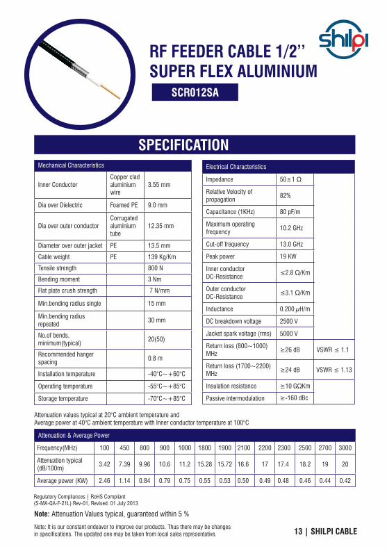
RF FEEDER CABLE 1/2’’ SUPER FLEX ALUMINIUM
SCR012SA
RF FEEDER CABLE 1/2” SUPER FLEX ALUMINIUM
SCR012SA
Electrical Characteristics
Impedance 50±1 Ω
Relative Velocity of propagation
82%
Capacitance (1KHz) 80 pF/m
Maximum operating frequency
10.2 GHz
Cut-off frequency 13.0 GHz
Peak power 19 KW
Inner conductor DC-Resistance
≤2.8 Ω/Km
Outer conductor DC-Resistance
≤3.1 Ω/Km
Inductance 0.200 μH/m
DC breakdown voltage 2500 V
Jacket spark voltage (rms) 5000 V
Return loss (800~1000) MHz
≥26 dB VSWR ≤ 1.1
Return loss (1700~2200) MHz
≥24 dB VSWR ≤ 1.13
Insulation resistance ≥10 GΩKm
Passive intermodulation ≥160 dBc
Mechanical Characteristics
Inner ConductorCopper clad aluminium wire
3.55 mm
Dia over Dielectric Foamed PE 9.0 mm
Dia over outer conductorCorrugated aluminium tube
12.35 mm
Diameter over outer jacket PE 13.5 mm
Cable weight PE 139 Kg/Km
Tensile strength 800 N
Bending moment 3 Nm
Flat plate crush strength 7 N/mm
Min.bending radius single 15 mm
Min.bending radius repeated
30 mm
No.of bends, minimum(typical)
20(50)
Recommended hanger spacing
0.8 m
Installation temperature -40°C~+60°C
Operating temperature -55°C~+85°C
Storage temperature -70°C~+85°C
Attenuation & Average Power
Frequency(MHz) 100 450 800 900 1000 1800 1900 2100 2200 2300 2500 2700 3000
Attenuation typical (dB/100m)
3.42 7.39 9.96 10.6 11.2 15.28 15.72 16.6 17 17.4 18.2 19 20
Average power (KW) 2.46 1.14 0.84 0.79 0.75 0.55 0.53 0.50 0.49 0.48 0.46 0.44 0.42
SPECIFICATION
Attenuation values typical at 20°C ambient temperature andAverage power at 40°C ambient temperature with Inner conductor temperature at 100°C
Note: Attenuation Values typical, guaranteed within 5 %
Regulatory Compliances | RoHS Compliant(S-MA-QA-F-21L) Rev-01, Revised: 01 July 2013 01 Jan 2007
10 | SHILPI CABLE
≥-160dBc
SHILPI CABLE |
RF FEEDER CABLE1/2” FLEX ALUMINIUM
SCR012FA
Electrical Characteristics
Impedance 50±1 Ω
Relative Velocity of propagation
88%
Capacitance (1KHz) 76 pF/m
Maximum operating frequency
8.8 GHz
Cut-off frequency 10 GHz
Peak power 40 KW
Inner conductor DC-Resistance
≤1.65 Ω/Km
Outer conductor DC-Resistance
≤2.10 Ω/Km
Inductance 0.190 μH/m
DC breakdown voltage 4000 V
Jacket spark voltage (rms) 8000 V
Return loss (800~1000) MHz
≥26 dB VSWR ≤ 1.1
Return loss (1700~2200) MHz
≥24 dB VSWR ≤ 1.13
Insulation resistance ≥10 GΩKm
Passive intermodulation ≥160 dBc
Mechanical Characteristics
Inner ConductorCopper clad aluminium wire
4.80 mm
Dia over Dielectric Foamed PE 12.0 mm
Dia over outer conductorCorrugated aluminium tube
14.1 mm
Diameter over outer jacket PE 16 mm
Cable weight PE 179 Kg/Km
Tensile strength 1000 N
Bending moment 4.5 Nm
Flat plate crush strength 9 N/mm
Min.bending radius single 70 mm
Min.bending radius repeated
120 mm
No.of bends, minimum(typical)
15(50)
Recommended hanger spacing
0.8 m
Installation temperature -40°C~+60°C
Operating temperature -55°C~+85°C
Storage temperature -70°C~+85°C
Attenuation & Average Power
Frequency(MHz) 100 450 800 900 1000 1800 1900 2100 2200 2300 2500 2700 3000
Attenuation typical (dB/100m)
2.24 4.88 6.6 7.04 7.45 10.24 10.55 11.14 11.44 11.72 12.28 12.8 13.59
Average power (KW) 3.18 1.46 1.08 1.01 0.96 0.70 0.68 0.65 0.63 0.61 0.56 0.54 0.51
SPECIFICATION
Attenuation values typical at 20°C ambient temperature andAverage power at 40°C ambient temperature with Inner conductor temperature at 100°C
Regulatory Compliances | RoHS Compliant(S-MA-QA-F-21K) Rev-01, Revised: 01 July 2013 01 Jan 2007
Note: Attenuation Values typical, guaranteed within 5 %
09

SHILPI CABLE | 14Note: It is our constant endeavor to improve our products. Thus there may be changes
in specifications. The updated one may be taken from local sales representative.
RF FEEDER CABLE7/8’’ FLEX
SCR078FC
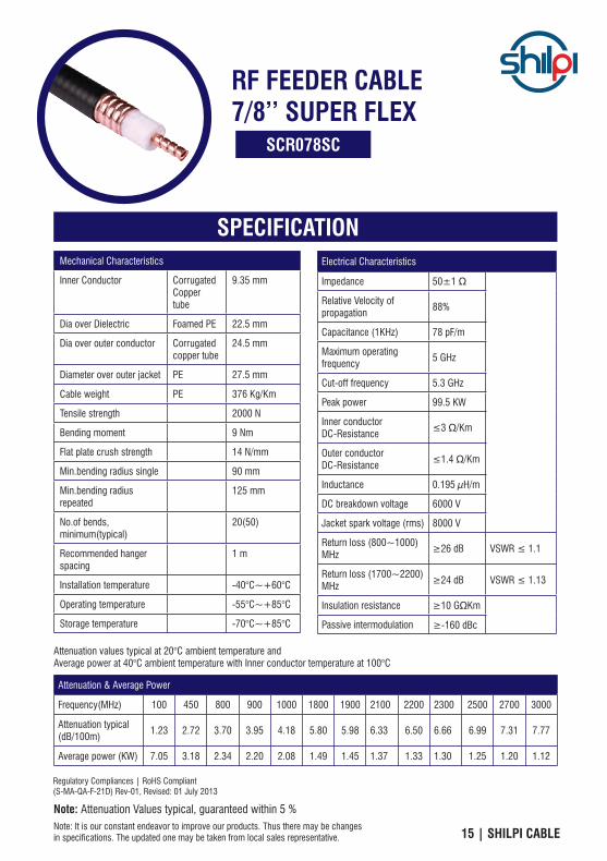
RF FEEDER CABLE7/8’’ SUPER FLEX
SCR078SC
Electrical Characteristics
Impedance 50±1 Ω
Relative Velocity of propagation
88%
Capacitance (1KHz) 78 pF/m
Maximum operating frequency
5 GHz
Cut-off frequency 5.3 GHz
Peak power 99.5 KW
Inner conductor DC-Resistance
≤3 Ω/Km
Outer conductor DC-Resistance
≤1.4 Ω/Km
Inductance 0.195 μH/m
DC breakdown voltage 6000 V
Jacket spark voltage (rms) 8000 V
Return loss (800~1000) MHz
≥26 dB VSWR ≤ 1.1
Return loss (1700~2200) MHz
≥24 dB VSWR ≤ 1.13
Insulation resistance ≥10 GΩKm
Passive intermodulation ≥160 dBc
Mechanical Characteristics
Inner Conductor Corrugated Copper tube
9.35 mm
Dia over Dielectric Foamed PE 22.5 mm
Dia over outer conductor Corrugated copper tube
24.5 mm
Diameter over outer jacket PE 27.5 mm
Cable weight PE 376 Kg/Km
Tensile strength 2000 N
Bending moment 9 Nm
Flat plate crush strength 14 N/mm
Min.bending radius single 90 mm
Min.bending radius repeated
125 mm
No.of bends, minimum(typical)
20(50)
Recommended hanger spacing
1 m
Installation temperature -40°C~+60°C
Operating temperature -55°C~+85°C
Storage temperature -70°C~+85°C
Attenuation & Average Power
Frequency(MHz) 100 450 800 900 1000 1800 1900 2100 2200 2300 2500 2700 3000
Attenuation typical (dB/100m)
1.23 2.72 3.70 3.95 4.18 5.80 5.98 6.33 6.50 6.66 6.99 7.31 7.77
Average power (KW) 7.05 3.18 2.34 2.20 2.08 1.49 1.45 1.37 1.33 1.30 1.25 1.20 1.12
SPECIFICATION
Attenuation values typical at 20°C ambient temperature andAverage power at 40°C ambient temperature with Inner conductor temperature at 100°C
Note: Attenuation Values typical, guaranteed within 5 %
Regulatory Compliances | RoHS Compliant(S-MA-QA-F-21D) Rev-01, Revised: 01 July 2013 01 Jan 2007
12 | SHILPI CABLE
RF FEEDER CABLE7/8’’ FLEX
SCR078FC
Electrical Characteristics
Impedance 50±1 Ω
Relative Velocity of propagation
87%
Capacitance (1KHz) 76.5 pF/m
Maximum operating frequency
5 GHz
Cut-off frequency 5.2 GHz
Peak power 90 KW
Inner conductor DC-Resistance
≤2.0 Ω/Km
Outer conductor DC-Resistance
≤1.4 Ω/Km
Inductance 0.191 μH/m
DC breakdown voltage 6000 V
Jacket spark voltage (rms) 8000 V
Return loss (800~1000) MHz
≥26 dB VSWR ≤ 1.1
Return loss (1700~2200) MHz
≥24 dB VSWR ≤ 1.13
Insulation resistance ≥10 GΩKm
Passive intermodulation ≥160 dBc
Mechanical Characteristics
Inner Conductor Copper tube 9.1 mm
Dia over Dielectric Foamed PE 22.5 mm
Dia over outer conductorCorrugated copper tube
24.5 mm
Diameter over outer jacket PE 27.5 mm
Cable weight PE 400 Kg/Km
Tensile strength 2000 N
Bending moment 18 Nm
Flat plate crush strength 14 N/mm
Min.bending radius single 120 mm
Min.bending radius repeated
240 mm
No.of bends, minimum(typical)
15(50)
Recommended hanger spacing
1.0 m
Installation temperature -40°C~+60°C
Operating temperature -55°C~+85°C
Storage temperature -70°C~+85°C
SPECIFICATION
Attenuation values typical at 20°C ambient temperature andAverage power at 40°C ambient temperature with Inner conductor temperature at 100°C
Attenuation & Average Power
Frequency(MHz) 100 450 800 900 1000 1800 1900 2100 2200 2300 2500 2700 3000
Attenuation typical (dB/100m)
1.2 2.6 3.6 3.8 4 5.6 5.8 6.13 6.3 6.47 6.8 7.1 7.5
Average power (KW) 9.1 3.96 2.82 2.62 2.46 1.70 1.64 1.53 1.50 1.46 1.38 1.31 1.22
Regulatory Compliances | RoHS Compliant(S-MA-QA-F-21K) Rev-01, Revised: 01 July 2013 01 Jan 2007
Note: Attenuation Values typical, guaranteed within 5 %
SHILPI CABLE | 11
≥-160dBc
15 | SHILPI CABLE Note: It is our constant endeavor to improve our products. Thus there may be changes in specifications. The updated one may be taken from local sales representative.
RF FEEDER CABLE 7/8’’ SUPER FLEX
SCR078SC
RF FEEDER CABLE7/8’’ SUPER FLEX
SCR078SC
Electrical Characteristics
Impedance 50±1 Ω
Relative Velocity of propagation
88%
Capacitance (1KHz) 78 pF/m
Maximum operating frequency
5 GHz
Cut-off frequency 5.3 GHz
Peak power 99.5 KW
Inner conductor DC-Resistance
≤3 Ω/Km
Outer conductor DC-Resistance
≤1.4 Ω/Km
Inductance 0.195 μH/m
DC breakdown voltage 6000 V
Jacket spark voltage (rms) 8000 V
Return loss (800~1000) MHz
≥26 dB VSWR ≤ 1.1
Return loss (1700~2200) MHz
≥24 dB VSWR ≤ 1.13
Insulation resistance ≥10 GΩKm
Passive intermodulation ≥160 dBc
Mechanical Characteristics
Inner Conductor Corrugated Copper tube
9.35 mm
Dia over Dielectric Foamed PE 22.5 mm
Dia over outer conductor Corrugated copper tube
24.5 mm
Diameter over outer jacket PE 27.5 mm
Cable weight PE 376 Kg/Km
Tensile strength 2000 N
Bending moment 9 Nm
Flat plate crush strength 14 N/mm
Min.bending radius single 90 mm
Min.bending radius repeated
125 mm
No.of bends, minimum(typical)
20(50)
Recommended hanger spacing
1 m
Installation temperature -40°C~+60°C
Operating temperature -55°C~+85°C
Storage temperature -70°C~+85°C
Attenuation & Average Power
Frequency(MHz) 100 450 800 900 1000 1800 1900 2100 2200 2300 2500 2700 3000
Attenuation typical (dB/100m)
1.23 2.72 3.70 3.95 4.18 5.80 5.98 6.33 6.50 6.66 6.99 7.31 7.77
Average power (KW) 7.05 3.18 2.34 2.20 2.08 1.49 1.45 1.37 1.33 1.30 1.25 1.20 1.12
SPECIFICATION
Attenuation values typical at 20°C ambient temperature andAverage power at 40°C ambient temperature with Inner conductor temperature at 100°C
Note: Attenuation Values typical, guaranteed within 5 %
Regulatory Compliances | RoHS Compliant(S-MA-QA-F-21D) Rev-01, Revised: 01 July 2013 01 Jan 2007
12 | SHILPI CABLE
≥-160dBc
RF FEEDER CABLE7/8’’ FLEX
SCR078FC
Electrical Characteristics
Impedance 50±1 Ω
Relative Velocity of propagation
87%
Capacitance (1KHz) 76.5 pF/m
Maximum operating frequency
5 GHz
Cut-off frequency 5.2 GHz
Peak power 90 KW
Inner conductor DC-Resistance
≤2.0 Ω/Km
Outer conductor DC-Resistance
≤1.4 Ω/Km
Inductance 0.191 μH/m
DC breakdown voltage 6000 V
Jacket spark voltage (rms) 8000 V
Return loss (800~1000) MHz
≥26 dB VSWR ≤ 1.1
Return loss (1700~2200) MHz
≥24 dB VSWR ≤ 1.13
Insulation resistance ≥10 GΩKm
Passive intermodulation ≥160 dBc
Mechanical Characteristics
Inner Conductor Copper tube 9.1 mm
Dia over Dielectric Foamed PE 22.5 mm
Dia over outer conductorCorrugated copper tube
24.5 mm
Diameter over outer jacket PE 27.5 mm
Cable weight PE 400 Kg/Km
Tensile strength 2000 N
Bending moment 18 Nm
Flat plate crush strength 14 N/mm
Min.bending radius single 120 mm
Min.bending radius repeated
240 mm
No.of bends, minimum(typical)
15(50)
Recommended hanger spacing
1.0 m
Installation temperature -40°C~+60°C
Operating temperature -55°C~+85°C
Storage temperature -70°C~+85°C
SPECIFICATION
Attenuation values typical at 20°C ambient temperature andAverage power at 40°C ambient temperature with Inner conductor temperature at 100°C
Attenuation & Average Power
Frequency(MHz) 100 450 800 900 1000 1800 1900 2100 2200 2300 2500 2700 3000
Attenuation typical (dB/100m)
1.2 2.6 3.6 3.8 4 5.6 5.8 6.13 6.3 6.47 6.8 7.1 7.5
Average power (KW) 9.1 3.96 2.82 2.62 2.46 1.70 1.64 1.53 1.50 1.46 1.38 1.31 1.22
Regulatory Compliances | RoHS Compliant(S-MA-QA-F-21K) Rev-01, Revised: 01 July 2013 01 Jan 2007
Note: Attenuation Values typical, guaranteed within 5 %
SHILPI CABLE | 11
SHILPI CABLE | 16Note: It is our constant endeavor to improve our products. Thus there may be changes
in specifications. The updated one may be taken from local sales representative.
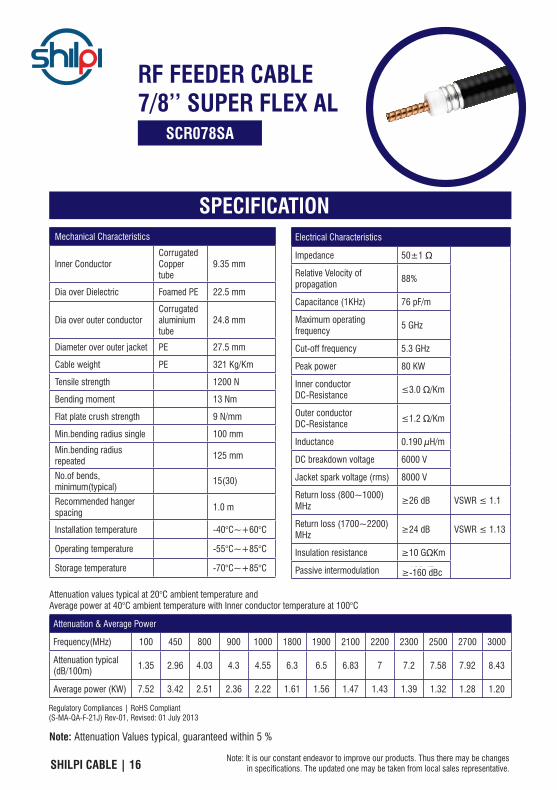
RF FEEDER CABLE7/8’’ SUPER FLEX AL
SCR078SA
RF FEEDER CABLE7/8’’ LOW LOSS
SCR078FC-LL
Electrical Characteristics
Impedance 50±1 Ω
Relative Velocity of propagation
87%
Capacitance (1KHz) 76.5 pF/m
Maximum operating frequency
5 GHz
Cut-off frequency 5.2 GHz
Peak power 90 KW
Inner conductor DC-Resistance
≤1.92 Ω/Km
Outer conductor DC-Resistance
≤1.4 Ω/Km
Inductance 0.191 μH/m
DC breakdown voltage 4000 V
Jacket spark voltage (rms) 8000 V
Return loss (800~1000) MHz
≥26 dB VSWR ≤ 1.1
Return loss (1700~2200) MHz
≥24 dB VSWR ≤ 1.13
Insulation resistance ≥10 GΩKm
Passive intermodulation ≥160 dBc
Mechanical Characteristics
Inner Conductor Copper tube 9.3 mm
Dia over Dielectric Foamed PE 22.5 mm
Dia over outer conductorCorrugated copper tube
24.9 mm
Diameter over outer jacket PE 27.5 mm
Cable weight PE 424 Kg/Km
Tensile strength 2000 N
Bending moment 18 Nm
Flat plate crush strength 14 N/mm
Min.bending radius single 120 mm
Min.bending radius repeated
240 mm
No.of bends, minimum(typical)
15(50)
Recommended hanger spacing
1 m
Installation temperature -40°C~+60°C
Operating temperature -55°C~+85°C
Storage temperature -70°C~+85°C
Attenuation & Average Power
Frequency(MHz) 100 450 800 900 1000 1800 1900 2100 2200 2300 2500 2700 3000
Attenuation typical (dB/100m)
1.11 2.44 3.32 3.54 3.75 5.19 5.35 5.66 5.81 5.96 6.25 6.53 6.97
Average power (KW) 9.17 3.96 2.82 2.62 2.46 1.70 1.64 1.55 1.50 1.46 1.38 1.31 1.22
SPECIFICATION
Attenuation values typical at 20°C ambient temperature andAverage power at 40°C ambient temperature with Inner conductor temperature at 100°C
Note: Attenuation Values typical, guaranteed within 5 %
Regulatory Compliances | RoHS Compliant(S-MA-QA-F-21G) Rev-01, Revised: 01 July 2013 01 Jan 2007
15 | SHILPI CABLE
SCR078SA
Electrical Characteristics
Impedance 50±1 Ω
Relative Velocity of propagation
88%
Capacitance (1KHz) 76 pF/m
Maximum operating frequency
5 GHz
Cut-off frequency 5.3 GHz
Peak power 80 KW
Inner conductor DC-Resistance
≤3.0 Ω/Km
Outer conductor DC-Resistance
≤1.2 Ω/Km
Inductance 0.190 μH/m
DC breakdown voltage 6000 V
Jacket spark voltage (rms) 8000 V
Return loss (800~1000) MHz
≥26 dB VSWR ≤ 1.1
Return loss (1700~2200) MHz
≥24 dB VSWR ≤ 1.13
Insulation resistance ≥10 GΩKm
Passive intermodulation ≥160 dBc
Mechanical Characteristics
Inner ConductorCorrugated Copper tube
9.35 mm
Dia over Dielectric Foamed PE 22.5 mm
Dia over outer conductorCorrugated aluminium tube
24.8 mm
Diameter over outer jacket PE 27.5 mm
Cable weight PE 321 Kg/Km
Tensile strength 1200 N
Bending moment 13 Nm
Flat plate crush strength 9 N/mm
Min.bending radius single 100 mm
Min.bending radius repeated
125 mm
No.of bends, minimum(typical)
Recommended hanger spacing
1.0 m
Installation temperature -40°C~+60°C
Operating temperature -55°C~+85°C
Storage temperature -70°C~+85°C
Attenuation & Average Power
Frequency(MHz) 100 450 800 900 1000 1800 1900 2100 2200 2300 2500 2700 3000
Attenuation typical (dB/100m)
1.35 2.96 4.03 4.3 4.55 6.3 6.5 6.83 7 7.2 7.58 7.92 8.43
Average power (KW) 7.52 3.42 2.51 2.36 2.22 1.61 1.56 1.47 1.43 1.39 1.32 1.28 1.20
SPECIFICATION
Attenuation values typical at 20°C ambient temperature andAverage power at 40°C ambient temperature with Inner conductor temperature at 100°C
Note: Attenuation Values typical, guaranteed within 5 %
Regulatory Compliances | RoHS Compliant(S-MA-QA-F-21J) Rev-01, Revised: 01 July 2013 01 Jan 2007
RF FEEDER CABLE7/8’’ SUPER FLEX ALUMINUM
15(30)
14 | SHILPI CABLE
≥-160dBc

17 | SHILPI CABLE Note: It is our constant endeavor to improve our products. Thus there may be changes in specifications. The updated one may be taken from local sales representative.
RF FEEDER CABLE 7/8’’ LOW LOSS
SCR078FC-LL
RF FEEDER CABLE7/8’’ LOW LOSS
SCR078FC-LL
Electrical Characteristics
Impedance 50±1 Ω
Relative Velocity of propagation
87%
Capacitance (1KHz) 76.5 pF/m
Maximum operating frequency
5 GHz
Cut-off frequency 5.2 GHz
Peak power 90 KW
Inner conductor DC-Resistance
≤1.92 Ω/Km
Outer conductor DC-Resistance
≤1.4 Ω/Km
Inductance 0.191 μH/m
DC breakdown voltage 4000 V
Jacket spark voltage (rms) 8000 V
Return loss (800~1000) MHz
≥26 dB VSWR ≤ 1.1
Return loss (1700~2200) MHz
≥24 dB VSWR ≤ 1.13
Insulation resistance ≥10 GΩKm
Passive intermodulation ≥160 dBc
Mechanical Characteristics
Inner Conductor Copper tube 9.3 mm
Dia over Dielectric Foamed PE 22.5 mm
Dia over outer conductorCorrugated copper tube
24.9 mm
Diameter over outer jacket PE 27.5 mm
Cable weight PE 424 Kg/Km
Tensile strength 2000 N
Bending moment 18 Nm
Flat plate crush strength 14 N/mm
Min.bending radius single 120 mm
Min.bending radius repeated
240 mm
No.of bends, minimum(typical)
15(50)
Recommended hanger spacing
1 m
Installation temperature -40°C~+60°C
Operating temperature -55°C~+85°C
Storage temperature -70°C~+85°C
Attenuation & Average Power
Frequency(MHz) 100 450 800 900 1000 1800 1900 2100 2200 2300 2500 2700 3000
Attenuation typical (dB/100m)
1.11 2.44 3.32 3.54 3.75 5.19 5.35 5.66 5.81 5.96 6.25 6.53 6.97
Average power (KW) 9.17 3.96 2.82 2.62 2.46 1.70 1.64 1.55 1.50 1.46 1.38 1.31 1.22
SPECIFICATION
Attenuation values typical at 20°C ambient temperature andAverage power at 40°C ambient temperature with Inner conductor temperature at 100°C
Note: Attenuation Values typical, guaranteed within 5 %
Regulatory Compliances | RoHS Compliant(S-MA-QA-F-21G) Rev-01, Revised: 01 July 2013 01 Jan 2007
15 | SHILPI CABLE
≥-160dBc
SCR078SA
Electrical Characteristics
Impedance 50±1 Ω
Relative Velocity of propagation
88%
Capacitance (1KHz) 76 pF/m
Maximum operating frequency
5 GHz
Cut-off frequency 5.3 GHz
Peak power 80 KW
Inner conductor DC-Resistance
≤3.0 Ω/Km
Outer conductor DC-Resistance
≤1.2 Ω/Km
Inductance 0.190 μH/m
DC breakdown voltage 6000 V
Jacket spark voltage (rms) 8000 V
Return loss (800~1000) MHz
≥26 dB VSWR ≤ 1.1
Return loss (1700~2200) MHz
≥24 dB VSWR ≤ 1.13
Insulation resistance ≥10 GΩKm
Passive intermodulation ≥160 dBc
Mechanical Characteristics
Inner ConductorCorrugated Copper tube
9.35 mm
Dia over Dielectric Foamed PE 22.5 mm
Dia over outer conductorCorrugated aluminium tube
24.8 mm
Diameter over outer jacket PE 27.5 mm
Cable weight PE 321 Kg/Km
Tensile strength 1200 N
Bending moment 13 Nm
Flat plate crush strength 9 N/mm
Min.bending radius single 100 mm
Min.bending radius repeated
125 mm
No.of bends, minimum(typical)
Recommended hanger spacing
1.0 m
Installation temperature -40°C~+60°C
Operating temperature -55°C~+85°C
Storage temperature -70°C~+85°C
Attenuation & Average Power
Frequency(MHz) 100 450 800 900 1000 1800 1900 2100 2200 2300 2500 2700 3000
Attenuation typical (dB/100m)
1.35 2.96 4.03 4.3 4.55 6.3 6.5 6.83 7 7.2 7.58 7.92 8.43
Average power (KW) 7.52 3.42 2.51 2.36 2.22 1.61 1.56 1.47 1.43 1.39 1.32 1.28 1.20
SPECIFICATION
Attenuation values typical at 20°C ambient temperature andAverage power at 40°C ambient temperature with Inner conductor temperature at 100°C
Note: Attenuation Values typical, guaranteed within 5 %
Regulatory Compliances | RoHS Compliant(S-MA-QA-F-21J) Rev-01, Revised: 01 July 2013 01 Jan 2007
RF FEEDER CABLE7/8’’ SUPER FLEX ALUMINUM
15(30)
14 | SHILPI CABLE
SHILPI CABLE | 18Note: It is our constant endeavor to improve our products. Thus there may be changes
in specifications. The updated one may be taken from local sales representative.
RF FEEDER CABLE1 5/8’’ FLEX
SCR158SC
Electrical Characteristics
Impedance 50±1 Ω
Relative Velocity of propagation
88%
Capacitance (1KHz) 76 pF/m
Maximum operating frequency
2.7 GHz
Cut-off frequency 3 GHz
Peak power 290 KW
Inner conductor DC-Resistance
≤1.5 Ω/Km
Outer conductor DC-Resistance
≤0.5 Ω/Km
Inductance 0.190 μH/m
DC breakdown voltage 7000 V
Jacket spark voltage (rms) 10000 V
Return loss (800~1000) MHz
≥26 dB VSWR ≤ 1.1
Return loss (1700~2200) MHz
≥24 dB VSWR ≤ 1.13
Insulation resistance ≥10 GΩKm
Passive intermodulation ≥160 dBc
Mechanical Characteristics
Inner ConductorCorrugated copper tube
17.3 mm
Dia over Dielectric Foamed PE 43 mm
Dia over outer conductorCorrugated copper tube
46.4 mm
Diameter over outer jacket PE 50 mm
Cable weight PE 1075 Kg/Km
Tensile strength 2000 N
Bending moment 68 Nm
Flat plate crush strength 20 N/mm
Min.bending radius single 300 mm
Min.bending radius repeated
510 mm
No.of bends, minimum(typical)
15(50)
Recommended hanger spacing
1.2 m
Installation temperature -40°C~+60°C
Operating temperature -55°C~+85°C
Storage temperature -70°C~+85°C
Attenuation & Average Power
Frequency(MHz) 100 450 800 900 1000 1800 1900 2100 2200 2300 2500 2700 3000
Attenuation typical (dB/100m)
0.68 1.55 2.17 2.33 2.48 3.56 3.69 3.93 4.05 4.16 4.40 4.60 --
Average power (KW) 18.9 7.73 5.35 4.95 4.62 3.09 2.97 2.78 2.68 2.60 2.45 2.30 --
SPECIFICATION
Attenuation values typical at 20°C ambient temperature andAverage power at 40°C ambient temperature with Inner conductor temperature at 100°C
Note: Attenuation Values typical, guaranteed within 5 %
Regulatory Compliances | RoHS Compliant(S-MA-QA-F-21P) Rev-01, Revised: 01 July 2013 01 Jan 2007
17 | SHILPI CABLE
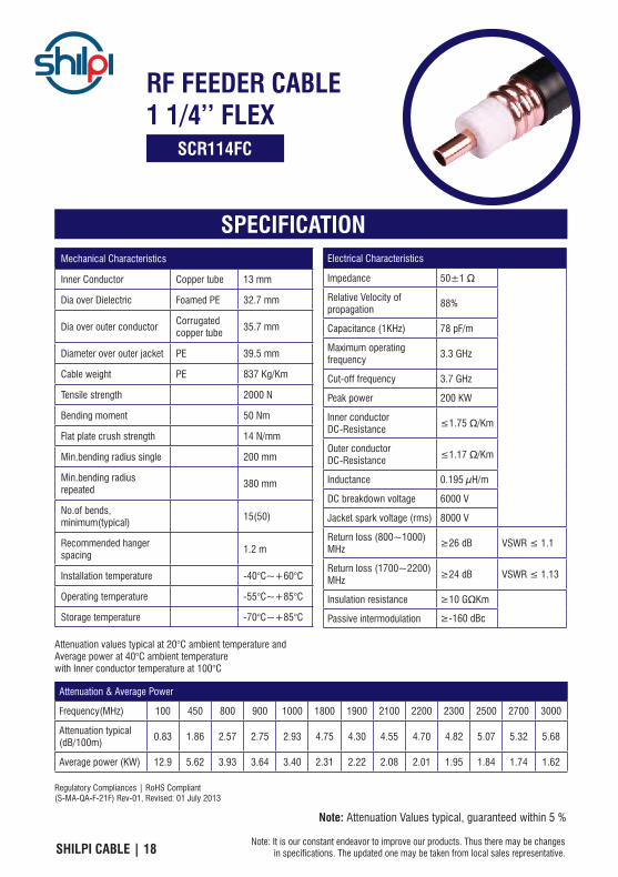
RF FEEDER CABLE1 1/4’’ FLEX
SCR114FC
SHILPI CABLE |
RF FEEDER CABLE1 1/4’’ FLEX
SCR114FC
Electrical Characteristics
Impedance 50±1 Ω
Relative Velocity of propagation
88%
Capacitance (1KHz) 78 pF/m
Maximum operating frequency
3.3 GHz
Cut-off frequency 3.7 GHz
Peak power 200 KW
Inner conductor DC-Resistance
≤1.75 Ω/Km
Outer conductor DC-Resistance
Inductance 0.195 μH/m
DC breakdown voltage 6000 V
Jacket spark voltage (rms) 8000 V
Return loss (800~1000) MHz
≥26 dB VSWR ≤ 1.1
Return loss (1700~2200) MHz
≥24 dB VSWR ≤ 1.13
Insulation resistance ≥10 GΩKm
Passive intermodulation ≥160 dBc
Mechanical Characteristics
Inner Conductor Copper tube 13 mm
Dia over Dielectric Foamed PE 32.7 mm
Dia over outer conductorCorrugated copper tube
35.7 mm
Diameter over outer jacket PE 39.5 mm
Cable weight PE 837 Kg/Km
Tensile strength 2000 N
Bending moment 50 Nm
Flat plate crush strength 14 N/mm
Min.bending radius single 200 mm
Min.bending radius repeated
380 mm
No.of bends, minimum(typical)
15(50)
Recommended hanger spacing
1.2 m
Installation temperature -40°C~+60°C
Operating temperature -55°C~+85°C
Storage temperature -70°C~+85°C
SPECIFICATION
Attenuation values typical at 20°C ambient temperature andAverage power at 40°C ambient temperature with Inner conductor temperature at 100°C
Attenuation & Average Power
Frequency(MHz) 100 450 800 900 1000 1800 1900 2100 2200 2300 2500 2700 3000
Attenuation typical (dB/100m)
0.83 1.86 2.57 2.75 2.93 4.75 4.30 4.55 4.70 4.82 5.07 5.32 5.68
Average power (KW) 12.9 5.62 3.93 3.64 3.40 2.31 2.22 2.08 2.01 1.95 1.84 1.74 1.62
Regulatory Compliances | RoHS Compliant(S-MA-QA-F-21F) Rev-01, Revised: 01 July 2013 01 Jan 2007
Note: Attenuation Values typical, guaranteed within 5 %
≤1.17 Ω/Km
16
≥-160dBc

19 | SHILPI CABLE Note: It is our constant endeavor to improve our products. Thus there may be changes in specifications. The updated one may be taken from local sales representative.
RF FEEDER CABLE1 5/8’’ FLEX
SCR158SC
Electrical Characteristics
Impedance 50±1 Ω
Relative Velocity of propagation
88%
Capacitance (1KHz) 76 pF/m
Maximum operating frequency
2.7 GHz
Cut-off frequency 3 GHz
Peak power 290 KW
Inner conductor DC-Resistance
≤1.5 Ω/Km
Outer conductor DC-Resistance
≤0.5 Ω/Km
Inductance 0.190 μH/m
DC breakdown voltage 7000 V
Jacket spark voltage (rms) 10000 V
Return loss (800~1000) MHz
≥26 dB VSWR ≤ 1.1
Return loss (1700~2200) MHz
≥24 dB VSWR ≤ 1.13
Insulation resistance ≥10 GΩKm
Passive intermodulation ≥160 dBc
Mechanical Characteristics
Inner ConductorCorrugated copper tube
17.3 mm
Dia over Dielectric Foamed PE 43 mm
Dia over outer conductorCorrugated copper tube
46.4 mm
Diameter over outer jacket PE 50 mm
Cable weight PE 1075 Kg/Km
Tensile strength 2000 N
Bending moment 68 Nm
Flat plate crush strength 20 N/mm
Min.bending radius single 300 mm
Min.bending radius repeated
510 mm
No.of bends, minimum(typical)
15(50)
Recommended hanger spacing
1.2 m
Installation temperature -40°C~+60°C
Operating temperature -55°C~+85°C
Storage temperature -70°C~+85°C
Attenuation & Average Power
Frequency(MHz) 100 450 800 900 1000 1800 1900 2100 2200 2300 2500 2700 3000
Attenuation typical (dB/100m)
0.68 1.55 2.17 2.33 2.48 3.56 3.69 3.93 4.05 4.16 4.40 4.60 --
Average power (KW) 18.9 7.73 5.35 4.95 4.62 3.09 2.97 2.78 2.68 2.60 2.45 2.30 --
SPECIFICATION
Attenuation values typical at 20°C ambient temperature andAverage power at 40°C ambient temperature with Inner conductor temperature at 100°C
Note: Attenuation Values typical, guaranteed within 5 %
Regulatory Compliances | RoHS Compliant(S-MA-QA-F-21P) Rev-01, Revised: 01 July 2013 01 Jan 2007
17 | SHILPI CABLE
≥-160dBc
RF FEEDER CABLE 1 5/8’’ FLEX
SCR158SC
SHILPI CABLE |
RF FEEDER CABLE1 1/4’’ FLEX
SCR114FC
Electrical Characteristics
Impedance 50±1 Ω
Relative Velocity of propagation
88%
Capacitance (1KHz) 78 pF/m
Maximum operating frequency
3.3 GHz
Cut-off frequency 3.7 GHz
Peak power 200 KW
Inner conductor DC-Resistance
≤1.75 Ω/Km
Outer conductor DC-Resistance
Inductance 0.195 μH/m
DC breakdown voltage 6000 V
Jacket spark voltage (rms) 8000 V
Return loss (800~1000) MHz
≥26 dB VSWR ≤ 1.1
Return loss (1700~2200) MHz
≥24 dB VSWR ≤ 1.13
Insulation resistance ≥10 GΩKm
Passive intermodulation ≥160 dBc
Mechanical Characteristics
Inner Conductor Copper tube 13 mm
Dia over Dielectric Foamed PE 32.7 mm
Dia over outer conductorCorrugated copper tube
35.7 mm
Diameter over outer jacket PE 39.5 mm
Cable weight PE 837 Kg/Km
Tensile strength 2000 N
Bending moment 50 Nm
Flat plate crush strength 14 N/mm
Min.bending radius single 200 mm
Min.bending radius repeated
380 mm
No.of bends, minimum(typical)
15(50)
Recommended hanger spacing
1.2 m
Installation temperature -40°C~+60°C
Operating temperature -55°C~+85°C
Storage temperature -70°C~+85°C
SPECIFICATION
Attenuation values typical at 20°C ambient temperature andAverage power at 40°C ambient temperature with Inner conductor temperature at 100°C
Attenuation & Average Power
Frequency(MHz) 100 450 800 900 1000 1800 1900 2100 2200 2300 2500 2700 3000
Attenuation typical (dB/100m)
0.83 1.86 2.57 2.75 2.93 4.75 4.30 4.55 4.70 4.82 5.07 5.32 5.68
Average power (KW) 12.9 5.62 3.93 3.64 3.40 2.31 2.22 2.08 2.01 1.95 1.84 1.74 1.62
Regulatory Compliances | RoHS Compliant(S-MA-QA-F-21F) Rev-01, Revised: 01 July 2013 01 Jan 2007
Note: Attenuation Values typical, guaranteed within 5 %
≤1.17 Ω/Km
16
Attenuation&AveragePower
Frequency(MHz) 100 450 800 900 1000 1800 1900 2100 2200 2300 2500 2700 3000
Attenuationtypical(dB/100m)
0.68 1.55 2.17 2.33 2.48 3.56 3.69 3.93 4.05 4.16 4.40 4.60 --
Averagepower(KW) 18.9 7.73 5.35 4.95 4.62 3.09 2.97 2.78 2.68 2.60 2.45 2.30 --
Attenuationvaluestypicalat20°CambienttemperatureandAveragepowerat40°Cambienttemperature withInnerconductortemperatureat100°C
Note:AttenuationValuestypical,guaranteedwithin5%
RegulatoryCompliances|RoHSCompliant(S-MA-QA-F-21P)Rev-01,Revised:01July201301Jan2007

SHILPI CABLE | 20Note: It is our constant endeavor to improve our products. Thus there may be changes
in specifications. The updated one may be taken from local sales representative.SHILPI CABLE | 20

21 | SHILPI CABLE Note: It is our constant endeavor to improve our products. Thus there may be changes in specifications. The updated one may be taken from local sales representative. 21 | SHILPI CABLE
RF CONNECTORSRF ADAPTORSRFconnectorisanelectricalconnectordesignedtoworkatradiofrequenciesinthemulti-megahertzrange.RFconnectorsaretypicallyusedwithRFcablesandaredesignedtomaintaintheshieldingthattheRFdesignoffers.StraightandRightAngleconnectorsareavailableinNtypeandDintypeforvarioussizes.

SHILPI CABLE | 22Note: It is our constant endeavor to improve our products. Thus there may be changes
in specifications. The updated one may be taken from local sales representative.SHILPI CABLE |
DIN (7/16)CONNECTORS
Model Type
SA158 CDM SA158 CDF SA114 CDM SA114 CDFSA 078 CDM
SA 078 CDF
SA 012 CDM
SA 012 CDF
DIN Type1 5/8” Male
1 5/8” Female1 1/4” Male
1 1/4” Female
7/8’ Male
7/8’ Female1/2” Male
1/2” Female
VSWR≤1.1 (0~2.2GHz)
≤1.1 (0~2.2GHz)
≤1.1 (0~2.2GHz)
≤1.1 (0~2.2GHz)
≤1.1 (0~3GHz)
≤1.1 (0~3GHz)
≤1.1 (0~3GHz)
≤1.1 (0~3GHz)
Suitable Cables
SHILPI 1 5/8”
SHILPI 1 5/8”
SHILPI 1 1/4”
SHILPI1 1/4”
SHILPI 7/8”
SHILPI 7/8”SHILPI 1/2”
SHILPI 1/2”
Packing 1Pc in box 1Pc in box 1Pc in box 1Pc in box 1Pc in box 1Pc in box 1Pc in box 1Pc in box
ELECTRICAL DATA
Impedance 50 Ω
Frequency DC-8.3GHz
Insertion Loss ≤0.05dB
Center Contact Resistance ≤0.4mΩ
Outer Contact Resistance ≤0.2mΩ
Insultation resistance ≥10000MΩ
Withstanding Voltage AC (v/min)
≥4000V
Power Handling1800W@1GHz800W@4GHz
RF Leakage 128dB@1GHz
Intermodulation (3rd order) ≤-153dBc@2x20W
Retention for all female Connectors
6~18N
Interface
According to IEC 60169-4, VG 95250, EN 122190, DIN 47233
Environmental Data
Temperature Range -40~+850C
Relative Moisture 90%~95%, Temprature: 40±20C
Water Proof IP67
Rapid Change of Temperature
DIN EN 122190, Clause 4.6.7
Corrosion DIN EN 122190, Clause 4.6.10
Vibration DIN EN 122190, Clause 4.6.3
Damp Heat DIN EN 122190, Clause 4.6.6
Climate Test DIN EN 122190, Clause 4.6.5(55/155/56)
Mechanical Data
Mating cycles min. 500
Coupling torque (recommended)
25Nm to 30Nm
Proof torque max. 35Nm
Material Plating
Connector Part Material Plating
Shell Brass Alloy
Center Contact Brass Silver
Back Nut Brass Alloy
Clamp Brass Alloy
Sealing Silicone rubber
Insulator PTFE (orTPX)
SPECIFICATION FOR DIN CONNECTORS
20
N CONNECTORS
Model Type
SA 158 CNM
SA 158 CNFSA 114 CNM
SA 114 CNFSA 078 CNM
SA 078 CNF
SA 012 CNM
SA 012 CNF
N Type1 5/8” Male
1 5/8” Female
1 1/4” Male
1 1/4” Female
7/8’ Male
7/8’ Female
1/2” Male
1/2” Female
VSWR ≤1.1 (0~2.2GHz)
≤1.1 (0~2.2GHz)
≤1.1 (0~2.2GHz)
≤1.1 (0~2.2GHz)
≤1.1 (0~3GHz)
≤1.1 (0~3GHz)
≤1.1 (0~3GHz)
≤1.1 (0~3GHz)
Suitable Cables
SHILPI 1 5/8”
SHILPI 1 5/8”
SHILPI 1 1/4”
SHILPI 1 1/4”
SHILPI 7/8”
SHILPI 7/8”
SHILPI 1/2”
SHILPI 1/2”
Packing 1Pc in box 1Pc in box 1Pc in box 1Pc in box 1Pc in box 1Pc in box 1Pc in box 1Pc in box
ELECTRICAL DATA
Impedance 50 Ω
Frequency DC-11GHz
Insertion Loss ≤0.05dB
Center Contact Resistance ≤1mΩ
Outer Contact Resistance ≤0.25mΩ
Insultation resistance ≥5000MΩ
Withstanding Voltage AC (v/min)
≥2500V
Power Handling1000W@10GHz700W@2GHz
RF Leakage 128dB@1GHz
Intermodulation (3rd order) ≤-150dBc@2x20W
Retention for all female Connectors
≥0.56 N
Interface
According to IEC 60169-4, MIL-PRF-39012, CECC22210
Environmental Data
Temperature Range -40~+850C
Relative Moisture 90%~95%, Temprature: 40±20C
Water Proof IP67
Corrosion MIL-STD-202, Meth.101,Cond.B
Vibration MIL-STD-202, Meth.204,Cond.B
Damp Heat MIL-STD-202, Meth.213,Cond.I
Climate Test MIL-STD-202, Meth.106
Mechanical Data
Mating cycles min. 500
Coupling torque (recommended)
0.7 Nm to 1.1 Nm
Proof torque max. 1.7 Nm
Material Plating
Connector Part Material Plating
Shell Brass Alloy
Center Contact Brass Silver
Back Nut Brass Alloy
Clamp Brass Alloy
Sealing Silicone rubber
Insulator PTFE (orTPX)
SPECIFICATION FOR N CONNECTORS
21 | SHILPI CABLE
DIN (7/16)CONNECTORS
SCR012FA

23 | SHILPI CABLE Note: It is our constant endeavor to improve our products. Thus there may be changes in specifications. The updated one may be taken from local sales representative.SHILPI CABLE |
DIN (7/16)CONNECTORS
Model Type
SA158 CDM SA158 CDF SA114 CDM SA114 CDFSA 078 CDM
SA 078 CDF
SA 012 CDM
SA 012 CDF
DIN Type1 5/8” Male
1 5/8” Female1 1/4” Male
1 1/4” Female
7/8’ Male
7/8’ Female1/2” Male
1/2” Female
VSWR≤1.1 (0~2.2GHz)
≤1.1 (0~2.2GHz)
≤1.1 (0~2.2GHz)
≤1.1 (0~2.2GHz)
≤1.1 (0~3GHz)
≤1.1 (0~3GHz)
≤1.1 (0~3GHz)
≤1.1 (0~3GHz)
Suitable Cables
SHILPI 1 5/8”
SHILPI 1 5/8”
SHILPI 1 1/4”
SHILPI1 1/4”
SHILPI 7/8”
SHILPI 7/8”SHILPI 1/2”
SHILPI 1/2”
Packing 1Pc in box 1Pc in box 1Pc in box 1Pc in box 1Pc in box 1Pc in box 1Pc in box 1Pc in box
ELECTRICAL DATA
Impedance 50 Ω
Frequency DC-8.3GHz
Insertion Loss ≤0.05dB
Center Contact Resistance ≤0.4mΩ
Outer Contact Resistance ≤0.2mΩ
Insultation resistance ≥10000MΩ
Withstanding Voltage AC (v/min)
≥4000V
Power Handling1800W@1GHz800W@4GHz
RF Leakage 128dB@1GHz
Intermodulation (3rd order) ≤-153dBc@2x20W
Retention for all female Connectors
6~18N
Interface
According to IEC 60169-4, VG 95250, EN 122190, DIN 47233
Environmental Data
Temperature Range -40~+850C
Relative Moisture 90%~95%, Temprature: 40±20C
Water Proof IP67
Rapid Change of Temperature
DIN EN 122190, Clause 4.6.7
Corrosion DIN EN 122190, Clause 4.6.10
Vibration DIN EN 122190, Clause 4.6.3
Damp Heat DIN EN 122190, Clause 4.6.6
Climate Test DIN EN 122190, Clause 4.6.5(55/155/56)
Mechanical Data
Mating cycles min. 500
Coupling torque (recommended)
25Nm to 30Nm
Proof torque max. 35Nm
Material Plating
Connector Part Material Plating
Shell Brass Alloy
Center Contact Brass Silver
Back Nut Brass Alloy
Clamp Brass Alloy
Sealing Silicone rubber
Insulator PTFE (orTPX)
SPECIFICATION FOR DIN CONNECTORS
20
N CONNECTORS
Model Type
SA 158 CNM
SA 158 CNFSA 114 CNM
SA 114 CNFSA 078 CNM
SA 078 CNF
SA 012 CNM
SA 012 CNF
N Type1 5/8” Male
1 5/8” Female
1 1/4” Male
1 1/4” Female
7/8’ Male
7/8’ Female
1/2” Male
1/2” Female
VSWR ≤1.1 (0~2.2GHz)
≤1.1 (0~2.2GHz)
≤1.1 (0~2.2GHz)
≤1.1 (0~2.2GHz)
≤1.1 (0~3GHz)
≤1.1 (0~3GHz)
≤1.1 (0~3GHz)
≤1.1 (0~3GHz)
Suitable Cables
SHILPI 1 5/8”
SHILPI 1 5/8”
SHILPI 1 1/4”
SHILPI 1 1/4”
SHILPI 7/8”
SHILPI 7/8”
SHILPI 1/2”
SHILPI 1/2”
Packing 1Pc in box 1Pc in box 1Pc in box 1Pc in box 1Pc in box 1Pc in box 1Pc in box 1Pc in box
ELECTRICAL DATA
Impedance 50 Ω
Frequency DC-11GHz
Insertion Loss ≤0.05dB
Center Contact Resistance ≤1mΩ
Outer Contact Resistance ≤0.25mΩ
Insultation resistance ≥5000MΩ
Withstanding Voltage AC (v/min)
≥2500V
Power Handling1000W@10GHz700W@2GHz
RF Leakage 128dB@1GHz
Intermodulation (3rd order) ≤-150dBc@2x20W
Retention for all female Connectors
≥0.56 N
Interface
According to IEC 60169-4, MIL-PRF-39012, CECC22210
Environmental Data
Temperature Range -40~+850C
Relative Moisture 90%~95%, Temprature: 40±20C
Water Proof IP67
Corrosion MIL-STD-202, Meth.101,Cond.B
Vibration MIL-STD-202, Meth.204,Cond.B
Damp Heat MIL-STD-202, Meth.213,Cond.I
Climate Test MIL-STD-202, Meth.106
Mechanical Data
Mating cycles min. 500
Coupling torque (recommended)
0.7 Nm to 1.1 Nm
Proof torque max. 1.7 Nm
Material Plating
Connector Part Material Plating
Shell Brass Alloy
Center Contact Brass Silver
Back Nut Brass Alloy
Clamp Brass Alloy
Sealing Silicone rubber
Insulator PTFE (orTPX)
SPECIFICATION FOR N CONNECTORS
21 | SHILPI CABLE
N CONNECTORS
SHILPI CABLE | 24Note: It is our constant endeavor to improve our products. Thus there may be changes
in specifications. The updated one may be taken from local sales representative.SHILPI CABLE |
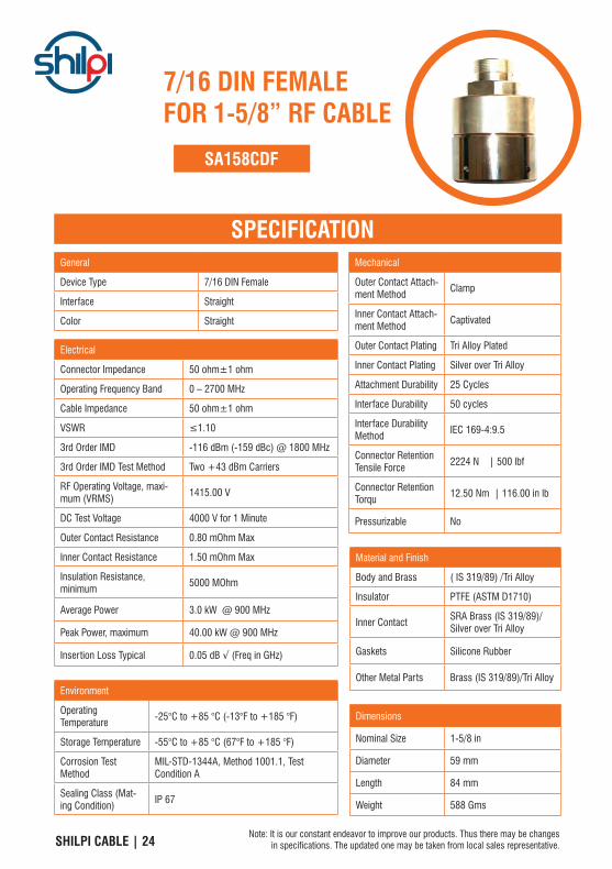
7/16 DIN FEMALE FOR 1-5/8” RF CABLE
SA158CDF
Electrical
Connector Impedance 50 ohm±1 ohm
Operating Frequency Band 0 – 2700 MHz
Cable Impedance 50 ohm±1 ohm
VSWR ≤1.10
3rd Order IMD -116 dBm (-159 dBc) @ 1800 MHz
3rd Order IMD Test Method Two +43 dBm Carriers
RF Operating Voltage, maxi-mum (VRMS)
1415.00 V
DC Test Voltage 4000 V for 1 Minute
Outer Contact Resistance 0.80 mOhm Max
Inner Contact Resistance 1.50 mOhm Max
Insulation Resistance, minimum
5000 MOhm
Average Power 3.0 kW @ 900 MHz
Peak Power, maximum 40.00 kW @ 900 MHz
Insertion Loss Typical 0.05 dB √ (Freq in GHz)
General
Device Type 7/16 DIN Female
thgiartSecafretnI
thgiartSroloC
Environment
Operating Temperature
-25°C to +85 °C (-13°F to +185 °F)
Storage Temperature -55°C to +85 °C (67°F to +185 °F)
Corrosion Test Method
MIL-STD-1344A, Method 1001.1, Test Condition A
Sealing Class (Mat-ing Condition)
IP 67
Dimensions
Nominal Size 1-5/8 in
Diameter 59 mm
Length 84 mm
Weight 588 Gms
Material and Finish
Body and Brass ( IS 319/89) /Tri Alloy
Insulator PTFE (ASTM D1710)
Inner ContactSRA Brass (IS 319/89)/ Silver over Tri Alloy
Gaskets Silicone Rubber
Other Metal Parts Brass (IS 319/89)/Tri Alloy
Mechanical
Outer Contact Attach-ment Method
Clamp
Inner Contact Attach-ment Method
Captivated
Outer Contact Plating Tri Alloy Plated
Inner Contact Plating Silver over Tri Alloy
Attachment Durability 25 Cycles
Interface Durability 50 cycles
Interface Durability Method
IEC 169-4:9.5
Connector Retention Tensile Force
2224 N | 500 lbf
Connector Retention Torqu
12.50 Nm | 116.00 in lb
Pressurizable No
SPECIFICATION
22
SA158CDF
7/16 DIN FEMALEFOR 1-5/8” RF CABLE
7/16 DIN FEMALE FOR 7/8” RF CABLE
SA078CDM
Electrical
Connector Impedance 50 ohm±1 ohm
Operating Frequency Band 0 – 3000 MHz
Cable Impedance 50 ohm±1 ohm
VSWR ≤1.10
3rd Order IMD -116 dBm (-159 dBc) @ 1800 MHz
3rd Order IMD Test Method Two +43 dBm Carriers
RF Operating Voltage, maxi-mum (VRMS)
1415.00 V
minimum 5000 MOhm
Average Power 1.0 kW @900 MHz
Peak Power, maximum 40.00 kW @ 900 MHz
Insertion Loss Typical 0.05 dB √ (Freq in GHz)
Environment
Operating Temperature -40°C to +85 °C (40°F to 185°F)
Storage Temperature -55°C to +85 °C (67°F to +185 °F)
Impact (Shock) 1 Km/sec
Corrosion Test MethodMIL-STD-1344A, Method 1001.1, Test Condition A
Sealing Class (Mated Condition)
IP 67
Dimensions
Nominal Size 7/8 in
Diameter 34.5mm
Length 48.5mm
Weight 146 gms
Material and Finish
Body Brass ( IS 319/89) /Tri Alloy
Insulator PTFE (ASTM D1710)
Inner ContactSRA Brass (IS 319/89)/ Silver over Tri Alloy
Gaskets Silicone Rubber
Other Metal Parts Brass (IS 319/89)/Tri Alloy
Mechanical
Outer Contact Attach-ment Method
Clamp
Inner Contact Attach-ment Method
Captivated
Outer Contact Plating Tri Alloy Plated
Inner Contact Plating Silver over Tri Alloy
Attachment Durability 250 Cycles
Interface Durability 500 cycles
Interface Durability Method
IEC 169-4:9.5
Connector Retention Tensile Force
1300 N
Connector Retention Torqu
9 N-m
Pressurizable No
SPECIFICATIONGeneral
NID 617ecafretnI Female Body
thgiartSelytS Mounting
thgiartSelgnA
DC Test Voltage 4000 V for 1 Minute
Outer Contact Resistance 0.2 m Ohm Max
Inner Contact Resistance 1.0 m Ohm Max
Insulation Resistance,
23 | SHILPI CABLE

25 | SHILPI CABLE Note: It is our constant endeavor to improve our products. Thus there may be changes in specifications. The updated one may be taken from local sales representative.SHILPI CABLE |
7/16 DIN FEMALE FOR 1-5/8” RF CABLE
SA158CDF
Electrical
Connector Impedance 50 ohm±1 ohm
Operating Frequency Band 0 – 2700 MHz
Cable Impedance 50 ohm±1 ohm
VSWR ≤1.10
3rd Order IMD -116 dBm (-159 dBc) @ 1800 MHz
3rd Order IMD Test Method Two +43 dBm Carriers
RF Operating Voltage, maxi-mum (VRMS)
1415.00 V
DC Test Voltage 4000 V for 1 Minute
Outer Contact Resistance 0.80 mOhm Max
Inner Contact Resistance 1.50 mOhm Max
Insulation Resistance, minimum
5000 MOhm
Average Power 3.0 kW @ 900 MHz
Peak Power, maximum 40.00 kW @ 900 MHz
Insertion Loss Typical 0.05 dB √ (Freq in GHz)
General
Device Type 7/16 DIN Female
thgiartSecafretnI
thgiartSroloC
Environment
Operating Temperature
-25°C to +85 °C (-13°F to +185 °F)
Storage Temperature -55°C to +85 °C (67°F to +185 °F)
Corrosion Test Method
MIL-STD-1344A, Method 1001.1, Test Condition A
Sealing Class (Mat-ing Condition)
IP 67
Dimensions
Nominal Size 1-5/8 in
Diameter 59 mm
Length 84 mm
Weight 588 Gms
Material and Finish
Body and Brass ( IS 319/89) /Tri Alloy
Insulator PTFE (ASTM D1710)
Inner ContactSRA Brass (IS 319/89)/ Silver over Tri Alloy
Gaskets Silicone Rubber
Other Metal Parts Brass (IS 319/89)/Tri Alloy
Mechanical
Outer Contact Attach-ment Method
Clamp
Inner Contact Attach-ment Method
Captivated
Outer Contact Plating Tri Alloy Plated
Inner Contact Plating Silver over Tri Alloy
Attachment Durability 25 Cycles
Interface Durability 50 cycles
Interface Durability Method
IEC 169-4:9.5
Connector Retention Tensile Force
2224 N | 500 lbf
Connector Retention Torqu
12.50 Nm | 116.00 in lb
Pressurizable No
SPECIFICATION
22
SA078CDM
7/16 DIN FEMALEFOR 7/8” RF CABLE7/16 DIN FEMALE FOR 7/8” RF CABLE
SA078CDM
Electrical
Connector Impedance 50 ohm±1 ohm
Operating Frequency Band 0 – 3000 MHz
Cable Impedance 50 ohm±1 ohm
VSWR ≤1.10
3rd Order IMD -116 dBm (-159 dBc) @ 1800 MHz
3rd Order IMD Test Method Two +43 dBm Carriers
RF Operating Voltage, maxi-mum (VRMS)
1415.00 V
minimum 5000 MOhm
Average Power 1.0 kW @900 MHz
Peak Power, maximum 40.00 kW @ 900 MHz
Insertion Loss Typical 0.05 dB √ (Freq in GHz)
Environment
Operating Temperature -40°C to +85 °C (40°F to 185°F)
Storage Temperature -55°C to +85 °C (67°F to +185 °F)
Impact (Shock) 1 Km/sec
Corrosion Test MethodMIL-STD-1344A, Method 1001.1, Test Condition A
Sealing Class (Mated Condition)
IP 67
Dimensions
Nominal Size 7/8 in
Diameter 34.5mm
Length 48.5mm
Weight 146 gms
Material and Finish
Body Brass ( IS 319/89) /Tri Alloy
Insulator PTFE (ASTM D1710)
Inner ContactSRA Brass (IS 319/89)/ Silver over Tri Alloy
Gaskets Silicone Rubber
Other Metal Parts Brass (IS 319/89)/Tri Alloy
Mechanical
Outer Contact Attach-ment Method
Clamp
Inner Contact Attach-ment Method
Captivated
Outer Contact Plating Tri Alloy Plated
Inner Contact Plating Silver over Tri Alloy
Attachment Durability 250 Cycles
Interface Durability 500 cycles
Interface Durability Method
IEC 169-4:9.5
Connector Retention Tensile Force
1300 N
Connector Retention Torqu
9 N-m
Pressurizable No
SPECIFICATIONGeneral
NID 617ecafretnI Female Body
thgiartSelytS Mounting
thgiartSelgnA
DC Test Voltage 4000 V for 1 Minute
Outer Contact Resistance 0.2 m Ohm Max
Inner Contact Resistance 1.0 m Ohm Max
Insulation Resistance,
23 | SHILPI CABLE
SHILPI CABLE | 26Note: It is our constant endeavor to improve our products. Thus there may be changes
in specifications. The updated one may be taken from local sales representative.SHILPI CABLE |
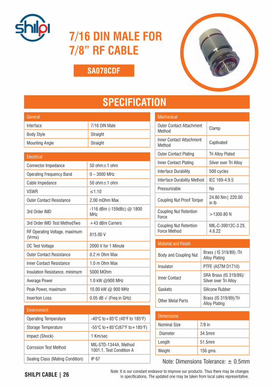
7/16 DIN MALE FOR 7/8” RF CABLE
SA078CDF
Electrical
Connector Impedance 50 ohm±1 ohm
Operating Frequency Band 0 – 3000 MHz
Cable Impedance 50 ohm±1 ohm
VSWR ≤1.10
Outer Contact Resistance 2.00 mOhm Max
3rd Order IMD-116 dBm (-159dBc) @ 1800 MHz
3rd Order IMD Test MethodTwo +43 dBm Carriers
RF Operating Voltage, maximum (Vrms)
815.00 V
DC Test Voltage 2000 V for 1 Minute
Outer Contact Resistance 0.2 m Ohm Max
Inner Contact Resistance 1.0 m Ohm Max
Insulation Resistance, minimum 5000 MOhm
Average Power 1.0 kW @900 MHz
Peak Power, maximum 10.00 kW @ 900 MHz
Insertion Loss 0.05 dB √ (Freq in GHz)
Environment
Operating Temperature -40°C to+85°C (40°F to 185°F)
Storage Temperature -55°C to+85°C(67°F to+185°F)
Impact (Shock) 1 Km/sec
Corrosion Test MethodMIL-STD-1344A, Method 1001.1, Test Condition A
Sealing Class (Mating Condition) IP 67
Dimensions
Nominal Size 7/8 in
Diameter 34.5mm
Length 51.5mm
Weight 156 gms
Material and Finish
Body and Coupling NutBrass ( IS 319/89) /Tri Alloy Plating
Insulator PTFE (ASTM D1710)
Inner ContactSRA Brass (IS 319/89)/ Silver over Tri Alloy
Gaskets Silicone Rubber
Other Metal PartsBrass (IS 319/89)/Tri Alloy Plating
Mechanical
Outer Contact Attachment Method
Clamp
Inner Contact Attachment Method
Captivated
Outer Contact Plating Tri Alloy Plated
Inner Contact Plating Silver over Tri Alloy
Interface Durability 500 cycles
Interface Durability Method IEC 169-4:9.5
Pressurizable No
Coupling Nut Proof Torque24.80 Nm| 220.00 in lb
Coupling Nut Retention Force
>1300.80 N
Coupling Nut Retention Force Method
MIL-C-39012C-3.25, 4.6.22
SPECIFICATIONGeneral
NID 61/7ecafretnI Male
Body Style Straight
Mounting Angle Straight
Note: Dimensions Tolerance: ± 0.5mm
24
SA078CDF
7/16 DIN MALE FOR7/8” RF CABLE
SHILPI CABLE |
7/16 DIN MALE FOR 7/8” RF CABLE
SA078CDF
Electrical
Connector Impedance 50 ohm±1 ohm
Operating Frequency Band 0 – 3000 MHz
Cable Impedance 50 ohm±1 ohm
VSWR ≤1.10
Outer Contact Resistance 2.00 mOhm Max
3rd Order IMD-116 dBm (-159dBc) @ 1800 MHz
3rd Order IMD Test MethodTwo +43 dBm Carriers
RF Operating Voltage, maximum (Vrms)
815.00 V
DC Test Voltage 2000 V for 1 Minute
Outer Contact Resistance 0.2 m Ohm Max
Inner Contact Resistance 1.0 m Ohm Max
Insulation Resistance, minimum 5000 MOhm
Average Power 1.0 kW @900 MHz
Peak Power, maximum 10.00 kW @ 900 MHz
Insertion Loss 0.05 dB √ (Freq in GHz)
Environment
Operating Temperature -40°C to+85°C (40°F to 185°F)
Storage Temperature -55°C to+85°C(67°F to+185°F)
Impact (Shock) 1 Km/sec
Corrosion Test MethodMIL-STD-1344A, Method 1001.1, Test Condition A
Sealing Class (Mating Condition) IP 67
Dimensions
Nominal Size 7/8 in
Diameter 34.5mm
Length 51.5mm
Weight 156 gms
Material and Finish
Body and Coupling NutBrass ( IS 319/89) /Tri Alloy Plating
Insulator PTFE (ASTM D1710)
Inner ContactSRA Brass (IS 319/89)/ Silver over Tri Alloy
Gaskets Silicone Rubber
Other Metal PartsBrass (IS 319/89)/Tri Alloy Plating
Mechanical
Outer Contact Attachment Method
Clamp
Inner Contact Attachment Method
Captivated
Outer Contact Plating Tri Alloy Plated
Inner Contact Plating Silver over Tri Alloy
Interface Durability 500 cycles
Interface Durability Method IEC 169-4:9.5
Pressurizable No
Coupling Nut Proof Torque24.80 Nm| 220.00 in lb
Coupling Nut Retention Force
>1300.80 N
Coupling Nut Retention Force Method
MIL-C-39012C-3.25, 4.6.22
SPECIFICATIONGeneral
NID 61/7ecafretnI Male
Body Style Straight
Mounting Angle Straight
Note: Dimensions Tolerance: ± 0.5mm
24
DIN FEMALE- N MALE ADAPTER
SARADFNM
Electrical
Connector Impedance 50 ohm±1 ohm
Operating Frequency Band 0 – 3000 MHz
mho 1±mho 05ecnadepmI elbaC
VSWR ≤1.12
Outer Contact Resistance 2.00 mOhm Max
Inner Contact Resistance 0.3 m Ohm Max
Insulation Resistance, minimum 5000 MOhm
zHM 009 @ Wk 6.0rewoP egarevA
Peak Power, maximum 10.00 kW @900 MHz
Insertion Loss Typical 0.05 dB √ (Freq in GHz)
General
elameF NID 61/7epyT eciveD
elaM NecafretnI
thgiartSroloC
Environment
Operating Temperature -55°C to +85 °C (-67°F to +185 °F)
Storage Temperature -55°C to +85 °C (-67°F to +185 °F)
Corrosion Test MethodMILSTD1344A, Method 1001.1, Test Condition A
Sealing Class (Mating Condition)
IP 67
Dimensions
Diameter 29.80 mm
Length 48.00 mm
Weight 108.00 g
Material and Finish
BodyBrass ( IS 319/89) /Tri Alloy
Insulator PTFE (ASTM D1710)
Inner ContactSRA Brass (IS 319/89)/ Silver over Tri Alloy
Gaskets Silicone Rubber
Other Metal PartsBrass (IS 319/89)/Tri Alloy Plating
Mechanical
Outer Contact Plating Tri Alloy Plated
Inner Contact Plating Silver over Tri Alloy
Attachment Durability 25 cycles
Interface Durability 500 cycles
SPECIFICATION
25 | SHILPI CABLE

27 | SHILPI CABLE Note: It is our constant endeavor to improve our products. Thus there may be changes in specifications. The updated one may be taken from local sales representative.
SARADFNM
DIN FEMALE - NMALE ADAPTER
SHILPI CABLE |
7/16 DIN MALE FOR 7/8” RF CABLE
SA078CDF
Electrical
Connector Impedance 50 ohm±1 ohm
Operating Frequency Band 0 – 3000 MHz
Cable Impedance 50 ohm±1 ohm
VSWR ≤1.10
Outer Contact Resistance 2.00 mOhm Max
3rd Order IMD-116 dBm (-159dBc) @ 1800 MHz
3rd Order IMD Test MethodTwo +43 dBm Carriers
RF Operating Voltage, maximum (Vrms)
815.00 V
DC Test Voltage 2000 V for 1 Minute
Outer Contact Resistance 0.2 m Ohm Max
Inner Contact Resistance 1.0 m Ohm Max
Insulation Resistance, minimum 5000 MOhm
Average Power 1.0 kW @900 MHz
Peak Power, maximum 10.00 kW @ 900 MHz
Insertion Loss 0.05 dB √ (Freq in GHz)
Environment
Operating Temperature -40°C to+85°C (40°F to 185°F)
Storage Temperature -55°C to+85°C(67°F to+185°F)
Impact (Shock) 1 Km/sec
Corrosion Test MethodMIL-STD-1344A, Method 1001.1, Test Condition A
Sealing Class (Mating Condition) IP 67
Dimensions
Nominal Size 7/8 in
Diameter 34.5mm
Length 51.5mm
Weight 156 gms
Material and Finish
Body and Coupling NutBrass ( IS 319/89) /Tri Alloy Plating
Insulator PTFE (ASTM D1710)
Inner ContactSRA Brass (IS 319/89)/ Silver over Tri Alloy
Gaskets Silicone Rubber
Other Metal PartsBrass (IS 319/89)/Tri Alloy Plating
Mechanical
Outer Contact Attachment Method
Clamp
Inner Contact Attachment Method
Captivated
Outer Contact Plating Tri Alloy Plated
Inner Contact Plating Silver over Tri Alloy
Interface Durability 500 cycles
Interface Durability Method IEC 169-4:9.5
Pressurizable No
Coupling Nut Proof Torque24.80 Nm| 220.00 in lb
Coupling Nut Retention Force
>1300.80 N
Coupling Nut Retention Force Method
MIL-C-39012C-3.25, 4.6.22
SPECIFICATIONGeneral
NID 61/7ecafretnI Male
Body Style Straight
Mounting Angle Straight
Note: Dimensions Tolerance: ± 0.5mm
24
DIN FEMALE- N MALE ADAPTER
SARADFNM
Electrical
Connector Impedance 50 ohm±1 ohm
Operating Frequency Band 0 – 3000 MHz
mho 1±mho 05ecnadepmI elbaC
VSWR ≤1.12
Outer Contact Resistance 2.00 mOhm Max
Inner Contact Resistance 0.3 m Ohm Max
Insulation Resistance, minimum 5000 MOhm
zHM 009 @ Wk 6.0rewoP egarevA
Peak Power, maximum 10.00 kW @900 MHz
Insertion Loss Typical 0.05 dB √ (Freq in GHz)
General
elameF NID 61/7epyT eciveD
elaM NecafretnI
thgiartSroloC
Environment
Operating Temperature -55°C to +85 °C (-67°F to +185 °F)
Storage Temperature -55°C to +85 °C (-67°F to +185 °F)
Corrosion Test MethodMILSTD1344A, Method 1001.1, Test Condition A
Sealing Class (Mating Condition)
IP 67
Dimensions
Diameter 29.80 mm
Length 48.00 mm
Weight 108.00 g
Material and Finish
BodyBrass ( IS 319/89) /Tri Alloy
Insulator PTFE (ASTM D1710)
Inner ContactSRA Brass (IS 319/89)/ Silver over Tri Alloy
Gaskets Silicone Rubber
Other Metal PartsBrass (IS 319/89)/Tri Alloy Plating
Mechanical
Outer Contact Plating Tri Alloy Plated
Inner Contact Plating Silver over Tri Alloy
Attachment Durability 25 cycles
Interface Durability 500 cycles
SPECIFICATION
25 | SHILPI CABLE
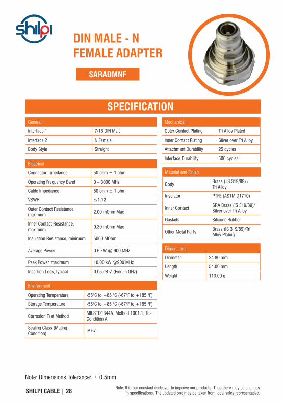
SHILPI CABLE | 28Note: It is our constant endeavor to improve our products. Thus there may be changes
in specifications. The updated one may be taken from local sales representative.
7/16 DIN MALE FOR ½” SF CABLE
Note: Dimensions Tolerance: ± 0.5mm
SA12SCDM
Electrical
Connector Impedance 50 ohm ± 1 ohm
Operating Frequency Band 0 – 3000 MHz
Cable Impedance 50 ohm ± 1 ohm
VSWR ≤1.10
3rd Order IMD-110 dBm (-153 dBc) @
General
elameF NID 61/7 ecafretnI
Body Style Straight
Mounting Angle Straight
Environment
Operating Temperature -40°C to+85°C(-40°F to+185°F)
Storage Temperature -55°C to+85°C(-67°F to+185°F)
Corrosion Test MethodMILSTD1344A, Method 1001.1, Test Condition A
Sealing Class (Mating Condition)
IP 67
Dimensions
Nominal Size 1/2 in Superflex
Diameter 24.70 mm
Length 55.60 mm
Weight 63.20 g
Material and Finish
Body Brass ( IS 319/89) /Tri Alloy
Insulator PTFE (ASTM D1710)
Inner Contact SRA Brass (IS 319/89)/ Silver over Tri Alloy
Gaskets Silicone Rubber
Other Metal Parts Brass (IS 319/89)/Tri Alloy Plating
Mechanical
Outer Contact Attachment Method
Clamp
Inner Contact Attachment Method
Captivated
Outer Contact Plating Tri-Alloy Plating
Inner Contact Plating Silver over Tri Alloy
Attachment Durability 25 cycles
Interface Durability 500 cycles
Interface Durability Method IEC 169-4:9.5
Connector Retention Tensile Force
1110 N | 250 lbf
Pressurizable No
Coupling Nut Proof Torque25.00 Nm | 221.27 in lb
Coupling Nut Retention Force
1000.00 N | 224.81 lbf
Coupling Nut Retention Force Method
MIL-C-39012C-3.25, 4.6.22
Connector Retention torque 6 Nm
SPECIFICATION
1800 MHz 3rd Order
IMD Test Method Two +43 dBm Carriers
RF Operating Voltage, maximum (Vrms) 1415 V
V 0002egatloV tseT CD
Outer Contact Resistance, maximum 1.5 mOhm Max
Inner Contact Resistance, maximum 0.8 mOhm Max
Insulation Resistance, minimum 5000 MOhm
zHM 009 @ Wk 0.1rewoP egarevA
Peak Power, maximum 10.00 kW @900 MHz
Insertion Loss, typical 0.05 dB √ (Freq in GHz)
SHILPI CABLE |
SARADMNF
DIN MALE - NFEMALE ADAPTER
SHILPI CABLE |
DIN MALE- N FEMALE ADAPTER
SARADMNF
Electrical
Connector Impedance 50 ohm ± 1 ohm
Operating Frequency Band 0 – 3000 MHz
Cable Impedance 50 ohm ± 1 ohm
VSWR ≤1.12
Outer Contact Resistance, maximum
2.00 mOhm Max
Inner Contact Resistance, maximum
0.30 mOhm Max
Insulation Resistance, minimum 5000 MOhm
Average Power 0.6 kW @ 900 MHz
Peak Power, maximum 10.00 kW @900 MHz
Insertion Loss, typical 0.05 dB √ (Freq in GHz)
General
elaM NID 61/71 ecafretnI
Interface 2 N Female
Body Style Straight
Environment
Operating Temperature -55°C to +85 °C (-67°F to +185 °F)
Storage Temperature -55°C to +85 °C (-67°F to +185 °F)
Corrosion Test Method MILSTD1344A, Method 1001.1, Test Condition A
Sealing Class (Mating Condition)
IP 67
Dimensions
Diameter 24.80 mm
Length 54.00 mm
Weight 113.00 g
Material and Finish
BodyBrass ( IS 319/89) /Tri Alloy
Insulator PTFE (ASTM D1710)
Inner ContactSRA Brass (IS 319/89)/ Silver over Tri Alloy
Gaskets Silicone Rubber
Other Metal PartsBrass (IS 319/89)/Tri Alloy Plating
Mechanical
Outer Contact Plating Tri Alloy Plated
Inner Contact Plating Silver over Tri Alloy
Attachment Durability 25 cycles
Interface Durability 500 cycles
SPECIFICATION
Note: Dimensions Tolerance: ± 0.5mm
26
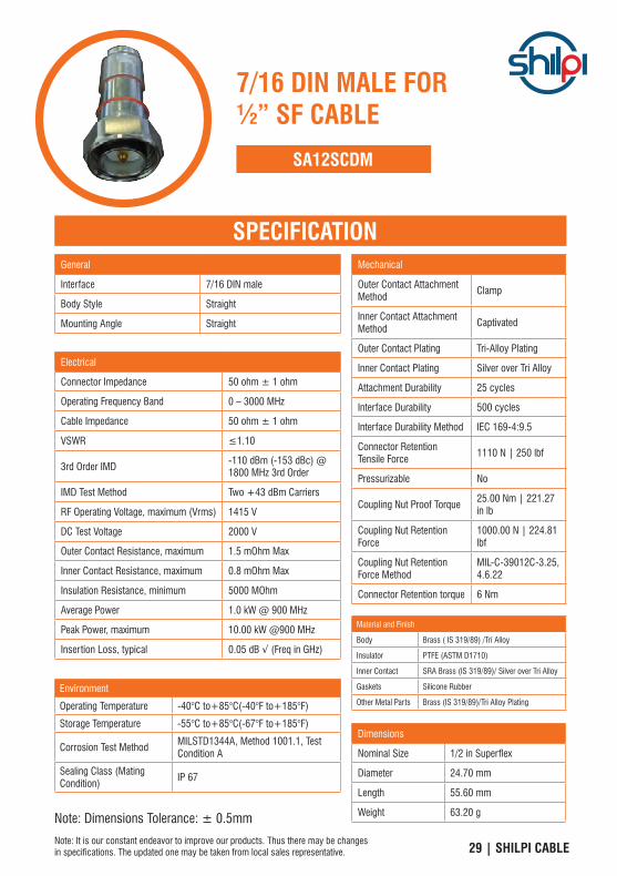
29 | SHILPI CABLE Note: It is our constant endeavor to improve our products. Thus there may be changes in specifications. The updated one may be taken from local sales representative.
7/16 DIN MALE FOR ½” SF CABLE
SA12SCDM
7/16 DIN MALE FOR ½” SF CABLE
Note: Dimensions Tolerance: ± 0.5mm
SA12SCDM
Electrical
Connector Impedance 50 ohm ± 1 ohm
Operating Frequency Band 0 – 3000 MHz
Cable Impedance 50 ohm ± 1 ohm
VSWR ≤1.10
3rd Order IMD-110 dBm (-153 dBc) @
General
elameF NID 61/7 ecafretnI
Body Style Straight
Mounting Angle Straight
Environment
Operating Temperature -40°C to+85°C(-40°F to+185°F)
Storage Temperature -55°C to+85°C(-67°F to+185°F)
Corrosion Test MethodMILSTD1344A, Method 1001.1, Test Condition A
Sealing Class (Mating Condition)
IP 67
Dimensions
Nominal Size 1/2 in Superflex
Diameter 24.70 mm
Length 55.60 mm
Weight 63.20 g
Material and Finish
Body Brass ( IS 319/89) /Tri Alloy
Insulator PTFE (ASTM D1710)
Inner Contact SRA Brass (IS 319/89)/ Silver over Tri Alloy
Gaskets Silicone Rubber
Other Metal Parts Brass (IS 319/89)/Tri Alloy Plating
Mechanical
Outer Contact Attachment Method
Clamp
Inner Contact Attachment Method
Captivated
Outer Contact Plating Tri-Alloy Plating
Inner Contact Plating Silver over Tri Alloy
Attachment Durability 25 cycles
Interface Durability 500 cycles
Interface Durability Method IEC 169-4:9.5
Connector Retention Tensile Force
1110 N | 250 lbf
Pressurizable No
Coupling Nut Proof Torque25.00 Nm | 221.27 in lb
Coupling Nut Retention Force
1000.00 N | 224.81 lbf
Coupling Nut Retention Force Method
MIL-C-39012C-3.25, 4.6.22
Connector Retention torque 6 Nm
SPECIFICATION
1800 MHz 3rd Order
IMD Test Method Two +43 dBm Carriers
RF Operating Voltage, maximum (Vrms) 1415 V
V 0002egatloV tseT CD
Outer Contact Resistance, maximum 1.5 mOhm Max
Inner Contact Resistance, maximum 0.8 mOhm Max
Insulation Resistance, minimum 5000 MOhm
zHM 009 @ Wk 0.1rewoP egarevA
Peak Power, maximum 10.00 kW @900 MHz
Insertion Loss, typical 0.05 dB √ (Freq in GHz)
SHILPI CABLE |
male
SHILPI CABLE |
DIN MALE- N FEMALE ADAPTER
SARADMNF
Electrical
Connector Impedance 50 ohm ± 1 ohm
Operating Frequency Band 0 – 3000 MHz
Cable Impedance 50 ohm ± 1 ohm
VSWR ≤1.12
Outer Contact Resistance, maximum
2.00 mOhm Max
Inner Contact Resistance, maximum
0.30 mOhm Max
Insulation Resistance, minimum 5000 MOhm
Average Power 0.6 kW @ 900 MHz
Peak Power, maximum 10.00 kW @900 MHz
Insertion Loss, typical 0.05 dB √ (Freq in GHz)
General
elaM NID 61/71 ecafretnI
Interface 2 N Female
Body Style Straight
Environment
Operating Temperature -55°C to +85 °C (-67°F to +185 °F)
Storage Temperature -55°C to +85 °C (-67°F to +185 °F)
Corrosion Test Method MILSTD1344A, Method 1001.1, Test Condition A
Sealing Class (Mating Condition)
IP 67
Dimensions
Diameter 24.80 mm
Length 54.00 mm
Weight 113.00 g
Material and Finish
BodyBrass ( IS 319/89) /Tri Alloy
Insulator PTFE (ASTM D1710)
Inner ContactSRA Brass (IS 319/89)/ Silver over Tri Alloy
Gaskets Silicone Rubber
Other Metal PartsBrass (IS 319/89)/Tri Alloy Plating
Mechanical
Outer Contact Plating Tri Alloy Plated
Inner Contact Plating Silver over Tri Alloy
Attachment Durability 25 cycles
Interface Durability 500 cycles
SPECIFICATION
Note: Dimensions Tolerance: ± 0.5mm
26

SHILPI CABLE | 30Note: It is our constant endeavor to improve our products. Thus there may be changes
in specifications. The updated one may be taken from local sales representative.
7/16 DIN MALE FOR ½” FLEX CABLE
SA012CDM
7/16 DIN MALE FOR ½” FLEX CABLE
SA012CDM
SPECIFICATION
Outer Contact Resistance, maximum
Inner Contact Resistance, maximum
General
elaM niD 61/7 ecafretnI
Body Style Straight
Mounting Angle Straight
Environment
Operating Temperature -40°C to +85 °C (-40°F to +185 °F)
Storage Temperature -55°C to +85 °C (-67°F to +185 °F)
Corrosion Test MethodMILSTD1344A, Method 1001.1, Test Condition A
Sealing Class (Mating Condition)
IP 67Dimensions
Nominal Size 1/2 in Flex Length 55.60 mm
Diameter 24.70 mm Weight 63.20 g
Material and Finish
Body Brass (IS 319/89) /Tri Alloy
Insulator PTFE (ASTM D1710)
Inner ContactSRA Brass (IS 319/89)/ Silver over Tri Alloy
Gaskets Silicone Rubber
Other Metal Parts Brass (IS 319/89)/Tri Alloy
Mechanical
Outer Contact Attachment Method
Clamp
Inner Contact Attachment Method
Captivated
Outer Contact Plating Tri-Alloy Plating
Inner Contact Plating Silver over Tri Alloy
Attachment Durability 25 cycles
Interface Durability 500 cycles
Interface Durability Method IEC 169-4:9.5
Connector Retention Tensile Force
1110 N | 250 lbf
Pressurizable No
Coupling Nut Proof Torque25.00 Nm | 221.27 in lb
Coupling Nut Retention Force
500.00 N | 224.81 lbf
Coupling Nut Retention Force Method
MIL-C-39012C-3.25, 4.6.22
Electrical
Connector Impedance 50 ohm ± 1 ohm
Operating Frequency Band 0 – 3000 MHz
Cable Impedance 50 ohm ± 1 ohm
VSWR ≤1.10
3rd Order IMD -110 dBm(-153 dBc)@1800 MHz
3rd Order IMD Test Method Two +43 dBm Carriers
RF Operating Voltage, maxi-mum (Vrms) 815 V
DC Test Voltage 4000 V
2.0 m Ohm Max
0.3 m Ohm Max
Insulation Resistance, minimum 5000 M Ohm
Average Power 1.0 kW @ 900 MHz
Peak Power, maximum 10.00 kW @ 900 MHz
Insertion Loss, typical 0.05 dB √ (Freq in GHz)
Connector Retention torque 6 Nm
Note: Dimensions Tolerance: ± 0.5mm
SHILPI CABLE | 8
31 | SHILPI CABLE
7/16 DIN MALE FOR ½” FLEX CABLE
SA012CDM
SPECIFICATION
Outer Contact Resistance, maximum
Inner Contact Resistance, maximum
General
elaM niD 61/7 ecafretnI
Body Style Straight
Mounting Angle Straight
Environment
Operating Temperature -40°C to +85 °C (-40°F to +185 °F)
Storage Temperature -55°C to +85 °C (-67°F to +185 °F)
Corrosion Test MethodMILSTD1344A, Method 1001.1, Test Condition A
Sealing Class (Mating Condition)
IP 67Dimensions
Nominal Size 1/2 in Flex Length 55.60 mm
Diameter 24.70 mm Weight 63.20 g
Material and Finish
Body Brass (IS 319/89) /Tri Alloy
Insulator PTFE (ASTM D1710)
Inner ContactSRA Brass (IS 319/89)/ Silver over Tri Alloy
Gaskets Silicone Rubber
Other Metal Parts Brass (IS 319/89)/Tri Alloy
Mechanical
Outer Contact Attachment Method
Clamp
Inner Contact Attachment Method
Captivated
Outer Contact Plating Tri-Alloy Plating
Inner Contact Plating Silver over Tri Alloy
Attachment Durability 25 cycles
Interface Durability 500 cycles
Interface Durability Method IEC 169-4:9.5
Connector Retention Tensile Force
1110 N | 250 lbf
Pressurizable No
Coupling Nut Proof Torque25.00 Nm | 221.27 in lb
Coupling Nut Retention Force
500.00 N | 224.81 lbf
Coupling Nut Retention Force Method
MIL-C-39012C-3.25, 4.6.22
Electrical
Connector Impedance 50 ohm ± 1 ohm
Operating Frequency Band 0 – 3000 MHz
Cable Impedance 50 ohm ± 1 ohm
VSWR ≤1.10
3rd Order IMD -110 dBm(-153 dBc)@1800 MHz
3rd Order IMD Test Method Two +43 dBm Carriers
RF Operating Voltage, maxi-mum (Vrms) 815 V
DC Test Voltage 4000 V
2.0 m Ohm Max
0.3 m Ohm Max
Insulation Resistance, minimum 5000 M Ohm
Average Power 1.0 kW @ 900 MHz
Peak Power, maximum 10.00 kW @ 900 MHz
Insertion Loss, typical 0.05 dB √ (Freq in GHz)
Connector Retention torque 6 Nm
Note: Dimensions Tolerance: ± 0.5mm
SHILPI CABLE | 8

SHILPI CABLE | 32Note: It is our constant endeavor to improve our products. Thus there may be changes
in specifications. The updated one may be taken from local sales representative.SHILPI CABLE | 32

33 | SHILPI CABLE Note: It is our constant endeavor to improve our products. Thus there may be changes in specifications. The updated one may be taken from local sales representative.
RF JUMPER
33 | SHILPI CABLE
CoaxialcableassembliesdeliversuperiorPIMperformancebecausethey’remanufacturedand tested to meet and exceed the toughest standards. We start by using select components —whicharethenfusedin-housetopremiumcables—tocreateanintegratedassemblywithphysicalandelectricalintegritythatnofield-fittedassemblycanmatch.Weofferscableassemblies in a wide variety of sizes and lengths to accommodate every need, including for outdoors,fire-ratedandplenumapplications.Wecanevenprovidecustomizedassembliesforin-building,in-cabinet,antennatransmitterandanyotherjumperapplication. Completely weatherproof Superiorqualityconstruction

SHILPI CABLE | 34Note: It is our constant endeavor to improve our products. Thus there may be changes
in specifications. The updated one may be taken from local sales representative.SHILPI CABLE |
JUMPER CABLE
SAI12JNMM
Electrical
Frequency Range DC-3 GHz
Characteristic Impedance 50±1 Ω
3rd Order IMD ≤117 dBm(-160dBc) @1800 MHz
3rd Order IMD Test Method Two +43 dBm Carriers
Return LossDC-1 GHz: ≥ 26 dB up to 3 GHz: ≥21.6dB
Attenuation (Max at 20 C)(Include Connectors + Cable up to length of 1m)
900 MHz 0.21 dB/mtr
1800 MHz 0.26 dB/mtr
2200 MHz 0.29 dB/mtr
3000 MHz 0.32 dB/mtr
Insulation Resistance >10000 MΩ
Contact Resistance of the connector
<0.4mΩ for the centre contact
<1.5mΩ for the outer contact
General
Body Style, Connector A N (M) Straight
Body Style, Connector B N (M) Straight
Cable Family 1/2in Super Flex Cables
rtM 1 htgneL
Attachment
Specially developed connectors using soldering technology that guarantees superior electrical characteristics
Environment Data
Operating Temperature Range -10 C to + 70 C
Storage Temperature Range -20 C to + 80 C
Mechanical
Reliability of ContactMinimum 500 mating
Cable Retention Force (Before degrading Electrical Specification)
Maximum 250 N
Coupling Nut TorqueMinimum 40-60 N metres (Manual)
Bending Radius (Repeated Bending)
Minimum 50mm
Bending Radius (Single Bending)
Minimum 32mm
Material Data
Cable
Inner Conductor Copper Clad Aluminum
Dielectric Foamed Polyethylene
Outer ConductorCorrugated Copper Tubing with Black Polyethylene Jacket
Connector
Body Brass (ASTM B 16) / Tri Alloy
InsulatorPTFE (ASTM D1457, Type 1. Grade 1)
Centre ContactStress Relived Brass –Tri Alloy Silver Plated
Outer Contact Brass-Tri Alloy Plated
Gasket Silicone Rubber
SPECIFICATION
1 mtr with N (M) Connector at each end
32
JUMPER CABLE 1 mtr with N (M) Connectorat each end
SAI12JNMM
EnvironmentData
OperatingTemperatureRange -10˚Cto+70˚C
StorageTemperatureRange -20˚Cto+80˚C
Attenuation(Maxat20˚C)
SHILPI CABLE |
JUMPER CABLE 5 MTR WITH DIN (M) CONNECTOR & N (M) CONNECTOR AT EACH END
Note: Dimensions Tolerance: ± 0.5mm
S12JDMNM
Electrical
Frequency Range DC-3 GHz
Characteristic Impedance 50Ω
VSWR 1.20 Max @ 3GHz
3rd Order IMD ≤117 dBm(-160dBc) @1800 MHz
3rd Order IMD Test Method Two +43 dBm Carriers
Return LossDC-1 GHz: ≥ 26 dB up to 2.2 GHz: ≥22 dB Up to 3 GHz ≥20.8 dB
Attenuation (Max at 20�C)(Include Connectors + Cable up to length of 5 m)
900 MHz 0.61 dB/mtr
1800 MHz 0.83 dB/mtr
2200 MHz 0.92 dB/mtr
3000 MHz 1.07 dB/mtr
Insulation Resistance >10000 MΩ
Contact Resistance of the connector
<0.4mΩ for the centre contact<1.5mΩ for the outer contact
General
Body Style, Connector A DIN (M) Straight
Body Style, Connector B N (M) Straight
Cable Family 1/2in Super Flex Cables
Length 5 Mtr
AttachmentSpecially developed connectors using soldering technology that guarantees superior electrical characteristics
Environment
Operating Temperature -10�C to + 70�C
Storage Temperature -20�C to + 80�C
Material
Cable
Inner Conductor Copper Clad Aluminum
Dielectric Foamed Polyethylene
Outer ConductorCorrugated Copper Tubing with Black Polyethylene Jacket
Connector
Body Brass (ASTM B 16) / Tri Alloy
InsulatorPTFE (ASTM D1457, Type 1. Grade 1)
Centre ContactStress Relived Brass –Tri Alloy Silver Plated
Outer Contact Brass-Tri Alloy Plated
Gasket Silicone Rubber
Mechanical
Reliability of ContactMinimum 500 mating
Cable Retention Force (Before degrading Electrical Specification)
Maximum 250 N
Coupling Nut TorqueMinimum 40-60 N metres (Manual)
Bending Radius (Repeated Bending)
Minimum 50mm
Bending Radius (Single Bending)
Minimum 32mm
SPECIFICATION
33
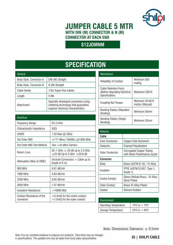
35 | SHILPI CABLE Note: It is our constant endeavor to improve our products. Thus there may be changes in specifications. The updated one may be taken from local sales representative.SHILPI CABLE |
JUMPER CABLE
SAI12JNMM
Electrical
Frequency Range DC-3 GHz
Characteristic Impedance 50±1 Ω
3rd Order IMD ≤117 dBm(-160dBc) @1800 MHz
3rd Order IMD Test Method Two +43 dBm Carriers
Return LossDC-1 GHz: ≥ 26 dB up to 3 GHz: ≥21.6dB
Attenuation (Max at 20 C)(Include Connectors + Cable up to length of 1m)
900 MHz 0.21 dB/mtr
1800 MHz 0.26 dB/mtr
2200 MHz 0.29 dB/mtr
3000 MHz 0.32 dB/mtr
Insulation Resistance >10000 MΩ
Contact Resistance of the connector
<0.4mΩ for the centre contact
<1.5mΩ for the outer contact
General
Body Style, Connector A N (M) Straight
Body Style, Connector B N (M) Straight
Cable Family 1/2in Super Flex Cables
rtM 1 htgneL
Attachment
Specially developed connectors using soldering technology that guarantees superior electrical characteristics
Environment Data
Operating Temperature Range -10 C to + 70 C
Storage Temperature Range -20 C to + 80 C
Mechanical
Reliability of ContactMinimum 500 mating
Cable Retention Force (Before degrading Electrical Specification)
Maximum 250 N
Coupling Nut TorqueMinimum 40-60 N metres (Manual)
Bending Radius (Repeated Bending)
Minimum 50mm
Bending Radius (Single Bending)
Minimum 32mm
Material Data
Cable
Inner Conductor Copper Clad Aluminum
Dielectric Foamed Polyethylene
Outer ConductorCorrugated Copper Tubing with Black Polyethylene Jacket
Connector
Body Brass (ASTM B 16) / Tri Alloy
InsulatorPTFE (ASTM D1457, Type 1. Grade 1)
Centre ContactStress Relived Brass –Tri Alloy Silver Plated
Outer Contact Brass-Tri Alloy Plated
Gasket Silicone Rubber
SPECIFICATION
1 mtr with N (M) Connector at each end
32
JUMPER CABLE 5 MTR WITH DIN (M) CONNECTOR & N (M) CONNECTOR AT EACH END
S12JDMNM
SHILPI CABLE |
JUMPER CABLE 5 MTR WITH DIN (M) CONNECTOR & N (M) CONNECTOR AT EACH END
Note: Dimensions Tolerance: ± 0.5mm
S12JDMNM
Electrical
Frequency Range DC-3 GHz
Characteristic Impedance 50Ω
VSWR 1.20 Max @ 3GHz
3rd Order IMD ≤117 dBm(-160dBc) @1800 MHz
3rd Order IMD Test Method Two +43 dBm Carriers
Return LossDC-1 GHz: ≥ 26 dB up to 2.2 GHz: ≥22 dB Up to 3 GHz ≥20.8 dB
Attenuation (Max at 20�C)(Include Connectors + Cable up to length of 5 m)
900 MHz 0.61 dB/mtr
1800 MHz 0.83 dB/mtr
2200 MHz 0.92 dB/mtr
3000 MHz 1.07 dB/mtr
Insulation Resistance >10000 MΩ
Contact Resistance of the connector
<0.4mΩ for the centre contact<1.5mΩ for the outer contact
General
Body Style, Connector A DIN (M) Straight
Body Style, Connector B N (M) Straight
Cable Family 1/2in Super Flex Cables
Length 5 Mtr
AttachmentSpecially developed connectors using soldering technology that guarantees superior electrical characteristics
Environment
Operating Temperature -10�C to + 70�C
Storage Temperature -20�C to + 80�C
Material
Cable
Inner Conductor Copper Clad Aluminum
Dielectric Foamed Polyethylene
Outer ConductorCorrugated Copper Tubing with Black Polyethylene Jacket
Connector
Body Brass (ASTM B 16) / Tri Alloy
InsulatorPTFE (ASTM D1457, Type 1. Grade 1)
Centre ContactStress Relived Brass –Tri Alloy Silver Plated
Outer Contact Brass-Tri Alloy Plated
Gasket Silicone Rubber
Mechanical
Reliability of ContactMinimum 500 mating
Cable Retention Force (Before degrading Electrical Specification)
Maximum 250 N
Coupling Nut TorqueMinimum 40-60 N metres (Manual)
Bending Radius (Repeated Bending)
Minimum 50mm
Bending Radius (Single Bending)
Minimum 32mm
SPECIFICATION
33
-100Cto+700C
-200Cto+800C

SHILPI CABLE | 36Note: It is our constant endeavor to improve our products. Thus there may be changes
in specifications. The updated one may be taken from local sales representative.SHILPI CABLE | 36SHILPI CABLE | 36
37 | SHILPI CABLE Note: It is our constant endeavor to improve our products. Thus there may be changes in specifications. The updated one may be taken from local sales representative. 37 | SHILPI CABLE 37 | SHILPI CABLE
SPLITTERPassivedevicesthatpowermanyoftheworld’smostefficientwirelessnetworks.Bydeliver-ingperformanceandlongevity,ourpassivedeviceshelpoperatorsoptimizetheirOpExwhilemaximizing their network efficiency.
Oursplitters,couplers,tappersandterminationaremanufacturedtothehigheststandardstoensure that active components in the network function properly. Enable antennas to transmit and receive signals accurately, year after year Offerruggeddurabilitywellsuitedforindoorandoutdoorapplications Availableinwidefrequencyrangesandoptions
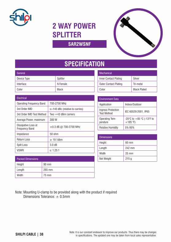
SHILPI CABLE | 38Note: It is our constant endeavor to improve our products. Thus there may be changes
in specifications. The updated one may be taken from local sales representative.
2 WAY POWER SPLITTER
SAR2WSNF
Electrical
Operating Frequency Band 700-2700 MHz
3rd Order IMD -150 dBc (relative to carrier)
3rd Order IMD Test Method Two +43 dBm carriers
Average Power, maximum 300 W
Dissipative Loss at Frequency Band
±0.3 dB @ 700-2700 MHz
Impedance 50 ohm
Return Loss 19.1 dB
Split Loss 3.0 dB
VSWR 1.25:1
General
Device Type Splitter
elameF N ecafretnI
kcalBroloC
Environment Data
Application Indoor/Outdoor
Ingress Protection Test Method
IEC 60529:2001, IP65
Operating Tem-perature
-25°C to +85 °C (-13°F to +185 °F)
Relative Humidity 5%-95%
Dimensions
Height 60 mm
Length 242 mm
Net Weight 215 g
Width 25 mmPacked Dimensions
Height 90 mm
Length 265 mm
Width 75 mm
Mechanical
Inner Contact Plating Silver
Outer Contact Plating Tri-metal
Color Black Plated
SPECIFICATION
Note: Mounting U-clamp to be provided along with the product if required Dimensions Tolerance: ± 0.5mm
2 WAY POWER SPLITTER
SAR2WSNF
≤-140dBc(relativetocarries)
3 WAY POWER SPLITTER
SAR3WSNF
Electrical
Operating Frequency Band 700-2700 MHz
3rd Order IMD -150 dBc (relative to carrier)
3rd Order IMD Test Method Two +43 dBm carriers
Average Power, maximum 300 W
Dissipative Loss at Frequency Band
±0.4 dB @ 700-2700 MHz
Impedance 50 ohm
Return Loss ≥19.1 dB
Split Loss 4.8 dB
VSWR 1.25:1
General
Device Type Splitter
elameF N ecafretnI
kcalBroloC
Environment Data
Application Indoor/Outdoor
Ingress Protection Test Method
IEC 60529:2001, IP65
Operating Tem-perature
-25°C to +85 °C (-13°F to +185 °F)
Relative Humidity 5%-95%
Dimensions
Height 60 mm
Length 266 mm
Net Weight 250 g
Width 25 mmPacked Dimensions
Height 90 mm
Length 265 mm
Width 75 mm
Mechanical
Inner Contact Plating Silver
Outer Contact Plating Tri-metal
Color Black Plated
SPECIFICATION
Note: Mounting U-clamp to be provided along with the product if required Dimensions Tolerance: ± 0.5mm
≥19.1dbm
≤1.25:1
215gNetWeight
25mmWidth
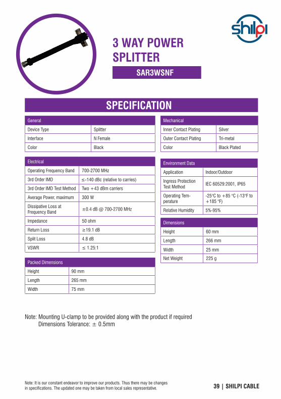
39 | SHILPI CABLE Note: It is our constant endeavor to improve our products. Thus there may be changes in specifications. The updated one may be taken from local sales representative.
2 WAY POWER SPLITTER
SAR2WSNF
Electrical
Operating Frequency Band 700-2700 MHz
3rd Order IMD -150 dBc (relative to carrier)
3rd Order IMD Test Method Two +43 dBm carriers
Average Power, maximum 300 W
Dissipative Loss at Frequency Band
±0.3 dB @ 700-2700 MHz
Impedance 50 ohm
Return Loss 19.1 dB
Split Loss 3.0 dB
VSWR 1.25:1
General
Device Type Splitter
elameF N ecafretnI
kcalBroloC
Environment Data
Application Indoor/Outdoor
Ingress Protection Test Method
IEC 60529:2001, IP65
Operating Tem-perature
-25°C to +85 °C (-13°F to +185 °F)
Relative Humidity 5%-95%
Dimensions
Height 60 mm
Length 242 mm
Net Weight 215 g
Width 25 mmPacked Dimensions
Height 90 mm
Length 265 mm
Width 75 mm
Mechanical
Inner Contact Plating Silver
Outer Contact Plating Tri-metal
Color Black Plated
SPECIFICATION
Note: Mounting U-clamp to be provided along with the product if required Dimensions Tolerance: ± 0.5mm
3 WAY POWER SPLITTER
SAR3WSNF
Electrical
Operating Frequency Band 700-2700 MHz
3rd Order IMD -150 dBc (relative to carrier)
3rd Order IMD Test Method Two +43 dBm carriers
Average Power, maximum 300 W
Dissipative Loss at Frequency Band
±0.4 dB @ 700-2700 MHz
Impedance 50 ohm
Return Loss ≥19.1 dB
Split Loss 4.8 dB
VSWR 1.25:1
General
Device Type Splitter
elameF N ecafretnI
kcalBroloC
Environment Data
Application Indoor/Outdoor
Ingress Protection Test Method
IEC 60529:2001, IP65
Operating Tem-perature
-25°C to +85 °C (-13°F to +185 °F)
Relative Humidity 5%-95%
Dimensions
Height 60 mm
Length 266 mm
Net Weight 250 g
Width 25 mmPacked Dimensions
Height 90 mm
Length 265 mm
Width 75 mm
Mechanical
Inner Contact Plating Silver
Outer Contact Plating Tri-metal
Color Black Plated
SPECIFICATION
Note: Mounting U-clamp to be provided along with the product if required Dimensions Tolerance: ± 0.5mm
SAR3WSNF
3 WAY POWER SPLITTER
≤-140dBc(relativetocarries)
≤1.25:1
225gNetWeight
25mmWidth

SHILPI CABLE | 40Note: It is our constant endeavor to improve our products. Thus there may be changes
in specifications. The updated one may be taken from local sales representative.
Note: Mounting U-clamp to be provided along with the product if required Dimensions Tolerance: ± 0.5mm
4 WAY POWER SPLITTER
SAR4WSNF
SPECIFICATION
Electrical
Operating Frequency Band 700-2700 MHz
3rd Order IMD -150 dBc (relative to carrier)
3rd Order IMD Test Method Two +43 dBm carriers
Average Power, maximum 300 W
Dissipative Loss at Frequency Band
± 0.5 dB @ 700-2700 MHz
Impedance 50 ohm
Return Loss ≥17.7 dB
Bd 0.6ssoL tilpS
1:3.1RWSV
General
Device Type Splitter
Interface N Female
thgiartSroloC
Environment
Application Indoor/Outdoor
Ingress Protection Test Method IEC 60529:2001, IP65
Operating Temperature-25°C to +85 °C (-13°F to +185 °F)
Relative Humidity 5%-95%
Dimensions
Height 60 mm
Length 266 mm
Net Weight 250 g
Width 25 mm
Packed Dimensions
Height 90 mm
Length 255 mm
Width 75 mm
Material and Finish
BodyBrass ( IS 319/89) /Tri Alloy
Insulator PTFE (ASTM D1710)
Inner ContactSRA Brass (IS 319/89)/ Silver over Tri Alloy
Gaskets Silicone Rubber
Other Metal PartsBrass (IS 319/89)/Tri Alloy Plating
Mechanical
Outer Contact Plating Silver
Inner Contact Plating Tri-metal
Color Black Plated
37 | SHILPI CABLE
4 WAY POWER SPLITTER
SAR4WSNF
≤-140dBc(relativetocarries)
≤1.3:1
250gNetWeight
25mmWidth
Note: Mounting U-clamp to be provided along with the product if required Dimensions Tolerance: ± 0.5mm
4 WAY POWER SPLITTER
SAR4WSNF
SPECIFICATION
Electrical
Operating Frequency Band 700-2700 MHz
3rd Order IMD -150 dBc (relative to carrier)
3rd Order IMD Test Method Two +43 dBm carriers
Average Power, maximum 300 W
Dissipative Loss at Frequency Band
± 0.5 dB @ 700-2700 MHz
Impedance 50 ohm
Return Loss ≥17.7 dB
Bd 0.6ssoL tilpS
1:3.1RWSV
General
Device Type Splitter
Interface N Female
thgiartSroloC
Environment
Application Indoor/Outdoor
Ingress Protection Test Method IEC 60529:2001, IP65
Operating Temperature-25°C to +85 °C (-13°F to +185 °F)
Relative Humidity 5%-95%
Dimensions
Height 60 mm
Length 266 mm
Net Weight 250 g
Width 25 mm
Packed Dimensions
Height 90 mm
Length 255 mm
Width 75 mm
Material and Finish
BodyBrass ( IS 319/89) /Tri Alloy
Insulator PTFE (ASTM D1710)
Inner ContactSRA Brass (IS 319/89)/ Silver over Tri Alloy
Gaskets Silicone Rubber
Other Metal PartsBrass (IS 319/89)/Tri Alloy Plating
Mechanical
Outer Contact Plating Silver
Inner Contact Plating Tri-metal
Color Black Plated
37 | SHILPI CABLE 41 | SHILPI CABLE

SHILPI CABLE | 42Note: It is our constant endeavor to improve our products. Thus there may be changes
in specifications. The updated one may be taken from local sales representative.SHILPI CABLE | 42
43 | SHILPI CABLE Note: It is our constant endeavor to improve our products. Thus there may be changes in specifications. The updated one may be taken from local sales representative.
COUPLER
43 | SHILPI CABLE
Passivedevicesthatpowermanyoftheworld’smostefficientwirelessnetworks.Bydeliver-ingperformanceandlongevity,ourpassivedeviceshelpoperatorsoptimizetheirOpExwhilemaximizing their network efficiency.
Oursplitters,couplers,tappersandterminationaremanufacturedtothehigheststandardstoensure that active components in the network function properly. Enable antennas to transmit and receive signals accurately, year after year Offerruggeddurabilitywellsuitedforindoorandoutdoorapplications Availableinwidefrequencyrangesandoptions
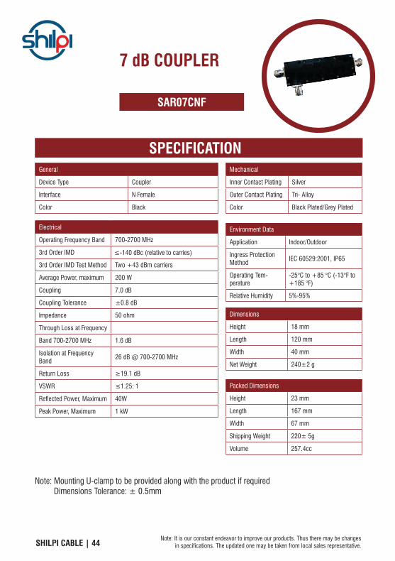
SHILPI CABLE | 44Note: It is our constant endeavor to improve our products. Thus there may be changes
in specifications. The updated one may be taken from local sales representative.
SAR07CNF
Electrical
Operating Frequency Band 700-2700 MHz
3rd Order IMD -140 dBc (relative to carrier)
3rd Order IMD Test Method Two +43 dBm carriers
Average Power, maximum 200 W
Coupling 7.0 dB
Coupling Tolerance ±0.8 dB
Impedance 50 ohm
Through Loss at Frequency
Band 700-2700 MHz 1.6 dB
Isolation at Frequency Band
26 dB @ 700-2700 MHz
Return Loss ≥19.1 dB
VSWR ≤1.25: 1
Reflected Power, Maximum 40W
Peak Power, Maximum 1 kW
General
Device Type Coupler
elameF N ecafretnI
kcalBroloC
Environment Data
Application Indoor/Outdoor
Ingress Protection Method
IEC 60529:2001, IP65
Operating Tem-perature
-25°C to +85 °C (-13°F to +185 °F)
Relative Humidity 5%-95%
Dimensions
Height 18 mm
Length 120 mm
Width 40 mm
Net Weight 240±2 g
Packed Dimensions
Height 23 mm
Length 167 mm
Width 67 mm
Shipping Weight 220± 5g
Volume 257.4cc
Mechanical
Inner Contact Plating Silver
Outer Contact Plating Tri- Alloy
Color Black Plated/Grey Plated
SPECIFICATION
Note: Mounting U-clamp to be provided along with the product if required Dimensions Tolerance: ± 0.5mm
7 dB COUPLER
39 | SHILPI CABLE
7 dB COUPLER
SAR07CNF
≤-140dBc(relativetocarries)
10 dB COUPLER
SAR10CNF
Electrical
Operating Frequency Band 700-2700 MHz
3rd Order IMD -150 dBc (relative to carrier)
3rd Order IMD Test Method Two +43 dBm carriers
Average Power, maximum 200 W
Coupling 10.0 dB
Coupling Tolerance ±1.0 dB
ImpedanceThrough Loss at Frequency
50 ohm
Band 700-2700 MHz ≤0.7 dB
Isolation at Frequency Band ≥30 dB @ 700-2700 MHz
Return Loss ≥19.1 dB
VSWR ≤1.25: 1
Reflected Power, Maximum 40W
Peak Power, Maximum 1 kW
General
Device Type Coupler
elameF NecafretnI
kcalBroloC
Environment
Application Indoor/Outdoor
Ingress Protection Test Method
IEC 60529:2001, IP65
Operating Temperature
-25°C to +85 °C (-13°F to +185 °F)
Relative Humidity 5%-95%
Dimensions
Height 18 mm
Length 120 mm
Width 40 mm
Net Weight 240±2 g
Packed Dimensions
Height 23 mm
Length 167 mm
Width 67 mm
Shipping Weight 220± 5g
Volume 257.4cc
Mechanical
Inner Contact Plating Silver
Outer Contact Plating Tri-metal
Color Black Plated/Grey Plated
SPECIFICATION
Note: Mounting U-clamp to be provided along with the product if required Dimensions Tolerance: ± 0.5mm

45 | SHILPI CABLE Note: It is our constant endeavor to improve our products. Thus there may be changes in specifications. The updated one may be taken from local sales representative.
SAR07CNF
Electrical
Operating Frequency Band 700-2700 MHz
3rd Order IMD -140 dBc (relative to carrier)
3rd Order IMD Test Method Two +43 dBm carriers
Average Power, maximum 200 W
Coupling 7.0 dB
Coupling Tolerance ±0.8 dB
Impedance 50 ohm
Through Loss at Frequency
Band 700-2700 MHz 1.6 dB
Isolation at Frequency Band
26 dB @ 700-2700 MHz
Return Loss ≥19.1 dB
VSWR ≤1.25: 1
Reflected Power, Maximum 40W
Peak Power, Maximum 1 kW
General
Device Type Coupler
elameF N ecafretnI
kcalBroloC
Environment Data
Application Indoor/Outdoor
Ingress Protection Method
IEC 60529:2001, IP65
Operating Tem-perature
-25°C to +85 °C (-13°F to +185 °F)
Relative Humidity 5%-95%
Dimensions
Height 18 mm
Length 120 mm
Width 40 mm
Net Weight 240±2 g
Packed Dimensions
Height 23 mm
Length 167 mm
Width 67 mm
Shipping Weight 220± 5g
Volume 257.4cc
Mechanical
Inner Contact Plating Silver
Outer Contact Plating Tri- Alloy
Color Black Plated/Grey Plated
SPECIFICATION
Note: Mounting U-clamp to be provided along with the product if required Dimensions Tolerance: ± 0.5mm
7 dB COUPLER
39 | SHILPI CABLE
10 dB COUPLER
SAR10CNF
Electrical
Operating Frequency Band 700-2700 MHz
3rd Order IMD -150 dBc (relative to carrier)
3rd Order IMD Test Method Two +43 dBm carriers
Average Power, maximum 200 W
Coupling 10.0 dB
Coupling Tolerance ±1.0 dB
ImpedanceThrough Loss at Frequency
50 ohm
Band 700-2700 MHz ≤0.7 dB
Isolation at Frequency Band ≥30 dB @ 700-2700 MHz
Return Loss ≥19.1 dB
VSWR ≤1.25: 1
Reflected Power, Maximum 40W
Peak Power, Maximum 1 kW
General
Device Type Coupler
elameF NecafretnI
kcalBroloC
Environment
Application Indoor/Outdoor
Ingress Protection Test Method
IEC 60529:2001, IP65
Operating Temperature
-25°C to +85 °C (-13°F to +185 °F)
Relative Humidity 5%-95%
Dimensions
Height 18 mm
Length 120 mm
Width 40 mm
Net Weight 240±2 g
Packed Dimensions
Height 23 mm
Length 167 mm
Width 67 mm
Shipping Weight 220± 5g
Volume 257.4cc
Mechanical
Inner Contact Plating Silver
Outer Contact Plating Tri-metal
Color Black Plated/Grey Plated
SPECIFICATION
Note: Mounting U-clamp to be provided along with the product if required Dimensions Tolerance: ± 0.5mm
10 dB COUPLER
SAR10CNF
≤-140dBc(relativetocarries)
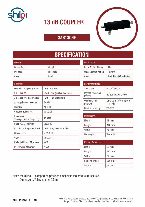
SHILPI CABLE | 46Note: It is our constant endeavor to improve our products. Thus there may be changes
in specifications. The updated one may be taken from local sales representative.
13 dB COUPLER
SAR13CNF
Electrical
Operating Frequency Band 700-2700 MHz
3rd Order IMD -150 dBc (relative to carrier)
3rd Order IMD Test Method Two +43 dBm carriers
Average Power, maximum 200 W
Coupling 13.0 dB
Coupling Tolerance ±1.0 dB
ImpedanceThrough Loss at Frequency
50 ohm
Band 700-2700 MHz ≤0.6 dB
Isolation at Frequency Band ≥35 dB @ 700-2700 MHz
Return Loss ≥19.1 dB
VSWR ≤1.25: 1
Reflected Power, Maximum 40W
Peak Power, Maximum 1 kW
General
Device Type Coupler
elameF N ecafretnI
kcalBroloC
Environment Data
Application Indoor/Outdoor
Ingress Protection Method
IEC 60529:2001, IP65
Operating Tem-perature
-25°C to +85 °C (-13°F to +185 °F)
Relative Humidity 5%-95%
Dimensions
Height 18 mm
Length 120 mm
Width 40 mm
Net Weight 240±2 g
Packed Dimensions
Height 23 mm
Length 167 mm
Width 67 mm
Shipping Weight 220± 5g
Volume 257.4cc
Mechanical
Inner Contact Plating Silver
Outer Contact Plating Tri-metal
Color Black Plated/Grey Plated
SPECIFICATION
Note: Mounting U-clamp to be provided along with the product if required Dimensions Tolerance: ± 0.5mm
41 | SHILPI CABLE
13 dB COUPLER
SAR13CNF
≤-140dBc(relativetocarries)
15 dB COUPLER
SAR15CNF
Electrical
Operating Frequency Band 700-2700 MHz
3rd Order IMD -150 dBc (relative to carrier)
3rd Order IMD Test Method Two +43 dBm carriers
Average Power, maximum 200 W
Coupling 15.0 dB
Coupling Tolerance ±1.0 dB
ImpedanceThrough Loss at Frequency
50 ohm
Band 700-2700 MHz ≤0.5 dB
Isolation at Frequency Band ≥35 dB @ 700-2700 MHz
Return Loss ≥19.1 dB
VSWR ≤1.25: 1
Reflected Power, Maximum 40W
Peak Power, Maximum 1 kW
General
Device Type Coupler
elameF NecafretnI
kcalBroloC
Environment
Application Indoor/Outdoor
Ingress Protection Test Method
IEC 60529:2001, IP65
Operating Temperature
-25°C to +85°C (-13°F to +185 °F)
Relative Humidity 5%-95%
Dimensions
Height 18 mm
Length 120 mm
Width 40 mm
Net Weight 240±2 g
Packed Dimensions
Height 23 mm
Length 167 mm
Width 67 mm
Shipping Weight 220± 5g
Volume 257.4cc
Mechanical
Inner Contact Plating Silver
Outer Contact Plating Tri-metal
Color Black Plated/Grey Plated
SPECIFICATION
Note: Mounting U-clamp to be provided along with the product if required Dimensions Tolerance: ± 0.5mm
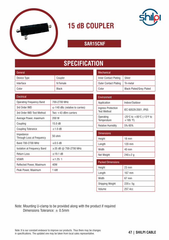
47 | SHILPI CABLE Note: It is our constant endeavor to improve our products. Thus there may be changes in specifications. The updated one may be taken from local sales representative.
13 dB COUPLER
SAR13CNF
Electrical
Operating Frequency Band 700-2700 MHz
3rd Order IMD -150 dBc (relative to carrier)
3rd Order IMD Test Method Two +43 dBm carriers
Average Power, maximum 200 W
Coupling 13.0 dB
Coupling Tolerance ±1.0 dB
ImpedanceThrough Loss at Frequency
50 ohm
Band 700-2700 MHz ≤0.6 dB
Isolation at Frequency Band ≥35 dB @ 700-2700 MHz
Return Loss ≥19.1 dB
VSWR ≤1.25: 1
Reflected Power, Maximum 40W
Peak Power, Maximum 1 kW
General
Device Type Coupler
elameF N ecafretnI
kcalBroloC
Environment Data
Application Indoor/Outdoor
Ingress Protection Method
IEC 60529:2001, IP65
Operating Tem-perature
-25°C to +85 °C (-13°F to +185 °F)
Relative Humidity 5%-95%
Dimensions
Height 18 mm
Length 120 mm
Width 40 mm
Net Weight 240±2 g
Packed Dimensions
Height 23 mm
Length 167 mm
Width 67 mm
Shipping Weight 220± 5g
Volume 257.4cc
Mechanical
Inner Contact Plating Silver
Outer Contact Plating Tri-metal
Color Black Plated/Grey Plated
SPECIFICATION
Note: Mounting U-clamp to be provided along with the product if required Dimensions Tolerance: ± 0.5mm
41 | SHILPI CABLE
15 dB COUPLER
SAR15CNF
Electrical
Operating Frequency Band 700-2700 MHz
3rd Order IMD -150 dBc (relative to carrier)
3rd Order IMD Test Method Two +43 dBm carriers
Average Power, maximum 200 W
Coupling 15.0 dB
Coupling Tolerance ±1.0 dB
ImpedanceThrough Loss at Frequency
50 ohm
Band 700-2700 MHz ≤0.5 dB
Isolation at Frequency Band ≥35 dB @ 700-2700 MHz
Return Loss ≥19.1 dB
VSWR ≤1.25: 1
Reflected Power, Maximum 40W
Peak Power, Maximum 1 kW
General
Device Type Coupler
elameF NecafretnI
kcalBroloC
Environment
Application Indoor/Outdoor
Ingress Protection Test Method
IEC 60529:2001, IP65
Operating Temperature
-25°C to +85°C (-13°F to +185 °F)
Relative Humidity 5%-95%
Dimensions
Height 18 mm
Length 120 mm
Width 40 mm
Net Weight 240±2 g
Packed Dimensions
Height 23 mm
Length 167 mm
Width 67 mm
Shipping Weight 220± 5g
Volume 257.4cc
Mechanical
Inner Contact Plating Silver
Outer Contact Plating Tri-metal
Color Black Plated/Grey Plated
SPECIFICATION
Note: Mounting U-clamp to be provided along with the product if required Dimensions Tolerance: ± 0.5mm
15 dB COUPLER
SAR15CNF
≤-140dBc(relativetocarries)

SHILPI CABLE | 48Note: It is our constant endeavor to improve our products. Thus there may be changes
in specifications. The updated one may be taken from local sales representative.
20 dB COUPLER
SAR20CNF
Electrical
Operating Frequency Band 700-2700 MHz
3rd Order IMD -150 dBc (relative to carrier)
3rd Order IMD Test Method Two +43 dBm carriers
Average Power, maximum 200 W
Coupling 20.0 dB
Coupling Tolerance ±1.0 dB
ImpedanceThrough Loss at Frequency
50 ohm
Band 700-2700 MHz ≤0.3 dB
Isolation at Frequency Band ≥35 dB @ 700-2700 MHz
Return Loss ≥19.1 dB
VSWR ≤1.25: 1
Reflected Power, Maximum 40W
Peak Power, Maximum 1 kW
General
Device Type Coupler
elameF NecafretnI
kcalBroloC
Environment
Application Indoor/Outdoor
Ingress Protection Test Method
IEC 60529:2001, IP65
Operating Temperature
-25°C to +85 °C (-13°F to +185 °F)
Relative Humidity 5%-95%
Dimensions
Height 18 mm
Length 120 mm
Width 40 mm
Net Weight 240±2 g
Packed Dimensions
Height 23 mm
Length 167 mm
Width 67 mm
Shipping Weight 220± 5g
Volume 257.4cc
Mechanical
Inner Contact Plating Silver
Outer Contact Plating Tri-metal
Color Black Plated/Grey Plated
SPECIFICATION
Note: Mounting U-clamp to be provided along with the product if required Dimensions Tolerance: ± 0.5mm
20 dB COUPLER
SAR20CNF
30 dB COUPLER
SAR30CNF
Electrical
Operating Frequency Band 700-2700 MHz
3rd Order IMD -140 dBc (relative to carrier)
3rd Order IMD Test Method Two +43 dBm carriers
Average Power, maximum 200 W
Coupling 30.0 dB
Coupling Tolerance ±1.0 dB
ImpedanceThrough Loss at Frequency
50 ohm
Band 700-2700 MHz ≤0.2 dB
Isolation at Frequency Band ≥35 dB @ 700-2700 MHz
Return Loss ≥19.1 dB
VSWR ≤1.25: 1
Reflected Power, Maximum 40W
Peak Power, Maximum 1 kW
General
Device Type Coupler
elameF NecafretnI
kcalBroloC
Environment
Application Indoor/Outdoor
Ingress Protection Test Method
IEC 60529:2001, IP65
Operating Temperature
-25°C to +85 °C (-13°F to +185 °F)
Relative Humidity 5%-95%
Dimensions
Height 18 mm
Length 120 mm
Width 40 mm
Net Weight 240±2 g
Packed Dimensions
Height 23 mm
Length 167 mm
Width 67 mm
Shipping Weight 220± 5g
Volume 257.4cc
Mechanical
Inner Contact Plating Silver
Outer Contact Plating Tri-metal
Color Black Plated/Grey Plated
NOITACIFICEPS NOITACIFICEPS
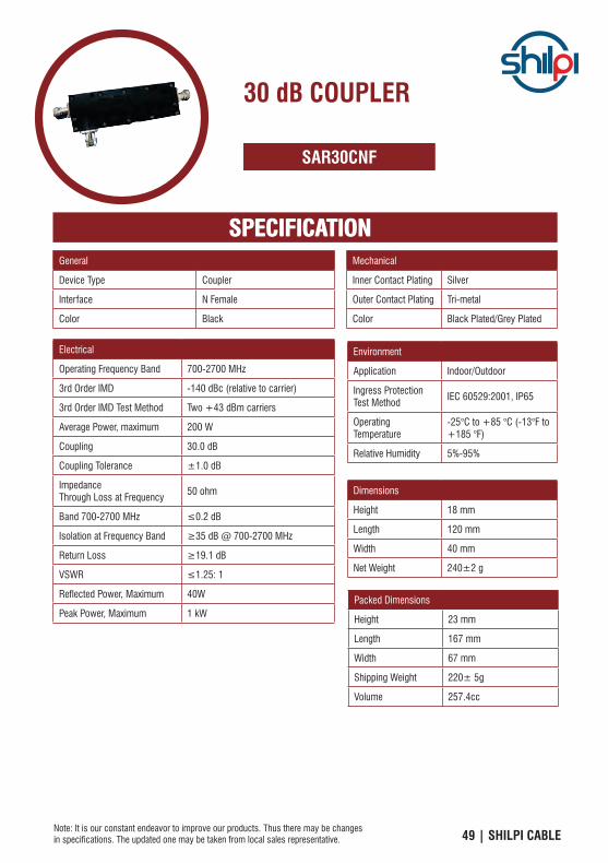
49 | SHILPI CABLE Note: It is our constant endeavor to improve our products. Thus there may be changes in specifications. The updated one may be taken from local sales representative.
20 dB COUPLER
SAR20CNF
Electrical
Operating Frequency Band 700-2700 MHz
3rd Order IMD -150 dBc (relative to carrier)
3rd Order IMD Test Method Two +43 dBm carriers
Average Power, maximum 200 W
Coupling 20.0 dB
Coupling Tolerance ±1.0 dB
ImpedanceThrough Loss at Frequency
50 ohm
Band 700-2700 MHz ≤0.3 dB
Isolation at Frequency Band ≥35 dB @ 700-2700 MHz
Return Loss ≥19.1 dB
VSWR ≤1.25: 1
Reflected Power, Maximum 40W
Peak Power, Maximum 1 kW
General
Device Type Coupler
elameF NecafretnI
kcalBroloC
Environment
Application Indoor/Outdoor
Ingress Protection Test Method
IEC 60529:2001, IP65
Operating Temperature
-25°C to +85 °C (-13°F to +185 °F)
Relative Humidity 5%-95%
Dimensions
Height 18 mm
Length 120 mm
Width 40 mm
Net Weight 240±2 g
Packed Dimensions
Height 23 mm
Length 167 mm
Width 67 mm
Shipping Weight 220± 5g
Volume 257.4cc
Mechanical
Inner Contact Plating Silver
Outer Contact Plating Tri-metal
Color Black Plated/Grey Plated
SPECIFICATION
Note: Mounting U-clamp to be provided along with the product if required Dimensions Tolerance: ± 0.5mm
30 dB COUPLER
SAR30CNF
Electrical
Operating Frequency Band 700-2700 MHz
3rd Order IMD -140 dBc (relative to carrier)
3rd Order IMD Test Method Two +43 dBm carriers
Average Power, maximum 200 W
Coupling 30.0 dB
Coupling Tolerance ±1.0 dB
ImpedanceThrough Loss at Frequency
50 ohm
Band 700-2700 MHz ≤0.2 dB
Isolation at Frequency Band ≥35 dB @ 700-2700 MHz
Return Loss ≥19.1 dB
VSWR ≤1.25: 1
Reflected Power, Maximum 40W
Peak Power, Maximum 1 kW
General
Device Type Coupler
elameF NecafretnI
kcalBroloC
Environment
Application Indoor/Outdoor
Ingress Protection Test Method
IEC 60529:2001, IP65
Operating Temperature
-25°C to +85 °C (-13°F to +185 °F)
Relative Humidity 5%-95%
Dimensions
Height 18 mm
Length 120 mm
Width 40 mm
Net Weight 240±2 g
Packed Dimensions
Height 23 mm
Length 167 mm
Width 67 mm
Shipping Weight 220± 5g
Volume 257.4cc
Mechanical
Inner Contact Plating Silver
Outer Contact Plating Tri-metal
Color Black Plated/Grey Plated
NOITACIFICEPS NOITACIFICEPS
30 dB COUPLER
SAR30CNF
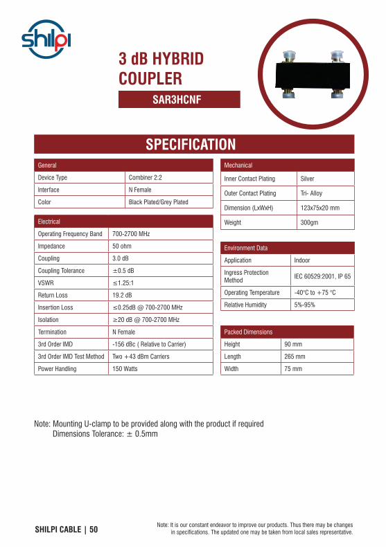
SHILPI CABLE | 50Note: It is our constant endeavor to improve our products. Thus there may be changes
in specifications. The updated one may be taken from local sales representative.
3 dB HYBRID COUPLER
SAR3HCNF
Electrical
Operating Frequency Band 700-2700 MHz
Impedance 50 ohm
Coupling 3.0 dB
Coupling Tolerance ±0.5 dB
VSWR ≤1.25:1
Return Loss 19.2 dB
Insertion Loss ≤0.25dB @ 700-2700 MHz
Isolation ≥20 dB @ 700-2700 MHz
Termination N Female
3rd Order IMD -156 dBc ( Relative to Carrier)
3rd Order IMD Test Method Two +43 dBm Carriers
Power Handling 150 Watts
General
Device Type Combiner 2:2
elameF N ecafretnI
detalP yerG/detalP kcalBroloC
Environment Data
Application Indoor
Ingress Protection Method
IEC 60529:2001, IP 65
Operating Temperature -40°C to +75 °C
Relative Humidity 5%-95%
Packed Dimensions
Height 90 mm
Length 265 mm
Width 75 mm
Mechanical
Inner Contact Plating Silver
Outer Contact Plating Tri- Alloy
Dimension (LxWxH) 123x75x20 mm
Weight 300gm
SPECIFICATION
Note: Mounting U-clamp to be provided along with the product if required Dimensions Tolerance: ± 0.5mm
3 dB HYBRID COUPLER
SAR3HCNF

3 dB HYBRID COUPLER
SAR3HCNF
Electrical
Operating Frequency Band 700-2700 MHz
Impedance 50 ohm
Coupling 3.0 dB
Coupling Tolerance ±0.5 dB
VSWR ≤1.25:1
Return Loss 19.2 dB
Insertion Loss ≤0.25dB @ 700-2700 MHz
Isolation ≥20 dB @ 700-2700 MHz
Termination N Female
3rd Order IMD -156 dBc ( Relative to Carrier)
3rd Order IMD Test Method Two +43 dBm Carriers
Power Handling 150 Watts
General
Device Type Combiner 2:2
elameF N ecafretnI
detalP yerG/detalP kcalBroloC
Environment Data
Application Indoor
Ingress Protection Method
IEC 60529:2001, IP 65
Operating Temperature -40°C to +75 °C
Relative Humidity 5%-95%
Packed Dimensions
Height 90 mm
Length 265 mm
Width 75 mm
Mechanical
Inner Contact Plating Silver
Outer Contact Plating Tri- Alloy
Dimension (LxWxH) 123x75x20 mm
Weight 300gm
SPECIFICATION
Note: Mounting U-clamp to be provided along with the product if required Dimensions Tolerance: ± 0.5mm
51 | SHILPI CABLE

SHILPI CABLE | 52Note: It is our constant endeavor to improve our products. Thus there may be changes
in specifications. The updated one may be taken from local sales representative.SHILPI CABLE | 52

53 | SHILPI CABLE Note: It is our constant endeavor to improve our products. Thus there may be changes in specifications. The updated one may be taken from local sales representative. 53 | SHILPI CABLE
COMBINER / DIPLEXER / TRIPLEXERRFconditioningproductsthatmakeiteasierforoperatorstoexpandtheirnetworksandrolloutnewtechnologies.Bydeployingourwidearrayofproducts,operatorscanboostdatathroughput, enhance coverage and reduce signal noise.Wedesignandmanufacturemulti-bandandsame-bandcombiners Save tower space and load Deployfasterwithamorevisuallyappealingsolution
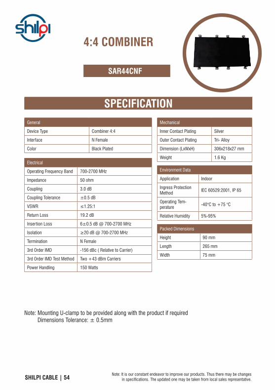
SHILPI CABLE | 54Note: It is our constant endeavor to improve our products. Thus there may be changes
in specifications. The updated one may be taken from local sales representative.
SAR44CNF
Electrical
Operating Frequency Band 700-2700 MHz
Impedance 50 ohm
Coupling 3.0 dB
Coupling Tolerance ±0.5 dB
VSWR ≤1.25:1
Return Loss 19.2 dB
Insertion Loss 6±0.5 dB @ 700-2700 MHz
Isolation ≥20 dB @ 700-2700 MHz
Termination N Female
3rd Order IMD -156 dBc ( Relative to Carrier)
3rd Order IMD Test Method Two +43 dBm Carriers
Power Handling 150 Watts
General
Device Type Combiner 4:4
elameF N ecafretnI
detalP kcalBroloC
Environment Data
Application Indoor
Ingress Protection Method
IEC 60529:2001, IP 65
Operating Tem-perature
-40°C to +75 °C
Relative Humidity 5%-95%
Packed Dimensions
Height 90 mm
Length 265 mm
Width 75 mm
Mechanical
Inner Contact Plating Silver
Outer Contact Plating Tri- Alloy
Dimension (LxWxH) 306x218x27 mm
Weight 1.6 Kg
SPECIFICATION
Note: Mounting U-clamp to be provided along with the product if required Dimensions Tolerance: ± 0.5mm
4:4 COMBINER4:4 COMBINER
SAR44CNF
SPECIFICATION

55 | SHILPI CABLE Note: It is our constant endeavor to improve our products. Thus there may be changes in specifications. The updated one may be taken from local sales representative.
SAR44CNF
Electrical
Operating Frequency Band 700-2700 MHz
Impedance 50 ohm
Coupling 3.0 dB
Coupling Tolerance ±0.5 dB
VSWR ≤1.25:1
Return Loss 19.2 dB
Insertion Loss 6±0.5 dB @ 700-2700 MHz
Isolation ≥20 dB @ 700-2700 MHz
Termination N Female
3rd Order IMD -156 dBc ( Relative to Carrier)
3rd Order IMD Test Method Two +43 dBm Carriers
Power Handling 150 Watts
General
Device Type Combiner 4:4
elameF N ecafretnI
detalP kcalBroloC
Environment Data
Application Indoor
Ingress Protection Method
IEC 60529:2001, IP 65
Operating Tem-perature
-40°C to +75 °C
Relative Humidity 5%-95%
Packed Dimensions
Height 90 mm
Length 265 mm
Width 75 mm
Mechanical
Inner Contact Plating Silver
Outer Contact Plating Tri- Alloy
Dimension (LxWxH) 306x218x27 mm
Weight 1.6 Kg
SPECIFICATION
Note: Mounting U-clamp to be provided along with the product if required Dimensions Tolerance: ± 0.5mm
4:4 COMBINER
Electrical
Frequencyrange 1800MHz…8Ports 2100MHz…4Ports 4G……….2Ports WI-Max….2Ports
GSM1800:1710~1785MHz&1805-1880MHz(2G)
UMTS:2100:1920~1980MHz&2110~2170MHz(3G)
LTE2300-2400MHzWI-Max2400-2500MHz(4G)
Band-width(BW) GSM1800:75MHz|UMTS2100:60MHz|4G:100MHz|WI-Max:100MHz
InsertionLoss GSM1800:12dBi|UMTS2100:12dBi|4G:12dBi|WI-Max:12dBi
PassbandRipple ±0.5dB
ReturnLoss BetterThan18dB
Isolation 75dBoutband|20dBinband
PassiveIntermpodulation ≤143dBc@43dBmx2
In/OutPort DIN(F)orN(F)Customized
I/P&O/Pports 16forinput&4forO/P(Allportsonfrontside)
In/OutImpedance 50Ohm
Temperaturerange -100 Cto+650C
PowerHandlingCapacity I/P:50Wattseachport,O/P:450Watts
16:4 COMBINER / POI
SCTL 14-040-160-000
CHARACTERISTICS: General SpecificationsDevice Type:Combiner16:4|Interface: DinFemale/NFemale|Color: BlackPlated
General
DeviceTyep Combiner4:4
Interface NFemale
Color BlackPlated
SPECIFICATIONMechanical
Temperaturerange -100to+650C
OperatingTemperature(INDOOR)
-5degreeC~+55degreeC(ambient)
StorageTemperature -10degreeC~+65degreeC(ambient)
Humidity 95%
Environmental
MountingType RackMounting
EnclosureLock Screws
HeatDissipation NaturalConvection
DimensionsTolerance:±0.5mm

SHILPI CABLE | 56Note: It is our constant endeavor to improve our products. Thus there may be changes
in specifications. The updated one may be taken from local sales representative.
DIPLEXER FILTER 900/UMTS BAND
SCTL D900-000-210
DimensionsTolerance:±0.5mm
SPECIFICATIONElectrical
Type CavityType
FrequencyRange(FullRange) 890-960/1920-2170MHz
UplinkFrequencyRange 890-915/1920-1980MHz
DownlinkFrequencyRange 935-960/2110-2170MHz
Impedance 50ohm
VSWR 1.3:1
InsertionLoss 0.4dBTypical,0.5dBMaximum
Isolation(Port1to2,Port2to1) 50dBcminimum
Termination DINFemaleLongNeck
IMD@43dBmPower -140dBc
PowerHandling 250WattsAverage,3KwPeak
Environment
LighteningProtection 20kA,8/20μs
EnvironmentalProtec-tion
Indoor/OutdoortoIP67
OperatingTemperature -40°Cto+75°C
RelativeHumidity 5%-95%
Mechanical
HousingAluminumWithSilverPlating
MountingKitHoseClampsinStainless Steel
MTBF 10millionHours
Weight 2.2Kg
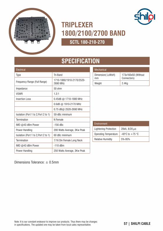
57 | SHILPI CABLE Note: It is our constant endeavor to improve our products. Thus there may be changes in specifications. The updated one may be taken from local sales representative.
DimensionsTolerance:±0.5mm
SPECIFICATIONElectrical
Type Tri-Band
FrequencyRange(FullRange)1710-1880/1910-2170/2520-2690MHz
Impedance 50ohm
VSWR 1.3:1
InsertionLoss 0.45dB@1710-1880MHz
0.6dB@1910-2170MHz
0.75dB@2520-2690MHz
Isolation(Port1to2,Port2to1) 50-dBcminimum
Termination NFemale
IMD@43dBmPower -156dBc
PowerHandling 200WattsAverage,3KwPeak
Isolation(Port1to2,Port2to1) 60dBcminimum
Termination 7/16DinFemaleLongNeck
IMD@43dBmPower -110dBm
PowerHandling 250WattsAverage,3KwPeak
Environment
LighteningProtection 20kA,8/20μs
OperatingTemperature -40°Cto+75°C
RelativeHumidity 5%-95%
Mechanical
Dimension(LxWxH)mm
173x160x50(WithoutConnectors)
Weight 2.4Kg
TRIPLEXER 1800/2100/2700 BAND
SCTL 180-210-270

SHILPI CABLE | 58Note: It is our constant endeavor to improve our products. Thus there may be changes
in specifications. The updated one may be taken from local sales representative.
DIPLEXER FILTER 900/1800/UMTS BAND
DimensionsTolerance:±0.5mm
SCTL D 180-000-210
SPECIFICATIONElectrical
Type CavityType
FrequencyRange(FullRange) 1710-1785/1920-2170MHz
UplinkFrequencyRange 1710-1785/1920-1980MHz
DownlinkFrequencyRange 1805-1880/2110-2170MHz
Impedance 50ohm
VSWR 1.3:1
InsertionLoss 0.4dBTypical,0.5dBMaximum
Isolation(Port1to2,Port2to1) 50dBcminimum
Termination DINFemaleLongNeck
IMD@43dBmPower -160dBc
PowerHandling 250WattsAverage,3KwPeak
Environment
LighteningProtection 20kA,8/20μs
EnvironmentalProtec-tion
Indoor/OutdoortoIP67
OperatingTemperature -40°Cto+75°C
RelativeHumidity 5%-95%
Mechanical
Dimension(LxWxH)mm
242x106x48(WithoutConnectors)
HousingAluminiumWithSilverPlating
MountingKitHoseClampsinStainless Steel
MTBF 10millionHours
Weight 2.2Kg
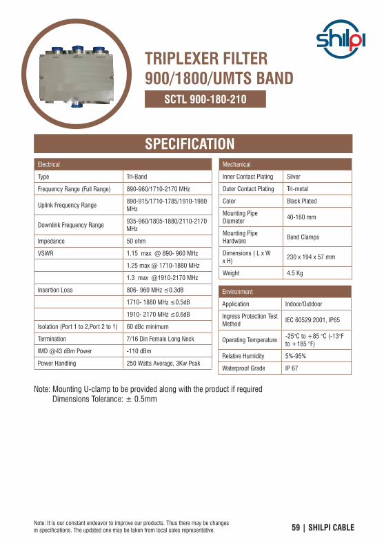
59 | SHILPI CABLE Note: It is our constant endeavor to improve our products. Thus there may be changes in specifications. The updated one may be taken from local sales representative.
Note:MountingU-clamptobeprovidedalongwiththeproductifrequiredDimensionsTolerance:±0.5mm
TRIPLEXER FILTER 900/1800/UMTS BAND
SCTL 900-180-210
SPECIFICATIONElectrical
Type Tri-Band
FrequencyRange(FullRange) 890-960/1710-2170MHz
UplinkFrequencyRange890-915/1710-1785/1910-1980MHz
DownlinkFrequencyRange935-960/1805-1880/2110-2170MHz
Impedance 50ohm
VSWR 1.15max@890-960MHz
1.25max@1710-1880MHz
1.3max@1910-2170MHz
InsertionLoss 806-960MHz≤0.3dB
1710-1880MHz≤0.5dB
1910-2170MHz≤0.6dB
Isolation(Port1to2,Port2to1) 60dBcminimum
Termination 7/16DinFemaleLongNeck
IMD@43dBmPower -110dBm
PowerHandling 250WattsAverage,3KwPeak
Environment
Application Indoor/Outdoor
IngressProtectionTestMethod
IEC60529:2001,IP65
OperatingTemperature-25°Cto+85°C(-13°Fto+185°F)
RelativeHumidity 5%-95%
Waterproof Grade IP67
Mechanical
InnerContactPlating Silver
OuterContactPlating Tri-metal
Color BlackPlated
MountingPipeDiameter
40-160mm
MountingPipeHardware
BandClamps
Dimensions(LxWxH)
230x194x57mm
Weight 4.5Kg

SHILPI CABLE | 60Note: It is our constant endeavor to improve our products. Thus there may be changes
in specifications. The updated one may be taken from local sales representative.SHILPI CABLE | 60
61 | SHILPI CABLE Note: It is our constant endeavor to improve our products. Thus there may be changes in specifications. The updated one may be taken from local sales representative. 61 | SHILPI CABLE
Engineered to stop signal reflection, reduce interference and increase the stability of RFsignals, terminators are the smart way to cap off your end points.
ATTENUATORDUMMY LOAD/TERMINATOR
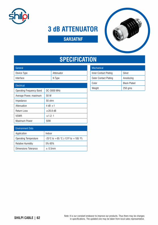
SHILPI CABLE | 62Note: It is our constant endeavor to improve our products. Thus there may be changes
in specifications. The updated one may be taken from local sales representative. SHILPI CABLE |
6 dB ATTENUATOR
SAR6ATNF
Electrical
Operating Frequency Band DC-3000 MHz
Average Power, maximum 50 W
Impedance 50 ohm
Attenuation 7 dB ±1
Return Loss ≥20.8 dB
VSWR ≤1.2: 1
Maximum Power 50W
General
Device Type Attenuator
Interface N Type
Environment Data
Application Indoor
Operating Temperature -25°C to +85 °C (-13°F to +185 °F)
Relative Humidity 5%-95%
Dimensions Tolerance ± 0.5mm
Mechanical
Inner Contact Plating Silver
Outer Contact Plating Anodozing
Color Black Plated
Weight 250 gms
SPECIFICATION
53
3 dB ATTENUATORSAR3ATNF
SHILPI CABLE |
SAR3ATNF
Electrical
Operating Frequency Band DC-3000 MHz
Average Power, maximum 50 W
Impedance 50 ohm
Attenuation 4 dB ±1
Return Loss ≥20.8 dB
VSWR ≤1.2: 1
Maximum Power 50W
General
Device Type Attenuator
Interface N Type
Environment Data
Application Indoor
Operating Temperature -25°C to +85 °C (-13°F to +185 °F)
Relative Humidity 5%-95%
Dimensions Tolerance ± 0.5mm
Mechanical
Inner Contact Plating Silver
Outer Contact Plating Anodozing
Color Black Plated
Weight 250 gms
Material Data
Cable
Inner Conductor Copper Clad Aluminum
Dielectric Foamed Polyethylene
Outer ConductorCorrugated Copper Tubing with Black Polyethylene Jacket
Connector
Body Brass (ASTM B 16) / Tri Alloy
InsulatorPTFE (ASTM D1457, Type 1. Grade 1)
Centre ContactStress Relived Brass –Tri Alloy Silver Plated
Outer Contact Brass-Tri Alloy Plated
Gasket Silicone Rubber
SPECIFICATION
3 dB ATTENUATOR
52
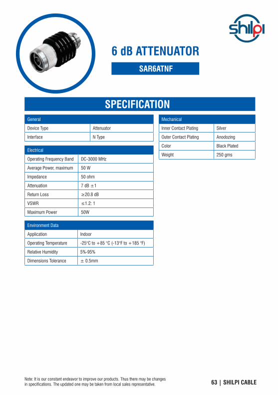
63 | SHILPI CABLE Note: It is our constant endeavor to improve our products. Thus there may be changes in specifications. The updated one may be taken from local sales representative.SHILPI CABLE |
6 dB ATTENUATOR
SAR6ATNF
Electrical
Operating Frequency Band DC-3000 MHz
Average Power, maximum 50 W
Impedance 50 ohm
Attenuation 7 dB ±1
Return Loss ≥20.8 dB
VSWR ≤1.2: 1
Maximum Power 50W
General
Device Type Attenuator
Interface N Type
Environment Data
Application Indoor
Operating Temperature -25°C to +85 °C (-13°F to +185 °F)
Relative Humidity 5%-95%
Dimensions Tolerance ± 0.5mm
Mechanical
Inner Contact Plating Silver
Outer Contact Plating Anodozing
Color Black Plated
Weight 250 gms
SPECIFICATION
53
6 dB ATTENUATORSAR6ATNF

SHILPI CABLE | 64Note: It is our constant endeavor to improve our products. Thus there may be changes
in specifications. The updated one may be taken from local sales representative.SHILPI CABLE |
Note: Dimensions Tolerance: ± 0.5mm
SA2WDLNF
Electrical
Operating Frequency Band DC-3000 MHz
Average Power, maximum 2W
3rd Order IMD-120 dBc( Relative to Carrier)
3rd Order IMD Test Method Two +43 dBm Carriers
Impedance 50 ohm
Return Loss ≥20.8 dB
VSWR ≤1.2: 1
General
Device Type Dummy Load/Terminator
Interface N Type
Color Nickel Plated
Environment
Application Indoor
Operating Temperature-25°C to +85 °C (-13°F to +185 °F)
Relative Humidity 5%-95%
Mechanical
Inner Contact Plating Silver
Outer Contact Plating Nickel Plated
Color Nickel Plated
Dimension Dia 20 x 30 mm
Weight 40 gms
SPECIFICATION
2 WATT DUMMY LOAD/ TERMINATOR
54
Note: Dimensions Tolerance: ± 0.5mm
5 WATT DUMMY LOAD/ TERMINATOR
SA5WDLNF
SPECIFICATION
Electrical
Operating Frequency Band DC-3000 MHz
Average Power, maximum 5 W
3rd Order IMD -120 dBc( Relative to Carrier)
3rd Order IMD Test Method Two +43 dBm Carriers
Impedance 50 ohm
Return Loss ≥20.8 dB
VSWR ≤1.2: 1
General
Device Type Dummy Load/Terminator
Interface N Type
Color Nickel Plated
Environment
Application Indoor
Operating Temperature-25°C to +85 °C (-13°F to +185 °F)
Relative Humidity 5%-95%
Mechanical
Inner Contact Plating Silver
Outer Contact Plating Anodozing
Color Black Plated
Dimension Dia 30 x 48mm
Weight 60 gms
55 | SHILPI CABLE
2 WATT DUMMY LOAD/TERMINATOR
SA2WDLNF

65 | SHILPI CABLE Note: It is our constant endeavor to improve our products. Thus there may be changes in specifications. The updated one may be taken from local sales representative.SHILPI CABLE |
Note: Dimensions Tolerance: ± 0.5mm
SA2WDLNF
Electrical
Operating Frequency Band DC-3000 MHz
Average Power, maximum 2W
3rd Order IMD-120 dBc( Relative to Carrier)
3rd Order IMD Test Method Two +43 dBm Carriers
Impedance 50 ohm
Return Loss ≥20.8 dB
VSWR ≤1.2: 1
General
Device Type Dummy Load/Terminator
Interface N Type
Color Nickel Plated
Environment
Application Indoor
Operating Temperature-25°C to +85 °C (-13°F to +185 °F)
Relative Humidity 5%-95%
Mechanical
Inner Contact Plating Silver
Outer Contact Plating Nickel Plated
Color Nickel Plated
Dimension Dia 20 x 30 mm
Weight 40 gms
SPECIFICATION
2 WATT DUMMY LOAD/ TERMINATOR
54
Note: Dimensions Tolerance: ± 0.5mm
5 WATT DUMMY LOAD/ TERMINATOR
SA5WDLNF
SPECIFICATION
Electrical
Operating Frequency Band DC-3000 MHz
Average Power, maximum 5 W
3rd Order IMD -120 dBc( Relative to Carrier)
3rd Order IMD Test Method Two +43 dBm Carriers
Impedance 50 ohm
Return Loss ≥20.8 dB
VSWR ≤1.2: 1
General
Device Type Dummy Load/Terminator
Interface N Type
Color Nickel Plated
Environment
Application Indoor
Operating Temperature-25°C to +85 °C (-13°F to +185 °F)
Relative Humidity 5%-95%
Mechanical
Inner Contact Plating Silver
Outer Contact Plating Anodozing
Color Black Plated
Dimension Dia 30 x 48mm
Weight 60 gms
55 | SHILPI CABLE
5 WATT DUMMY LOAD/TERMINATOR
SA5WDLNF
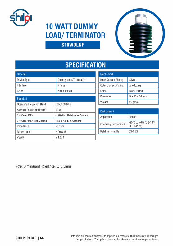
SHILPI CABLE | 66Note: It is our constant endeavor to improve our products. Thus there may be changes
in specifications. The updated one may be taken from local sales representative.
Note: Dimensions Tolerance: ± 0.5mm
10 WATT DUMMY LOAD/ TERMINATOR
S10WDLNF
SPECIFICATION
Electrical
Operating Frequency Band DC-3000 MHz
Average Power, maximum 10 W
3rd Order IMD -120 dBc( Relative to Carrier)
3rd Order IMD Test Method Two +43 dBm Carriers
Impedance 50 ohm
Return Loss ≥20.8 dB
VSWR ≤1.2: 1
General
Device Type Dummy Load/Terminator
Interface N Type
Color Nickel Plated
Environment
Application Indoor
Operating Temperature-25°C to +85 °C (-13°F to +185 °F)
Relative Humidity 5%-95%
Mechanical
Inner Contact Plating Silver
Outer Contact Plating Anodozing
Color Black Plated
Dimension Dia 35 x 56 mm
Weight 90 gms
56 | SHILPI CABLE
10 WATT DUMMY LOAD/ TERMINATOR
S10WDLNF

67 | SHILPI CABLE Note: It is our constant endeavor to improve our products. Thus there may be changes in specifications. The updated one may be taken from local sales representative.
Note: Dimensions Tolerance: ± 0.5mm
10 WATT DUMMY LOAD/ TERMINATOR
S10WDLNF
SPECIFICATION
Electrical
Operating Frequency Band DC-3000 MHz
Average Power, maximum 10 W
3rd Order IMD -120 dBc( Relative to Carrier)
3rd Order IMD Test Method Two +43 dBm Carriers
Impedance 50 ohm
Return Loss ≥20.8 dB
VSWR ≤1.2: 1
General
Device Type Dummy Load/Terminator
Interface N Type
Color Nickel Plated
Environment
Application Indoor
Operating Temperature-25°C to +85 °C (-13°F to +185 °F)
Relative Humidity 5%-95%
Mechanical
Inner Contact Plating Silver
Outer Contact Plating Anodozing
Color Black Plated
Dimension Dia 35 x 56 mm
Weight 90 gms
56 | SHILPI CABLE
50 WATT DUMMY LOAD/ TERMINATOR
Note:DimensionsTolerance:±0.5mm
SCTL 11 270-250-000
Electrical
OperatingFrequencyBand DC-3000MHz
AveragePower,maximum 50W
3rdOrderIMD-120dBc(RelativetoCarrier)
3rdOrderIMDTestMethod Two+43dBmCarriers
Impedance 50ohm
ReturnLoss ≥20.8dB
VSWR ≤1.2:1
General
DeviceType DummyLoad/Terminator
Interface DIN(F)Type
Color Black
Environment
Application Indoor
OperatingTemperature-35°Cto+85°C(-13°Fto+185°F)
RelativeHumidity 5%-95%
Mechanical
InnerContactPlating Silver
OuterContactPlating Anodozing
Color BlackPlated
Weight 1200gms
SPECIFICATION
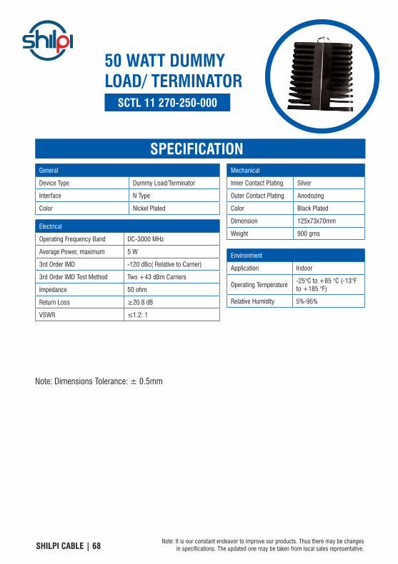
SHILPI CABLE | 68Note: It is our constant endeavor to improve our products. Thus there may be changes
in specifications. The updated one may be taken from local sales representative.
Note:DimensionsTolerance:±0.5mm
50 WATT DUMMY LOAD/ TERMINATOR
SCTL 11 270-250-000
SPECIFICATION
Electrical
OperatingFrequencyBand DC-3000MHz
AveragePower,maximum 5W
3rdOrderIMD -120dBc(RelativetoCarrier)
3rdOrderIMDTestMethod Two+43dBmCarriers
Impedance 50ohm
ReturnLoss ≥20.8dB
VSWR ≤1.2:1
General
DeviceType DummyLoad/Terminator
Interface NType
Color NickelPlated
Environment
Application Indoor
OperatingTemperature-25°Cto+85°C(-13°Fto+185°F)
RelativeHumidity 5%-95%
Mechanical
InnerContactPlating Silver
OuterContactPlating Anodozing
Color BlackPlated
Dimension 125x73x70mm
Weight 900gms
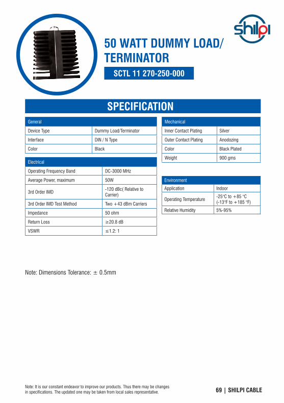
69 | SHILPI CABLE Note: It is our constant endeavor to improve our products. Thus there may be changes in specifications. The updated one may be taken from local sales representative.
50 WATT DUMMY LOAD/ TERMINATOR
Note:DimensionsTolerance:±0.5mm
SCTL 11 270-250-000
Electrical
OperatingFrequencyBand DC-3000MHz
AveragePower,maximum 50W
3rdOrderIMD-120dBc(RelativetoCarrier)
3rdOrderIMDTestMethod Two+43dBmCarriers
Impedance 50ohm
ReturnLoss ≥20.8dB
VSWR ≤1.2:1
General
DeviceType DummyLoad/Terminator
Interface DIN/NType
Color Black
Environment
Application Indoor
OperatingTemperature-25°Cto+85°C(-13°Fto+185°F)
RelativeHumidity 5%-95%
Mechanical
InnerContactPlating Silver
OuterContactPlating Anodozing
Color BlackPlated
Weight 900gms
SPECIFICATION

SHILPI CABLE | 70Note: It is our constant endeavor to improve our products. Thus there may be changes
in specifications. The updated one may be taken from local sales representative.SHILPI CABLE | 70

71 | SHILPI CABLE Note: It is our constant endeavor to improve our products. Thus there may be changes in specifications. The updated one may be taken from local sales representative.
ANTENNA
71 | SHILPI CABLE
Ourantennasaredesignedtoaddspotcoverageindifficult-to-coverareassuchasbuildings,parkinggarages,airportsandstadiums.ThesecompactandunobtrusiveDASantennasfea-tureamultibandfunctionthatenablesoperatorstouseawiderangeoffrequencieswithonesmallantenna.Eachantennaisdesignedtosupportallcurrentandfuture3Gapplicationsand engineered for high performance.

SHILPI CABLE | 72Note: It is our constant endeavor to improve our products. Thus there may be changes
in specifications. The updated one may be taken from local sales representative.
Note:DimensionsTolerance:±0.5mm
SPECIFICATION
Electrical
GainatFrequencyBand 2-5dBi
OperatingFrequencyBand 700-960/1710-2700MHz
Impedance 50ohm
HorizontalBeamwidth 360°OmniDirectional
VerticalBeamwidth 65°±10°
Polarization Vertical
3rdOrderIMD -140dBc(relativetocarrier)
3rdOrderIMDTestMethod Two+43dBmcarriers
InputPower,maximum 50W
PigTail RG58Length300mm
LighteningProtection DCGround
ReturnLoss ≥15.6dB
VSWR ≤1.5:1
General
DeviceType OmniAntenna
Interface NFemale
RadomeColor White/Grey
RadomeMaterial ABSUVResistant
Environment
Application Indoor
OperatingTemperature-25°Cto+85°C(-13°Fto+185°F)
RelativeHumidity 5%-95%
Mechanical
ReflectorMaterial AluminiumAlloy
MountingClamp would be provided
Dimension 185x85mm
Weight 220gms
CEILING MOUNT OMNI ANTENNA
SCTL 7 254-005-00F

73 | SHILPI CABLE Note: It is our constant endeavor to improve our products. Thus there may be changes in specifications. The updated one may be taken from local sales representative.
Note:DimensionsTolerance:±0.5mm
SPECIFICATION
Electrical
GainatFrequencyBand 2-5dBi
OperatingFrequencyBand 700-960/1710-2700MHz
Impedance 50ohm
HorizontalBeamwidth 360°OmniDirectional
VerticalBeamwidth 65°±10°
Polarization Vertical
3rdOrderIMD -140dBc(relativetocarrier)
3rdOrderIMDTestMethod Two+43dBmcarriers
InputPower,maximum 50W
PigTail RG58Length300mm
LighteningProtection DCGround
ReturnLoss ≥15.6dB
VSWR ≤1.5:1
General
DeviceType OmniAntenna
Interface NFemale
RadomeColor White/Grey
RadomeMaterial ABSUVResistant
Environment
Application Indoor
OperatingTemperature-25°Cto+85°C(-13°Fto+185°F)
RelativeHumidity 5%-95%
Mechanical
ReflectorMaterial AluminiumAlloy
MountingClamp would be provided
Dimension 185x85mm
Weight 290gms
CEILING MOUNT OMNI ANTENNA
SCTL 7 254-005-00R
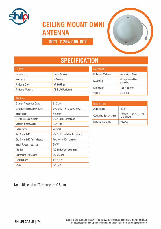
SHILPI CABLE | 74Note: It is our constant endeavor to improve our products. Thus there may be changes
in specifications. The updated one may be taken from local sales representative.
Note:DimensionsTolerance:±0.5mm
SPECIFICATION
Electrical
GainatFrequencyBand 2-5dBi
OperatingFrequencyBand 700-960/1710-2700MHz
Impedance 50ohm
HorizontalBeamwidth 360°OmniDirectional
VerticalBeamwidth 65°±10°
Polarization Vertical
3rdOrderIMD -140dBc(relativetocarrier)
3rdOrderIMDTestMethod Two+43dBmcarriers
InputPower,maximum 50W
PigTail RG58Length300mm
LighteningProtection DCGround
ReturnLoss ≥15.6dB
VSWR ≤1.5:1
General
DeviceType OmniAntenna
Interface NFemale
RadomeColor White/Grey
RadomeMaterial ABSUVResistant
Environment
Application Indoor
OperatingTemperature-25°Cto+85°C(-13°Fto+185°F)
RelativeHumidity 5%-95%
Mechanical
ReflectorMaterial AluminiumAlloy
MountingClamp would be provided
Dimension 185x85mm
Weight 290gms
CEILING MOUNT OMNI ANTENNA
SCTL 7 254-005-002
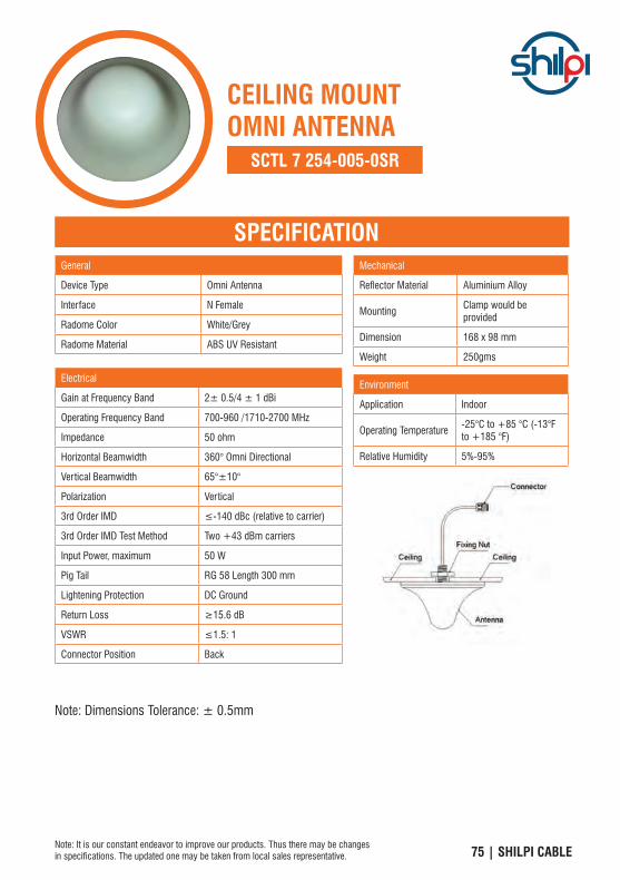
75 | SHILPI CABLE Note: It is our constant endeavor to improve our products. Thus there may be changes in specifications. The updated one may be taken from local sales representative.
Note:DimensionsTolerance:±0.5mm
SPECIFICATION
Electrical
GainatFrequencyBand 2±0.5/4±1dBi
OperatingFrequencyBand 700-960/1710-2700MHz
Impedance 50ohm
HorizontalBeamwidth 360°OmniDirectional
VerticalBeamwidth 65°±10°
Polarization Vertical
3rdOrderIMD ≤-140dBc(relativetocarrier)
3rdOrderIMDTestMethod Two+43dBmcarriers
InputPower,maximum 50W
PigTail RG58Length300mm
LighteningProtection DCGround
ReturnLoss ≥15.6dB
VSWR ≤1.5:1
ConnectorPosition Back
General
DeviceType OmniAntenna
Interface NFemale
RadomeColor White/Grey
RadomeMaterial ABSUVResistant
Environment
Application Indoor
OperatingTemperature-25°Cto+85°C(-13°Fto+185°F)
RelativeHumidity 5%-95%
Mechanical
ReflectorMaterial AluminiumAlloy
MountingClamp would be provided
Dimension 168x98mm
Weight 250gms
CEILING MOUNT OMNI ANTENNA
SCTL 7 254-005-0SR

SHILPI CABLE | 76Note: It is our constant endeavor to improve our products. Thus there may be changes
in specifications. The updated one may be taken from local sales representative.
SPECIFICATION
Electrical
GainatFrequencyBand6±1dBi@700-960MHz7±1dBi@1710-2700MHz
OperatingFrequencyBand 700-960/1710-2700MHz
Impedance 50ohm
HorizontalBeamwidth 110degree
VerticalBeamwidth 90degree
Polarization Vertical
3rdOrderIMD -140dBc(relativetocarrier)
3rdOrderIMDTestMethod Two+43dBmcarriers
InputPower,maximum 50W
PigTail RG58Length300mm
LighteningProtection DCGround
ReturnLoss ≥13.9dB
VSWR ≤1.5:1
General
DeviceType PanelAntennaDirectional
Interface NFemale
RadomeColor White/Grey
RadomeMaterial ABSUVResistant
Environment
Application Indoor
OperatingTemperature-25°Cto+85°C(-13°Fto+185°F)
RelatedWindVelocity(m/sec)
100
RelativeHumidity 5%-95%
Mechanical
ReflectorMaterial AluminiumAlloy
MountingClamp would be provided
Dimension 207x178x44mm
Weight 380gms
Note:DimensionsTolerance:±0.5mm
PATCH PANEL ANTENNA 7 DBI
SCTL 9 380-900-007

77 | SHILPI CABLE Note: It is our constant endeavor to improve our products. Thus there may be changes in specifications. The updated one may be taken from local sales representative.
Note:DimensionsTolerance:±0.5mm
SPECIFICATION
Electrical
GainatFrequencyBand 6±1dBi@700-960MHz
7±1dBi@1710-2700MHz
OperatingFrequencyBand 700-960/1710-2700MHz
Impedance 50ohm±5
BeamWidth,Horizontal 60°±10°
BeamWidth,Vertical 50°±10°
FronttoBackRatioat180° ≥15dB
Polarization Vertical
InputPower,maximum 150W
PigTail RG58Length520mm
LighteningProtection DCGround
ReturnLoss ≥13.9dB
VSWR ≤1.5:1
General
DeviceType YaglAntennaDirectional
Interface NFemale
RadomeColor White/Grey
RadomeMaterial ABSUVResistant
Environment
Application Indoor
OperatingTemperature-25°Cto+85°C(-13°Fto+185°F)
RelatedWindVelocity(Km/hr)
≥210
RelativeHumidity 5%-95%
Mechanical
ReflectorMaterial AluminiumAlloy
MountingClamp would be provided
Weight 490gms
YAGI ANTENNA 10 DBI
SAA10DNF

SHILPI CABLE | 78Note: It is our constant endeavor to improve our products. Thus there may be changes
in specifications. The updated one may be taken from local sales representative.SHILPI CABLE | 78

79 | SHILPI CABLE Note: It is our constant endeavor to improve our products. Thus there may be changes in specifications. The updated one may be taken from local sales representative. 79 | SHILPI CABLE
RF ACCESSORIESRFAccessoriesisusedintelecomsitesduringinstallationpurposes.TheKitscompriseofGroundingKit,WeatherProofKit,CableEntry,RFClamp,SurgeArrestor,Non-ReleasableCableTieetc.

SHILPI CABLE | 80Note: It is our constant endeavor to improve our products. Thus there may be changes
in specifications. The updated one may be taken from local sales representative.SHILPI CABLE |
SURGE ARRESTOR
SARSADMF
Lightning Surge current 30KA
Lightning Surge capability 100times@30KA
Speciafication
Frequency Range 0.8GHz~2.5GHz
VSWR ≤1.1@800-2500 MHz
Insertion Loss ≤ 0.1dB
Power(Max) 1000W
Insulation ≥1x10⁴MΩ
Impedance 50Ω
Current (KA@8/2μS)
Connector 7/16 Din(F), 7/16 Din(M)
68
SURGE ARRESTOR
SARSADMF

81 | SHILPI CABLE Note: It is our constant endeavor to improve our products. Thus there may be changes in specifications. The updated one may be taken from local sales representative.SHILPI CABLE |
SURGE ARRESTOR
SARSADMF
Lightning Surge current 30KA
Lightning Surge capability 100times@30KA
Speciafication
Frequency Range 0.8GHz~2.5GHz
VSWR ≤1.1@800-2500 MHz
Insertion Loss ≤ 0.1dB
Power(Max) 1000W
Insulation ≥1x10⁴MΩ
Impedance 50Ω
Current (KA@8/2μS)
Connector 7/16 Din(F), 7/16 Din(M)
68
RF CABLE CLAMP
SARCCLMP
APPLICATIONEach Cable Clamp product conforms to most or all brands coaxial cable and are designed to ulimately ease the installation process. Without additional adapters. these clamps can provide sturdy, reliable longtermsupporttosystembymeansoftoughandUVmaterial.
1x1/4”(Ø8)1x3/8”(Ø10.5)1x1/2”(Ø17)1x7/8”(Ø28)1x1-1/4”(Ø40)1x1-5/8”(Ø52)
3x1/2”(Ø17)3x7/8”(Ø28)3x1-1/4”(Ø40)3x1-5/8”(Ø52)
6x1/2”(Ø17)6x3/8”(Ø10.5)6x7/8”(Ø28)
2x1/4”(Ø8)2x3/8”(Ø10.5)2x1/2”(Ø17)2x7/8”(Ø28)2x1-1/4”(Ø40)2x1-5/8”(Ø52)
MaterialandSurfaceTreatment
Clamp PLasticcableclamp Polypropylene
C-Frame C-Frame StainlesssteelSUS304
Hardware Bolt,hexhut,flatwasher,bowlwasher,threadedrod StainlesssteelSUS304
EnvironmentalData
Temperature -55°Cto+75°C
Notice:PleasebecarefultoprotectthesurfaceofC-Frameandhardware.Shilpidisclaimsanyresposibilityfortheresultofimproperusage.

SHILPI CABLE | 82Note: It is our constant endeavor to improve our products. Thus there may be changes
in specifications. The updated one may be taken from local sales representative.SHILPI CABLE |
CABLE ENTRY
SARCETRY
APPLICATION:Cable entry gives you convenience to install more cables in less space, consists of an entry frame and entry seal modules. Each seal module consists of two halves of flexible material matching the different type cable. The seal module is tighened, sealing the entry, that marks the result cable definitely should be compact, watertight, and operation can be opened and resealed as necessary to upgrade system, so it supports your future growth, changes configurations, or perform maintenance.
SHILPI can provide all kinds of cable entry as per customers requirement.
Cable Boot inserts are designed plugs for unused cushion holes. Cable Boot inserts are available to accomodate coaxial cable and allows for future expansions.
Cable Boot Cushion Plugs for 1/ 2” cablesCable Boot Cushion Plugs for 7/8 ” cablesCable Boot Cushion Plugs for 1 1/4” cablesCable Boot Cushion Plugs for 1 5/8” cables
Cable Entry Plates with round ports are easy to install solution when you require multiple entries for a variety cable
4”Cable Entry Plate, 1Port4”Cable Entry Plate, 2Port4”Cable Entry Plate, 3Port4”Cable Entry Plate, 4Port4”Cable Entry Plate, 5Port4”Cable Entry Plate, 6Port4”Cable Entry Plate, 12Port4”Cable Entry Plate, 12Port4”Cable Entry Plate, 16Port4”Cable Entry Plate, 18Port4”Cable Entry Plate, 24Port
Cable Boot Entry kits are sup-plied inclusive of cable Boot Assembly and insert providing one piece design simplifies installation.
4”Cable Entry Boot kit, with 1hole for 1/ 2” cables4”Cable Entry Boot kit, with 2hole for 1/ 2” cables4”Cable Entry Boot kit, with 3hole for 1/ 2” cables4”Cable Entry Boot kit, with 4hole for 1/ 2” cables4”Cable Entry Boot kit, with 1hole for 7/8” cables4”Cable Entry Boot kit, with 2hole for 7/8” cables4”Cable Entry Boot kit, with 3hole for 7/8” cables4”Cable Entry Boot kit, with 4hole for 7/8” cables4”Cable Entry Boot kit, with 1hole for 1 1/4” cables4”Cable Entry Boot kit, with 1hole for 1 5/8” cables
70
WEATHER PROOFING KIT
SAR078WK
DESCRIPTIONWeatherproofing kit for connectors and splices, include butyl rubber tape and PVC tape . It provides a multi-layer, long-term environmental seal over multiple connections.This specially designed kit is made to give a longer life to the wires and connection
Butyl Tape Butyl tape used in Shilpi weatherproofing kits is an elastomeric butyl rubber-based extruded sealant on silicon release paper, designed for sealing a variety of construction joints.This product is very resistant to ultraviolet light.
Application• Repairing outer sheath of telecom cable• For water-proof protection of joint of telecom
equipment antenna and feeder• For water-proof protection of joint of aerial
insulation conductor
Notice:Please be careful to protect the surface of C-Frame and hardware. Shilpi disclaims any resposibility for the result of improper usage.
Mechanical Specifications
UV Resistance Test Method
Butyl test method in QUV weatherometer cycle of 8 hours UV at 150 °F then 4 hrs of condensation at 104 °F| PVC tape test method UL 510, ASTM D1000
UV Resistance, minimum with no degradation
≥ 1000 hours
Weather Resistance Test Method
04AS00 03.6.0 | MIL STD 1344A, Method 1002
Insulation resistance
>10 Megohms
Flammability: Pass
Features• The application of sealing materials to antenna,
cable and grounding connections• The application of sealing materials to
antenna,cable and grounding connections, protecting them from weather conditions
• These prevent moisture penetration and loosening of connections from vibrations caused by strong winds
It includes:a) Six rolls of 2-1/2’’ butyl rubber tapeb) Two rolls of 3/4’’ (19mm) PVC Electrical tape.c) One roll of 2’’ (51 mm) PVC Electrical Tape.
Advantages• Excellent self amalgamating and high
adhesiveness• Good compatibility with other material• Easy to match various shaped surface• Good water-proof property• UV- and ozone-resistant
Electrical TapeElectrical tape used in Shilpi weatherproofing kits is a high quality insulating tape. It has excellent resistance to: abrasion, moisture, alkalies, acid, copper corrosion and varying weather conditions (including sunlight).
71 | SHILPI CABLE
CABLE ENTRYSARCETRY

83 | SHILPI CABLE Note: It is our constant endeavor to improve our products. Thus there may be changes in specifications. The updated one may be taken from local sales representative.SHILPI CABLE |
CABLE ENTRY
SARCETRY
APPLICATION:Cable entry gives you convenience to install more cables in less space, consists of an entry frame and entry seal modules. Each seal module consists of two halves of flexible material matching the different type cable. The seal module is tighened, sealing the entry, that marks the result cable definitely should be compact, watertight, and operation can be opened and resealed as necessary to upgrade system, so it supports your future growth, changes configurations, or perform maintenance.
SHILPI can provide all kinds of cable entry as per customers requirement.
Cable Boot inserts are designed plugs for unused cushion holes. Cable Boot inserts are available to accomodate coaxial cable and allows for future expansions.
Cable Boot Cushion Plugs for 1/ 2” cablesCable Boot Cushion Plugs for 7/8 ” cablesCable Boot Cushion Plugs for 1 1/4” cablesCable Boot Cushion Plugs for 1 5/8” cables
Cable Entry Plates with round ports are easy to install solution when you require multiple entries for a variety cable
4”Cable Entry Plate, 1Port4”Cable Entry Plate, 2Port4”Cable Entry Plate, 3Port4”Cable Entry Plate, 4Port4”Cable Entry Plate, 5Port4”Cable Entry Plate, 6Port4”Cable Entry Plate, 12Port4”Cable Entry Plate, 12Port4”Cable Entry Plate, 16Port4”Cable Entry Plate, 18Port4”Cable Entry Plate, 24Port
Cable Boot Entry kits are sup-plied inclusive of cable Boot Assembly and insert providing one piece design simplifies installation.
4”Cable Entry Boot kit, with 1hole for 1/ 2” cables4”Cable Entry Boot kit, with 2hole for 1/ 2” cables4”Cable Entry Boot kit, with 3hole for 1/ 2” cables4”Cable Entry Boot kit, with 4hole for 1/ 2” cables4”Cable Entry Boot kit, with 1hole for 7/8” cables4”Cable Entry Boot kit, with 2hole for 7/8” cables4”Cable Entry Boot kit, with 3hole for 7/8” cables4”Cable Entry Boot kit, with 4hole for 7/8” cables4”Cable Entry Boot kit, with 1hole for 1 1/4” cables4”Cable Entry Boot kit, with 1hole for 1 5/8” cables
70
WEATHER PROOFING KIT
SAR078WK
DESCRIPTIONWeatherproofing kit for connectors and splices, include butyl rubber tape and PVC tape . It provides a multi-layer, long-term environmental seal over multiple connections.This specially designed kit is made to give a longer life to the wires and connection
Butyl Tape Butyl tape used in Shilpi weatherproofing kits is an elastomeric butyl rubber-based extruded sealant on silicon release paper, designed for sealing a variety of construction joints.This product is very resistant to ultraviolet light.
Application• Repairing outer sheath of telecom cable• For water-proof protection of joint of telecom
equipment antenna and feeder• For water-proof protection of joint of aerial
insulation conductor
Notice:Please be careful to protect the surface of C-Frame and hardware. Shilpi disclaims any resposibility for the result of improper usage.
Mechanical Specifications
UV Resistance Test Method
Butyl test method in QUV weatherometer cycle of 8 hours UV at 150 °F then 4 hrs of condensation at 104 °F| PVC tape test method UL 510, ASTM D1000
UV Resistance, minimum with no degradation
≥ 1000 hours
Weather Resistance Test Method
04AS00 03.6.0 | MIL STD 1344A, Method 1002
Insulation resistance
>10 Megohms
Flammability: Pass
Features• The application of sealing materials to antenna,
cable and grounding connections• The application of sealing materials to
antenna,cable and grounding connections, protecting them from weather conditions
• These prevent moisture penetration and loosening of connections from vibrations caused by strong winds
It includes:a) Six rolls of 2-1/2’’ butyl rubber tapeb) Two rolls of 3/4’’ (19mm) PVC Electrical tape.c) One roll of 2’’ (51 mm) PVC Electrical Tape.
Advantages• Excellent self amalgamating and high
adhesiveness• Good compatibility with other material• Easy to match various shaped surface• Good water-proof property• UV- and ozone-resistant
Electrical TapeElectrical tape used in Shilpi weatherproofing kits is a high quality insulating tape. It has excellent resistance to: abrasion, moisture, alkalies, acid, copper corrosion and varying weather conditions (including sunlight).
71 | SHILPI CABLE
WEATHER PROOFING KITSAR078WK
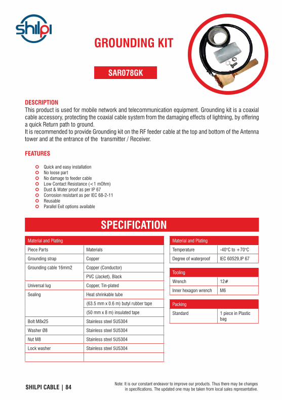
SHILPI CABLE | 84Note: It is our constant endeavor to improve our products. Thus there may be changes
in specifications. The updated one may be taken from local sales representative.
GROUNDING KIT
SAR078GK
DESCRIPTIONThis product is used for mobile network and telecommunication equipment. Grounding kit is a coaxial cable accessory, protecting the coaxial cable system from the damaging effects of lightning, by offering a quick Return path to ground.It is recommended to provide Grounding kit on the RF feeder cable at the top and bottom of the Antenna tower and at the entrance of the transmitter / Receiver.
FEATURES
Quick and easy installation No loose part No damage to feeder cable Low Contact Resistance (<1 mOhm) Dust & Water proof as per IP 67 Corrosion resistant as per IEC 68-2-11 Reusable Parallel Exit options available
SPECIFICATIONMaterial and Plating
Piece Parts Materials
Grounding strap Copper
Grounding cable 16mm2 Copper (Conductor)
PVC (Jacket), Black
Universal lug Copper, Tin-plated
Sealing Heat shrinkable tube
(63.5 mm x 0.6 m) butyl rubber tape
(50 mm x 8 m) insulated tape
Bolt M8x25 Stainless steel 5U5304
Washer Ø8 Stainless steel 5U5304
Nut M8 Stainless steel 5U5304
Lock washer Stainless steel 5U5304
Material and Plating
Temperature -40°C to +70°C
Degree of waterproof IEC 60529,IP 67
Tooling
Wrench 12#
Inner hexagon wrench M6
Packing
Standard 1 piece in Plastic bag
72 | SHILPI CABLE
GROUNDING KIT
SAR078GK SARN66CT
Description Value
Cable Tie Length: 100/200/300/400 mm
Body Material Nylon 6.6
Cable Tie Colour Black /White
Tensile Strength N/m²: 535N/mm²
Cable Tie Width 2.5/3.6/4.8/7.6mm
Cable Bundle Diameter Min 1.5/3.0mm
Cable Bundle Diameter Max 22/50/85/100/110mm
Accessory Type Cable Tie
Cable Diameter Max 75mm
Cable Diameter Min: 5mm
Description Value
External Length / Height 100/200/300/400 mm
External Width 2.5/3.6/4.8/4.6/7.6mm
Flammability Rating UL94V-2
Standard: US mil Spec 23190
/TQM gwrD
Tensile Strength (kg): 54.4kg
Tensile Strength N/mm²: 535N/mm²
Package Content 100
DescriptionAvailable in a wide range of materials, these cable ties all feature internal serrations allowing for a positive hold onto cable and pipe bundles. The design of the head guarantees a high tensile strength whilst allowing a very low insertion force, this, combined with the bent tail design of many of the ties ensures a simple and quick installation. Whilst easily installed by hand, - manual and pneumatic (for high volume applications) tensioning tools are available to ensure consistency of installation.
Application Method Quick, simple fixing by hand or with tensioning tools
Characteristics
Features Non Releasible ties once locked can not be opened or reduced Self Locking and one piece construction which ensures the fast and easy installation
L Length mm W Width mm T Thickness mm Length (Inch) TypeTensile Strength
Kg(lbs) Std. Qty/Bag
104 2.5 1.06 4 Miniature 8(18) 100/1000
153 3.6 1.25 6 Intermediate 18(40) 100
204 3.6/4.6 1.29 8 Standard 22(50) 100
254 4.8 1.43 10 Standard 22(50) 100
306 4.6/4.8 1.56 12.4 Standard 22(50) 100
380/400 4.8/7.6 1.78 15 Heavy Duty 55(120) 100
73 | SHILPI CABLE
NON-RELEASABLE CABLE TIE
SARN66CT
Description Value
Cable Tie Length: 100/200/300/400 mm
Body Material Nylon 6.6
Cable Tie Colour Black /White
Tensile Strength N/m²: 535N/mm²
Cable Tie Width 2.5/3.6/4.8/7.6mm
Cable Bundle Diameter Min 1.5/3.0mm
Cable Bundle Diameter Max 22/50/85/100/110mm
Accessory Type Cable Tie
Cable Diameter Max 75mm
Cable Diameter Min: 5mm
Description Value
External Length / Height 100/200/300/400 mm
External Width 2.5/3.6/4.8/4.6/7.6mm
Flammability Rating UL94V-2
Standard: US mil Spec 23190
/TQM gwrD
Tensile Strength (kg): 54.4kg
Tensile Strength N/mm²: 535N/mm²
Package Content 100
DescriptionAvailable in a wide range of materials, these cable ties all feature internal serrations allowing for a positive hold onto cable and pipe bundles. The design of the head guarantees a high tensile strength whilst allowing a very low insertion force, this, combined with the bent tail design of many of the ties ensures a simple and quick installation. Whilst easily installed by hand, - manual and pneumatic (for high volume applications) tensioning tools are available to ensure consistency of installation.
Application Method Quick, simple fixing by hand or with tensioning tools
Characteristics
Features Non Releasible ties once locked can not be opened or reduced Self Locking and one piece construction which ensures the fast and easy installation
L Length mm W Width mm T Thickness mm Length (Inch) TypeTensile Strength
Kg(lbs) Std. Qty/Bag
104 2.5 1.06 4 Miniature 8(18) 100/1000
153 3.6 1.25 6 Intermediate 18(40) 100
204 3.6/4.6 1.29 8 Standard 22(50) 100
254 4.8 1.43 10 Standard 22(50) 100
306 4.6/4.8 1.56 12.4 Standard 22(50) 100
380/400 4.8/7.6 1.78 15 Heavy Duty 55(120) 100
73 | SHILPI CABLE
NON-RELEASABLE CABLE TIE
DESCRIPTION

85 | SHILPI CABLE Note: It is our constant endeavor to improve our products. Thus there may be changes in specifications. The updated one may be taken from local sales representative.
GROUNDING KIT
SAR078GK
DESCRIPTIONThis product is used for mobile network and telecommunication equipment. Grounding kit is a coaxial cable accessory, protecting the coaxial cable system from the damaging effects of lightning, by offering a quick Return path to ground.It is recommended to provide Grounding kit on the RF feeder cable at the top and bottom of the Antenna tower and at the entrance of the transmitter / Receiver.
FEATURES
Quick and easy installation No loose part No damage to feeder cable Low Contact Resistance (<1 mOhm) Dust & Water proof as per IP 67 Corrosion resistant as per IEC 68-2-11 Reusable Parallel Exit options available
SPECIFICATIONMaterial and Plating
Piece Parts Materials
Grounding strap Copper
Grounding cable 16mm2 Copper (Conductor)
PVC (Jacket), Black
Universal lug Copper, Tin-plated
Sealing Heat shrinkable tube
(63.5 mm x 0.6 m) butyl rubber tape
(50 mm x 8 m) insulated tape
Bolt M8x25 Stainless steel 5U5304
Washer Ø8 Stainless steel 5U5304
Nut M8 Stainless steel 5U5304
Lock washer Stainless steel 5U5304
Material and Plating
Temperature -40°C to +70°C
Degree of waterproof IEC 60529,IP 67
Tooling
Wrench 12#
Inner hexagon wrench M6
Packing
Standard 1 piece in Plastic bag
72 | SHILPI CABLE
SARN66CTSARN66CT
Description Value
Cable Tie Length: 100/200/300/400 mm
Body Material Nylon 6.6
Cable Tie Colour Black /White
Tensile Strength N/m²: 535N/mm²
Cable Tie Width 2.5/3.6/4.8/7.6mm
Cable Bundle Diameter Min 1.5/3.0mm
Cable Bundle Diameter Max 22/50/85/100/110mm
Accessory Type Cable Tie
Cable Diameter Max 75mm
Cable Diameter Min: 5mm
Description Value
External Length / Height 100/200/300/400 mm
External Width 2.5/3.6/4.8/4.6/7.6mm
Flammability Rating UL94V-2
Standard: US mil Spec 23190
/TQM gwrD
Tensile Strength (kg): 54.4kg
Tensile Strength N/mm²: 535N/mm²
Package Content 100
DescriptionAvailable in a wide range of materials, these cable ties all feature internal serrations allowing for a positive hold onto cable and pipe bundles. The design of the head guarantees a high tensile strength whilst allowing a very low insertion force, this, combined with the bent tail design of many of the ties ensures a simple and quick installation. Whilst easily installed by hand, - manual and pneumatic (for high volume applications) tensioning tools are available to ensure consistency of installation.
Application Method Quick, simple fixing by hand or with tensioning tools
Characteristics
Features Non Releasible ties once locked can not be opened or reduced Self Locking and one piece construction which ensures the fast and easy installation
L Length mm W Width mm T Thickness mm Length (Inch) TypeTensile Strength
Kg(lbs) Std. Qty/Bag
104 2.5 1.06 4 Miniature 8(18) 100/1000
153 3.6 1.25 6 Intermediate 18(40) 100
204 3.6/4.6 1.29 8 Standard 22(50) 100
254 4.8 1.43 10 Standard 22(50) 100
306 4.6/4.8 1.56 12.4 Standard 22(50) 100
380/400 4.8/7.6 1.78 15 Heavy Duty 55(120) 100
73 | SHILPI CABLE
NON-RELEASABLE CABLE TIE
SARN66CT
Description Value
Cable Tie Length: 100/200/300/400 mm
Body Material Nylon 6.6
Cable Tie Colour Black /White
Tensile Strength N/m²: 535N/mm²
Cable Tie Width 2.5/3.6/4.8/7.6mm
Cable Bundle Diameter Min 1.5/3.0mm
Cable Bundle Diameter Max 22/50/85/100/110mm
Accessory Type Cable Tie
Cable Diameter Max 75mm
Cable Diameter Min: 5mm
Description Value
External Length / Height 100/200/300/400 mm
External Width 2.5/3.6/4.8/4.6/7.6mm
Flammability Rating UL94V-2
Standard: US mil Spec 23190
/TQM gwrD
Tensile Strength (kg): 54.4kg
Tensile Strength N/mm²: 535N/mm²
Package Content 100
DescriptionAvailable in a wide range of materials, these cable ties all feature internal serrations allowing for a positive hold onto cable and pipe bundles. The design of the head guarantees a high tensile strength whilst allowing a very low insertion force, this, combined with the bent tail design of many of the ties ensures a simple and quick installation. Whilst easily installed by hand, - manual and pneumatic (for high volume applications) tensioning tools are available to ensure consistency of installation.
Application Method Quick, simple fixing by hand or with tensioning tools
Characteristics
Features Non Releasible ties once locked can not be opened or reduced Self Locking and one piece construction which ensures the fast and easy installation
L Length mm W Width mm T Thickness mm Length (Inch) TypeTensile Strength
Kg(lbs) Std. Qty/Bag
104 2.5 1.06 4 Miniature 8(18) 100/1000
153 3.6 1.25 6 Intermediate 18(40) 100
204 3.6/4.6 1.29 8 Standard 22(50) 100
254 4.8 1.43 10 Standard 22(50) 100
306 4.6/4.8 1.56 12.4 Standard 22(50) 100
380/400 4.8/7.6 1.78 15 Heavy Duty 55(120) 100
73 | SHILPI CABLE
NON-RELEASABLE CABLE TIE
DESCRIPTION

SHILPI CABLE | 86Note: It is our constant endeavor to improve our products. Thus there may be changes
in specifications. The updated one may be taken from local sales representative.SHILPI CABLE | 86
PVC INSULATED BATTERY CABLESAn IS / ISO 9001 Company
65 | SHILPI CABLE
87 | SHILPI CABLE Note: It is our constant endeavor to improve our products. Thus there may be changes in specifications. The updated one may be taken from local sales representative.
PVC INSULATED BATTERY CABLESAn IS / ISO 9001 Company
65 | SHILPI CABLE87 | SHILPI CABLE
PVC Insulated Battery Cables aremanufactured from electrolytic grade, bright annealed,bunched,barecopperconductors.Thesecablesareinsulatedonstate-of-the-artextruderswithaspecialgradePVCcompound.ThisPVCisimpervioustowater,petrol,diesel,acids,engine&lubricatingoilsandgrease.Thesecablesareusedinapplicationswherebatteriesareused,e.g.,power,telecommunication,computers,etc.wheretheD.C.voltagedoesnotexceed100volts.Thesecablesarelong-lastingandensureproperdistributionofpowerinthevehicle.BatterycablesareusedbyOEMsinautomobilesegmenttoo.
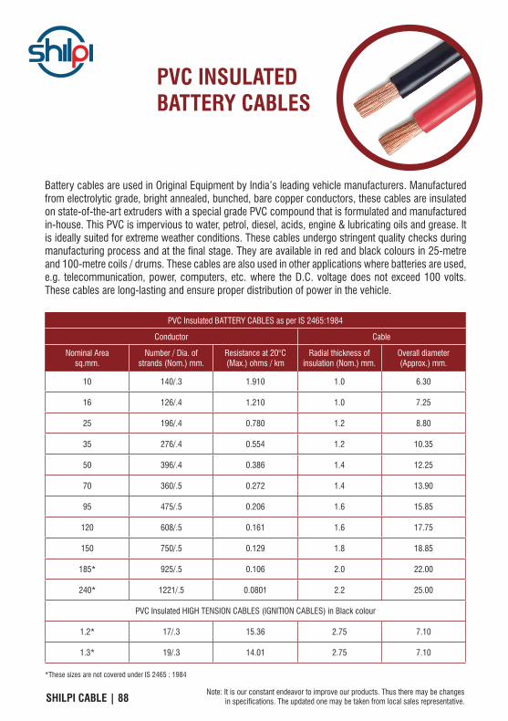
SHILPI CABLE | 88Note: It is our constant endeavor to improve our products. Thus there may be changes
in specifications. The updated one may be taken from local sales representative.SHILPI CABLE |
PVC INSULATED BATTERY CABLES
Battery cables are used in Original Equipment by India’s leading vehicle manufacturers. Manufactured from electrolytic grade, bright annealed, bunched, bare copper conductors, these cables are insulated on state-of-the-art extruders with a special grade PVC compound that is formulated and manufactured in-house. This PVC is impervious to water, petrol, diesel, acids, engine & lubricating oils and grease. It is ideally suited for extreme weather conditions. These cables undergo stringent quality checks during manufacturing process and at the final stage. They are available in red and black colours in 25-metre and 100-metre coils / drums. These cables are also used in other applications where batteries are used, e.g. telecommunication, power, computers, etc. where the D.C. voltage does not exceed 100 volts. These cables are long-lasting and ensure proper distribution of power in the vehicle.
PVC Insulated BATTERY CABLES as per IS 2465:1984
Conductor Cable
Nominal Areasq.mm.
Number / Dia. of strands (Nom.) mm.
Resistance at 20°C (Max.) ohms / km
Radial thickness of insulation (Nom.) mm.
Overall diameter (Approx.) mm.
10 140/.3 1.910 1.0 6.30
16 126/.4 1.210 1.0 7.25
25 196/.4 0.780 1.2 8.80
35 276/.4 0.554 1.2 10.35
50 396/.4 0.386 1.4 12.25
70 360/.5 0.272 1.4 13.90
95 475/.5 0.206 1.6 15.85
120 608/.5 0.161 1.6 17.75
150 750/.5 0.129 1.8 18.85
185* 925/.5 0.106 2.0 22.00
240* 1221/.5 0.0801 2.2 25.00
PVC Insulated HIGH TENSION CABLES (IGNITION CABLES) in Black colour
1.2* 17/.3 15.36 2.75 7.10
1.3* 19/.3 14.01 2.75 7.10
*These sizes are not covered under IS 2465 : 1984
66
PVC INSULATEDBATTERY CABLES
89 | SHILPI CABLE

SHILPI CABLE | 90Note: It is our constant endeavor to improve our products. Thus there may be changes
in specifications. The updated one may be taken from local sales representative.SHILPI CABLE | 90
91 | SHILPI CABLE Note: It is our constant endeavor to improve our products. Thus there may be changes in specifications. The updated one may be taken from local sales representative.
MOU/ROU/REPEATER
91 | SHILPI CABLE
RepeatersprovideuniformcoverageinTunnels,Highways,highrisebuildings,offices,shop-pingmalls,hospital,airports,Basementandcarparkingareas.
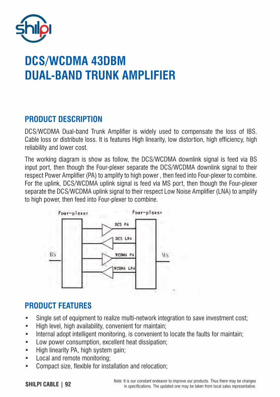
SHILPI CABLE | 92Note: It is our constant endeavor to improve our products. Thus there may be changes
in specifications. The updated one may be taken from local sales representative.
DCS/WCDMA 43DBMDUAL-BAND TRUNK AMPLIFIER
PRODUCT DESCRIPTIONDCS/WCDMA Dual-band Trunk Amplifier is widely used to compensate the loss of IBS.Cablelossordistributeloss.ItisfeaturesHighlinearity,lowdistortion,highefficiency,highreliability and lower cost.
Theworkingdiagram isshowas follow, theDCS/WCDMAdownlinksignal is feedviaBSinputport,thenthoughtheFour-plexerseparatetheDCS/WCDMAdownlinksignaltotheirrespectPowerAmplifier(PA)toamplifytohighpower,thenfeedintoFour-plexertocombine.Fortheuplink,DCS/WCDMAuplinksignalisfeedviaMSport,thenthoughtheFour-plexerseparatetheDCS/WCDMAuplinksignaltotheirrespectLowNoiseAmplifier(LNA)toamplifytohighpower,thenfeedintoFour-plexertocombine.
PRODUCT FEATURES• Singlesetofequipmenttorealizemulti-networkintegrationtosaveinvestmentcost;• Highlevel,highavailability,convenientformaintain;• Internaladoptintelligentmonitoring,isconvenienttolocatethefaultsformaintain;• Lowpowerconsumption,excellentheatdissipation;• HighlinearityPA,highsystemgain;• Localandremotemonitoring;• Compactsize,flexibleforinstallationandrelocation;

93 | SHILPI CABLE Note: It is our constant endeavor to improve our products. Thus there may be changes in specifications. The updated one may be taken from local sales representative.
SYSTEM CONNECTION DIAGRAM:
Electrical SpecificationsDownlink Uplink
1805-1880/2110-2170MHz 1710-1785/1920-1980MHz
OutputPower(Max.) 43±2dBmPerBand 0±3dBmPerBand
Gain(Max.) 45±3dB 45±3dB
MaxInputwithoutdamage +10dBm +10dBm
MaxInputRFlevel -25dBm -25dBm
MinInputRFlevel -107dBm -107dBm
NoiseFigure -- ≤5dB
GainAdjustableRange/Step ≥25dB/1dB
GainAdjustableError Gainadjustablerangeis0~20dB,error≤1dB;≥21dB,error≤1.5dB
Ripple ≤2dBinwithinthechannel
IMP3 ≤-45dBc(DCS) ≤-50dBc(DCS)
ALCWhenadding≤10dBatmax.Outputlevel,outputvariation≤±2dB,Whenadding>10dB,
outputvariation≤±2dBorbeoff.
VSWR ≤1.5
TimeDelay ≤1.0μs
Spurious Emission ComplieswithETSIEN300609-4
PowerSupply AC220V±60V,45~55Hz
Dimension **
Weight 0
Max.PowerConsumption 300W
OperatingTemperature -25~+550C
OperatingHumidity ≤95%
Environmental Class IP55
RFConnector N-Female,50ohm
MTBF ≥50000hours
MonitorInterface LocalMonitor:RemoteMonitor:RS232
AlarmType NoPower,PAFailure,VSWR,OverPower,OverTemperature
SHILPI CABLE | 94Note: It is our constant endeavor to improve our products. Thus there may be changes
in specifications. The updated one may be taken from local sales representative.
DCS&WCDMA 43DBMCABLE-ACCESS FIBER OPTIC REPEATER
PRODUCT DESCRIPTIONDCS/WCDMA Cable-access Fiber Optic Repeater is enlarge the signal of DCS/WCDMAequipment.TheMasterOpticalUnitSystemcapturestheBTSsignalofDCS/WCDMAandconvertsitintoopticsignalandtransmitstheamplifiedsignaltotheRemoteOpticalUnitviafiberopticcables.TheRemoteOpticalUnitwillreconverttheopticsignalintoDCS/WCDMAsignalandthenconverseDownlinkAmplifierandprovidethesignaltotheareaswherenetworkcoverageisinadequate.
And the mobile signal is also amplified and retransmitted to the BTS via the oppositedirection.ThedistributionsystembyourcompanyindependentresearchanddevelopmentiscomposedbyMasterOpticalUnitandRemoteOpticalUnit.Theinternalmoduleisintegrated,thehighlyintegratedtechnologyisimprovethestabilityoftheequipment.
PRODUCT FEATURES• Singlesetofequipmenttorealizemulti-networkintegrationtosaveinvestmentcost;• Highlevel,highavailability,convenientformaintain;• Internaladoptintelligentmonitoring,isconvenienttolocatethefaultsformaintain;• Lowpowerconsumption,excellentheatdissipation;• HighlinearityPA,highsystemgain;• Localandremotemonitoring;• Compactsize,flexibleforinstallationandrelocation;
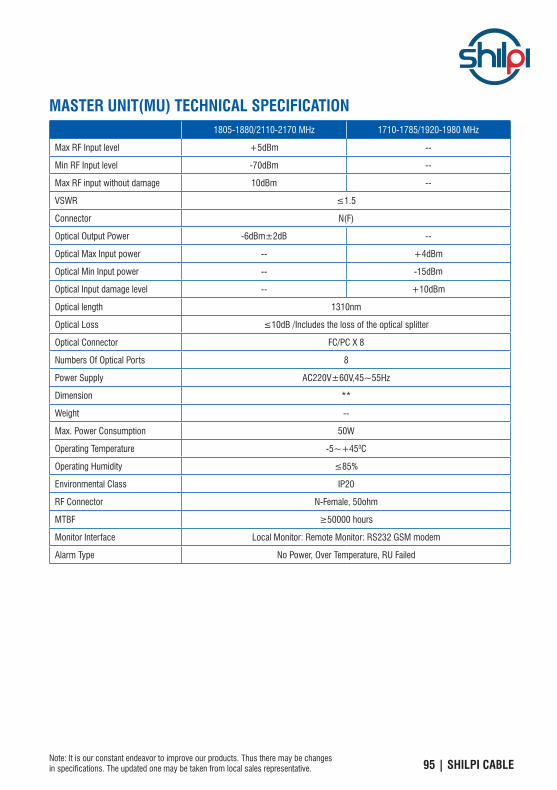
95 | SHILPI CABLE Note: It is our constant endeavor to improve our products. Thus there may be changes in specifications. The updated one may be taken from local sales representative.
MASTER UNIT(MU) TECHNICAL SPECIFICATION1805-1880/2110-2170MHz 1710-1785/1920-1980MHz
MaxRFInputlevel +5dBm --
MinRFInputlevel -70dBm --
MaxRFinputwithoutdamage 10dBm --
VSWR ≤1.5
Connector N(F)
OpticalOutputPower -6dBm±2dB --
OpticalMaxInputpower -- +4dBm
OpticalMinInputpower -- -15dBm
OpticalInputdamagelevel -- +10dBm
Opticallength 1310nm
OpticalLoss ≤10dB/Includesthelossoftheopticalsplitter
OpticalConnector FC/PCX8
NumbersOfOpticalPorts 8
PowerSupply AC220V±60V,45~55Hz
Dimension **
Weight --
Max.PowerConsumption 50W
OperatingTemperature -5~+450C
OperatingHumidity ≤85%
Environmental Class IP20
RFConnector N-Female,50ohm
MTBF ≥50000hours
MonitorInterface LocalMonitor:RemoteMonitor:RS232GSMmodem
AlarmType NoPower,OverTemperature,RUFailed

SHILPI CABLE | 96Note: It is our constant endeavor to improve our products. Thus there may be changes
in specifications. The updated one may be taken from local sales representative.
REMOTE UNIT(RU) TECHNICAL SPECIFICATIONElectrical Specifications
Downlink1805-1880/2110-2170MHz
Uplink1710-1785/1920-1980MHz
OutputPower(Max.) 43±2dBmPerBand -5±2dBmPerBand
Gain(Max.)(with0dBopticloss) 55±3dB 53±3dB
MaxInputwithoutdamage -- +10dBm
MaxInputRFlevel -- -25dBm
MinInputRFlevel -- -107dBm
NoiseFigure -- ≤5dB
GainAdjustableRange/Step ≥25dB/1dB
GainAdjustableError Gainadjustablerangeis0~20dB,error≤1dB;≥21dB,error≤1.5dB
Ripple ≤2dBinwithinthechannel
IMP3 ≤-45dBc(DCS) ≤-50dBc(DCS)
ALC Whenadding≤10dBatmax.Outputlevel,outputvariation≤±2dB,Whenadding>10dB,outputvariation≤±2dBorbeoff.
VSWR ≤1.5
TimeDelay ≤1.0μs
Spurious Emission ComplieswithETSIEN300609-4
OpticalOutputPower 0~3dBm
Opticallength 1310nm
OpticalLoss ≤10dB/Includesthelossoftheopticalsplitter
OpticalConnector FC/PC
OpticalMaxinputpower +4dBm
OpticalMininputpower -15dBm
Opticalinputpowerwithoutdamage +10dBm
PowerSupply AC220V±60V,45~55Hz
Dimension **
Weight -
Max.PowerConsumption 350W
OperatingTemperature -25~+550C
OperatingHumidity ≤95%
Environmental Class IP55
RFConnector N-Female,50ohm
MTBF ≥50000hours
MonitorInterface LocalMonitor:RemoteMonitor:RS232
AlarmType NoPower,PAFailure,VSWR,OverPower,OverTemperature

97 | SHILPI CABLE Note: It is our constant endeavor to improve our products. Thus there may be changes in specifications. The updated one may be taken from local sales representative.
DCS&WCDMA 43DBMCABLE-ACCESS FIBER OPTIC REPEATER
PRODUCT DESCRIPTIONDCS/WCDMA/LTECable-accessFiberOpticRepeaterisenlargethesignalofDCS/WCDMA/LTEequipment.TheMasterOpticalUnitSystemcapturestheBTSsignalofDCS/WCDMA/LTEandconvertsitintoopticsignalandtransmitstheamplifiedsignaltotheRemoteOpticalUnitviafiberopticcables.TheRemoteOpticalUnitwillreconverttheopticsignalintoDCS/WCDMA/LTEsignalandthenconverseDownlinkAmplifierandprovidethesignaltotheareaswherenetworkcoverageisinadequate.
And the mobile signal is also amplified and retransmitted to the BTS via the oppositedirection.ThedistributionsystembyourcompanyindependentresearchanddevelopmentiscomposedbyMasterOpticalUnitandRemoteOpticalUnit.Theinternalmoduleisintegrated,thehighlyintegratedtechnologyisimprovethestabilityoftheequipment.
PRODUCT FEATURES• Singlesetofequipmenttorealizemulti-networkintegrationtosaveinvestmentcost;• Highlevel,highavailability,convenientformaintain;• Internaladoptintelligentmonitoring,isconvenienttolocatethefaultsformaintain;• Lowpowerconsumption,excellentheatdissipation; • HighlinearityPA,highsystemgain;• Localandremotemonitoring;• Compactsize,flexibleforinstallationandrelocation;• Compactsize,flexibleforinstallationandrelocation;
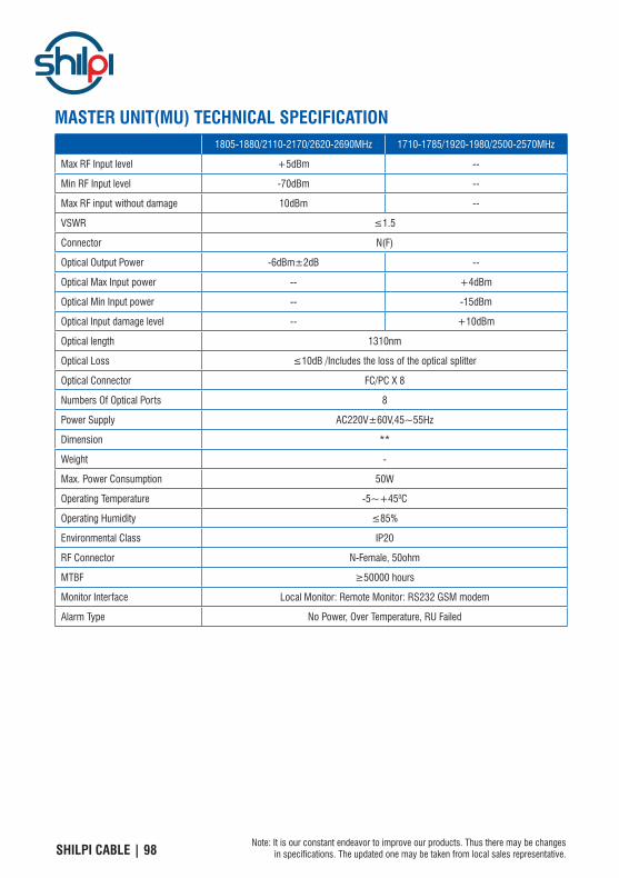
SHILPI CABLE | 98Note: It is our constant endeavor to improve our products. Thus there may be changes
in specifications. The updated one may be taken from local sales representative.
MASTER UNIT(MU) TECHNICAL SPECIFICATION1805-1880/2110-2170/2620-2690MHz 1710-1785/1920-1980/2500-2570MHz
MaxRFInputlevel +5dBm --
MinRFInputlevel -70dBm --
MaxRFinputwithoutdamage 10dBm --
VSWR ≤1.5
Connector N(F)
OpticalOutputPower -6dBm±2dB --
OpticalMaxInputpower -- +4dBm
OpticalMinInputpower -- -15dBm
OpticalInputdamagelevel -- +10dBm
Opticallength 1310nm
OpticalLoss ≤10dB/Includesthelossoftheopticalsplitter
OpticalConnector FC/PCX8
NumbersOfOpticalPorts 8
PowerSupply AC220V±60V,45~55Hz
Dimension **
Weight -
Max.PowerConsumption 50W
OperatingTemperature -5~+450C
OperatingHumidity ≤85%
Environmental Class IP20
RFConnector N-Female,50ohm
MTBF ≥50000hours
MonitorInterface LocalMonitor:RemoteMonitor:RS232GSMmodem
AlarmType NoPower,OverTemperature,RUFailed
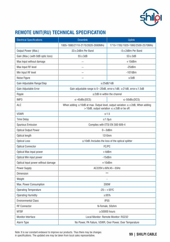
99 | SHILPI CABLE Note: It is our constant endeavor to improve our products. Thus there may be changes in specifications. The updated one may be taken from local sales representative.
REMOTE UNIT(RU) TECHNICAL SPECIFICATIONElectrical Specifications Downlink Uplink
1805-1880/2110-2170/2620-2690MHz 1710-1785/1920-1980/2500-2570MHz
OutputPower(Max.) 33±2dBmPerBand -5±2dBmPerBand
Gain(Max.)(with0dBopticloss) 55±3dB 53±3dB
MaxInputwithoutdamage -- +10dBm
MaxInputRFlevel -- -25dBm
MinInputRFlevel -- -107dBm
NoiseFigure -- ≤5dB
GainAdjustableRange/Step ≥25dB/1dB
GainAdjustableError Gainadjustablerangeis0~20dB,error≤1dB;≥21dB,error≤1.5dB
Ripple ≤2dBinwithinthechannel
IMP3 ≤-45dBc(DCS) ≤-50dBc(DCS)
ALC Whenadding≤10dBatmax.Outputlevel,outputvariation≤±2dB,Whenadding>10dB,outputvariation≤±2dBorbeoff.
VSWR ≤1.5
TimeDelay ≤1.0μs
Spurious Emission ComplieswithETSIEN300609-4
OpticalOutputPower 0~3dBm
Opticallength 1310nm
OpticalLoss ≤10dB/Includesthelossoftheopticalsplitter
OpticalConnector FC/PC
OpticalMaxinputpower +4dBm
OpticalMininputpower -15dBm
Opticalinputpowerwithoutdamage +10dBm
PowerSupply AC220V±60V,45~55Hz
Dimension **
Weight -
Max.PowerConsumption 200W
OperatingTemperature -25~+550C
OperatingHumidity ≤95%
Environmental Class IP55
RFConnector N-Female,50ohm
MTBF ≥50000hours
MonitorInterface LocalMonitor:RemoteMonitor:RS232
AlarmType NoPower,PAFailure,VSWR,OverPower,OverTemperature
SHILPI CABLE | 100Note: It is our constant endeavor to improve our products. Thus there may be changes
in specifications. The updated one may be taken from local sales representative.
GSM/DCS/WCDMA 46DBMCABLE-ACCESS FIBER OPTIC REPEATER DATA SHEET
PRODUCT DESCRIPTION
GSM/DCS/WCDMACable-accessFiberOpticRepeater isenlarge thesignalofGSM/DCS/WCDMAequipment.TheMasterOpticalUnitSystemcapturestheBTSsignalofGSM/DCS/WCDMAandconvertsitintoopticsignalandtransmitstheamplifiedsignaltotheRemoteOpticalUnitviafiberopticcables.TheRemoteOpticalUnitwillreconverttheopticsignalintoGSM/DCS/WCDMAsignalandthenconverseDownlinkAmplifierandprovidethesignaltotheareaswherenetworkcoverageisinadequate.
And the mobile signal is also amplified and retransmitted to the BTS via the oppositedirection.ThedistributionsystembyourcompanyindependentresearchanddevelopmentiscomposedbyMasterOpticalUnitandRemoteOpticalUnit.Theinternalmoduleisintegrated,thehighlyintegratedtechnologyisimprovethestabilityoftheequipment.
PRODUCT FEATURES• Singlesetofequipmenttorealizemulti-networkintegrationtosaveinvestmentcost;• Highlevel,highavailability,convenientformaintain;• Internaladoptintelligentmonitoring,isconvenienttolocatethefaultsformaintain;• Lowpowerconsumption,excellentheatdissipation;• HighlinearityPA,highsystemgain;• Localandremotemonitoring;• Compactsize,flexibleforinstallationandrelocation

101 | SHILPI CABLE Note: It is our constant endeavor to improve our products. Thus there may be changes in specifications. The updated one may be taken from local sales representative.
MASTER UNIT(MU) TECHNICAL SPECIFICATION935-960/1825-1865/2110-2145MHz 890-915/1730-1770/1920-1955MHz
MaxRFInputlevel +5dBm --
MinRFInputlevel -70dBm --
MaxRFinputwithoutdamage 10dBm --
VSWR ≤1.5
Connector N(F)
OpticalOutputPower -6dBm±2dB --
OpticalMaxInputpower -- +4dBm
OpticalMinInputpower -- -15dBm
OpticalInputdamagelevel -- +10dBm
Opticallength 1310nm
OpticalLoss ≤10dB/Includesthelossoftheopticalsplitter
OpticalConnector FC/PC
NumbersOfOpticalPorts 1
PowerSupply AC220V±60V,45~55Hz
Dimension **
Weight -
Max.PowerConsumption 50W
OperatingTemperature -5~+450C
OperatingHumidity ≤85%
Environmental Class IP20
RFConnector N-Female,50ohm
MTBF ≥50000hours
MonitorInterface LocalMonitor:RemoteMonitor:RS232GSMmodem
AlarmType NoPower,OverTemperature,RUFailed

SHILPI CABLE | 102Note: It is our constant endeavor to improve our products. Thus there may be changes
in specifications. The updated one may be taken from local sales representative.
REMOTE UNIT(RU) TECHNICAL SPECIFICATIONElectrical Specifications Downlink Uplink
935-960/1825-1865/2110-2145MHz 890-915/1730-1770/1920-1955MHz
OutputPower(Max.) 46±2dBmPerBand -5±2dBmPerBand
Gain(Max.)(with0dBopticloss) 55±3dB 53±3dB
MaxInputwithoutdamage -- +10dBm
MaxInputRFlevel -- -25dBm
MinInputRFlevel -- -107dBm
NoiseFigure -- ≤5dB
GainAdjustableRange/Step ≥25dB/1dB
GainAdjustableError Gainadjustablerangeis0~20dB,error≤1dB;≥21dB,error≤1.5dB
Ripple ≤2dBinwithinthechannel
IMP3 ≤-45dBc(DCS) ≤-50dBc(DCS)
ALC Whenadding≤10dBatmax.Outputlevel,outputvariation≤±2dB,Whenadding>10dB,outputvariation≤±2dBorbeoff.
VSWR ≤1.5
TimeDelay ≤1.0μs
Spurious Emission ComplieswithETSIEN300609-4
OpticalOutputPower 0~3dBm
Opticallength 1310nm
OpticalLoss ≤10dB/Includesthelossoftheopticalsplitter
OpticalConnector FC/PC
OpticalMaxinputpower +4dBm
OpticalMininputpower -15dBm
Opticalinputpowerwithoutdamage +10dBm
PowerSupply AC220V±60V,45~55Hz
Dimension **
Weight -
Max.PowerConsumption 700W
OperatingTemperature -25~+550C
OperatingHumidity ≤95%
Environmental Class IP55
RFConnector N-Female,50ohm
MTBF ≥50000hours
MonitorInterface LocalMonitor:RemoteMonitor:RS232
AlarmType NoPower,PAFailure,VSWR,OverPower,OverTemperature
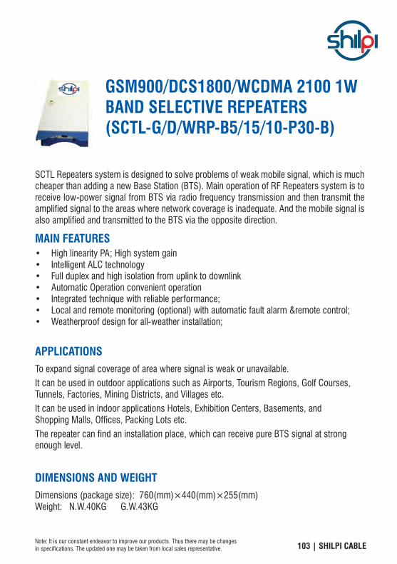
103 | SHILPI CABLE Note: It is our constant endeavor to improve our products. Thus there may be changes in specifications. The updated one may be taken from local sales representative.
GSM900/DCS1800/WCDMA 2100 1W BAND SELECTIVE REPEATERS(SCTL-G/D/WRP-B5/15/10-P30-B)
SCTLRepeaterssystemisdesignedtosolveproblemsofweakmobilesignal,whichismuchcheaperthanaddinganewBaseStation(BTS).MainoperationofRFRepeaterssystemistoreceivelow-powersignalfromBTSviaradiofrequencytransmissionandthentransmittheamplifiedsignaltotheareaswherenetworkcoverageisinadequate.AndthemobilesignalisalsoamplifiedandtransmittedtotheBTSviatheoppositedirection.
MAIN FEATURES• HighlinearityPA;Highsystemgain• IntelligentALCtechnology• Fullduplexandhighisolationfromuplinktodownlink• AutomaticOperationconvenientoperation• Integratedtechniquewithreliableperformance;• Localandremotemonitoring(optional)withautomaticfaultalarm&remotecontrol;• Weatherproofdesignforall-weatherinstallation;
APPLICATIONSToexpandsignalcoverageofareawheresignalisweakorunavailable.ItcanbeusedinoutdoorapplicationssuchasAirports,TourismRegions,GolfCourses,Tunnels,Factories,MiningDistricts,andVillagesetc.ItcanbeusedinindoorapplicationsHotels,ExhibitionCenters,Basements,andShoppingMalls,Offices,PackingLotsetc.Therepeatercanfindaninstallationplace,whichcanreceivepureBTSsignalatstrongenough level.
DIMENSIONS AND WEIGHTDimensions(packagesize):760(mm)×440(mm)×255(mm)Weight:N.W.40KGG.W.43KG

SHILPI CABLE | 104Note: It is our constant endeavor to improve our products. Thus there may be changes
in specifications. The updated one may be taken from local sales representative.
TECHNICAL SPECIFICATIONSDescription TestingCondition Specification
WorkingFrequency(MHz) NominalFrequency 910–915MHz 955-960MHz
1720-1735MHz
1815-1830MHz
1940–1950MHz
2130–2140MHz
Gain(dB) NominalOutputPower-5dB 100±3
OutputPower(dBm) WCDMAmodulatingsignal 30 30
ALC(dBm) InputSignaladd20dB Po≤±1
NoiseFigure(dB) Workingin-band(Max.Gain) ≤5
Ripplein-band(dB) NominalOutputPower-5dB ≤3
FrequencyTolerance(ppm) NominalOutputPower ≤0.05
TimeDelay(us) Workingin-band ≤5
EVM(%) Workingin-band ≤12.5
PCDE(dB) Workingin-band ≤35
GainAdjustmentStep(dB) NominalOutputPower-5dB 1dB
GainAdjustmentRange(dB) NominalOutputPower-5dB ≥30
GainAdjustableLinear(dB)
10dB NominalOutputPower-5dB ±1.0
20dB NominalOutputPower-5dB ±1.0
30dB NominalOutputPower-5dB ±1.5
Inter-modulationAttenuation(dBc)
(GSM/DCS) Workingin-band ≤-45
ACPR(dBc) ±5.0WCDMA Workingin-band ≤-45
±10.0WCDMA Workingin-band ≤-50
Spurious Emission(dBm)
9kHz-1GHz BW:30KHz ≤-36 ≤-36
1GHz-12.75GHz BW:30KHz ≤-30 ≤-30
VSWR BS/MSPort 1.5
I/OPort N-Female
Impedance 50ohm
OperatingTemperature -25°C~+55°C
RelativeHumidity Max.95%
MTBF Min.100000hours
PowerSupply DC-48V/AC220V(50Hz)/AC110V(60Hz)(±15%)
RemoteMonitoringFunction
Real-timealarmforDoorStatus,Temperature,PowerSupply,VSWR,OutputPower
RemoteControlModule RS232orRJ45+WirelessModem+ChargeableLi-ionBattery

105 | SHILPI CABLE Note: It is our constant endeavor to improve our products. Thus there may be changes in specifications. The updated one may be taken from local sales representative.
APPLICATION SCENARIOS
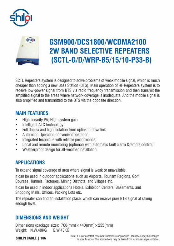
SHILPI CABLE | 106Note: It is our constant endeavor to improve our products. Thus there may be changes
in specifications. The updated one may be taken from local sales representative.
GSM900/DCS1800/WCDMA2100 2W BAND SELECTIVE REPEATERS (SCTL-G/D/WRP-B5/15/10-P33-B)
SCTLRepeaterssystemisdesignedtosolveproblemsofweakmobilesignal,whichismuchcheaperthanaddinganewBaseStation(BTS).MainoperationofRFRepeaterssystemistoreceivelow-powersignalfromBTSviaradiofrequencytransmissionandthentransmittheamplifiedsignaltotheareaswherenetworkcoverageisinadequate.AndthemobilesignalisalsoamplifiedandtransmittedtotheBTSviatheoppositedirection.
MAIN FEATURES• HighlinearityPA;Highsystemgain• IntelligentALCtechnology• Fullduplexandhighisolationfromuplinktodownlink• AutomaticOperationconvenientoperation• Integratedtechniquewithreliableperformance;• Localandremotemonitoring(optional)withautomaticfaultalarm&remotecontrol;• Weatherproofdesignforall-weatherinstallation;
APPLICATIONSToexpandsignalcoverageofareawheresignalisweakorunavailable.ItcanbeusedinoutdoorapplicationssuchasAirports,TourismRegions,Golf Courses,Tunnels,Factories,MiningDistricts,andVillagesetc.ItcanbeusedinindoorapplicationsHotels,ExhibitionCenters,Basements,andShoppingMalls,Offices,PackingLotsetc.Therepeatercanfindaninstallationplace,whichcanreceivepureBTSsignalatstrongenough level.
DIMENSIONS AND WEIGHTDimensions(packagesize):760(mm)×440(mm)×255(mm)Weight:N.W.40KGG.W.43KG
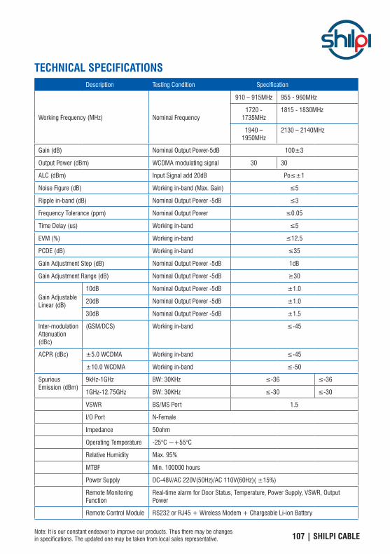
107 | SHILPI CABLE Note: It is our constant endeavor to improve our products. Thus there may be changes in specifications. The updated one may be taken from local sales representative.
TECHNICAL SPECIFICATIONSDescription TestingCondition Specification
WorkingFrequency(MHz) NominalFrequency
910–915MHz 955-960MHz
1720-1735MHz
1815-1830MHz
1940–1950MHz
2130–2140MHz
Gain(dB) NominalOutputPower-5dB 100±3
OutputPower(dBm) WCDMAmodulatingsignal 30 30
ALC(dBm) InputSignaladd20dB Po≤±1
NoiseFigure(dB) Workingin-band(Max.Gain) ≤5
Ripplein-band(dB) NominalOutputPower-5dB ≤3
FrequencyTolerance(ppm) NominalOutputPower ≤0.05
TimeDelay(us) Workingin-band ≤5
EVM(%) Workingin-band ≤12.5
PCDE(dB) Workingin-band ≤35
GainAdjustmentStep(dB) NominalOutputPower-5dB 1dB
GainAdjustmentRange(dB) NominalOutputPower-5dB ≥30
GainAdjustableLinear(dB)
10dB NominalOutputPower-5dB ±1.0
20dB NominalOutputPower-5dB ±1.0
30dB NominalOutputPower-5dB ±1.5
Inter-modulationAttenuation(dBc)
(GSM/DCS) Workingin-band ≤-45
ACPR(dBc) ±5.0WCDMA Workingin-band ≤-45
±10.0WCDMA Workingin-band ≤-50
Spurious Emission(dBm)
9kHz-1GHz BW:30KHz ≤-36 ≤-36
1GHz-12.75GHz BW:30KHz ≤-30 ≤-30
VSWR BS/MSPort 1.5
I/OPort N-Female
Impedance 50ohm
OperatingTemperature -25°C~+55°C
RelativeHumidity Max.95%
MTBF Min.100000hours
PowerSupply DC-48V/AC220V(50Hz)/AC110V(60Hz)(±15%)
RemoteMonitoringFunction
Real-timealarmforDoorStatus,Temperature,PowerSupply,VSWR,OutputPower
RemoteControlModule RS232orRJ45+WirelessModem+ChargeableLi-ionBattery

SHILPI CABLE | 108Note: It is our constant endeavor to improve our products. Thus there may be changes
in specifications. The updated one may be taken from local sales representative.SHILPI CABLE | 108
109 | SHILPI CABLE Note: It is our constant endeavor to improve our products. Thus there may be changes in specifications. The updated one may be taken from local sales representative.
OUTDOOR CABINET/ MINI SHELTER
109 | SHILPI CABLE
Helpsinprotectingandmovingvoice,videoanddataelectronicsclosertothesubscriber-fromoutdoorenclosuresforRadioBaseStations(RBS)andBaseTransceiverStations(BTS)or fiber pedestals and cabinets.

SHILPI CABLE | 110Note: It is our constant endeavor to improve our products. Thus there may be changes
in specifications. The updated one may be taken from local sales representative.
OUTDOOR CABINETS/MINI SHELTERS
PRODUCT DESCRIPTION1.1 Outdoor Enclosure (DC ACU + Monitoring Unit) The most efficient Outdoor Solution for Telco Equipment in the industry! IP55 UL Certified
ThecombinationofInnovationandcustomizeddesign,efficiencyandreliabilitymakestheShilpi’sOutdoorEnclosurestandout.Withlimitingthelossesintheformofheatdissipa-tionandnecessarycoolingrequirement,thelosseshavebeenreducedcomparedtothecurrent industry standard.
Inaglobalperspective,consideringthehighenergyconsumptioninthetelecomindustry,these Enclosures breakthrough is not only reducing operational cost for the operators, but it can also have a significant environmental impact.
a) KEY FEATURESBasicconfigurationiswith8powershelves.Standard.Ahighdegreeofflexibilitymakesiteasytomeetmostcustomerrequirementsfastandcostefficient.
DualSkinconstruction(Steel)2X4UBatteryShelves19UequipmentspaceThermalinsulationInclinedroofWith20 angleLiftingHooksontheupperSide4Nos.TelecomequipmentstorageDCAIRCONDITIONER+FAN/FILTERThermalmanagementIP55300AMPSpowersystemanddistributionRemotemanagement Easy installation Easy filter change Easy maintenanceHighestefficiencyinminimumspace
ResonanttopologymakesthemoduleefficiencyindustryleadingandcontributesSheltersultra-compactdimensions.
b) ApplicationsBroadband and network accessIncreasingnetworkdemandsstorageofCommunicationandPowercabinetswithcompactand less energy consumption solutions with flexibility and expandability. Shilpi Enclosures able to cascade as demand grows. Shilpi is delivering key building blocks for future needs.

111 | SHILPI CABLE Note: It is our constant endeavor to improve our products. Thus there may be changes in specifications. The updated one may be taken from local sales representative.
Small and largeDuetotheflexibilityandCustomizationinShilpi’sdesign,Shilpi’sSolutionisbecomecostcompetitive design and a highly flexible system for communication interface.
c) Technical Specification
Item TechnicalParameter
StorageTemp-warehousing
−400Cto+700 C
InnerDimensions 800mmX836mmX2147mm
OuterDimensions 916mmX960mmX2431mm
Weight 290kg,doorshallincludetemperaturecontrolequipment
Wind speed 50m/s
Solar radiation ≤1120W/m2
Altitude <4000m
AirPressure 70kPa~106kPa
Rustproof Saltspraytestforexposedparts≥240hours,referIEC60068-2-52
Fireproof ComplywithEN135001-1:2002B
Maintenance InfrontofMini-Shelter,Outdoor
LifeCycle 5yearsperformanceontechnicalground.Designlifevalidityis20years.
NoiseLevel ≤65db.(A)-GR487(soundpressurelevel)
WireLayout Leadin/outatthebottomofmini-shelter
Wall panel Wallmaterial-sandwichpanelwithheatinsulationmaterial.Thickness45mm-PU
Mini-ShelterStructure Assembled
d) Mechanical Specification
SHELTERTYPE AllWeatherProofBareMiniShelter-FactoryAssembled
EXTERNALSIZE 916mmX960mmX2431mm
INTERNALSIZE 800mmX836mmX2147mm
STEELBASEFRAMEGalvanizedISMB100x50asbasefoundationtohousetheshelterassemblywithlifting lugs.
INNERSEALINGANGLE Aluminumangle40mmx40mmx2mmshallbeprovided
EXTERNALSEALINGANGLE
MSPowdercoatedSealingAngle50mmx50mmx3mmisfixedallaroundtheshelter outside

SHILPI CABLE | 112Note: It is our constant endeavor to improve our products. Thus there may be changes
in specifications. The updated one may be taken from local sales representative.
MODULARWALLPANELSCladdingInnerPre-paintedGISheet.CladdingOuterPre-paintedGISheet.45mmthickPUFInsulationof45Kg/Cu.Mtrdensity.
FLOORPANELCladdingOuter0.5mmPre-paintedGISheet.45mmthickPUFInsulationof45Kg/Cu.Mtrdensity.DesignedFloorLoad500Kg/m2
ROOFPANEL
CladdingInner0.5mmPre-paintedGISheetCladdingOuter0.5mmPre-paintedGISheetFlatRoofwillbeprovidedDesignedRoofload100Kg/m2
PANELWATERTIGHTNESSSealantisappliedbetweenthepaneljointsinternally&externallytoprovidewatertightness after shelter assembly.
MAINDOOR
CladdingInner0.5mmPre-paintedGISheetCladdingOuter0.5mmPre-paintedGISheetDooropeningoutwards,hingedtotheleft.Aluminum/GIdoorSectionDoorlockStainlessSteelhinges(3Nos.)45mmthick,foaminsulateddoorwithsize900mmx2150mmwithEPDMrub-ber environmental gasket.
CUTOUTSWaveguidecablecutouts&ACcutoutstosuittherequirementdulysealedforwater tightness
DOORRAINGUARD Suitablerainguardontopofthedoorwillbeprovidedifrequired.
1.2. Air Conditioner /Monitoring System cum SMUa) Air ConditionerTheOCseriesoutdoorcabinetairconditionerisacoolingproductdevelopedforcabinet.Itisapplicableforthescenarioswhereinternalequipmentofthecabinetemitsalargequantityofheatandtheinternalequipmentissensitivefortemperatureandneedstobeisolatedfromtheoutdoorenvironmentcompletely.Theunithasperfect functions,suchaswithexternalfan controlled functions and features high reliability and easy installation, so that it can work oncethepowersupplyisavailableandnocomplexadjustmentisneeded.
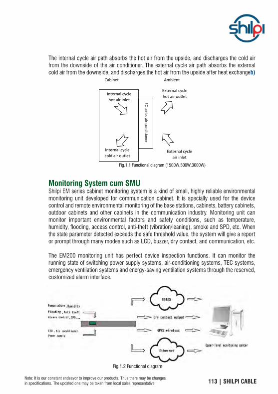
113 | SHILPI CABLE Note: It is our constant endeavor to improve our products. Thus there may be changes in specifications. The updated one may be taken from local sales representative.
Theinternalcycleairpathabsorbsthehotairfromtheupside,anddischargesthecoldairfromthedownsideof theairconditioner.Theexternalcycleairpathabsorbstheexternalcold air from the downside, and discharges the hot air from the upside after heat exchangeb)
Revision_5 OUTDOOR CABINETS/MINI SHELTERS 3
Cladding Outer 0.5mm Pre-painted GI Sheet Door opening outwards, hinged to the left. Aluminum / GI door Section Door lock Stainless Steel hinges (3 Nos.) 45mm thick, foam insulated door with size 900 mm x 2150 mm with EPDM rubber environmental gasket.
CUT OUTS Waveguide cable cutouts & AC cutouts to suit the requirement duly sealed for water tightness DOOR RAIN GUARD Suitable rain guard on top of the door will be provided if required.
1.2. Air Conditioner /Monitoring System cum SMU
a) Air Conditioner The OC series outdoor cabinet air conditioner is a cooling product developed for cabinet. It is applicable for the scenarios where internal equipment of the cabinet emits a large quantity of heat and the internal equipment is sensitive for temperature and needs to be isolated from the outdoor environment completely. The unit has perfect functions, such as with external fan controlled functions and features high reliability and easy installation, so that it can work once the power supply is available and no complex adjustment is needed.
The internal cycle air path absorbs the hot air from the upside, and discharges the cold air from the downside of the air conditioner. The external cycle air path absorbs the external cold air from the downside, and discharges the hot air from the upside after heat exchange
Fig.1.1 Functional diagram (1500W,500W,3000W)
EC series air conditioner
Internal cycle hot air inlet
Internal cycle cold air outlet
External cycle air inlet
External cycle hot air outlet
Cabinet Ambient
Monitoring System cum SMUShilpi EM series cabinet monitoring system is a kind of small, highly reliable environmental monitoring unit developed for communication cabinet. It is specially used for the devicecontrol and remote environmental monitoring of the base stations, cabinets, battery cabinets, outdoor cabinets and other cabinets in the communication industry. Monitoring unit can monitor important environmental factors and safety conditions, such as temperature, humidity,flooding,accesscontrol,anti-theft(vibration/leaning),smokeandSPD,etc.Whenthe state parameter detected exceeds the safe threshold value, the system will give a report orpromptthroughmanymodessuchasLCD,buzzer,drycontact,andcommunication,etc.
The EM200 monitoring unit has perfect device inspection functions. It can monitor therunningstateofswitchingpowersupplysystems,air-conditioningsystems,TECsystems,emergencyventilationsystemsandenergy-savingventilationsystemsthroughthereserved,customized alarm interface.
Revision_5 OUTDOOR CABINETS/MINI SHELTERS 4
b) Monitoring System cum SMU
Shilpi EM series cabinet monitoring system is a kind of small, highly reliable environmental monitoring unit developed for communication cabinet. It is specially used for the device control and remote environmental monitoring of the base stations, cabinets, battery cabinets, outdoor cabinets and other cabinets in the communication industry. Monitoring unit can monitor important environmental factors and safety conditions, such as temperature, humidity, flooding, access control, anti-theft (vibration/leaning), smoke and SPD, etc. When the state parameter detected exceeds the safe threshold value, the system will give a report or prompt through many modes such as LCD, buzzer, dry contact, and communication, etc. The EM200 monitoring unit has perfect device inspection functions. It can monitor the running state of switching power supply systems, air-conditioning systems, TEC systems, emergency ventilation systems and energy-saving ventilation systems through the reserved, customized alarm interface.
Fig.1.2 Functional diagram
i. Features 1U/19-inch standard rack mounting (mounted) mode, with 180mm depth. Full front cabling, helping save space, improve space utilization and facilitate mounting and maintenance. Configured with bilingual (Chinese and English) display man-machine interface, facilitating parameter checking and
setting on site. Real-time clock, facilitating current time setting and checking Equipped with operation status and alarm indicator lights and a buzzer (optional). Flexible power supply mode: DC or AC power supply. DC power supply range: 15~60VDC; AC power supply range:
100~240VAC (optional). The turning on/off of the LED light in the cabinet can be controlled according to the access status. Heat-exchanging fan control function: the fans are divided into two groups and are controlled automatically. The fan
can adjust speed according to the setting temperature, and the fan failure can be detected Heat-dissipating fan control: it can manage the heat-dissipating fans of three cabins. With RS485 communication interface for downstream equipment, it can connect to intelligent wattmeter, TEC air
conditioners (configured with TEC controllers) and other devices. It can communicate with the upstream equipment (including the main equipment) through the isolated RS485/RS422
communication interface Ethernet card is optional. With Ethernet card, the function of supporting protocols such as TCP/IP can be realized,
and you can monitor, maintain and manage the cabinet monitoring unit on any computer within the network. Wireless GPRS is optional. With wireless GPRS, the function of transmitting signals to the background or the upper-
level monitoring center through wireless mode in the far end can be realized. Note: If you need Ethernet, card or wireless GPRS, please note it on your purchasing order.

SHILPI CABLE | 114Note: It is our constant endeavor to improve our products. Thus there may be changes
in specifications. The updated one may be taken from local sales representative.
FEATURES1U/19-inchstandardrackmounting(mounted)mode,with180mmdepth.
Fullfrontcabling,helpingsavespace,improvespaceutilizationandfacilitatemounting and maintenance.
Configuredwithbilingual(ChineseandEnglish)displayman-machineinterface,facilitating parameter checking and setting on site.
Real-timeclock,facilitatingcurrenttimesettingandchecking
Equippedwithoperationstatusandalarmindicatorlightsandabuzzer(optional).
Flexiblepowersupplymode:DCorACpowersupply.DCpowersupplyrange:15~60VDC;AC powersupplyrange:100~240VAC(optional).
Theturningon/offoftheLEDlightinthecabinetcanbecontrolledaccordingtotheaccessstatus.
Heat-exchangingfancontrolfunction:thefansaredividedintotwogroupsandarecontrolled automatically.Thefancanadjustspeedaccordingtothesettingtemperature,andthefanfailure can be detected
Heat-dissipatingfancontrol:itcanmanagetheheat-dissipatingfansofthreecabins.
WithRS485communicationinterfacefordownstreamequipment,itcanconnecttointelligent wattmeter,TECairconditioners(configuredwithTECcontrollers)andotherdevices.
Itcancommunicatewiththeupstreamequipment(includingthemainequipment)throughthe isolatedRS485/RS422communicationinterface
Ethernetcardisoptional.WithEthernetcard,thefunctionofsupportingprotocolssuchasTCP/ IPcanberealized,andyoucanmonitor,maintainandmanagethecabinetmonitoringunitonany computer within the network.
Wireless GPRS is optional. With wireless GPRS, the function of transmitting signals to the background or the upperlevel monitoring center through wireless mode in the far end can be realized.
Note:IfyouneedEthernet,cardorwirelessGPRS,pleasenoteitonyourpurchasingorder.
Itcanoffer5VDCand12VDCoutputwithshort-circuitprotectionforexternalsensors,eliminating the need for additional power supply.
48VDCpowersupply,withanti-reverseprotectionandsoftstartfunctions.
1.3. DCDUTheDCDistributionUnitDCDU is toSupplyDCPowerdistribution for-48vDCequipment.Built-inoutputsurgemodule,canprovidepowersupplyforexternaldevices(differentialmode(8/20us):10kA:commonmode(8/20us):15kA))
1.4. BatteryTheAcmeTrangeoffrontaccessvalveregulatedleadacidbatterieshasbeenspecificallydesignedforapplicationsusing19”and23”cabinets,especiallytelecoms.Reliabilityisassuredwiththepatentedpost seal and a state-ofthe-art AGM design developed to comply with the latest IEC, British andTelcordiastandards.A12+yearsdesignlifeandcentralizedventingsystemaddtothesuitabilityandflexibility of this superior range.
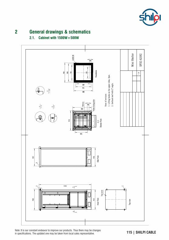
115 | SHILPI CABLE Note: It is our constant endeavor to improve our products. Thus there may be changes in specifications. The updated one may be taken from local sales representative.
2 General drawings & schematics 2.1. Cabinet with 1500W+500W
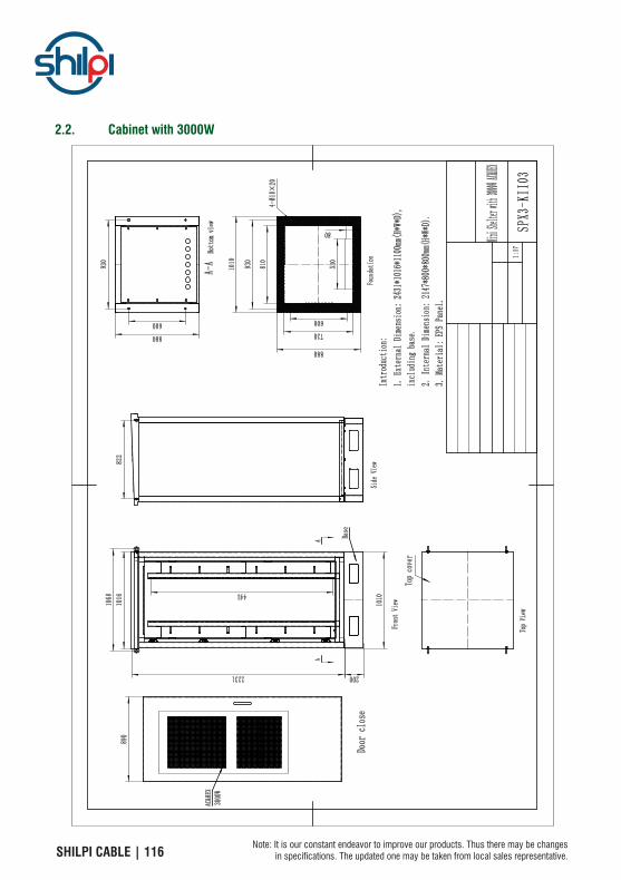
SHILPI CABLE | 116Note: It is our constant endeavor to improve our products. Thus there may be changes
in specifications. The updated one may be taken from local sales representative.
2.2. Cabinet with 3000W
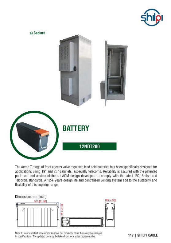
117 | SHILPI CABLE Note: It is our constant endeavor to improve our products. Thus there may be changes in specifications. The updated one may be taken from local sales representative.
BATTERY
12NDT200
TheAcmeTrangeoffrontaccessvalveregulatedleadacidbatterieshasbeenspecificallydesignedforapplicationsusing19”and23”cabinets,especiallytelecoms.Reliabilityisassuredwiththepatentedpost seal and a state-of-the-art AGM design developed to comply with the latest IEC, British andTelcordiastandards.A12+yearsdesignlifeandcentralisedventingsystemaddtothesuitabilityandflexibility of this superior range.
Dimensions-mm[inch]
5MIN 15MIN 30MIN 45MIN 1HR 2HR 3HR 4HR 5HR 6HR 8HR 10HR 12HR 20HR 24HR End voltage per cell
12NDT200
Dimensions-mm[inch]
Specifications
O OConstant Current Discharge Characteristics Units: Amperes (25 C, 77 F)
Container Material
Rated Capacity
Internal Resistance
Float Voltage
Nominal Voltage
Typical Weight
Equalize and Cycle Service
Self Discharge
Terminal
Recommended Maximum Charging Current Limit
Temperature Ranges
Terminal Hardware Torque
The residual capacity is above 90% after 90 days storage(25 /77 )O OC F
2.35V~2.40V/cell@25 (77 )O OC F
M6 Female
ABS (V0 optional)
2.25V/cell@25 (77 )O OC F
10 ± 1.0Nm
12V
200Ah (10 hour rate) to 1.80V/cell @25 (77 )O OC F
61.0 kg
Approx 3.50 mΩ
50 A
O ODischarge Data with Constant Power Units:Watts per cell (25 C, 77 F)
stored energy solutions for a demanding world
Model:
12NDT200Battery Model
Operation(maximum): -40 to 55 -40 to 131
Operation( recommended): 15 to 25 59 to 77 )
Storage: -20 to 40 -4 to 104
O O O OC C( F F)O O O OC C( F F
O O O OC C( F F)
The Acme T range of front access valve regulated lead acid batteries has been
specifically designed for applications using 19" and 23" cabinets, especially telecoms .
Reliability is assured with the patented post seal and a state-of-the-art AGM
design developed to comply with the latest IEC, British and Telcordia
standards. A 12+ years design life and centralised venting system
add to the suitability and flexibility of this superior range.
Copyright Narada Power Source Co.,Ltd. www.naradabattery.com
5MIN 15MIN 30MIN 45MIN 1HR 2HR 3HR 4HR 5HR 6HR 8HR 10HR 12HR 20HR 24HR End voltage per cell
558 [21.99]
31
6 [
12
.45
]
125 [4.93]
1.60V 967
642
411
330
281
166
118
1.67V 914 625
408
328
279
166
118
1.70V 881 613
406
327
278
165
117
1.60V 554.4
347.6
228.8
168.3
137.5
78.8
55.9
1.67V 519.2
342.1
225.5 168.3
136.4
78.1
55.6
1.70V 500.5 335.5 222.2 167.2 135.3 77.7 55.4
a) Cabinet
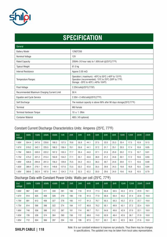
SHILPI CABLE | 118Note: It is our constant endeavor to improve our products. Thus there may be changes
in specifications. The updated one may be taken from local sales representative.
ConstantCurrentDischargeCharacteristicsUnits:Amperes(25OC,77OF)
End voltage
5MIN 15MN 30MN 45MN 1HR 2HR 3HR 4HR 5HR 6HR 8HR 10HR 12HR 20HR 24HR
1.60V 554.4 347.6 228.8 168.3 137.5 78.8 55.9 44.1 37.5 32.0 25.3 20.4 17.5 10.9 9.13
1.67V 519.2 342.1 225.5 168.3 136.4 78.1 55.6 44.1 37.2 31.7 25.1 20.3 17.4 10.8 9.05
1.70V 500.5 335.5 222.2 167.2 135.3 77.7 55.4 44.0 37.1 31.6 25.0 20.2 17.3 10.7 9.01
1.75V 475.2 321.2 213.4 163.9 134.2 77.1 55.1 43.8 36.9 31.2 24.8 20.1 17.2 10.6 8.93
1.80V 426.8 294.8 201.3 156.2 129.8 75.5 54.2 43.3 36.3 30.7 24.6 20.0 17.1 10.6 8.89
1.83V 389.4 276.1 191.4 149.6 127.6 73.5 53.2 42.8 35.5 29.9 24.3 19.8 16.9 10.5 8.84
1.85V 369.6 262.9 187.0 144.1 124.3 71.5 52.3 42.2 35.0 29.6 24.0 19.6 16.8 10.5 8.79
DischargeDatawithConstantPowerUnits:Wattspercell(25OC,77OF)End voltage
5MIN 15MN 30MN 45MN 1HR 2HR 3HR 4HR 5HR 6HR 8HR 10HR 12HR 20HR 24HR
1.60V 967 642 411 330 281 166 118 91.9 77.3 65.8 50.5 43.3 37.5 22.9 19.1
1.67V 914 625 408 328 279 166 118 91.5 77.0 65.6 50.4 43.2 37.4 22.8 19.0
1.70V 881 613 406 327 278 165 117 91.3 76.7 65.5 50.3 43.2 37.3 22.7 19.0
1.75V 814 590 398 322 274 164 117 90.8 76.2 65.1 49.9 43.1 37.2 22.4 18.9
1.80V 748 558 386 312 267 161 114 89.7 75.1 64.6 49.6 42.9 37.0 22.1 18.9
1.83V 726 528 374 304 260 156 112 88.6 74.0 63.9 48.4 42.6 36.7 21.9 18.8
1.85V 712 504 366 297 254 153 109 87.5 72.7 63.1 49.1 42.5 36.5 21.6 18.8
SPECIFICATIONGeneral
BatteryModel 12NDT200
NominalVoltage 12V
RatedCapacity 200Ah(10hourrate)to1.80V/cell@25OC(77OF)
TypicalWeight 61.0kg
InternalResistance Approx3.50mΩ
TemperatureRangesOperation(maximum):-400Cto550C(-400Fto1310F)Operation(recommended):150Cto250C(590Fto770F)Storage:-200Cto400C(-400to1040F)
FloatVoltage 2.25V/cell@25OC(77OF)
RecommendedMaximumChargingCurrentLimit 50A
EqualizeandCycleService 2.35V~2.40V/cell@25OC(77OF)
SelfDischarge Theresidualcapacityisabove90%after90daysstorage(25OC/77OF)
Terminal M6Female
TerminalHardwareTorque 10±1.0Nm
Container Material ABS(V0optional)

119 | SHILPI CABLE Note: It is our constant endeavor to improve our products. Thus there may be changes in specifications. The updated one may be taken from local sales representative.
TerminalVoltage(V)vs.DischargeTime(25OC,77OF) BatteryVoltagevs.ChargeTime
12NDT200
stored energy solutions for a demanding world
Model:
O OTerminal Voltage(V) Vs. Discharge Time (25 C, 77 F)
Relationship of OCV Vs. State of Charge Capacity Retention Characteristic
1CA0.6CA
0.25CA
0.1CA0.05CA
Dis
ch
arg
e V
olt
ag
e(V
)
Min h
13.5
13.0
12.5
12.0
11.5
11.0
Remained Capacity(%)
OC
V (
V)
10 20 30 40 50 60 70 80 90 1000
Ca
pa
cit
y(%
)
Storage Time(month)
0 2 6 12 30 60 3 10 20
13
12
11
10
9
8
3 6 9 12 15 18 21 24 27
50
25
75
O O30 C(86 F) O O20 C(68 F)
O O40 C(104 F)
O O10 C(50 F)
100
Battery Voltage Vs Charge Time .
Charge Characteristic
Charge Capacity
Charge Voltage
100%Charge
50%Charge
Charge Current
Time(hour)
Constant Charge At 0.20CA-14.1V(25℃)(CA) (V)
Ch
arg
eC
ap
ac
ity
Ch
arg
eC
urr
en
t
Ch
arg
eV
olt
ag
e
(%)
0.20
0.10
0
20 0.05
60
40
0.15
100
80
0
14
120
13
12
11
0 2 4 6 8 10 12
12
ND
T2
00-
01-
EN
M
arc
h 2
01
0
.S
ub
ject
to r
ev
isio
n w
ith
ou
t p
rio
r n
oti
ce
Charge Voltage (V/Cell)
Cycle 25 2.40 2.35~2.40OC
Standby 25 2.25 2.23~2.27OC
Application Set Point
Allowable Range
Max. Charge Current
0.25C
Temperature
Charging Procedures
DischargeCurrent (A)
Final Discharge
Voltage V/Cell
1.80 1.70 1.55 1.30
0.2C≥ (A) 0.2C<(A)<0.5C 0.5C<(A)<1.0C (A)>1.0C
Discharge Current VS. Discharge Voltage
NARADA POWER SOURCE CO.,LTD.No.459 Wensan Road, Hangzhou, Zhejiang, P.R.ChinaTel:+86-571-28827013 Fax:+86-571-85126942 Website:www.naradabattery.com E-mail: [email protected]
NARADA ASIA PACIFIC PTE.LTD.65 Ubi Crescent Hola centre, SingaporeTel: +65-6848 1191 Fax: +65-6749 3498E-mail: [email protected]
#07-05 NARADA EUROPE (UK) LIMITEDSpectrum House, Dunstable Road, Redbourn, St. Albans, Herts AL3 7PRTel: +44 (0)845 371 7095 Fax:+44 (0)845 612 2031 E-mail: [email protected]
DischargeCurrentVS.DischargeVoltage
ChargingProcedures
ApplicationChargeVoltage(V/Cell)
Max. Charge CurrentTemperature SetPoint AllowableRange
Cycle 25OC 2.40 2.35~2.400.25C
Standby 25OC 2.25 2.23~2.27
FinalDischargeVoltageV/Cell
1.80 1.70 1.55 1.30
DischargeCurrent(A) 0.2C≥(A) 0.2C<(A)<0.5C 0.5C<(A)<1.0C (A)>1.0C
12NDT200
stored energy solutions for a demanding world
Model:
O OTerminal Voltage(V) Vs. Discharge Time (25 C, 77 F)
Relationship of OCV Vs. State of Charge Capacity Retention Characteristic
1CA0.6CA
0.25CA
0.1CA0.05CA
Dis
ch
arg
e V
olt
ag
e(V
)
Min h
13.5
13.0
12.5
12.0
11.5
11.0
Remained Capacity(%)
OC
V (
V)
10 20 30 40 50 60 70 80 90 1000
Ca
pa
cit
y(%
)
Storage Time(month)
0 2 6 12 30 60 3 10 20
13
12
11
10
9
8
3 6 9 12 15 18 21 24 27
50
25
75
O O30 C(86 F) O O20 C(68 F)
O O40 C(104 F)
O O10 C(50 F)
100
Battery Voltage Vs Charge Time .
Charge Characteristic
Charge Capacity
Charge Voltage
100%Charge
50%Charge
Charge Current
Time(hour)
Constant Charge At 0.20CA-14.1V(25℃)(CA) (V)
Ch
arg
eC
ap
ac
ity
Ch
arg
eC
urr
en
t
Ch
arg
eV
olt
ag
e
(%)
0.20
0.10
0
20 0.05
60
40
0.15
100
80
0
14
120
13
12
11
0 2 4 6 8 10 12
12
ND
T2
00-
01-
EN
M
arc
h 2
01
0
.S
ub
ject
to r
ev
isio
n w
ith
ou
t p
rio
r n
oti
ce
Charge Voltage (V/Cell)
Cycle 25 2.40 2.35~2.40OC
Standby 25 2.25 2.23~2.27OC
Application Set Point
Allowable Range
Max. Charge Current
0.25C
Temperature
Charging Procedures
DischargeCurrent (A)
Final Discharge
Voltage V/Cell
1.80 1.70 1.55 1.30
0.2C≥ (A) 0.2C<(A)<0.5C 0.5C<(A)<1.0C (A)>1.0C
Discharge Current VS. Discharge Voltage
NARADA POWER SOURCE CO.,LTD.No.459 Wensan Road, Hangzhou, Zhejiang, P.R.ChinaTel:+86-571-28827013 Fax:+86-571-85126942 Website:www.naradabattery.com E-mail: [email protected]
NARADA ASIA PACIFIC PTE.LTD.65 Ubi Crescent Hola centre, SingaporeTel: +65-6848 1191 Fax: +65-6749 3498E-mail: [email protected]
#07-05 NARADA EUROPE (UK) LIMITEDSpectrum House, Dunstable Road, Redbourn, St. Albans, Herts AL3 7PRTel: +44 (0)845 371 7095 Fax:+44 (0)845 612 2031 E-mail: [email protected]
RelationshipofOCVvs.StateofCharge CapacityRetentionCharacteristic

SHILPI CABLE | 120Note: It is our constant endeavor to improve our products. Thus there may be changes
in specifications. The updated one may be taken from local sales representative.
Dubai Office
Shilpi Worldwide JLTUnitNo.30-01-385,FloorNo.1BuildingNo.3,PlotNo.550-554J&GComplex,AlmasTowersDMCC,Dubai,UnitedArabEmirates.P.O.BoxNo.113248.PhoneNo.:+97142388340
Shilpi Cables Technologies LtdChinnaBelangondapalli, NagondapalliPost,Mathigiri-635110Hosur.Tamilnadu.
Factory
Shilpi Cables Technologies LtdA-19/B-1ExtensionMohanCo-op.IndustrialEstateMathuraRoad,P.O.BadarpurNewDelhi-110044,IndiaTel.:+911143117900Fax.:+911143117902
Corporate Office
SP-1037RIICOIndustrialArea,ChopankiBhiwadi,Dist.AlwarRajasthan-301019,India
CIN:L64201DL2006PLC150753


