
1
Phase 1 ModelFeatures:
Imported background Scale the drawing Multiple resources Multiple Routes Entity Name and Graphic Change Service times

2
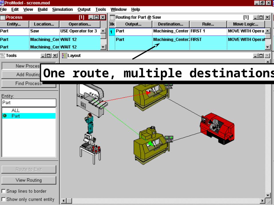
Multiple Routes
One Route with multiple destinations.
3
One route, multiple destinationsOne route, multiple destinations

4

5

6

7

8
Phase 2 ModelFeatures:
Attributes Resource & Location Downtimes Mathematical & User Distributions New Operation Statements Logs
9
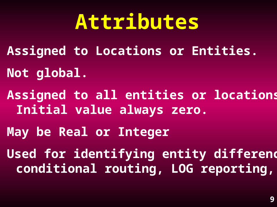
Attributes Assigned to Locations or Entities.
Not global.
Assigned to all entities or locations. Initial value always zero.
May be Real or Integer
Used for identifying entity differences, conditional routing, LOG reporting, ...
10
Attribute edit tableAttribute edit table

11
Location Downtimes
Four Types; Clock, Entry, Usage, Setup
Usage
• Records the total cumulative time the location is in operation
• Upon reaching the defined cumulative time, location goes down
• Downtime logic defines length of downtime and any action necessary

12
Location usage downtimeLocation usage downtime

13
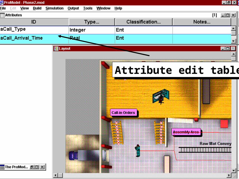
Resource Downtimes
Clock or Usage
Logic Field is the length of the downtime
May be Scheduled or Unscheduled
Preemptable
14
Resource clock downtimeResource clock downtime

15
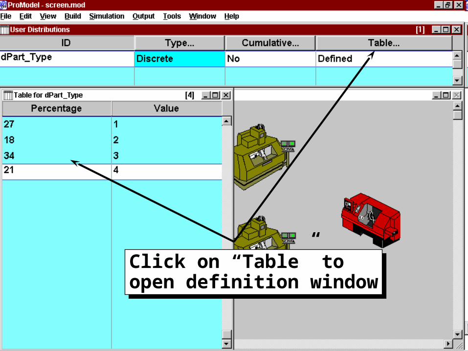
1. User defined Distribution tables may be created under the Build - More Elements menu.
2. Used to define user created distributions.
3. Sampled from by calling TABLE_NAME() in a logic field. This will assign the sampled value to an attribute or variable.
aType_of_Call = dCall_Dist()
User Distributions

16
17
Click on “Table” toopen definition windowClick on “Table” toopen definition window

18
Operation Statements Assignment ( i.e. = )
Not really a statement, just setting one itemequal to another
Syntax: vProcess_Time = N(3.2,.47)
DISPLAY
Pauses the simulation and displays a usercreated message
Syntax: DISPLAY <“string text message”>

19
Operation Statements CLOCK()
Returns the value of the system simulationclock. Used for a test or to store the value.
Syntax: aStart_Time = CLOCK()
ROUTE #
Defines which of the numbered routings you arereferring to in a logic statement
Syntax: If aPart_Type=1 then ROUTE 6
20
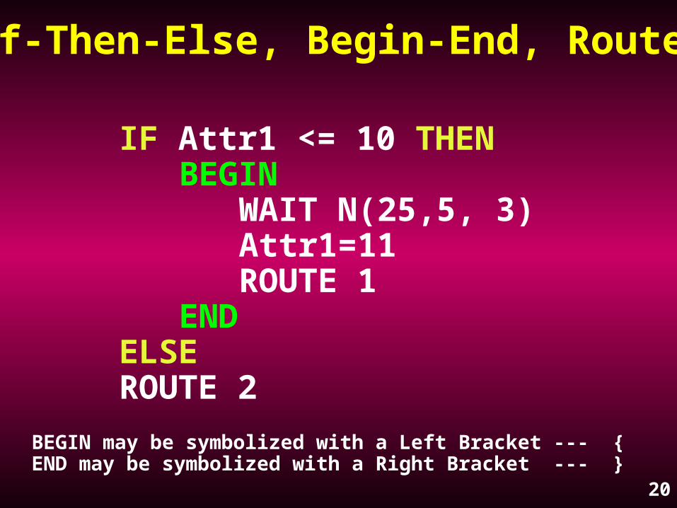
IF Attr1 <= 10 THENBEGIN
WAIT N(25,5, 3)Attr1=11ROUTE 1
ENDELSEROUTE 2
If-Then-Else, Begin-End, Route
BEGIN may be symbolized with a Left Bracket --- {END may be symbolized with a Right Bracket --- }
21
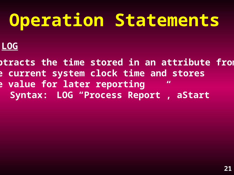
Operation Statements LOG
Subtracts the time stored in an attribute fromthe current system clock time and storesthe value for later reporting
Syntax: LOG “Process Report”, aStart

22

23

24

25
26
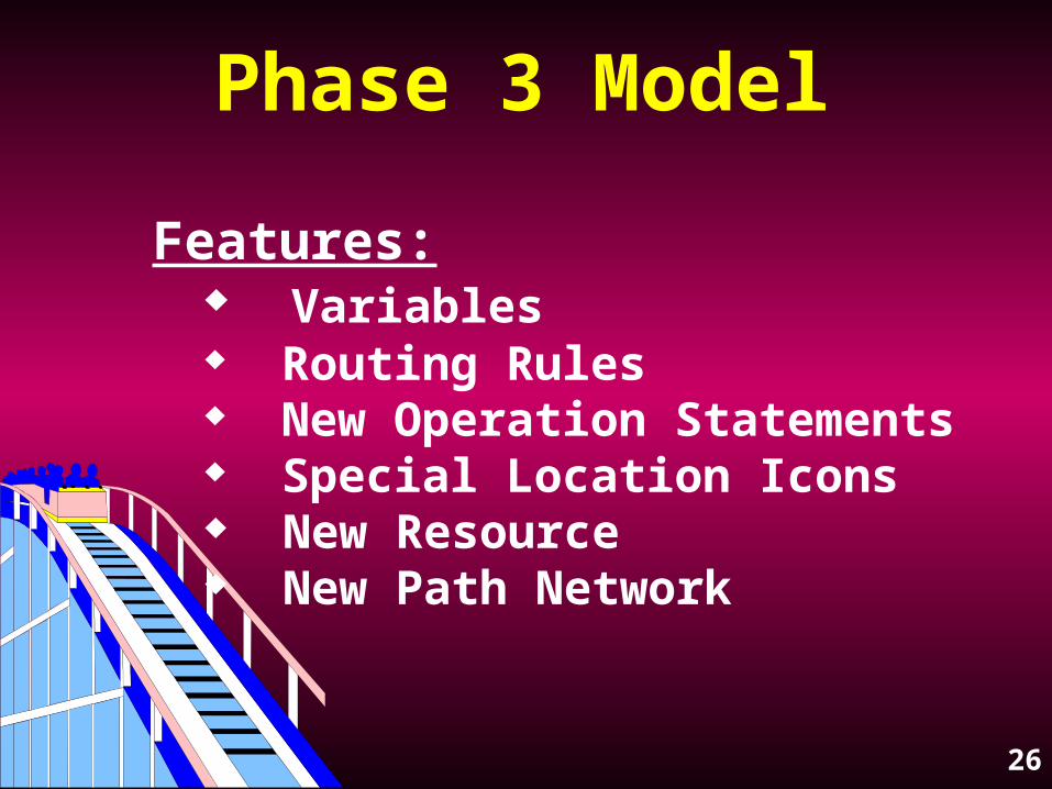
Phase 3 Model
Features: Variables Routing Rules New Operation Statements Special Location Icons New Resource New Path Network
27
Global Variables
Carry a numeric value Used for decision making or recording values May be INCremented, DECremented or assigned values As a global variable it may only have one value at a time Initial value is changeable May be displayed on the screen

28
Variable edit tableVariable edit table
Variablesdisplayedon thelayout
Variablesdisplayedon thelayout

29
Routing Rules UNTIL FULL
Fills the first destination listed until it iscapacitated, then the next one, etc.
Syntax: FULL <quantity expression>
PROBABILITY
Randomly selects a destination listed in a blockof routings based on a probability
Syntax: .43.57

30
Operation Statements INC
Increments or adds a value to a variable,attribute or array cell
Syntax: INC vCounter, <by how much>
DEC
Decrements or subtracts a value from a variable,attribute or array cell
Syntax: DEC vCounter, <by how much>

31
Operation Statements GROUP
Consolidates and accumulates a specifiednumber of entities into a single entity thathas a new name.
The new entity is named as the output entity.
Syntax: GROUP <numeric expression>
32
Operation Statements UNGROUP
Separates entities that were GROUPed usingthe GROUP statement.
After UNGROUPing, you must have a processdefined at the ungroup location for allentities that could be within the grouped entity.
There is NO routing entry AT ALL after anUNGROUP statement.
Syntax: UNGROUP

33
Operation Statements JOIN
Both a Routing Rule AND an Operation Statement.
As a Routing Rule: holds the entity at currentlocation until another entity at a different location calls for it with a JOIN Operation Statement.
As an Operation Statement: causes the waitingentity to be released.
Syntax: JOIN <how many><entity name>

34

35

36

37

38

39
Phase 4 Model
Features: Multiple Numbered Routes Shift Scheduling Static Resource New Operation Statements

40
Multiple Routes
Multiple numbered Routes with operation logic to determine which route to execute.

41
Multiple numbered routes,logic determines which toexecute
Multiple numbered routes,logic determines which toexecute
42
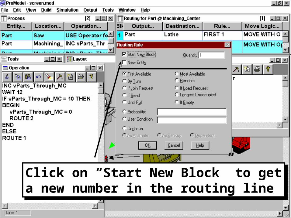
Click on “Start New Block” to geta new number in the routing lineClick on “Start New Block” to geta new number in the routing line

43
Shift Scheduling
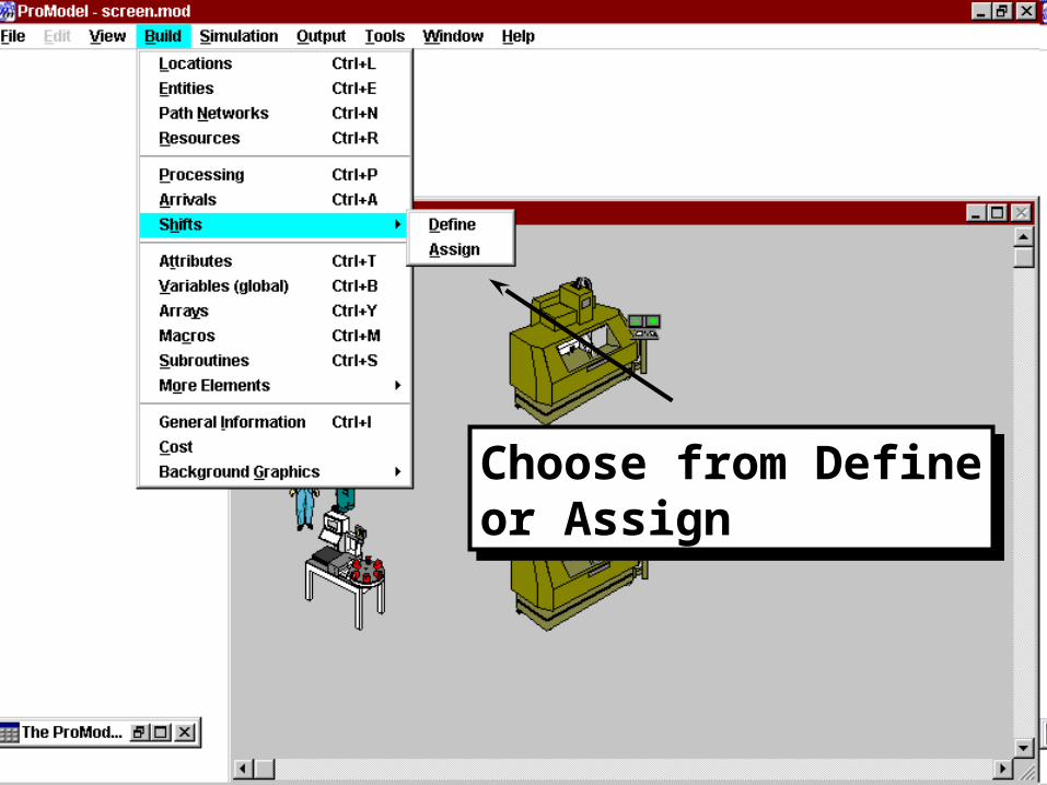
Define shifts from the BUILD - SHIFTS - DEFINE menu.
Shift and Break periods may be defined in 1 minute increments.
Save the created shift with a file name.
Assign Resources and Locations to the shift from the BUILD - SHIFTS - ASSIGN menu.

44
Shift Scheduling
Different priorities for starting a break or an off shift may be defined. Different priorities for while on break or on shift may also be defined.
Logic may be applied to break and offshift periods as well as pre-break and pre-offshift periods.
45
Choose from Defineor AssignChoose from Defineor Assign

46
Note ability to modify shiftNote ability to modify shift

47
Several locations and resourcesmay be assigned to the sameshift. Resources within a singlegroup (e.g. 5 repairman) may beassigned to different shifts.
Several locations and resourcesmay be assigned to the sameshift. Resources within a singlegroup (e.g. 5 repairman) may beassigned to different shifts.
Priorities for ending shift,off shift, starting breakand break.
Priorities for ending shift,off shift, starting breakand break.
Logic for pre-off shift,off shift, pre-break andbreak is entered here.
Logic for pre-off shift,off shift, pre-break andbreak is entered here.
48
Static Resources
Used for immobile resources
Do not require assignment to a path network
Place the graphic directly on the layout where you want the resource Changes color to show status
49
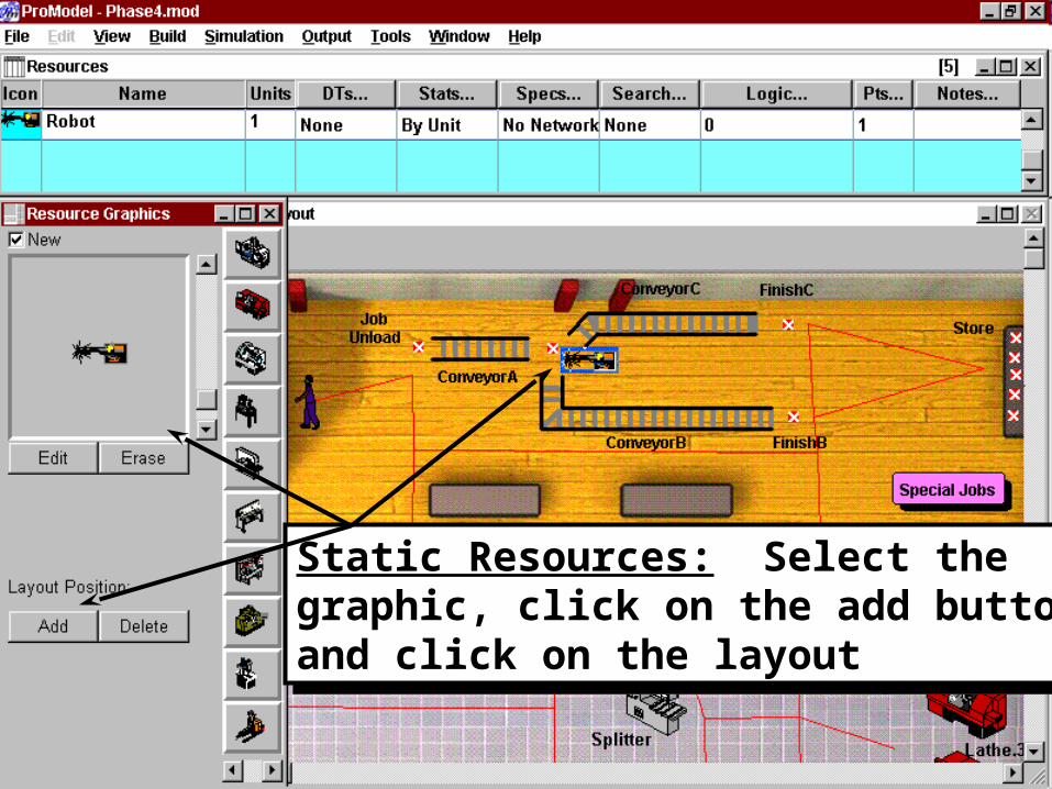
Static Resources: Select thegraphic, click on the add buttonand click on the layout
Static Resources: Select thegraphic, click on the add buttonand click on the layout

50
Routing Path Movement
Entities may be moved on Routing Paths (process arrows)
They may only move for a time expression - use the MOVE FOR statement in Move Logic
Routing paths may be bent by adding joints with a right click

51
Example of a bent routing path. Pathsare automatically drawn when the processis defined. Bend them by adding a jointafter right clicking on the path. Entities,but not resources, may move on the path
Example of a bent routing path. Pathsare automatically drawn when the processis defined. Bend them by adding a jointafter right clicking on the path. Entities,but not resources, may move on the path

52
Setting Run Duration
Simulation run duration is set in the SIMULATION - OPTIONS menu
You may choose Time, Weekly or Calendar Date
The next example shows setting the run time with a calendar date
53
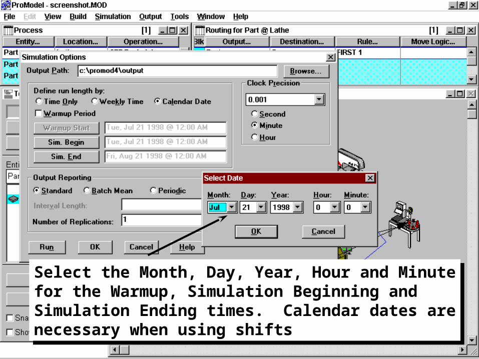
Select the Month, Day, Year, Hour and Minutefor the Warmup, Simulation Beginning andSimulation Ending times. Calendar dates arenecessary when using shifts
Select the Month, Day, Year, Hour and Minutefor the Warmup, Simulation Beginning andSimulation Ending times. Calendar dates arenecessary when using shifts

54
Operation Statements LOAD
Both a Routing Rule AND an Operation Statement.
As a Routing Rule: holds the entity at currentlocation until another entity at a different location calls for it with a LOAD Operation Statement.
As an Operation Statement: loads a specifiedquantity of entities onto the current entity.
Syntax: LOAD <how many>
55
Operation Statements UNLOAD
Unloads a certain quantity of entities.
If the numeric expression is larger than the number of loaded items, it will unload all items and ignore the difference.
Syntax: UNLOAD <how many> UNLOAD 5 IFF <boolean expression>

56

57

58

59

60
61
Phase 5 ModelFeatures:
Costing Stat::Fit Run Time Interface Scenarios Termination Logic New Operation Statements Multiple Replications
62
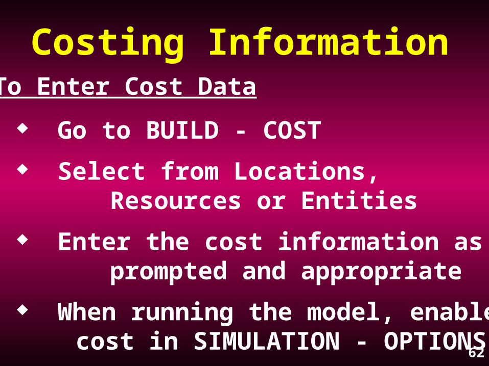
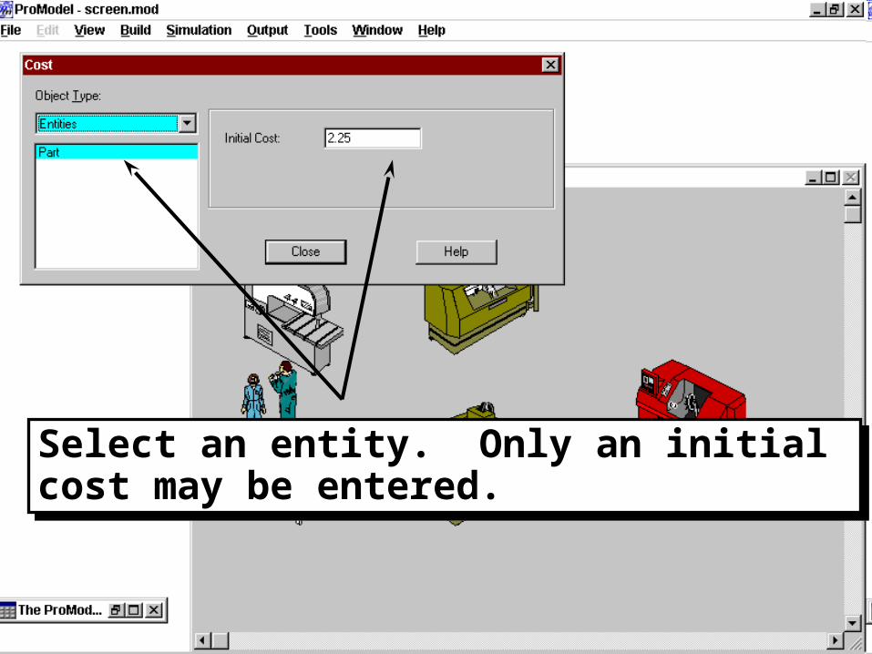
Costing InformationTo Enter Cost Data
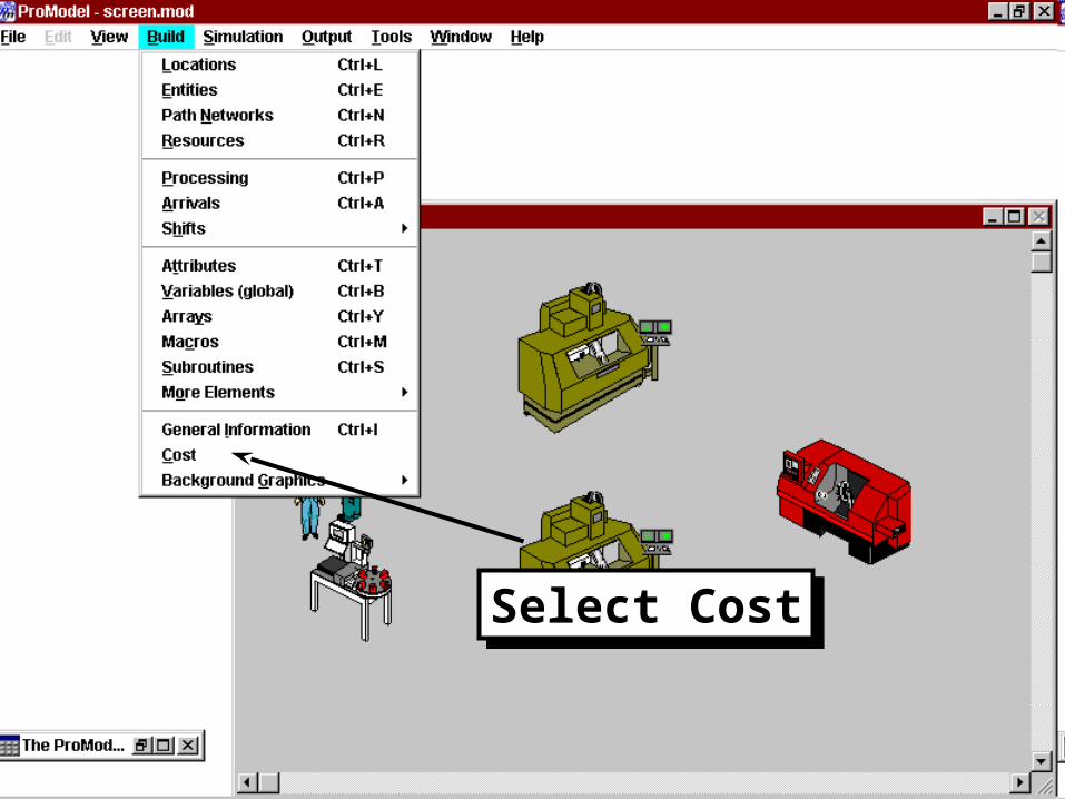
Go to BUILD - COST
Select from Locations, Resources or Entities
Enter the cost information as prompted and appropriate
When running the model, enable cost in SIMULATION - OPTIONS
63
Select CostSelect Cost
64
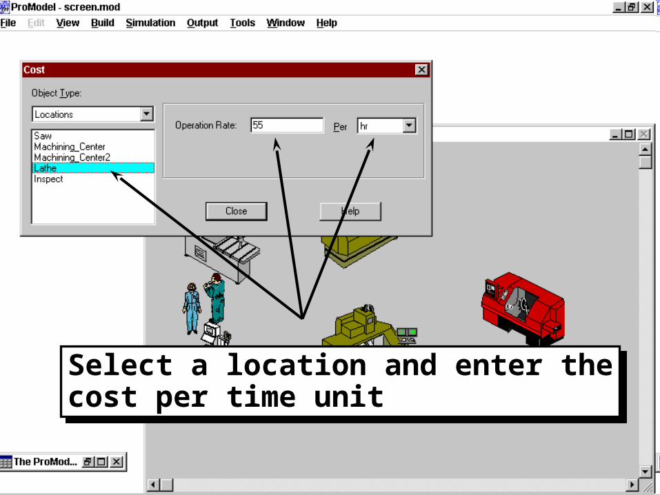
Select a location and enter thecost per time unitSelect a location and enter thecost per time unit

65
Select a resource and enter thecost per time unit and/or a costper use
Select a resource and enter thecost per time unit and/or a costper use
66
Select an entity. Only an initial cost may be entered.Select an entity. Only an initial cost may be entered.
67
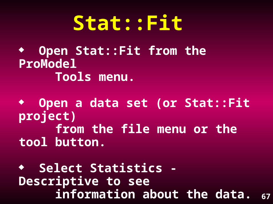
Stat::Fit Open Stat::Fit from the ProModel Tools menu.
Open a data set (or Stat::Fit project) from the file menu or the tool button.
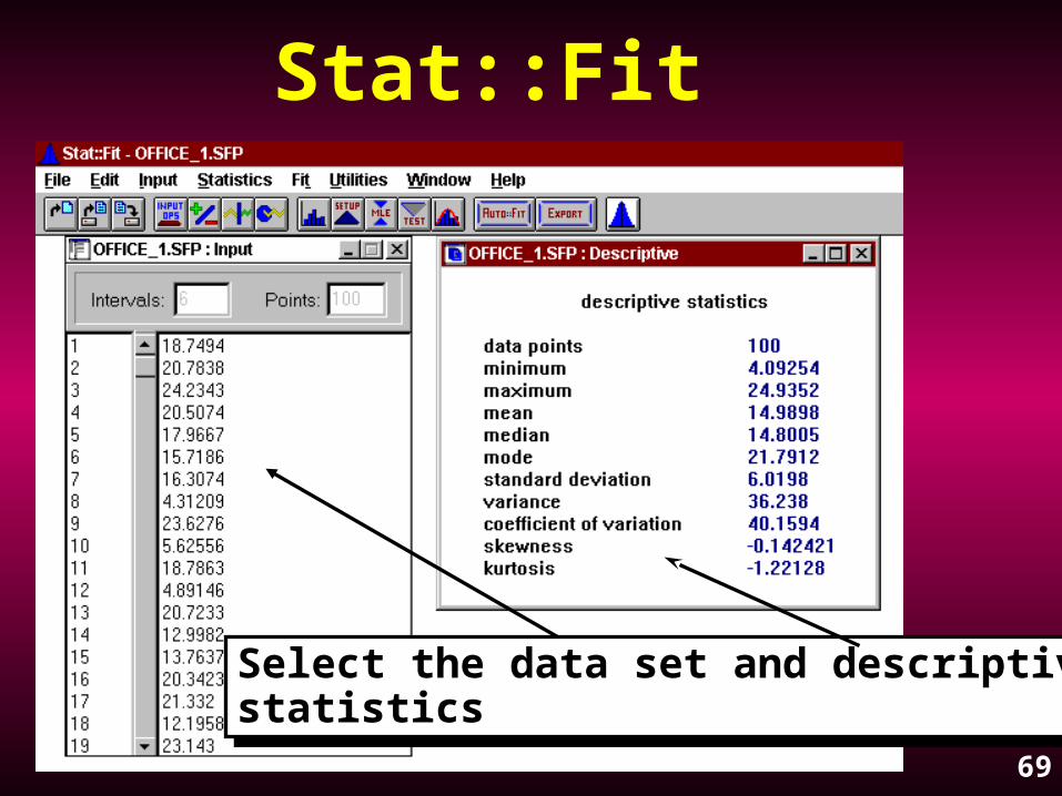
Select Statistics - Descriptive to see information about the data.
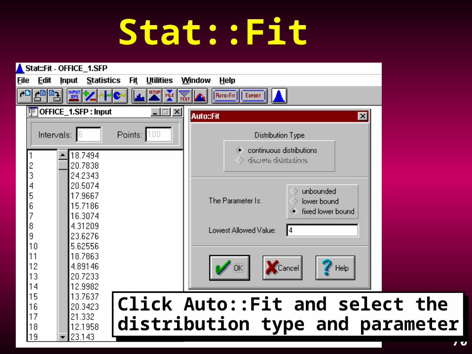
Click the Auto::Fit button and confirm the distribution type and parameter.

68
Stat::Fit Check the fit rankings and the null hypothesis accept or reject.
Select the distribution to view how well it fits.
Click the Export button, select which distribution and copy to clipboard.
Paste the distribution (in ProModel format) into the model.
69
Stat::Fit
Select the data set and descriptivestatisticsSelect the data set and descriptivestatistics
70
Stat::Fit
Click Auto::Fit and select the distribution type and parameterClick Auto::Fit and select the distribution type and parameter

71
Stat::Fit
Select an accepteddistribution andview how well itfits
Select an accepteddistribution andview how well itfits

72
Stat::Fit
Select thedistributionand copy theformat to theclipboard.
Then paste itto ProModel.
Select thedistributionand copy theformat to theclipboard.
Then paste itto ProModel.
73
Runtime Interface (RTI)
Easily change model parameters at the start of a model run.
Uses RTI macros.
Provides the ability to run multiple scenarios in a single batch.

74
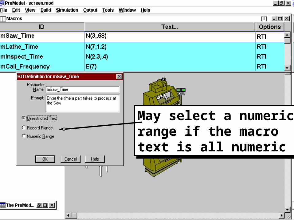
Macro nameMacro name RTI:Defined orNone
RTI:Defined orNone
Macro textMacro text
75
May select a numericrange if the macrotext is all numeric
May select a numericrange if the macrotext is all numeric
76
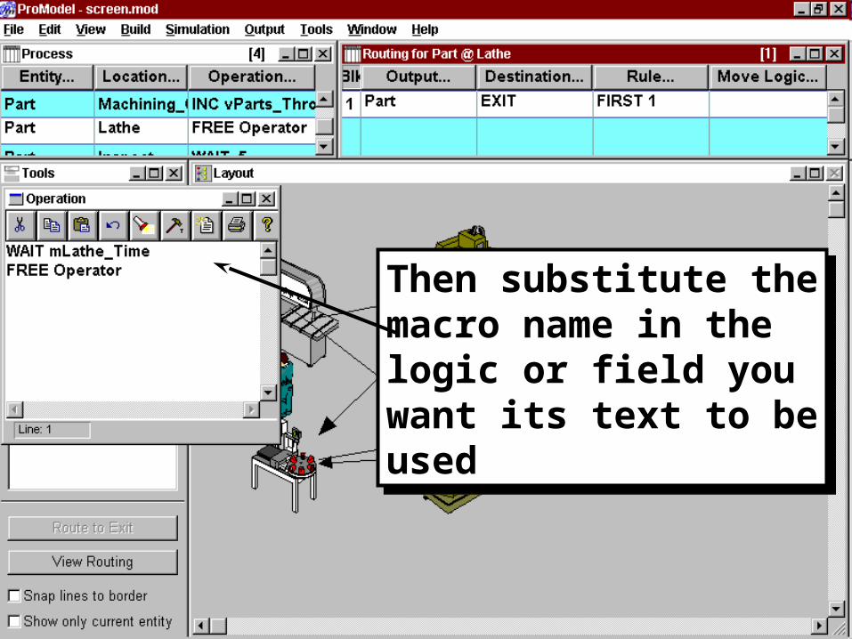
Then substitute themacro name in thelogic or field youwant its text to beused
Then substitute themacro name in thelogic or field youwant its text to beused

77
From the main menuselect SIMULATION -MODEL PARAMETERS
From the main menuselect SIMULATION -MODEL PARAMETERS
To change a macrovalue, click on theChange button.It brings up yourprompt
To change a macrovalue, click on theChange button.It brings up yourprompt

78
To develop model scenarios, use theSimulation - Scenarios optionTo develop model scenarios, use theSimulation - Scenarios option
To add orcreate a scenario,click on the Addbutton
To add orcreate a scenario,click on the Addbutton

79
Select Add
Provide Scenarioname
Change settings
Select Add
Provide Scenarioname
Change settings

80
After defining the sets of values you wish the RTIMacros to assume, save them as different Scenarios.Then select Simulation - Scenarios and selectRun Scenarios.
After defining the sets of values you wish the RTIMacros to assume, save them as different Scenarios.Then select Simulation - Scenarios and selectRun Scenarios.

81
Termination logic executes after the model finishesrunning.
It is most often used to do calculations withvariables that you want to represent a numeric valuethat cannot be calculated until all other values in themodel are completed. It is also used to writeinformation to an external file.

82
Operation Statements
GETCOST()
Returns the accumulated cost of the entityexecuting the statement.
To record this value for later viewing, placeit in a variable.
Syntax: vEntity_Cost = GETCOST()

83

84

85

86

87


