Download - 1.1.2 Faradaicand NonfaradaicProcesses
1.1.2 Faradaic and Nonfaradaic Processes
▪ Two types of electrochemical processes
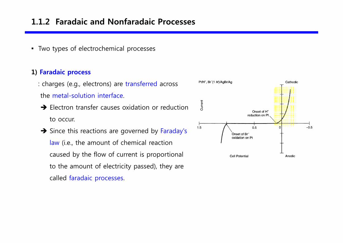
1) Faradaic process
: charges (e.g., electrons) are transferred across
the metal-solution interface.
� Electron transfer causes oxidation or reduction
to occur.
� Since this reactions are governed by Faraday's
law (i.e., the amount of chemical reaction
caused by the flow of current is proportional
to the amount of electricity passed), they are
called faradaic processes.
0.25 -2.1
1.1.2 Faradaic and Nonfaradaic Processes
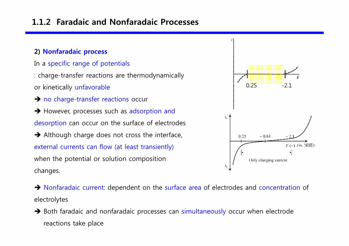
2) Nonfaradaic process
In a specific range of potentials
: charge-transfer reactions are thermodynamically
or kinetically unfavorable
� no charge-transfer reactions occur
� However, processes such as adsorption and
desorption can occur on the surface of electrodes
� Although charge does not cross the interface,
external currents can flow (at least transiently)
when the potential or solution composition
changes.
� Nonfaradaic current: dependent on the surface area of electrodes and concentration of
electrolytes
� Both faradaic and nonfaradaic processes can simultaneously occur when electrode
reactions take place
1.2.1 Ideal Polarized Electrode
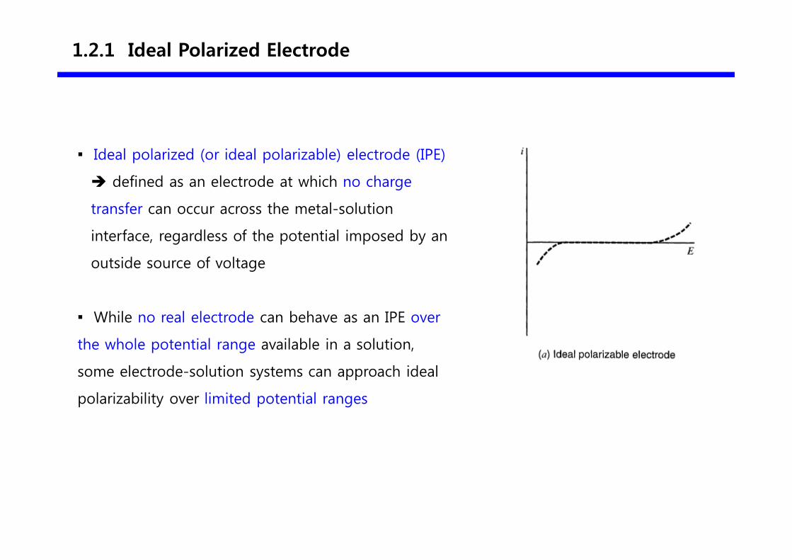
▪ Ideal polarized (or ideal polarizable) electrode (IPE)
� defined as an electrode at which no charge
transfer can occur across the metal-solution
interface, regardless of the potential imposed by an
outside source of voltage
▪ While no real electrode can behave as an IPE over
the whole potential range available in a solution,
some electrode-solution systems can approach ideal
polarizability over limited potential ranges
1.2.1 Ideal Polarized Electrode
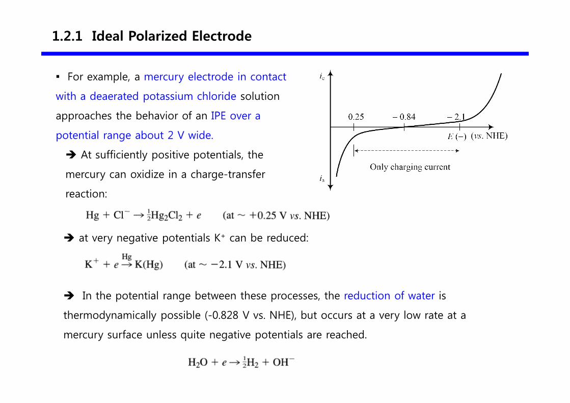
▪ For example, a mercury electrode in contact
with a deaerated potassium chloride solution
approaches the behavior of an IPE over a
potential range about 2 V wide.
� At sufficiently positive potentials, the
mercury can oxidize in a charge-transfer
reaction:
� at very negative potentials K+ can be reduced:
� In the potential range between these processes, the reduction of water is
thermodynamically possible (-0.828 V vs. NHE), but occurs at a very low rate at a
mercury surface unless quite negative potentials are reached.
1.2.2 Capacitance and Charge of an Electrode
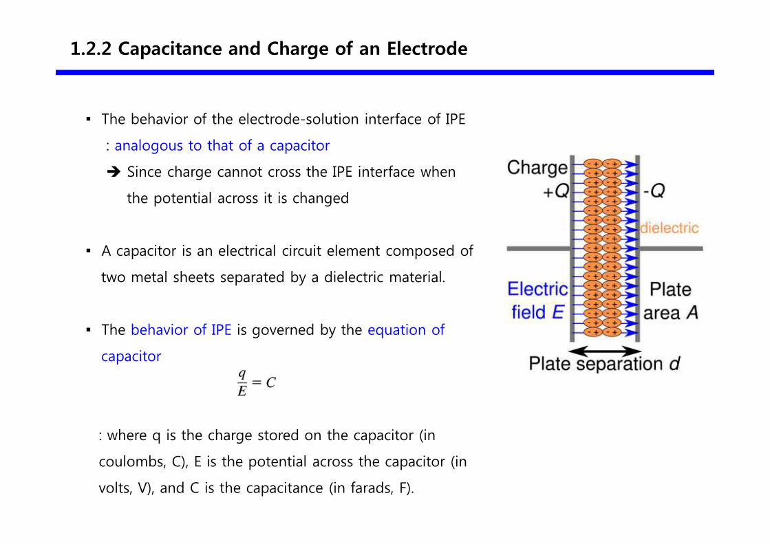
▪ The behavior of the electrode-solution interface of IPE
: analogous to that of a capacitor
� Since charge cannot cross the IPE interface when
the potential across it is changed
▪ A capacitor is an electrical circuit element composed of
two metal sheets separated by a dielectric material.
▪ The behavior of IPE is governed by the equation of
capacitor
: where q is the charge stored on the capacitor (in
coulombs, С), Е is the potential across the capacitor (in
volts, V), and С is the capacitance (in farads, F).

1.2.2 Capacitance and Charge of an Electrode
Principle of a capacitor
▪ When a potential is applied across a capacitor, charge will accumulate on its metal
plates until q satisfies the equation of q = CE
▪ During this charging process, a current (called the charging current) will flow.
▪ The charge on the capacitor consists of an excess of electrons on one plate, a
deficiency of electrons on the other, and a polarized dielectric
1.2.2 Capacitance and Charge of an Electrode
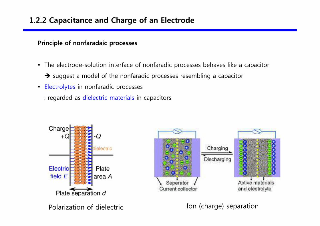
Principle of nonfaradaic processes
▪ The electrode-solution interface of nonfaradic processes behaves like a capacitor
� suggest a model of the nonfaradic processes resembling a capacitor
▪ Electrolytes in nonfaradic processes
: regarded as dielectric materials in capacitors
Polarization of dielectric Ion (charge) separation
1.2.2 Capacitance and Charge of an Electrode
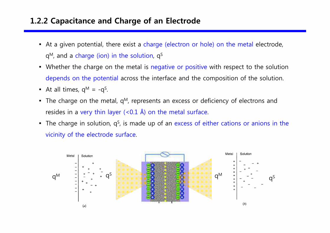
▪ At a given potential, there exist a charge (electron or hole) on the metal electrode,
qM, and a charge (ion) in the solution, qS
▪ Whether the charge on the metal is negative or positive with respect to the solution
depends on the potential across the interface and the composition of the solution.
▪ At all times, qM = -qS.
▪ The charge on the metal, qM, represents an excess or deficiency of electrons and
resides in a very thin layer (<0.1 Å) on the metal surface.
▪ The charge in solution, qS, is made up of an excess of either cations or anions in the
vicinity of the electrode surface.
qM qS qMqS
1.2.2 Capacitance and Charge of an Electrode
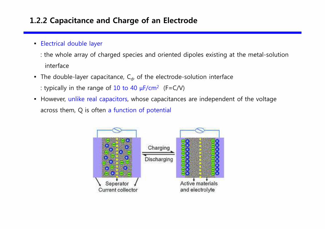
▪ Electrical double layer
: the whole array of charged species and oriented dipoles existing at the metal-solution
interface
▪ The double-layer capacitance, Cd, of the electrode-solution interface
: typically in the range of 10 to 40 μF/cm2 (F=C/V)
▪ However, unlike real capacitors, whose capacitances are independent of the voltage
across them, Q is often a function of potential
1.2.3 Brief Description of the Electrical Double Layer
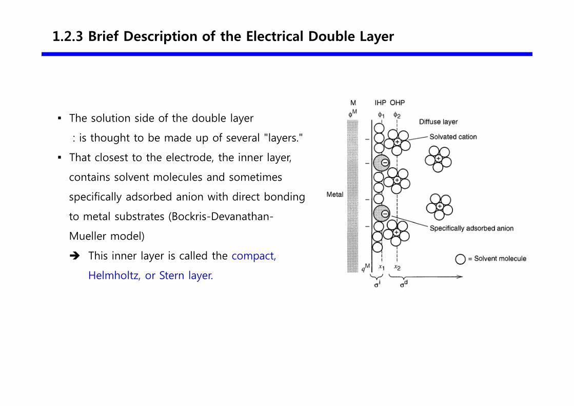
▪ The solution side of the double layer
: is thought to be made up of several "layers."
▪ That closest to the electrode, the inner layer,
contains solvent molecules and sometimes
specifically adsorbed anion with direct bonding
to metal substrates (Bockris-Devanathan-
Mueller model)
� This inner layer is called the compact,
Helmholtz, or Stern layer.
1.2.3 Brief Description of the Electrical Double Layer
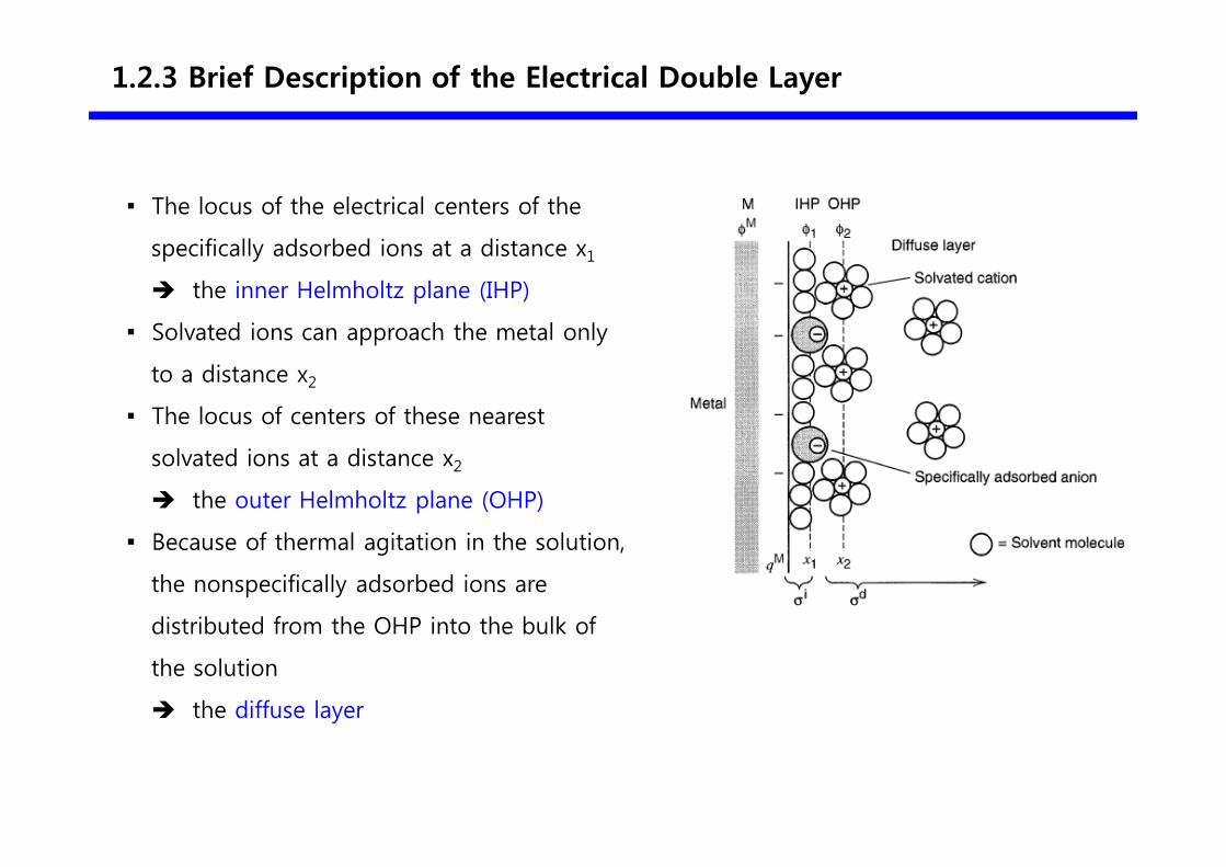
▪ The locus of the electrical centers of the
specifically adsorbed ions at a distance x1
� the inner Helmholtz plane (IHP)
▪ Solvated ions can approach the metal only
to a distance x2
▪ The locus of centers of these nearest
solvated ions at a distance x2
� the outer Helmholtz plane (OHP)
▪ Because of thermal agitation in the solution,
the nonspecifically adsorbed ions are
distributed from the OHP into the bulk of
the solution
� the diffuse layer
1.2.3 Brief Description of the Electrical Double Layer
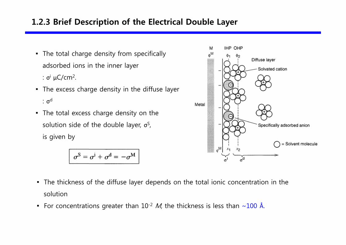
▪ The total charge density from specifically
adsorbed ions in the inner layer
: σi μC/cm2.
▪ The excess charge density in the diffuse layer
: σd
▪ The total excess charge density on the
solution side of the double layer, σS,
is given by
▪ The thickness of the diffuse layer depends on the total ionic concentration in the
solution
▪ For concentrations greater than 10-2 M, the thickness is less than ~100 Å.
1.2.3 Brief Description of the Electrical Double Layer
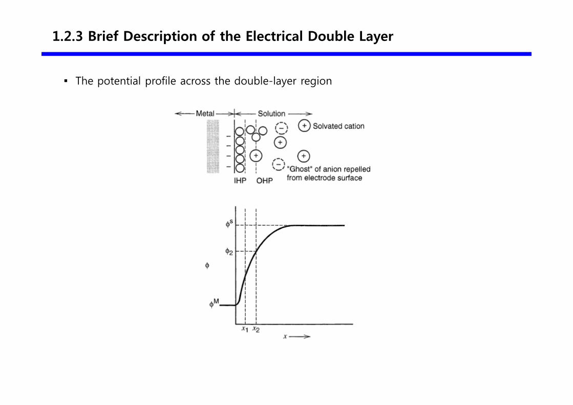
▪ The potential profile across the double-layer region
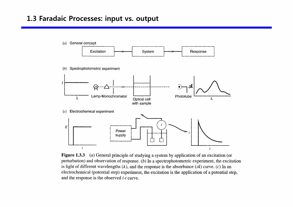
1.3 Faradaic Processes: input vs. output
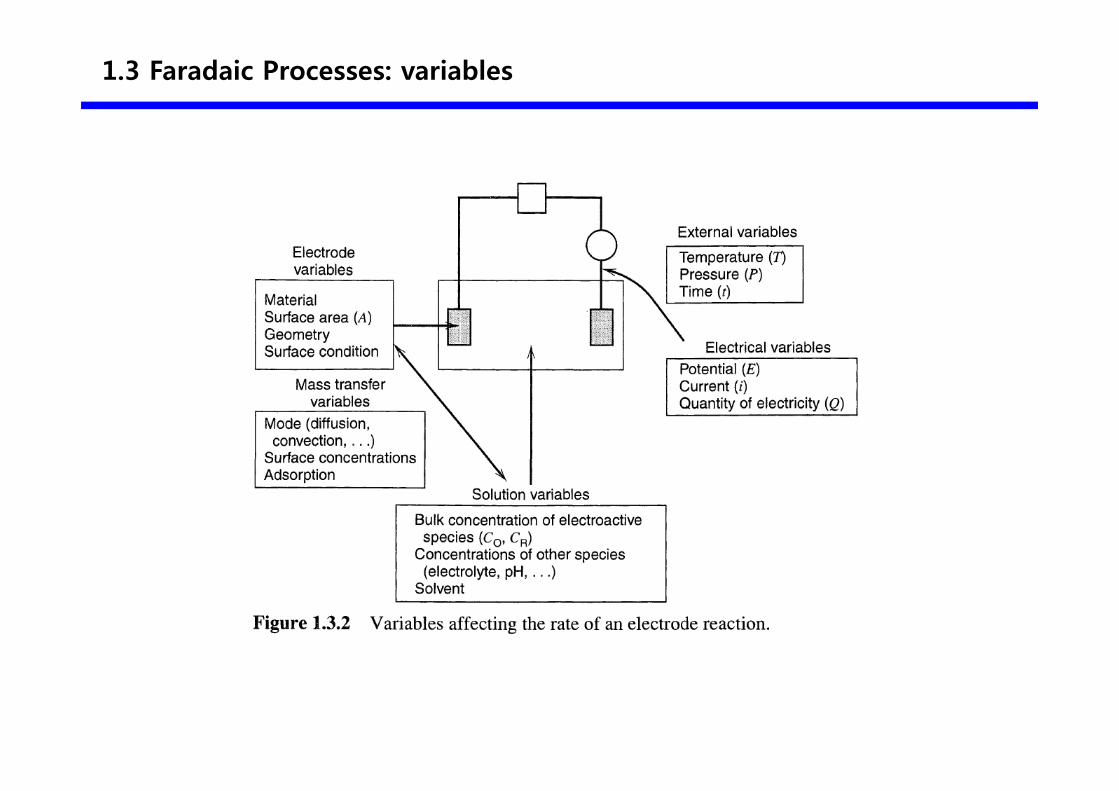
1.3 Faradaic Processes: variables
1.2.4 Double-Layer Capacitance and Charging Current in Electrochemical Measurements
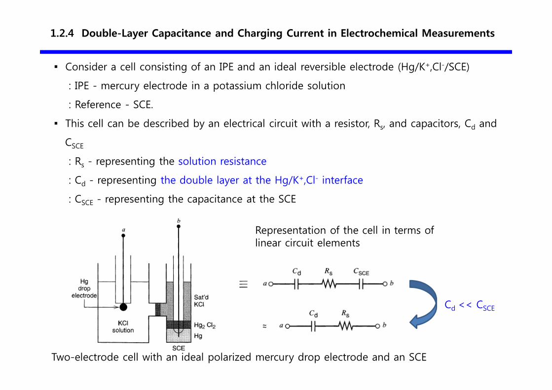
▪ Consider a cell consisting of an IPE and an ideal reversible electrode (Hg/K+,Cl-/SCE)
: IPE - mercury electrode in a potassium chloride solution
: Reference - SCE.
▪ This cell can be described by an electrical circuit with a resistor, Rs, and capacitors, Cd and
CSCE
: Rs - representing the solution resistance
: Cd - representing the double layer at the Hg/K+,Cl- interface
: CSCE - representing the capacitance at the SCE
Representation of the cell in terms of linear circuit elements
Two-electrode cell with an ideal polarized mercury drop electrode and an SCE
Cd << CSCE
1.2.4 Double-Layer Capacitance and Charging Current in Electrochemical Measurements
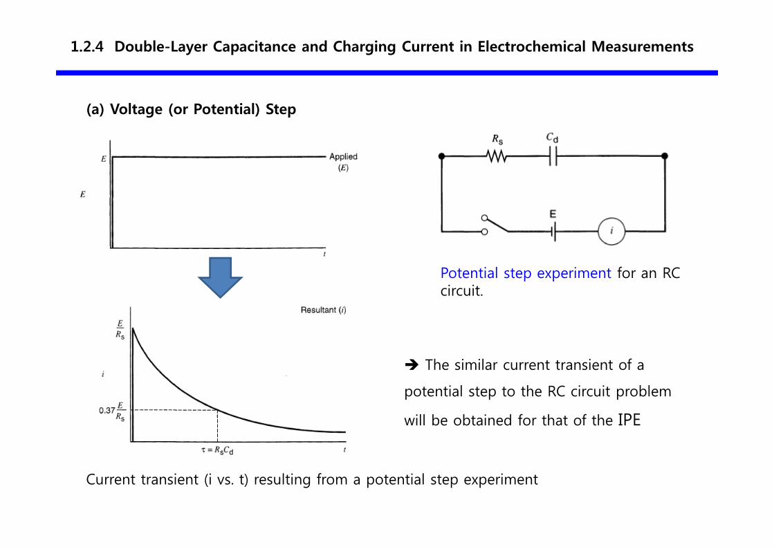
(a) Voltage (or Potential) Step
Current transient (i vs. t) resulting from a potential step experiment
Potential step experiment for an RC circuit.
� The similar current transient of a
potential step to the RC circuit problem
will be obtained for that of the IPE
1.2.4 Double-Layer Capacitance and Charging Current in Electrochemical Measurements
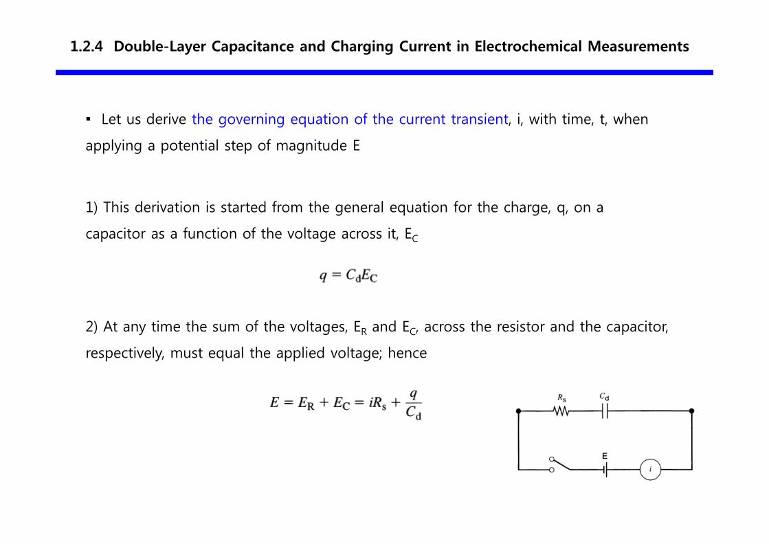
▪ Let us derive the governing equation of the current transient, i, with time, t, when
applying a potential step of magnitude E
1) This derivation is started from the general equation for the charge, q, on a
capacitor as a function of the voltage across it, EC
2) At any time the sum of the voltages, ER and EC, across the resistor and the capacitor,
respectively, must equal the applied voltage; hence
1.2.4 Double-Layer Capacitance and Charging Current in Electrochemical Measurements
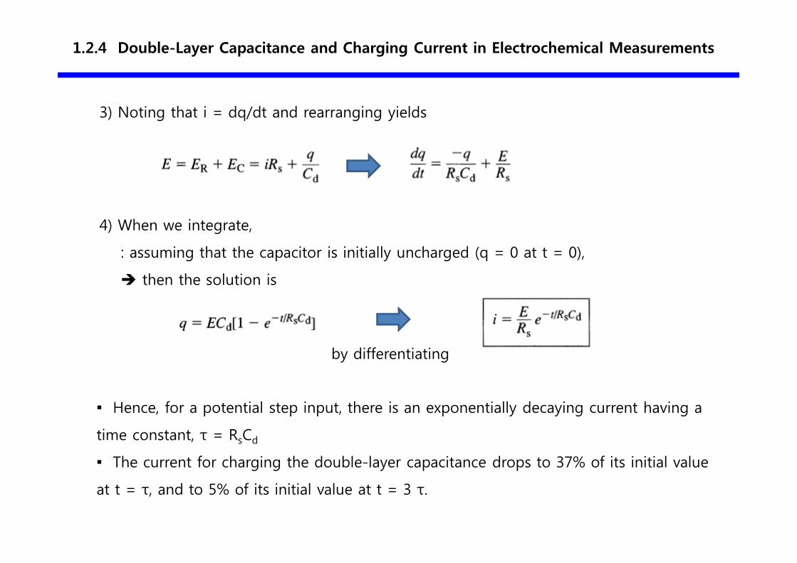
3) Noting that i = dq/dt and rearranging yields
4) When we integrate,
: assuming that the capacitor is initially uncharged (q = 0 at t = 0),
� then the solution is
▪ Hence, for a potential step input, there is an exponentially decaying current having a
time constant, τ = RsCd
▪ The current for charging the double-layer capacitance drops to 37% of its initial value
at t = τ, and to 5% of its initial value at t = 3 τ.
by differentiating
1.2.4 Double-Layer Capacitance and Charging Current in Electrochemical Measurements
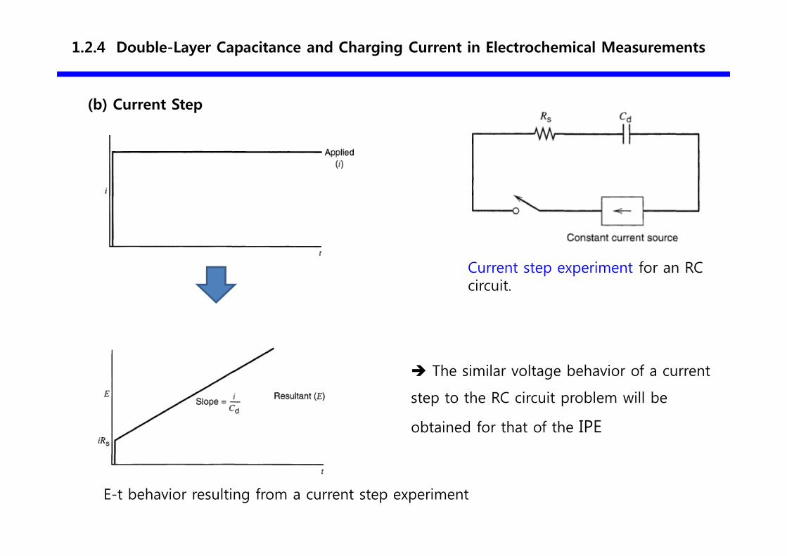
(b) Current Step
E-t behavior resulting from a current step experiment
Current step experiment for an RC circuit.
� The similar voltage behavior of a current
step to the RC circuit problem will be
obtained for that of the IPE
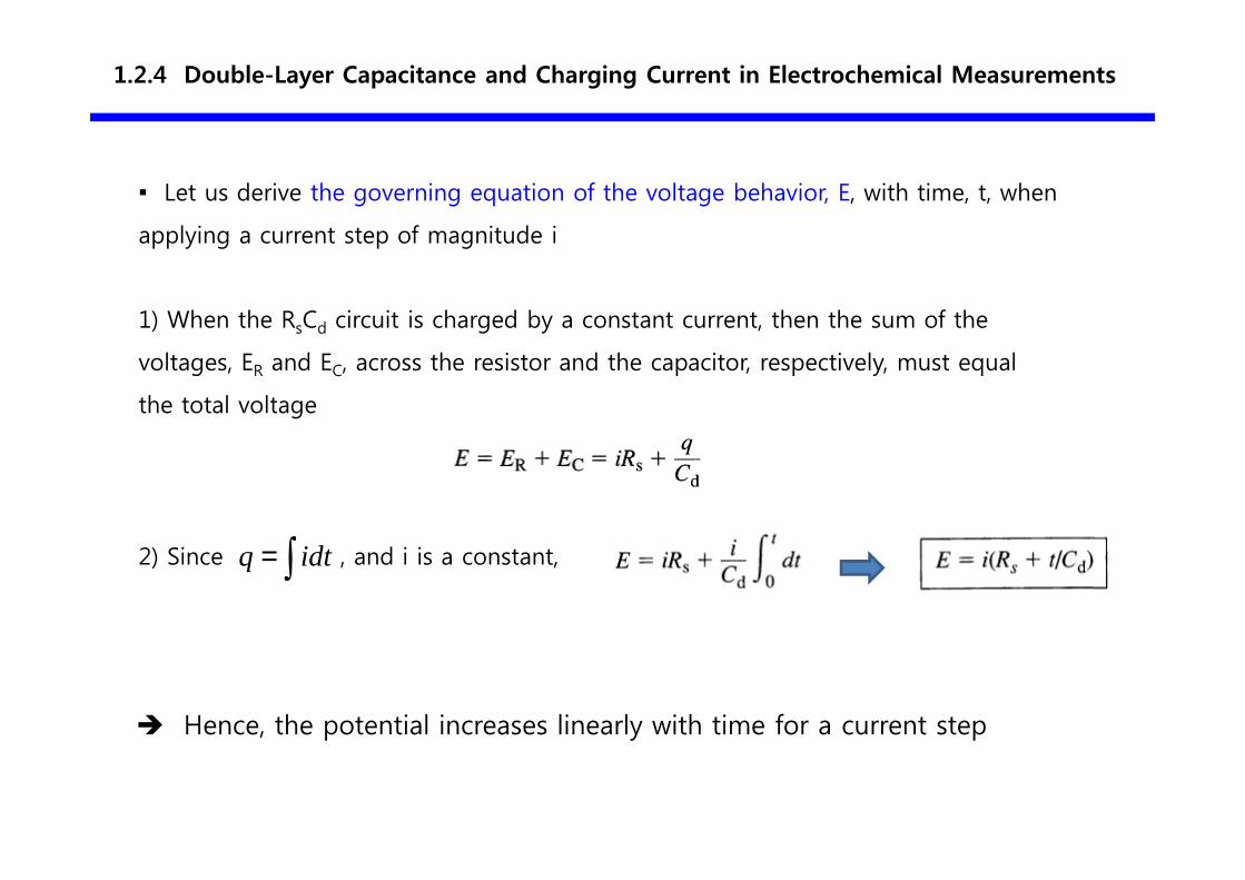
1) When the RsCd circuit is charged by a constant current, then the sum of the
voltages, ER and EC, across the resistor and the capacitor, respectively, must equal
the total voltage
∫= idtq
� Hence, the potential increases linearly with time for a current step
1.2.4 Double-Layer Capacitance and Charging Current in Electrochemical Measurements
▪ Let us derive the governing equation of the voltage behavior, E, with time, t, when
applying a current step of magnitude i
2) Since , and i is a constant,
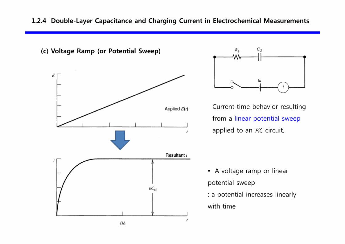
(c) Voltage Ramp (or Potential Sweep)
Current-time behavior resulting
from a linear potential sweep
applied to an RC circuit.
1.2.4 Double-Layer Capacitance and Charging Current in Electrochemical Measurements
▪ A voltage ramp or linear
potential sweep
: a potential increases linearly
with time
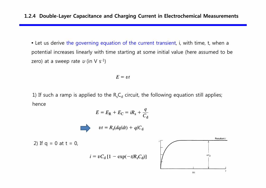
▪ Let us derive the governing equation of the current transient, i, with time, t, when a
potential increases linearly with time starting at some initial value (here assumed to be
zero) at a sweep rate υ (in V s-1)
1) If such a ramp is applied to the RsCd circuit, the following equation still applies;
hence
2) If q = 0 at t = 0,
1.2.4 Double-Layer Capacitance and Charging Current in Electrochemical Measurements
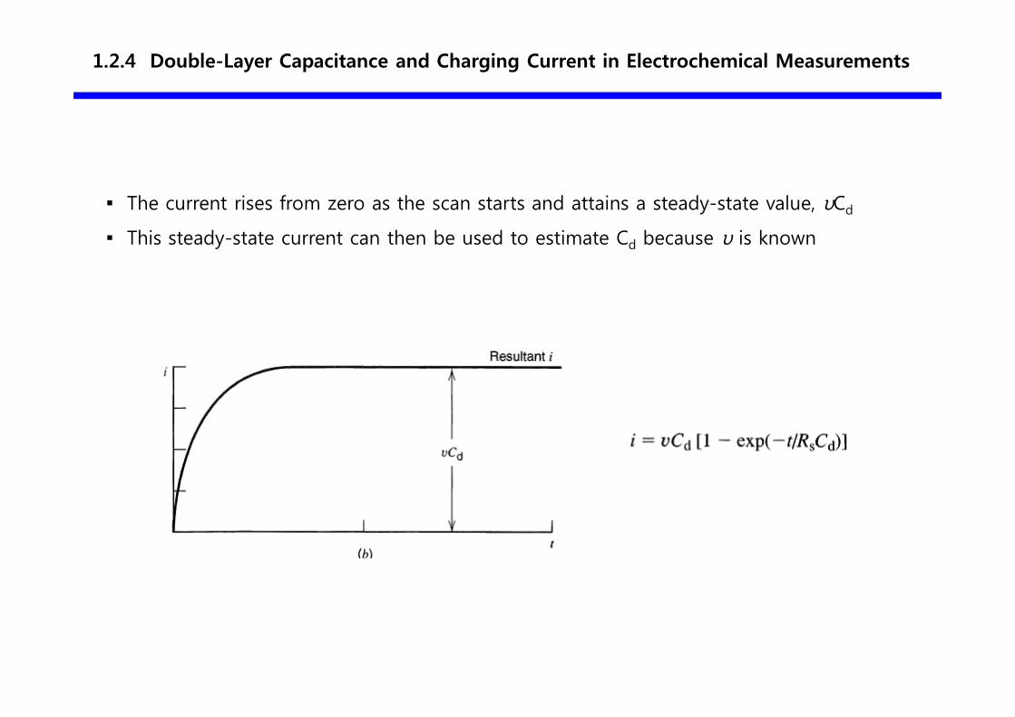
▪ The current rises from zero as the scan starts and attains a steady-state value, υCd
▪ This steady-state current can then be used to estimate Cd because υ is known
1.2.4 Double-Layer Capacitance and Charging Current in Electrochemical Measurements
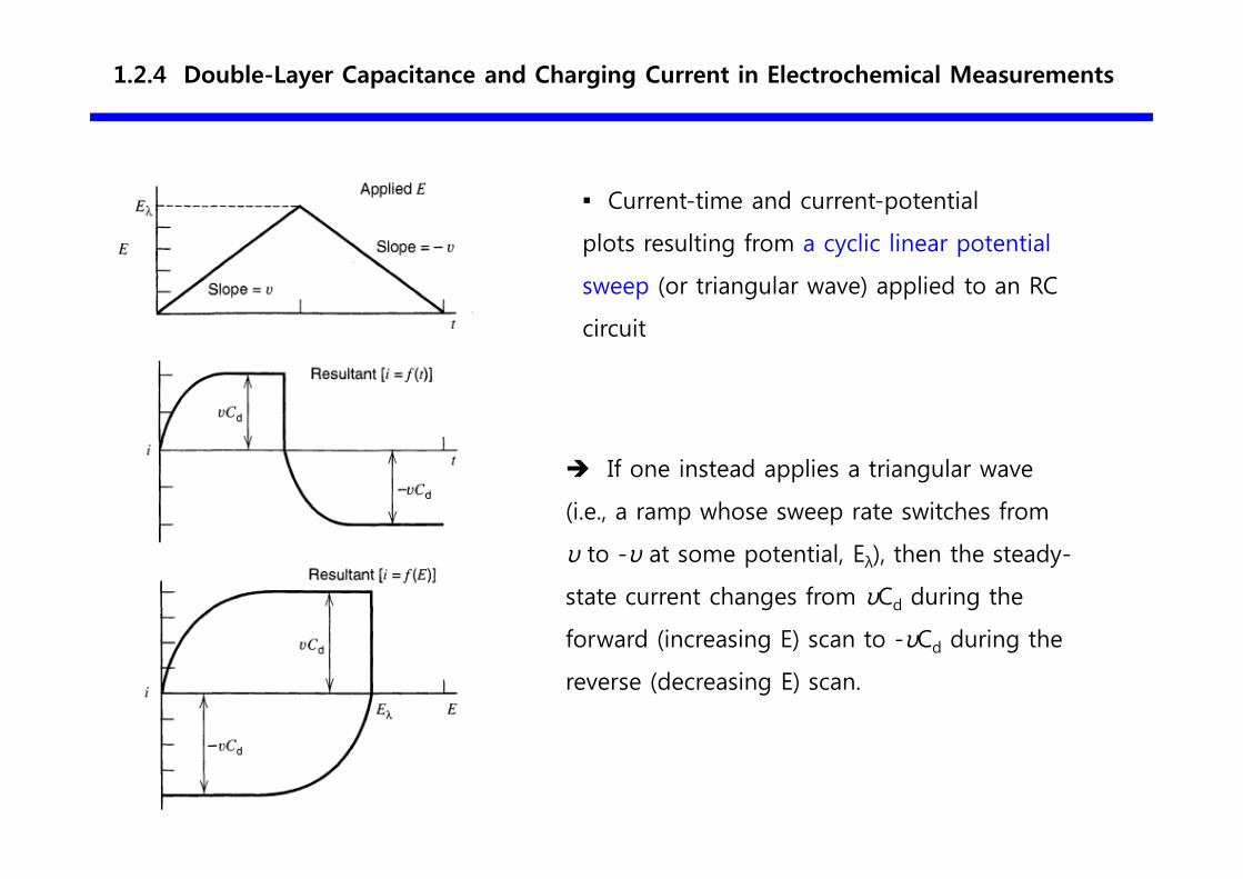
▪ Current-time and current-potential
plots resulting from a cyclic linear potential
sweep (or triangular wave) applied to an RC
circuit
1.2.4 Double-Layer Capacitance and Charging Current in Electrochemical Measurements
� If one instead applies a triangular wave
(i.e., a ramp whose sweep rate switches from
υ to -υ at some potential, Eλ), then the steady-
state current changes from υCd during the
forward (increasing E) scan to -υCd during the
reverse (decreasing E) scan.
1.2.4 Double-Layer Capacitance and Charging Current in Electrochemical Measurements
Note:
▪ Cd is generally a function of potential for nonfaradaic processes
▪ The approximate results can be obtained using an "average" Cd over the potential
range.
▪ The proposed model in terms of circuit elements is strictly accurate only for
experiments where the overall cell potential does not change very much.
1.3.1 Electrochemical Cells—Types and Definitions
▪ Two types of Electrochemical cells in which faradaic currents
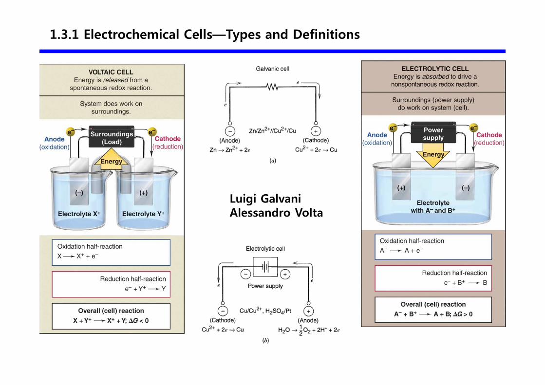
1) Galvanic cell
� Reactions occur spontaneously at the electrodes when they are connected externally
by a conductor
� These cells are often employed in converting chemical energy into electrical energy.
� Galvanic cells of commercial importance include primary batteries and fuel cells
2) Electrolytic cell
� Reactions are driven by the imposition of an external voltage greater than the
open-circuit potential of the cell
� Electroplating, production of chlorine, charging process of rechargeable batteries
1.3.1 Electrochemical Cells—Types and Definitions
Luigi GalvaniAlessandro Volta
Cathode vs. Anode
▪ Cathode
: the electrode at which reductions occur
▪ Anode
: the electrode at which oxidations occur the anode.
▪ Cathodic current
: a current in which electrons cross the interface from the electrode to a species in
solution
▪ Anodic current
: a current in which electron flow from a solution species into the electrode
1.3 Faradaic Processes
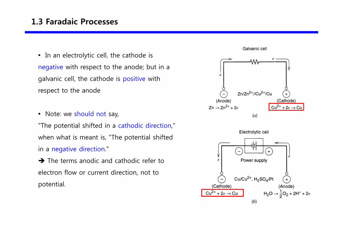
▪ In an electrolytic cell, the cathode is
negative with respect to the anode; but in a
galvanic cell, the cathode is positive with
respect to the anode
▪ Note: we should not say,
"The potential shifted in a cathodic direction,"
when what is meant is, "The potential shifted
in a negative direction."
� The terms anodic and cathodic refer to
electron flow or current direction, not to
potential.
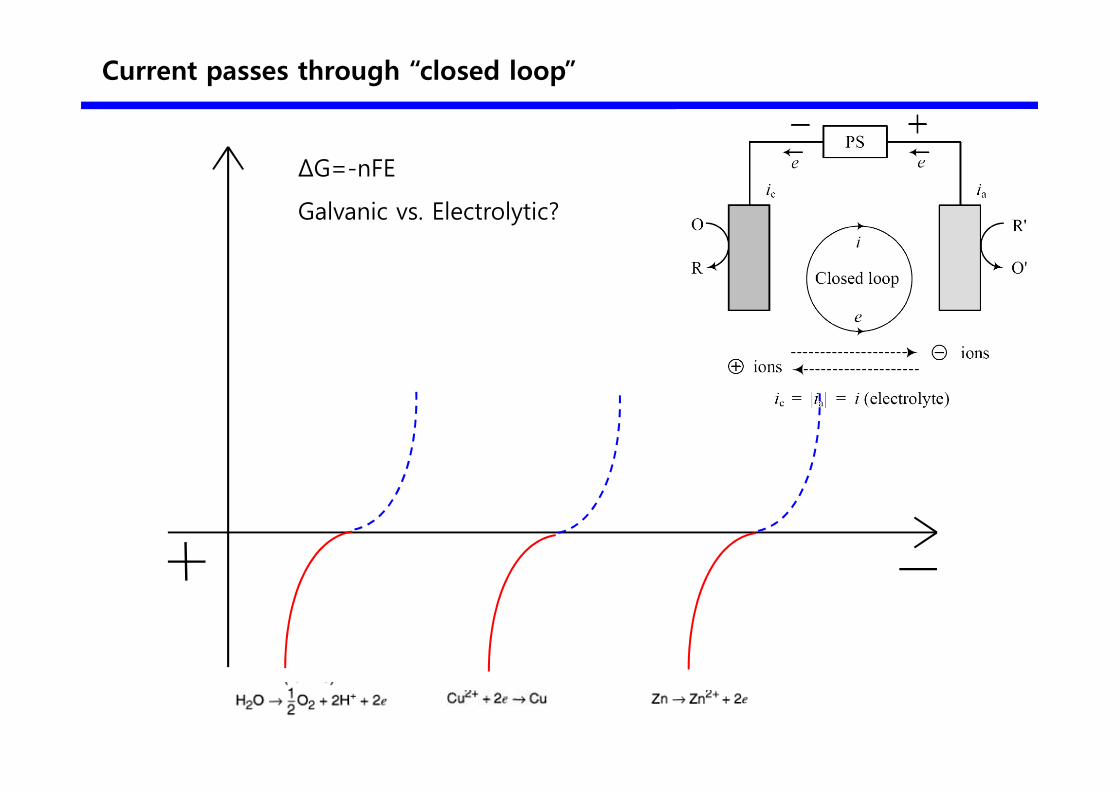
Current passes through “closed loop”
ΔG=-nFE
Galvanic vs. Electrolytic?
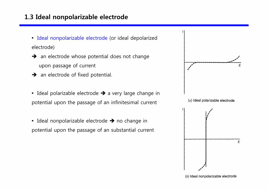
1.3 Ideal nonpolarizable electrode
▪ Ideal nonpolarizable electrode (or ideal depolarized
electrode)
� an electrode whose potential does not change
upon passage of current
� an electrode of fixed potential.
▪ Ideal polarizable electrode � a very large change in
potential upon the passage of an infinitesimal current
▪ Ideal nonpolarizable electrode � no change in
potential upon the passage of an substantial current
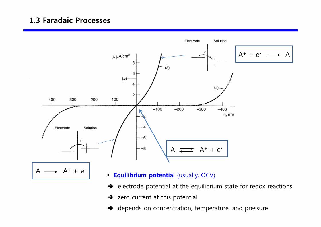
1.3 Faradaic Processes
▪ Equilibrium potential (usually, OCV)
� electrode potential at the equilibrium state for redox reactions
� zero current at this potential
� depends on concentration, temperature, and pressure
A+ + e- A
A+ + e-A
A+ + e-A


