
BY:
VIJAY SHARMA ENGINEER
120 / 240 VAC SINGLE SPLIT PHASE & MULTI-WIRE BRANCH CIRCUITSExcerpt from Inverter Charger Series Manual
| SAMLEX AMERICA SAMLEX AMERICA |
120 / 240 VAC SINGLE SPLIT PHASE & MULTI-WIRE BRANCH CIRCUITS
1
i INFO
For purposes of explaining the concept of Multi-wire Branch Circuits, Neutral to Ground bonding and Equipment Grounding Conductor (EGC) have not been shown in the schematic diagrams.
1.0 120/240 VAC SINGlE SplIt phASE SyStEM Inverters and Inverter Chargers are frequently connected to a building / structure / house that has been previously completely wired for 120 / 240
VAC Single Split Phase System and has a standard Service Entrance Panel / Load Center / Distribution Panel – See Fig. 1.
120/240 VAC Single Split Phase Utility Power to the building / structure / house is fed from a Distribution Transformer that is either mounted on a utility pole (feeds through overhead lines) or on the ground on a concrete pad (Pad mounted, feeding through underground lines). This power enters the building / structure / house through the Service Entrance Panel for further internal distribution.
1.1 Service Entrance panel For 120 / 240 VAC Split phase AC power Distribution
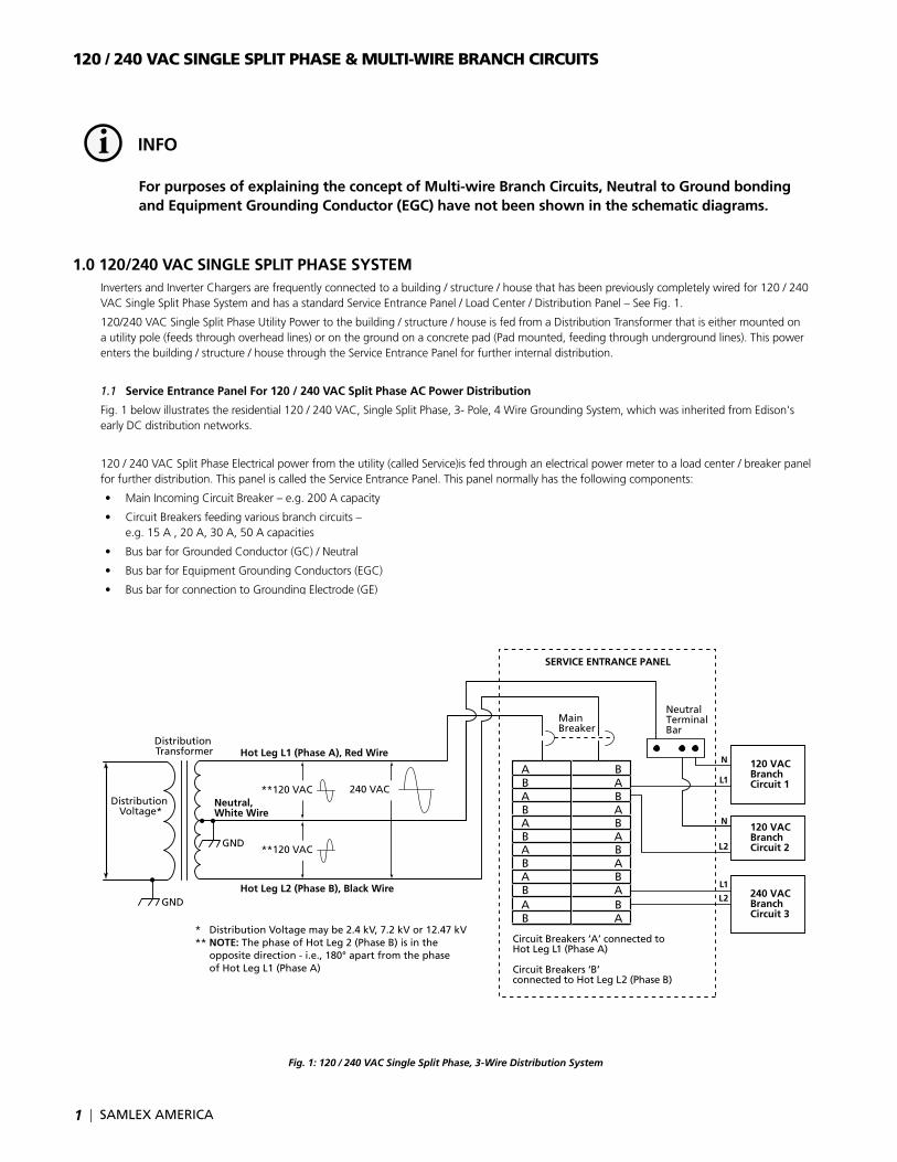
Fig. 1 below illustrates the residential 120 / 240 VAC, Single Split Phase, 3- Pole, 4 Wire Grounding System, which was inherited from Edison's early DC distribution networks.
120 / 240 VAC Split Phase Electrical power from the utility (called Service)is fed through an electrical power meter to a load center / breaker panel for further distribution. This panel is called the Service Entrance Panel. This panel normally has the following components:
• MainIncomingCircuitBreaker–e.g.200Acapacity
• CircuitBreakersfeedingvariousbranchcircuits– e.g. 15 A , 20 A, 30 A, 50 A capacities
• BusbarforGroundedConductor(GC)/Neutral
• BusbarforEquipmentGroundingConductors(EGC)
• BusbarforconnectiontoGroundingElectrode(GE)
• SystemBondingJumper(SBJ)
Fig. 1: 120 / 240 VAC Single Split Phase, 3-Wire Distribution System
ABABABABABAB
BABABABABABA
Circuit Breakers ‘A’ connected to Hot Leg L1 (Phase A)
Circuit Breakers ‘B’ connected to Hot Leg L2 (Phase B)
SERVICE ENTRANCE PANEL
Distribution Voltage*
Distribution Transformer
* Distribution Voltage may be 2.4 kV, 7.2 kV or 12.47 kV** NOTE: The phase of Hot Leg 2 (Phase B) is in the opposite direction - i.e., 180° apart from the phase of Hot Leg L1 (Phase A)
Hot Leg L1 (Phase A), Red Wire
Hot Leg L2 (Phase B), Black Wire
Neutral, White Wire
GND
Neutral Terminal Bar
N
L1
N
L2
L1
L2
120 VACBranch Circuit 1
120 VACBranch Circuit 2
240 VACBranch Circuit 3
**120 VAC 240 VAC
**120 VAC
Main Breaker
GND
SAMLEX AMERICA |
120 / 240 VAC SINGLE SPLIT PHASE & MULTI-WIRE BRANCH CIRCUITS
2
The primary side of the Distribution Transformer is connected between Ground and one of the 2400V, 7.2 kV, 12.47 kV, 13.2 kV or 13.8 kV phasesoftheutilitycompany's3-PhaseDistributionNetwork.ThesecondaryoftheDistributionTransformerhasagroundedcentertapandiswound in a manner that supplies two 120 VAC phases which are 180° out of phase with each other (Split Phases). In urban areas, one Distribution Transformer typically supplies 1-6 residences.
The center-tapped configuration of the secondary side of the Distribution Transformer provides following voltages to the Service Entrance Panel:
• 120VACbetweentheHotLegL1(PhaseA,Redwire)andthegrounded,centertappedNeutral(Whitewire).TheoscilloscopetraceofthevoltagewaveformbetweentheHotLegL1andNeutralshowsthevoltagerisinginthePositivedirectionatthestartofthewaveform
• 120VACbetweentheHotLegL2(PhaseB,Blackwire)andthegrounded,centertappedNeutral(Whitewire).PleasenotethatthecorrespondingoscilloscopetraceofthevoltagewaveformbetweentheHotLegL2andNeutralshowsthevoltagerisingintheNegativedirection at the start of the waveform. this indicates that the two 120 VAC voltages are 180 degrees out of phase.
• 240VACbetweentheHotLegL1(PhaseA,Redwire)andtheHotLegL2(PhaseB,Blackwire)
A part of a typical Service Entrance Panel with interleaved type of bus bar arrangement with 2-columns of branch circuit breakers (marked “A” and“B”)isshowninFig.8.1.EachFullSizedBreaker(marked“A”or“B”)originatesontheoppositephasefromtheoneaboveorbelowit.Breakersmarked“A”areconnectedtotheHotLegL1(PhaseA)andbreakersmarked“B”areconnectedtotheHotLegL2(PhaseB).GoingdownacolumnofFullSizeBreakers,theywillbeinaphasesequenceofA-B-A-B…
• 120VACbranchcircuitloadsareconnectedbetweenabreakeronPhaseA(HotLegL1,Redwire)andNeutral(N,Whitewire)asshownforBranchCircuit1orbetweenabreakeronPhaseB(HotLegL2,Blackwire)andNeutral(N,Whitewire)asshownforBranchCircuit2
• 240VbranchcircuitloadsareconnectedbetweenabreakeronPhaseA(HotLegL1,Redwire)andPhaseB(HotLegL2,Blackwire)asshownforBranchCircuit3.
2.0 MultI-WIrE BrANCh CIrCuItS As explained above, in a utility-connected, 120 / 240 VAC Single Split Phase System, the 120 / 240 VAC power consists of two 120 VAC lines
viz.HotL1(PhaseA,Redwire)andHotL2(PhaseB,Blackwire)thatare180degreesoutofphasewithrespecttothecentertapped,groundedNeutral(Whitewire)–seeFig.1
Itispossibletowiretwoseparate120VACBranchCircuitsfedfromthe2splitphasesHotL1(PhaseA,Redwire)andHotL2(PhaseB,Blackwire)usingasinglecommonNeutral(Whitewire)insteadoftwoseparateNeutrals(Whitewires)–Seethetwo15ABranchCircuitsfeedingthe2receptaclesshowninFigs.8.4.ThistypeofconnectioniscalledaMulti-wireBranchCircuit.Asthephasesofthetwo15A,120VACBranchCircuitsfeedingthe2receptaclesare180degreesapartandopposeeachother,thenetcurrentflowinginthecommonNeutral(Whitewire)willbeequaltothedifferenceofthecurrentsinthetwoBranchCircuits(15A–15A=0A).ThemaximumcurrentflowinginthecommonNeutralwillbelimitedtothebreakercapacity(MaximumcurrentwillflowinthecommonNeutralwhenoneofthesplitphasebranchcircuitsisnotloadedandtheloadedsplitphasebranchcircuitisdrawingitsfullratedcapacity).PropersafetyguidelinesforMulti-wireBranchCircuitsaretobeadheredtoaslaiddowninSection100oftheNationalElectricalCode(NEC).
WArNING!
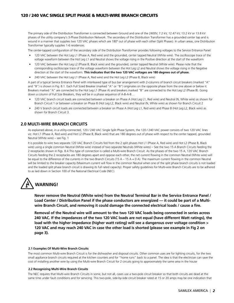
Never remove the Neutral (White wire) from the Neutral terminal Bar in the Service Entrance panel / load Center / Distribution panel if the phase conductors are energized — it could be part of a Multi-wire Branch Circuit, and removing it could damage the connected electrical loads / cause a fire.
removal of the Neutral wire will amount to the two 120 VAC loads being connected in series across 240 VAC. If the impedances of the two 120 VAC loads are not equal (have different Watt ratings), the load with the higher impedance (higher watt rating) will see a dangerous over voltage condition > 120 VAC and may reach 240 VAC in case the other load is shorted (please see example in Fig 2 on page 3).
2.1 Examples Of Multi-Wire Branch Circuits
ThemostcommonMulti-wireBranchCircuitisforthedishwasheranddisposalcircuits.Othercommonusesareforlightingcircuits,forthetwosmall appliance branch circuits required at the kitchen counters and for “home runs” back to a panel. The idea is that the electrician can save the costofinstallinganotherwirebyusingtheMulti-wireBranchCircuitfor2circuitsgoingtoapproximatelythesameareainthehouse
2.2 recognizing Multi-Wire Branch Circuits
TheNECrequiresthatMulti-wireBranchCircuitsinsome,butnotall,casesuseatwo-polecircuitbreakersothatbothcircuitsaredeadatthesame time under fault conditions and for servicing. This two-pole, side-by-side circuit breaker rated at 15 or 20 amps may be one indication that
| SAMLEX AMERICA SAMLEX AMERICA |
120 / 240 VAC SINGLE SPLIT PHASE & MULTI-WIRE BRANCH CIRCUITS
Multi-wireBranchCircuitshavebeenused.Commonhandle(ganged)circuitbreakersratedat30ampsandhigherareusuallydedicatedto 240 Volt circuits for ranges, hot water heaters, dryers, and the like.
Examination of the wiring in the Service Entrance Panel / Load Center / Distribution Panel may show a three-wire cable (14 or 12 AWG red, black, andwhiteconductors)withbaregroundleavingtheServiceEntrancePanel/LoadCenter/DistributionPanel.ThismaybeconnectedtoaMulti-wireBranchCircuit.ThecircuitbreakersconnectedtothiscableandtheoutputsofthiscableshouldbetracedtodeterminethepresenceorabsenceofaMulti-wireBranchCircuit.
3.0 OVEr-lOADING OF COMMON NEutrAl CONDuCtOr IN thE MultI-WIrE BrANCh CIrCuItS
3.1 When An Inverter Is Connected Directly to 120 / 240 VAC Service Entrance panel / load Center / Distribution panel
Asexplainedabove,aMulti-wireBranchCircuitoperatesnormallyandsafelyonlywhenthetwoseparate120VACBranchCircuitsarefedfromthe2splitphasesL1(PhaseA,Redwire)andL2(PhaseB,Blackwire)thatare180degreesapartandwhichresultsinalowercurrentflowinthesinglecommonNeutral(thiscurrentwillbe=thedifferenceinthecurrentsinthetwoindividualSplitPhaseBranchCircuits).
Each branch circuit in the Service Entrance Panel / Load Center / Distribution Panel is protected by a circuit breaker in the hot, ungrounded current carryingconductorfedfromtheHotLegL1/L2.Thisungrounded,currentcarryingconductorissizedbasedontheAmpereratingofthecircuitbreaker.TheNeutral,groundedcurrentcarryingconductorisusuallythesamesizeastheHotungroundedcurrentcarryingconductorfedfromtheHotLegL1/L2.ThisNeutralconductorwillbeoverloaded/overheatedifitisforcedtocarrycurrenthigherthantheAmpereratingofthecircuitbreakerresultinginfireandsafetyhazard.
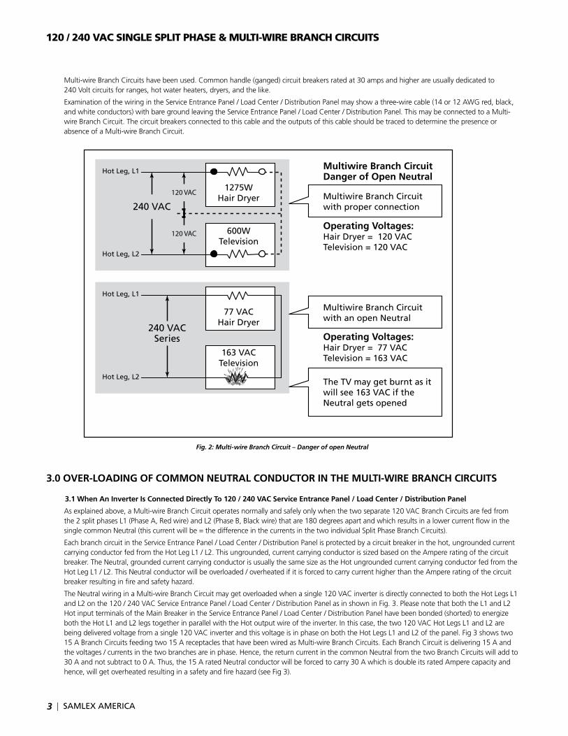
TheNeutralwiringinaMulti-wireBranchCircuitmaygetoverloadedwhenasingle120VACinverterisdirectlyconnectedtoboththeHotLegsL1and L2 on the 120 / 240 VAC Service Entrance Panel / Load Center / Distribution Panel as in shown in Fig. 3. Please note that both the L1 and L2 HotinputterminalsoftheMainBreakerintheServiceEntrancePanel/LoadCenter/DistributionPanelhavebeenbonded(shorted)toenergizeboththeHotL1andL2legstogetherinparallelwiththeHotoutputwireoftheinverter.Inthiscase,thetwo120VACHotLegsL1andL2arebeingdeliveredvoltagefromasingle120VACinverterandthisvoltageisinphaseonboththeHotLegsL1andL2ofthepanel.Fig3showstwo15ABranchCircuitsfeedingtwo15AreceptaclesthathavebeenwiredasMulti-wireBranchCircuits.EachBranchCircuitisdelivering15Aandthevoltages/currentsinthetwobranchesareinphase.Hence,thereturncurrentinthecommonNeutralfromthetwoBranchCircuitswilladdto30Aandnotsubtractto0A.Thus,the15AratedNeutralconductorwillbeforcedtocarry30AwhichisdoubleitsratedAmperecapacityandhence,willgetoverheatedresultinginasafetyandfirehazard(seeFig3).
3
Fig. 2: Multi-wire Branch Circuit – Danger of open Neutral
Multiwire Branch CircuitDanger of Open Neutral
Multiwire Branch Circuitwith proper connection
Multiwire Branch Circuitwith an open Neutral
Operating Voltages:Hair Dryer = 120 VACTelevision = 120 VAC
Operating Voltages:Hair Dryer = 77 VACTelevision = 163 VAC
The TV may get burnt as it will see 163 VAC if the Neutral gets opened
240 VAC
240 VACSeries
120 VAC
120 VAC
1275WHair Dryer
600WTelevision
77 VACHair Dryer
163 VACTelevision
Hot Leg, L1
Hot Leg, L2
Hot Leg, L1
Hot Leg, L2
SAMLEX AMERICA |
120 / 240 VAC SINGLE SPLIT PHASE & MULTI-WIRE BRANCH CIRCUITS
4
4.0 OptIONS FOr OVErCOMING OVEr-lOADING OF COMMON NEutrAl CONDuCtOr IN thE MultI-WIrE BrANCh CIrCuItS
When An Inverter Is Connected Directly to 120 / 240 V Service Entrance panel / load Center / Distribution panel
The following options are suggested for dealing with this problem:
• DisconnectorrewiretheMulti-wireBranchCircuitsasseparatecircuits(alsocalled“homerun”)fromtheServiceEntrancePanel/LoadCenter / Distribution Panel.
• Connectboth"Hot"(ungrounded)conductorsoftheMulti-wireBranchCircuittoasinglecircuitbreakerratedfortheampacityoftheNeutralconductor.
• LimittheoutputoftheinverterwithacircuitbreakerratedattheampacityoftheNeutralconductor(usually15amps).Placeawarningnearthis circuit breaker stating that the rating must not be increased.
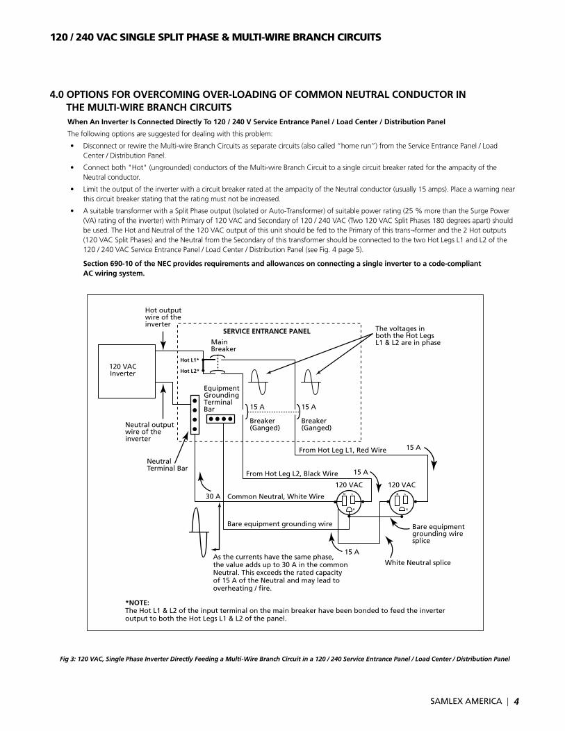
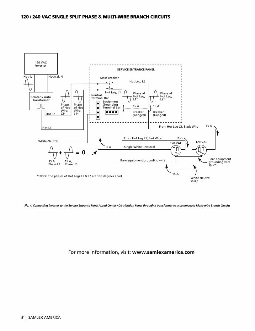
• AsuitabletransformerwithaSplitPhaseoutput(IsolatedorAuto-Transformer)ofsuitablepowerrating(25%morethantheSurgePower(VA) rating of the inverter) with Primary of 120 VAC and Secondary of 120 / 240 VAC (Two 120 VAC Split Phases 180 degrees apart) should beused.TheHotandNeutralofthe120VACoutputofthisunitshouldbefedtothePrimaryofthistrans¬formerandthe2Hotoutputs(120VACSplitPhases)andtheNeutralfromtheSecondaryofthistransformershouldbeconnectedtothetwoHotLegsL1andL2ofthe120 / 240 VAC Service Entrance Panel / Load Center / Distribution Panel (see Fig. 4 page 5).
Section 690-10 of the NEC provides requirements and allowances on connecting a single inverter to a code-compliant AC wiring system.
120 VACInverter
Neutral output wire of the inverter
Hot L1*
Hot L2*
*NOTE: The Hot L1 & L2 of the input terminal on the main breaker have been bonded to feed the inverter output to both the Hot Legs L1 & L2 of the panel.
Main Breaker
Neutral Terminal Bar
30 A
Equipment Grounding Terminal Bar 15 A
Breaker(Ganged)
15 A
Breaker(Ganged)
The voltages in both the Hot Legs L1 & L2 are in phase
As the currents have the same phase,the value adds up to 30 A in the commonNeutral. This exceeds the rated capacity of 15 A of the Neutral and may lead to overheating / �re.
Bare equipment grounding wire Bare equipmentgrounding wire splice
White Neutral splice
15 A
Common Neutral, White Wire
From Hot Leg L2, Black Wire
From Hot Leg L1, Red Wire
15 A
Hot output wire of the inverter
120 VAC 120 VAC
SERVICE ENTRANCE PANEL
N L
G
N L
G
15 A
Fig 3: 120 VAC, Single Phase Inverter Directly Feeding a Multi-Wire Branch Circuit in a 120 / 240 Service Entrance Panel / Load Center / Distribution Panel
| SAMLEX AMERICA SAMLEX AMERICA |
120 / 240 VAC SINGLE SPLIT PHASE & MULTI-WIRE BRANCH CIRCUITS
5
Fig. 4: Connecting inverter to the Service Entrance Panel / Load Center / Distribution Panel through a transformer to accommodate Multi-wire Branch Circuits
N L
G
N L
G
Hot L1
Hot L2
Main Breaker
Neutral Terminal Bar
0 A
Equipment Grounding Terminal Bar 15 A
Breaker(Ganged)
15 A
Breaker(Ganged)
Bare equipment grounding wire Bare equipment grounding wire splice
White Neutralsplice
Single White - Neutral
From Hot Leg L1, Red Wire
From Hot Leg L2, Black Wire 15 A
15 A
120 VAC 120 VAC
120 VACInverter
Isolated / Auto Transformer
White-Neutral
Neutral, NHot, L
* Note: The phases of Hot Legs L1 & L2 are 180 degrees apart.
Phase of Hot Wire, L2*
Phase of Hot Wire, L1*
Phase of Hot Leg, L1*
Hot Leg, L2
Hot Leg, L1
15 A
+ = 015 A, Phase L1
15 A, Phase L2
SERVICE ENTRANCE PANEL
Phase of Hot Leg, L2*
For more information, visit: www.samlexamerica.com


