Download - 19069321 red-bug-complete-plans-set
Building The1920 Briggs & Stratton
Cycle Car
Copyright 2004, 2005Everett Moore
Everett MooreP.O. Box 1705
Cottonwood, AZ 86326
1

The original Cycle Car that inspired thisreproduction had the famous “Motor Wheel”as its power source. This simple unit had onlythree controls. The throttle was controlledfrom a small quadrant placed on the steeringwheel, and the entire wheel assembly wasraised off the ground by means of a lever tothe right of the driver.
The brake was foot-operated and, merely,consisted of a board rubbing on both rearwheels. Crude to say the least! It probablyserved the purpose, however, I decided to be alittle bit more professional with the brakingarrangement on this replica.
Designing and building a “Motor Wheel,” Ifelt, would be beyond the intent of a simplecar to be built without welding or lathe work.The engine is mounted on the chassis, whichextends to the rear about 10” more than theoriginal. Through a Comet torque converter,it drives a jack shaft that, in turn, drives theright rear wheel.
I was tempted to use a differential inplace of the jack shaft, but made myself keepto the simplest approach. Besides, I had noexperience with driving a small car with onlyone rear wheel. It had been done many timesby “sidewalk” car builders and was even usedin a little, production car — the King Midget.
I still wanted to have brakes on both rearwheels and worked out, with the use of air-craft pulleys and control cable, an equalizingsystem, whereby the same braking force wasapplied to both rear wheels.
I used 4” drums with an external band.One thing I learned was, while sufficient forparade driving, I got minimal braking. The 4”drums on a 26” wheel was at a disadvantage.At the speeds traveled, there’s sufficient stop-ping power, but, don’t worry about dragging aflat spot on your tires!
My final design used a foot throttle andhand brake, both being the simplestapproach to the task at hand. I had to con-stantly remind myself of the criteria I was
designing to meet. I wanted a simple car withwhich an entry level builder would have noproblem.
The original Cycle Car was built on six 31/2” slats apparently of 1” thick oak or hicko-ry. To keep construction in the affordableclass, I chose to build the chassis from a pieceof 2 x 8 foot 3/4” plywood. Dummy slats werecreated by gluing six 3-1/2” strips of 1/4” ply-wood to the top with equal distant spacing ofapproximately 5/8”. This added a bit ofstrength and created the slat look on the topsurface.
There’s no reason why, if you have accessto 1” thick oak or hickory, you couldn’t usereal slats like the original. Most of the con-trols exit from top to bottom through areas inthe “spaces.” The only exception is the brakeequalizing assembly, which attaches in a slotarea. You would have to redesign a bit here.
To achieve the necessary “stiffness” in thechassis, I had to add a 2x4 support to the bot-tom side, left and right.
For those of you who would like to have areal “motor wheel” power source, this run-ning gear, with the chassis shortened a bit inthe rear, would still make a good platform toattach your “wheel.”
I held off completing this set of plans untilthe car had been driven in its intended pur-pose, a parade. This was accomplished on the4th of December ‘04.
Here’s the results: The steering is “go-kart” quick with the 12” dia. steering wheel.Once the driver is accustomed to it, no prob-lem. All in all, the only thing I discoveredthat I felt needed a revision was the flexibili-ty of the wooden chassis, coupled with thetremendous torque of the power train,allowed the chain to jump a tooth or twounder extreme acceleration. The required re-educating the throttle foot. Once the driverwas use to this, no problem. However, I haveadded, in the drawings, addition supports tostiffen up the area of the engine/power train.
2
Foreword

"Tattoo the above quotes on your brain" asErnest used to say. Better yet, paint them assigns to hang in your shop where you can lookat them every time the going gets rough.
It was with this incentive that the manu-al you're holding was done. With its nearly200 different parts not even a simple cyclecar is necessarily easy. However, ifapproached one part at a time, the jobbecomes much easier.
Sometimes when you buy a set of plans fora project such as this, all you get is a copy ofa magazine article or everything crowdedonto a few sheets of paper.
In this manual you will find a completedrawing of each part — nothing is left for you— no guess work! A lot of parts are simply apiece of bar stock, angle or tubing cut tolength with one or more holes drilled in it.
This is not to imply that you can't go offthe beaten trail and modify or redesign toyour own desires. To do so is encouraged.
The idea that this horseless carriage couldbe approached as a class project crossed ourmind. Since it utilizes several machine shopoperations, each student could be assigned afew parts to do according to their ability andskills. When completed, let the auto body
shop do the painting. Then drive in the home-coming parade! The Industrial Arts Deptwins, hands down!
The same could apply to friends or neigh-bors who join together to build each a carwith different ones making all of certainparts.
A few tools I consider a necessity (eitherowning or having access to) and they are: acut-off saw, a drill press, a hand grinder, anaccurate square (combination & large carpen-ter's square), a bottle of layout blue and themeans of accurately-scribing layout lines onthe stock. Always center punch all holesbefore drilling.
When I began designing for this set ofplans, I followed the criteria of not using alathe or welder. I wanted to produce a simplecar that even a person with minimum work-shop skills and equipment could build one.
Before you start making scrap iron, studythis manual and drawings. Obtain catalogsfrom suppliers and if you have access to theinternet, look at and bookmark the supplierswe have referenced.
Plan where you are going to work on yourcar. Although desirable, a large shop isn'tnecessary. Henry Ford utilized a coal shed for
3
Introduction
“Nothing is particularly hardif you divide it into small jobs.”
— Henry Ford
“Before everything else,getting ready is the secret of success.”
— Henry Ford

his first horseless carriage, the Quadricycle.And, while Henry said “plan ahead,” he evenhad to knock out the existing door and add alarger one just to get his car outside!
Visit your local steel supplier. Dependingon your location, you may have access to awell-stocked supplier. If you live in a ruralarea, look for a welding shop that might havesome scrap or be willing to order for you.
— What Tools Will You Need? —
Tools, while making any job easier, cannotreplace skill in the hands using them. Thelist of tools that follows are what I considersufficient to build the “Red Bug.”
1. A good floor-standing drill press. Includes a drill press vice and drill bitset.
2. A quality table saw.3. A good metal chop saw.4. An electric hand drill (3/8)5. A bellhangers drill bit (1/4)6. A set of Forstner drills.7. A hand jig saw.8. A drum sander (either individual or
attachment for drill press.9. A hand, belt sander is very useful.
10. A bench grinder or hand grinder for smoothing metal parts.
11. A good tap and die set (both NC & NF)12. A box of Band Aids!
— Start with the wooden parts —
It is only a suggestion that you start withthe wooden parts. The chassis is not unlikethe foundation when building a house. Sincemost other components rely on it for align-ment, care must be exercised when laying outthe various locations on the chassis.
Set the frame on a couple of saw horses.Every time you enter your shop you will seeit and it will trigger your mind to the ideathat, "By golly I'm really building a car - fromscratch - by myself". "I wonder when the nextparade in town is." Also, since the chassis isbasically a 2 x 8 ft piece of 3/4 plywood, itmakes an excellent place to sit down andmake other small parts. Seeing you car takeshape is a thrill you'll never forget.
On the original Briggs & Stratton CycleCar, the chassis was constructed from six 31/2” wide boards of (I would guess) 1” thickoak or hickory. If you have such available, goahead and substitute for the plywood I used.
I used a 2 x 8 sheet of 3/4 plywood andadded “phony” slats by gluing 3 1/2 widestrips of 1/4 plywood to the top surface. Ifound this arrangement to be a bit “flexible”with a payload of 450 lbs. Therefore, a sup-port, made from a 2x4, was added to each onthe underside.
_______________
4
The Original 1920 Briggs and Stratton Cycle Car

5
The Finished Cycle Car — “The Red Bug”

Let’s Make Sawdust First
I would recommend that all the woodenparts be sawed out at the same time. Thiswill reduce the large sheets of plywood into,smaller, more manageable pieces. In some ofthe next pages you will find rough, cutoutdimensions.
Rip all similar width pieces at the samesaw setting. Start with the widest and pro-ceed to the smaller ones.
You might consider finishing the seat,cushion bases and seat support first and setthem aside for final painting.
You will note how the axles are made bygluing pieces of 3/4 inch plywood together toget the desired thickness. The front axle isstraight forward gluing together of 3 identi-cal pieces. Whether you cut the profile of thefront axle in the individual pieces or aftergluing, is up to you.
Note how the rear axle has a dado (1 x 1)to hold the 1” square axle tube at assembly.You can come close to this dado by sawing thefiller pieces as shown. However, because ofthe varying thickness of purchased plywood,you will most likely have to “fine tune” thedado for a good fit to the steel tube. This fitshould be close enough to allow epoxying thetube at final assembly. The tube must beflush to top surface of axle after assembly.
The bearing support blocks are, also,made by gluing three pieces of 3/4 inch ply-wood together. It might be wise to glue theblocks as one unit, slightly oversize and thensawing them individually after gluing.
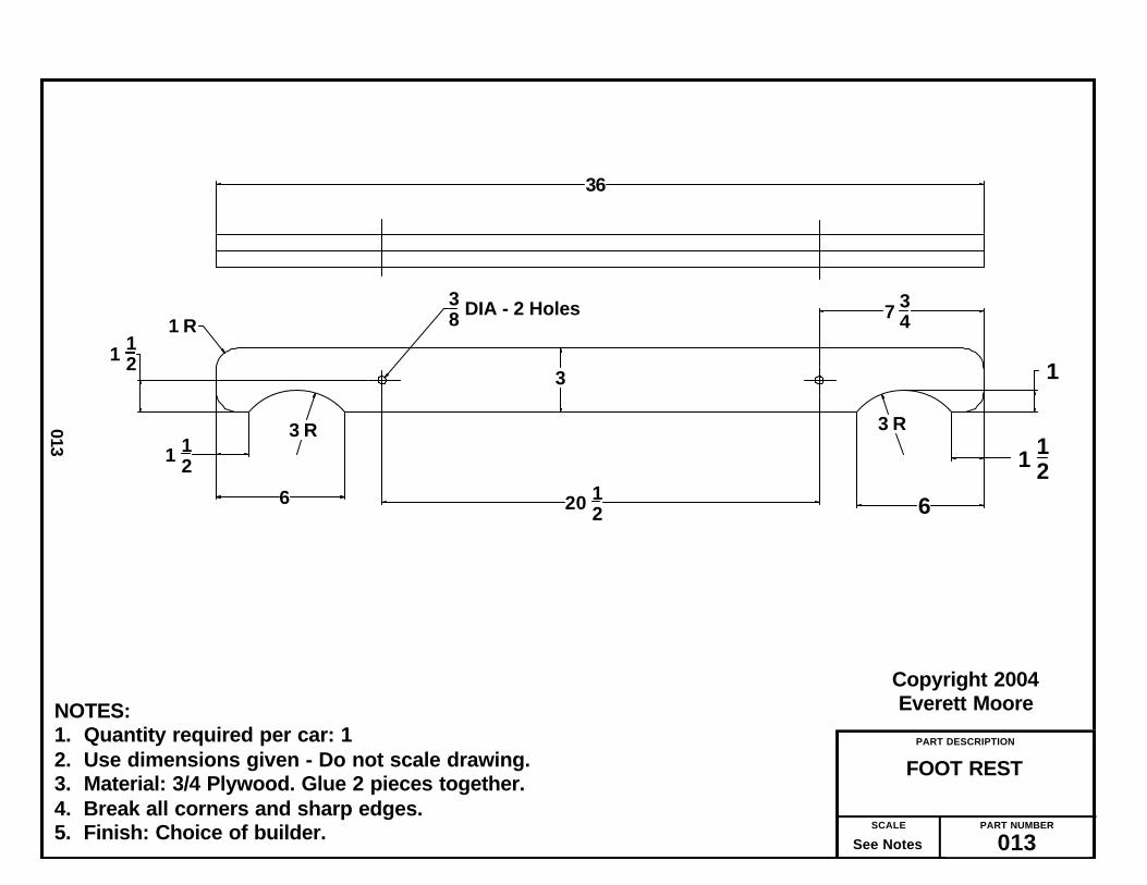
The foot rest is, likewise, made by gluingtogether two pieces of 3/4 inch plywood.
The fun piece is the steering shaft supportwhich, because of its shape, I call the “dogbone.” Like the front axle, you might want tosaw the 2 individual pieces before gluingtogether. A good drum sander is very usefulin the finishing of this part. Save the drillinguntil after the gluing is done.
While I didn’t specify any corner round-ing, I personally used a hand router and a1/4” round over bit to make a lot of edges“look pretty.”
I, also, spared a lot of little detail on thewood parts because I find most people withany degree of a home workshop will usuallyhave sufficient woodworking skills to suffice.
I recommend that any finished wood partbe left without paint at this time. You shouldcompletely finish, assemble and test driveyour car and only then disassemble andpaint.
_______________
6
The Making and Assembly Processes
A city version of the Cycle Car was madelater, using electric power for use in large
estates as personal transportation.It was call the “Red Bug.” We named ours
Red Bug, likewise.

PART DESCRIPTION
SHEET - 1PLYWOOD CUTTING
PART NUMBER
007SCALE
See Notes
Copyright 2004Everett Moore
7
NOTES:1. Quantity required per car: 12. Use dimensions given - Do not scale drawing.3. Material: 3/4 Plywood - full 4 x 8 sheet.4. Saw cut has been allowed for.
40 14
1534
front axle front axle front axle
rear axle rear axle
CHASSIS
seat support front
foot rest
foot rest
rear axle
seat support front
seat supportside
seat supportside
24
3
5 14
24 22 12 15 34 15 34
22 12
31 3/4 31 3/4 31 3/4 4 14
3 12
38 3
2 12
3 34
96
48
seat support botton

PART DESCRIPTION
SHEET - 2PLYWOOD CUTTING
PART NUMBER
008SCALE
See Notes
Copyright 2004Everett Moore
8
NOTES:1. Quantity required per car: 12. Use dimensions given - Do not scale drawing.3. Material: 1/4 Plywood - full sheet
3 12 ( X6 )
2 12
floor slat x 6
floor slat x 6
floor slat x 6
floor slat x 6
floor slat x 6
floor slat x 6

PART DESCRIPTION
SHEET - 3, SEATPLYWOOD CUTTING
PART NUMBER
009SCALE
See Notes
Copyright 2004Everett Moore
9
NOTES:1. Quantity required per car: 12. Use dimensions given - Do not scale drawing.3. Material: 3/4 Plywood
17.00
16.00
8.00
1.75
44.00
17.00 17.00
40.00
Back
Side Side
Bottom
Seat Back Strip
48.00
48.00

PART DESCRIPTION
TOP VIEWCHASSIS —
PART NUMBER
010SCALE
See Notes
Copyright 2004Everett Moore
010
NOTES:1. Quantity required per car: 12. Use dimensions given - Do not scale drawing.3. Material: 3/4” Plywood — Imitation Slats = 1/4” Plywood.4. All hole dia’s to be 3/8” except those marked “x” which are 1/4”.5. Some hole dia’s are called out on hole patterns.6. See text for more drilling instructions.7. Break all corners and sharp edges.8. Finish: Choice of builder.
1 12 R
8
15 12
20 27
31 12
48 12
72
4 14 7 78
10 12 2 6 38
2 116
2 116
18 R
10 516
10 516
3 58
3 316
2 14
6 58
1 14
14
Center Line Rear Axle
Center Line Front Axle
96
10 (ref) 1
1Hole Pattern "A"
4 R
Hole Pattern "B"
Hole Pattern "D" Hole Pattern "C"
Hole Pattern "E"
xx
x xx
xxx
xx
4 Center Line of Chassis
2
20 3 Center on groove
*
*
*
*
Dims marked with ( * ) apply to both front and rear axle mounting holes.
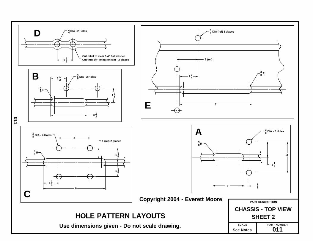
PART DESCRIPTION
SHEET 2CHASSIS - TOP VIEW
PART NUMBER
011SCALE
See Notes
Copyright 2004 - Everett Moore
011
HOLE PATTERN LAYOUTSUse dimensions given - Do not scale drawing.
38 DIA - 2 Holes
3
1 12
38 R
3 12
38 DIA - 2 Holes
38 R
1 38
3 12
1 12
3
6
38 R
1 38
1 38
38 DIA - 4 Holes
1 (ref) 2 places
1 12
14 DIA - 2 Holes
1 12
Cut relief to clear 1/4" flat washer Cut thru 1/4" imitation slat - 2 places 2 (ref)
7
38 R
38 DIA (ref) 3 places
1 34
A
B
C
D
E

PART DESCRIPTION
BLOCKBEARING MOUNTING
PART NUMBER
012SCALE
See Notes
Copyright 2004Everett Moore
012
NOTES:1. Quantity required per car: 22. Use dimensions given - Do not scale drawing.3. Material: 3/4 Plywood.4. Break all corners and sharp edges.5. Finish: Choice of builder.
78 4 14
6
1
338 DIA
2 HOLES3 PIECES OF 3/4 PLYWOODGLUED TOGETHER
APPROX. 2 1/4 INCHES
PART DESCRIPTION
FOOT REST
PART NUMBER
013SCALE
See Notes
Copyright 2004Everett Moore
013
NOTES:1. Quantity required per car: 12. Use dimensions given - Do not scale drawing.3. Material: 3/4 Plywood. Glue 2 pieces together.4. Break all corners and sharp edges.5. Finish: Choice of builder.
6
38 DIA - 2 Holes
36
1 12
1 R
3 R1 12
6
1
1 12
7 34
3
20 12
3 R

PART DESCRIPTION
SUB - ASSEMBLYFRONT AXLE
PART NUMBER
014SCALE
See Notes
Copyright 2004Everett Moore
014
NOTES:1. Quantity required per car: 12. Use dimensions given - Do not scale drawing.3. Material: 3/4 Plywood (3 pieces glued together)4. Break all corners and sharp edges.5. Finish: Choice of builder.
2 12
4 14
2 1478
1 18
Center Line of Chassis
10 516
2 116 2 1
16
10 516
2 14 78
38 DIA - 8 holes 2 14 (ref)
3 1316 both ends
13 1316 both ends
31 342 34 - 4 plcs
1" Dia. C'bore to depth shown - Typical 4 Places

PART DESCRIPTION
ASSEMBLYREAR AXLE
PART NUMBER
015SCALE
See Notes
Copyright 2004Everett Moore
015
NOTES:1. Quantity required per car: 12. Use dimensions given - Do not scale drawing.3. Material: 3/4 plywood (3 pieces), 1/4” plywood (1 piece) Cut to dims shown.
1” square x .120 wall steel tubing - 34.750 long4. Glue plywood pieces together as shown. When dry, epoxy steel tube in
to dimensions shown. Tube and plywood to be flush at top.5. Plywood thickness can vary. Therefore it may be necessary to touch up the
1” dado on the table saw to make a snug but loose fit between steel and wooden axle.
6. Break all corners and sharp edges.7. Finish: Choice of builder.
1 14 1 14 Center line
10 516
2 116 2 1
16
10 516
34 34
1 12
1 12 38 DIA - 4 holes
14 DIA - 12 holes
2 122 12
3 12
1 916 (ref - both ends)31 34
1 14 - Typical 6 places
Sq tube & plywood surfaces to be flush this entire surface34 78

PART DESCRIPTION
SUPPORTSTEERING SHAFT
PART NUMBER
016SCALE
See Notes
Copyright 2004Everett Moore
16
NOTES:1. Quantity required per car: 12. Use dimensions given - Do not scale drawing.3. Material: 2 pieces of 3/4 plywood glued together.4. Round over corners as shown.5. Finish: Choice of builder.
1 14
2
11 12
58 DIA
3
4 Places
34
Typical both ends
4 Holes
1 R12 R
1 12
2
5
14
1 14
38 DIA

PART DESCRIPTION
ASSEMBLYSEAT SUPPORT
PART NUMBER
017SCALE
See Notes
Copyright 2004Everett Moore
17
NOTES:1. Quantity required per car: 12. Use dimensions given - Do not scale drawing.3. Material: 3/4” Plywood.4. Glue & screw together.5. Finish: Choice of builder.
15 34
22 12
24
7 78
20
2 2 (REF)
38 DIA - 2 Holes
3 34
6
5 14
4 12

PART DESCRIPTION
SEAT ASSEMBLY
PART NUMBER
018SCALE
See Notes
Copyright 2004Everett Moore
18
NOTES:
1. Use dimensions shown. Do not scale drawing.2. Material: 3/4 in. plywood.3. Referring to this drawing and drawing XXX, cut two slots to accept corner brackets.4. Fit parts - glue - reinforce with screws and corner brackets.
15 34
40
4 R
4 R
80°
44
15
16
1 14
2
17
15
16 516
Front corner top viewTypical two places
3 12
o
1 R
8

PART DESCRIPTION
SEAT - REAR DETAIL
PART NUMBER
019SCALE
See Notes
Copyright 2004Everett Moore
19
NOTES:
1. Cut two slots as shown. Use router preferably. However, multiple holes can bedrilled and connected with jig saw. Slot should only be wide enough to acceptthe bracket. Prototype used 1/4 in.
2. Drill 1/4 dia holes thru seat back & arm rests and secure brackets with 1/4 - 20bolts, fender washers and nuts. Place nuts on outside.
Cut slot thru seat back to accept corner bracketboth sides
4 in corner reinforcing bracketfasten to rear of seat, extend thru slotfasten to outside of arm rest. ( 2 places )
Rear view of seat
Detail of seat back reinforcement

PART DESCRIPTION
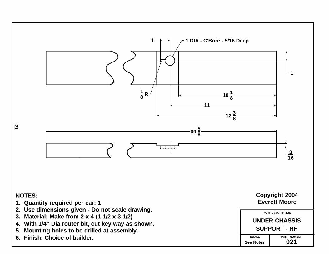
SUPPORT - LHUNDER CHASSIS
PART NUMBER
020SCALE
See Notes
Copyright 2004Everett Moore
20
NOTES:1. Quantity required per car: 12. Use dimensions given - Do not scale drawing.3. Material: Make from 2 x 4 (1 1/2 x 3 1/2)4. With 1/4” Dia router bit, cut key way as shown.5. Mounting holes to be drilled at assembly.6. Finish: Choice of builder.
10 1811
12 38
3 12
1 14
1 DIA - C'Bore - 5/16 Deep
69 58
1
18 R
316
PART DESCRIPTION
SUPPORT - RHUNDER CHASSIS
PART NUMBER
021SCALE
See Notes
Copyright 2004Everett Moore
21
NOTES:1. Quantity required per car: 12. Use dimensions given - Do not scale drawing.3. Material: Make from 2 x 4 (1 1/2 x 3 1/2)4. With 1/4” Dia router bit, cut key way as shown.5. Mounting holes to be drilled at assembly.6. Finish: Choice of builder.
1
10 1811
12 38
69 58
1 DIA - C'Bore - 5/16 Deep1
18 R
316

— Now Let’s Make Some Iron Filings —
If you haven’t already, you might want tocut the 1” square tube to required length andfinish the rear axle per drawing No. 015.
Be sure to align your chop saw so as to cutas near to 90 degrees as possible. I nevertrust the marks provided and prefer to use asquare to do this.
I recommend cutting all bar stock andangle parts to the required length at onetime. Next, remove any burrs and sharpedges with a hand file.
To layout the hole locations, you shouldhave a small bottle of layout blue. You needonly apply it to the approximate area wherethe holes will be. Accurately locate the holeswith a good square and scale. Scribe lineswith a scriber and center punch beforedrilling holes.
When all holes are drilled, using either abench grinder or hand grinder, form theradius’ called out on the drawings. These arenot critical and in some cases are more forappearance than anything else.
One of the more difficult parts will be thetwo hub mounting flanges, Drawing No. 034.Layout and scribe the hole locations withyour square and compass or use the card-board tool described in Drawing No. 035.
Using the appropriate tap drill, drill andthen tap holes per drawing. If you have neverused a tap before, do two things — 1) Use acutting fluid to lubricate the tap while cut -ting (I use WD-40) 2) Every couple or threeturns of the tap, stop and backup a turn tobreak the chip and free the tap again.
Don’t force the tap, back up, and go again.Nothing will make a grown man cry quickerthan breaking a tap flush with the work, usu-ally on the last hole of a nearly completedpart! Make an effort to start the tap perpen-dicular to the the part.
After completing drilling and tapping, allthat’s left to do is cutting the center hole. In
sticking with my criteria established at thebeginning, I did this without using a lathe. Ofcourse, if you have a lathe, by all means useit!
I used a 1-5/8” dia. metal cutting hole saw,cutting half way on one side and turning thepart over and finishing from the other side.
Since the hole could be a bit smaller, if youhave a 1-9/16” dia saw or want to use a flycutter, use it.
The only tapped holes remaining are onthe chain tightener anchor blocks and thetubular nuts (use in the steering shaft sup-port AKA “Dog Bone.”)
All the techniques of tapping used on theprevious parts, apply here, also.
While into tread cutting, you might aswell cut the threads on three parts madefrom round CRS. From your tap and die setchose the appropriate die and die stock (thehandle that holds the die) and, after cuttingthe rods to length, cut the threads per draw-ings No. 038 and 039.
The remaining metal work entails modify-ing a purchased part, such as cross drillingand pressing in a roll-pin, drill and tappingor, in one case, cutting threads with a die.
One part, the brake activator guide, PartNo. 041 requires drilling and tapping pluspressing in two bearings.
Other modifications are self-explanatoryas per the drawing.
Now is a good time to examine all yourparts by comparing them to the drawing.Remove any burrs found, de-grease and setaside for the initial assembly process.
Only after making sure that parts fit andfunction as intended, should they be de-greased, primed and painted with the finishof your choice.
_______________
22
The Making of Metal Parts

PART DESCRIPTION
MOUNTING BRACKETFRONT SPINDLE
PART NUMBER
023SCALE
See Notes
Copyright 2004Everett Moore
23
NOTES:1. Quantity required per car: 42. Use dimensions given - Do not scale drawing.3. Material: 1/4 X 1-1/2 Steel Bar Stock.4. Break all corners and sharp edges.5. Finish: Choice of builder.
.750
2.250
4.125
1 12 R
1 12
1116
5 58
.375 DIA (2)
.625 DIA

PART DESCRIPTION
SUPPORTDRIVE TRAIN
PART NUMBER
024SCALE
See Notes
Copyright 2004Everett Moore
24
NOTES:1. Quantity required per car: 22. Use dimensions given - Do not scale drawing.3. Material: 1” x 1” x .120 wall Square tube.4. Break all corners and sharp edges.5. Finish: Choice of builder.
25
1
932 DIA
12
Note: Used only if excessive flexing of the plywood chassis in the area of engine mount and jack shaftis experienced. Install by raising engine (PP 215) and engine mounting plate (PP 250) and slidingthe two supports between wood chassis and mounting plate. Place as far apart as possible while in contact with engine mounting bolts. Secure supports at front with 1/4” hardware. This may in-crease the length of #35 roller chain required between torque converter and jack-shaft.

PART DESCRIPTION
BASE PLATECHAIN TIGHTENER
PART NUMBER
025SCALE
See Notes
Copyright 2004Everett Moore
25
NOTES:1. Quantity required per car: 22. Use dimensions given - Do not scale drawing.3. Material: 3/16 X 2” Bar Stock.4. Break all corners and sharp edges.5. Finish: Choice of builder.
1.375
516
5161 784.250
7
.375 DIA - 2 Holes
.250 DIA - 2 Holes
1
2 (ref)

PART DESCRIPTION
A & BWASHER PLATES
PART NUMBER
026SCALE
See Notes
Copyright 2004Everett Moore
26
NOTES:1. Quantity required per car: See notation on drawing.2. Use dimensions given - Do not scale drawing.3. Material: 1/8 x 1 Bar stock.4. Break all corners and sharp edges.5. Finish: Choice of builder.
38 1 14
2
932 DIA
5
12
1
1
Plate A - Qty = 4
Plate B - Qty = 2
12
1516 3 18
38 DIA

PART DESCRIPTION
BRAKE LEVER
PART NUMBER
027SCALE
See Notes
Copyright 2004Everett Moore
27
NOTES:1. Quantity required per car: 12. Use dimensions given - Do not scale drawing.3. Material: 1/4 X 1 Bar Stock.4. Drill & bend as indicated.5. Break all corners and sharp edges.6. Finish: Choice of builder.
16(ref)
.250 DIA
3
12 R
19 12.312 DIA
Both ends
10°
5

PART DESCRIPTION
PULLEY MTG. BKT.CENTER BRAKE
PART NUMBER
028SCALE
See Notes
Copyright 2004Everett Moore
28
NOTES:1. Quantity required per car: 12. Use dimensions given - Do not scale drawing.3. Material: 1/8 X 1- 1/2 steel bar stock.4. Break all corners and sharp edges.5. Finish: Choice of builder.
7
4.001 12
.250 DIA2 Holes
34
1 12

PART DESCRIPTION
PULLEY MTG. BKT.OUTBOARD BRAKE
PART NUMBER
029SCALE
See Notes
Copyright 2004Everett Moore
29
NOTES:1. Quantity required per car: 1 Left Hand & 1 Right Hand.2. Use dimensions given - Do not scale drawing.3. Material: 1/8 X 1- 1/2 Steel Bar Stock4. Twist bend as shown to allow brake cable to go under chassis board.4. Break all corners and sharp edges.5. Finish: Choice of builder.
1 12 4.50 6.00
13
11 12
12°
34
1 12
.250 DIA
.375 DIA2 Holes
Twisting bend to be within this area
LH as shown (Qty 1)
18 R
RH to be mirrow image (Qty 1)
A =
B =

PART DESCRIPTION
MOUNTING BRACKETBRAKE LEVER
PART NUMBER
030SCALE
See Notes
Copyright 2004Everett Moore
30
NOTES:1. Quantity required per car: 22. Use dimensions given - Do not scale drawing.3. Material: 3/16 X 2 X 2 Angle.4. Break all corners and sharp edges.5. Finish: Choice of builder.
34 2 12
2
12 3
4
2
21
1 12
1
316 (ref)
.250 DIA
.312 DIA
.375 DIA - 2 Holes
18 R
2 HOLES
12 R

PART DESCRIPTION
MOUNTING BKT - LHBRAKE ANCHOR
PART NUMBER
031SCALE
See Notes
Copyright 2005Everett Moore
31
NOTES:1. Quantity required per car: 12. Use dimensions given - Do not scale drawing.3. Material: 3/16 X 2 X 2 Angle.4. Break all corners and sharp edges.5. Finish: Choice of builder.
.375 DIA
1 12
1
22
3 HOLES 5
5 34
78
12
14 R
12 R

PART DESCRIPTION
MOUNTING BKT - RHBRAKE ANCHOR
PART NUMBER
032SCALE
See Notes
Copyright 2005Everett Moore
32
NOTES:1. Quantity required per car: 12. Use dimensions given - Do not scale drawing.3. Material: 3/16 X 2 X 2 angle4. Break all corners and sharp edges.5. Finish: Choice of builder.
.375 DIA
3 HOLES
1 12
121
2
2
78
5
5 34
14 R 1
2 R

PART DESCRIPTION
BRACKETTHROTTLE MOUNTING
PART NUMBER
033SCALE
See Notes
Copyright 2004Everett Moore
33
NOTES:1. Quantity required per car: 12. Use dimensions given - Do not scale drawing.3. Material: 3/16 - 2 x 3 Angle or make from larger angle.4. Break all corners and sharp edges.5. Finish: Choice of builder.
1
2
2
4
2
3
12
3
.375 DIA.312 DIA
12 R
14 R
2 Holes

PART DESCRIPTION
FLANGE - ALTERNATIVEHUB MOUNTING
PART NUMBER
034SCALE
See Notes
Copyright 2004Everett Moore
34
NOTES:1. Quantity required per car: 22. Use dimensions given - Do not scale drawing.3. Material: See drawing callout.4. Break all corners and sharp edges.5. Finish: Choice of builder.
Make from 3 1/2" Dia. Aluminum discMcMaster-Carr No. 9035K17 - PP 248
5/16 x 24 UNF4 holes
2.812 DIA
2.000 DIA
1/4 x 28 UNF4 holes
1-5/8 DIA
3-1/2 DIA (ref)
.50 (REF)

PART DESCRIPTION
WHEEL/FLANGE DRILLCARDBOARD TOOL
PART NUMBER
035SCALE
See Notes
Copyright 2004Everett Moore
35
NOTES:1. Quantity required per car: 12. Use dimensions given - Do not scale drawing.3. Material: Cardboard such as on back of writing tablets, poster board, etc.4. Cut stack of small disks to be snug fit in wheel bearing hole. (approx 1.375).5. Glue stack of small disks concentrically on large disk. This stack must be
sufficient to firmly locate tool in wheel hub.6. Make small pin hole at intersection of all 8 hole locations.
3 12 DIA
2 1316 DIA
1 1332 R
2 DIA
1 R
1 1132 DIA
*
Location of pin holesTypical 8 places

PART DESCRIPTION
ANCHOR BLOCKCHAIN TIGHTENER
PART NUMBER
036SCALE
See Notes
Copyright 2004Everett Moore
36
NOTES:1. Quantity required per car: 22. Use dimensions given - Do not scale drawing.3. Material: 5/8” Sq. Bar Stock or Key Stock.4. Break all corners and sharp edges.5. Finish: Choice of builder.
1/4 - 28 UNF - 3 Holes
1.375
516
58
58
516
2
1

PART DESCRIPTION
TUBULAR NUT
PART NUMBER
037SCALE
See Notes
Copyright 2004Everett Moore
37
NOTES:1. Quantity required per car: 42. Use dimensions given - Do not scale drawing.3. Material: 5/8 Dia CRS4. Break all corners and sharp edges.5. Finish: Choice of builder.
58 DIA
5/16 - 24 UNF
34
1 12

PART DESCRIPTION
SHAFTBRAKE ACTIVATOR
PART NUMBER
038SCALE
See Notes
Copyright 2004Everett Moore
38
NOTES:1. Quantity required per car: 12. Use dimensions given - Do not scale drawing.3. Material: .250 Dia. Cold Rolled Steel (CRS).4. Break all corners and sharp edges.5. Finish: Choice of builder.
8.00
1 12 1
1/4 - 28 UNF - Both ends - Min. full thread as shown

PART DESCRIPTION
TIE RODS - A & B
PART NUMBER
039SCALE
See Notes
Copyright 2004Everett Moore
39
NOTES:1. Quantity required per car: 1 “A” & 1 “B”2. Use dimensions given - Do not scale drawing.3. Material: Per drawing callout.4. Break all corners and sharp edges.5. Finish: Choice of builder.6. Assemble each Tie Rod with lock nut and ball end on each end. Screw on
far enough to keep together as a unit. Do not tighten until final assembly.
Make from 3/8 dia CRS
3/8 - 24 UNF - Min 1-1/2" full thd - both ends
3/8 - 24 Nut (4 req"d)
Tie Rod "A" = 7 in. Long
Tie Rod "B" = 23 3/8 long
3/8 - 24 Ball end - No. PP 203 (4 req'd)
PART DESCRIPTION
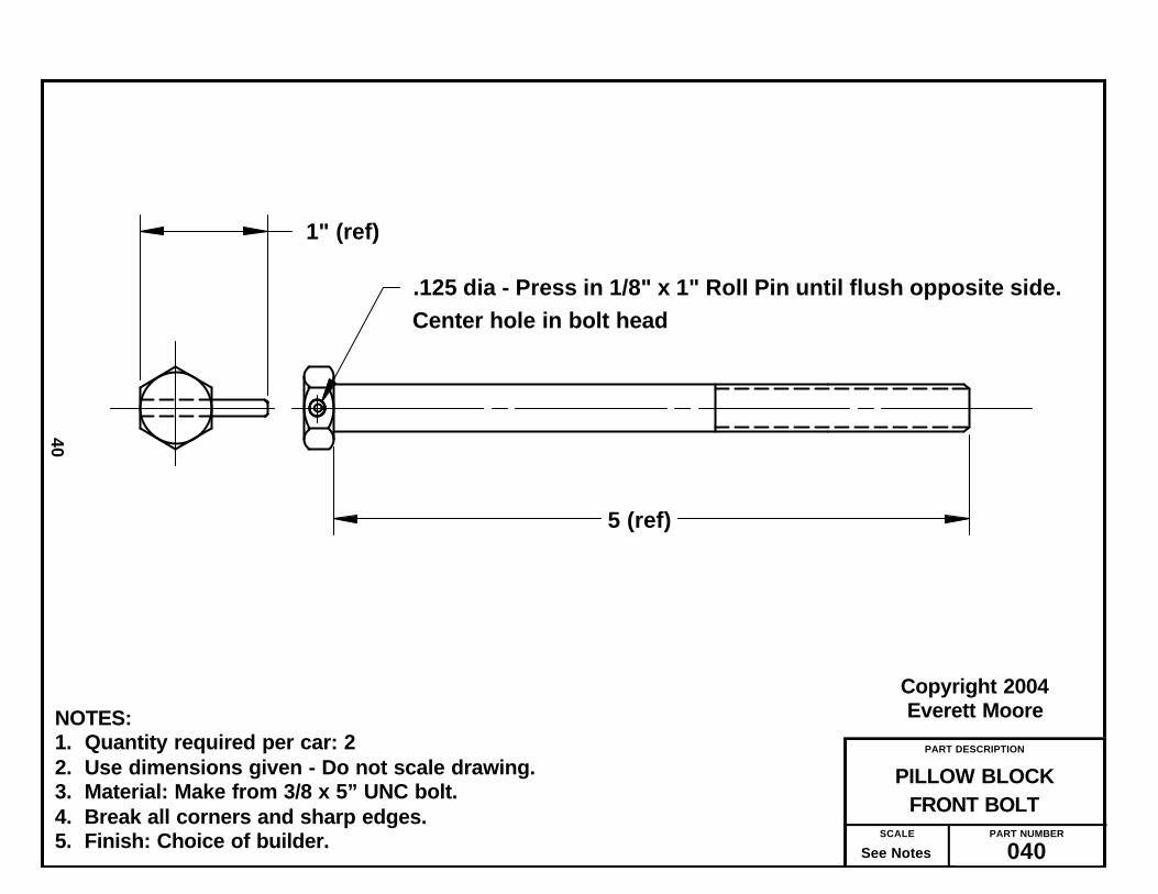
FRONT BOLTPILLOW BLOCK
PART NUMBER
040SCALE
See Notes
Copyright 2004Everett Moore
40
NOTES:1. Quantity required per car: 22. Use dimensions given - Do not scale drawing.3. Material: Make from 3/8 x 5” UNC bolt.4. Break all corners and sharp edges.5. Finish: Choice of builder.
.125 dia - Press in 1/8" x 1" Roll Pin until flush opposite side.
1" (ref)
5 (ref)
Center hole in bolt head

PART DESCRIPTION
GUIDEBRAKE ACTIVATOR
PART NUMBER
041SCALE
See Notes
Copyright 2004Everett Moore
41
NOTES:1. Quantity required per car: 12. Use dimensions given - Do not scale drawing.3. Material: Per drawing callout. The builder has lattitude to utilize what ever
is on hand to build this guide. 4. Break all corners and sharp edges.5. Press bearings in flush with flange (both ends). The .250 hole thru bearings
must be aligned and free for movement of activator shaft. This may require running drill through holes after assembly.
6. Finish: Choice of builder.
58
34 1 12
3" (ref)
1 14 (ref) 12
14 (ref)
1/4 - 28 UNF - 2 holes
.375 DIA - thru both ends
1 (ref)
PP 242
PP 243 (2)
14 DIA
See notes
PART DESCRIPTION
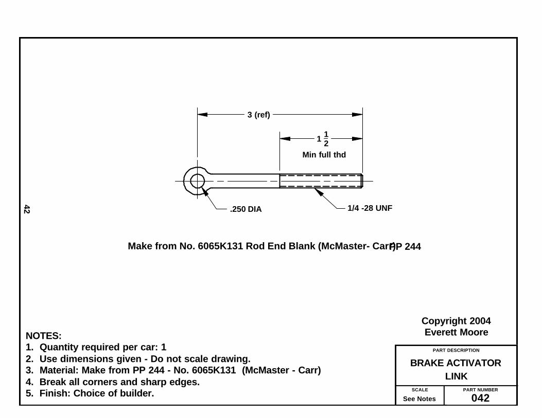
LINKBRAKE ACTIVATOR
PART NUMBER
042SCALE
See Notes
Copyright 2004Everett Moore
42
NOTES:1. Quantity required per car: 12. Use dimensions given - Do not scale drawing.3. Material: Make from PP 244 - No. 6065K131 (McMaster - Carr)4. Break all corners and sharp edges.5. Finish: Choice of builder.
Make from No. 6065K131 Rod End Blank (McMaster- Carr)PP 244
.250 DIA 1/4 -28 UNF
1 12Min full thd
3 (ref)

PART DESCRIPTION
ANCHOR BOLTBRAKE BAND
PART NUMBER
043SCALE
See Notes
Copyright 2004Everett Moore
43
NOTES:1. Quantity required per car: 22. Use dimensions given - Do not scale drawing.3. Material: Make from 3/8 x 24 UNF bolt.4. Cross drill .125 dia as shown.5. Break all corners and sharp edges.6. Press roll pin thru bolt flush with opposite side.7. Finish: Choice of builder.
2 14
12
1/8 x 3/4 Roll pin1
1 in. before threads
PART DESCRIPTION
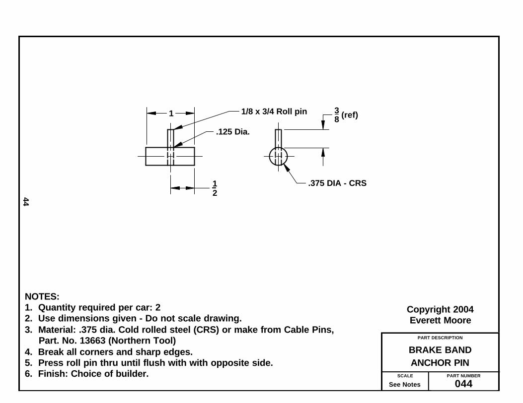
ANCHOR PINBRAKE BAND
PART NUMBER
044SCALE
See Notes
Copyright 2004Everett Moore
44
NOTES:1. Quantity required per car: 22. Use dimensions given - Do not scale drawing.3. Material: .375 dia. Cold rolled steel (CRS) or make from Cable Pins,
Part. No. 13663 (Northern Tool)4. Break all corners and sharp edges.5. Press roll pin thru until flush with with opposite side.6. Finish: Choice of builder.
12
1/8 x 3/4 Roll pin1
.375 DIA - CRS
38 (ref)
.125 Dia.

PART DESCRIPTION
MODIFICATIONREAR HUB
PART NUMBER
045SCALE
See Notes
Copyright 2004Everett Moore
45
NOTES:1. Quantity required per car: 22. Material: Per callout on drawing.3. Carefully remove bearing from one side.4. Use dimensions given - Do not scale drawing.5. Remove burrs after drilling.6. Finish: Paint metal exposed by drilling. Color: Choice of builder.
on 2.000 dia BC4 holes, evenly spaced
Only hub is shown for clarity.
17/64 Dia.
Rear Wheel (Purchased Part No. 206)

PART DESCRIPTION
MODIFICATIONTHROTTLE PEDAL
PART NUMBER
046SCALE
See Notes
Copyright 2004Everett Moore
46
NOTES:1. Quantity required per car: 12. Use dimensions given - Do not scale drawing.3. Material: Make from Azusa Part No. AZ1806 PP 2454. Break all corners and sharp edges.5. Finish: It’s Zink plated - only touch up raw metal from alteration - any color.
Straighten shank
Remove & discard threaded pin Cut tang off as shown
5/16 Dia (ref)
732
332 DIA
14
PP 245
1.75 (ref)

PART DESCRIPTION
CLAMP MODIFICATIONTHROTTLE CONDUIT
PART NUMBER
047SCALE
See Notes
Copyright 2004Everett Moore
47
NOTES:1. Quantity required per car: 42. Use dimensions given - Do not scale drawing.3. Material: Make from purchased part.4. Bend tab as shown. This allows sufficient contact with wood to hold in
place.5. Finish: None - already plated.
Make from PP 239
Bend tab up as shown

PART DESCRIPTION
A & BSTEERING SHAFT
PART NUMBER
048SCALE
See Notes
Copyright 2004Everett Moore
48
NOTES:1. Quantity required per car: 1 each.2. Use dimensions given - Do not scale drawing.3. Material: Make from purchased parts per drawing callout.4. Break all corners and sharp edges.5. Finish: Choice of builder.
SHAFT "A" (1 Req'd)
SHAFT "B" (1 Req'd)
PP 232
Make from PP 233
15 12
24 (REF)

You will find that there are some partsthat can best be assembled as a sub-assemblyand then, be attached to the final assembly asa unit.
A perfect example of this is the brake acti-vator assembly as shown on drawing No. 050.
This unit is adjusted after final assembly,to allow proper function of braking mecha-nism. You will note how the brake cable isthreaded through the pulley of this sub-assembly.
This simple mechanism provides equalapplication of braking force to both rearwheel drums.
The next sub-assembly will be the twochain tighteners per drawing No. 057. Theassembly is straight forward with the use of1/4-28 UNF hardware per call out on draw-ing.
An all-thread bolt is made by the jammingof 2 hex nuts on one end.
The next two sub-assemblies are a bitmore difficult. Referring to drawing No. 052,you will see how the adapter, Part No. 034 isattached to a rear wheel. While we onlypower the right wheel, both wheels havebrake drums and require both rear wheels tohave this adapter attached.
Originally, we fastened the adapter andwheel with 1/4-28 socket-head cap screwsand split lockwasher. However, after severalmiles of parade driving, this loosened up onthe driven wheel.
Therefore, we now recommend that inaddition to the lockwasher, the threads becoated with LocTite (Red), making a semi-permanent assembly.
The inner bearing of the wheel had to beremoved for the drilling of the four holes asshown in drawing No. 045. The bearing is notreplaced until after the mounting flange hasbeen attached.
Doing the above described assemblyrequires working in very tight quarters. Along, ball end allen wrench is used to insertand turn the Allen Head screws from theopening in the opposite bearing.
After applying LocTite, tighten all fourscrews as tight as you can get them just shortof breaking the ball end off your wrench.Hopefully, this is the last time you have to dothis.
With the two rear wheels thus done, youmight as well proceed to finishing up the rearwheels by attaching the sprockets and brakedrums per drawing No. 053.
Having an unused sprocket on the leftrear wheel serves a purpose. At first we hada large 1/8 thick disc between the left wheeland the brake drum to assure the brake bandremaining in correct position.
Actually, we learned that making this discwithout a lathe was difficult and, if done by amachine shop, would cost more that an extrasprocket. Also, if you wanted to add a differ-ential in place of the jack shaft, the drivensprocket is there waiting for you.
Meanwhile, it serves the purpose of keep-ing the brake band in place. It, also, serves asa conversation piece. When someone, whilelooking your car over, asks what that sprock-et is for, tell them it is the sending or triggerwheel for your anti-skid braking system!
The front axle can either be sub-assem-bled separately or after it is attached to thechassis board. I prefer the latter. In eithercase it is depicted on drawing No. 054.
The jack shaft can, likewise, be looselyassembled as a sub-assembly. See drawingNo. 061 for reference.
_______________
49
The Sub-Assembly Process

PART DESCRIPTION
ASSEMBLYBRAKE ACTIVATOR
PART NUMBER
050SCALE
See Notes
Copyright 2004Everett Moore
50
NOTES:1. Quantity required per car: 12. Use dimensions given - Do not scale drawing.3. Material: Per drawing callout4. Finish: Choice of builder.5. A compression spring can be added to area indicated to aid returning of
brake to off position. (Optional)5. Final adjust of this assembly is done at final assembly.
1/4- 28 Hex nut (3)
Note: It may be necessaryto file clevis in this areafor free turning of pulley
Spring optional
PP 235 (1)
PP 214 (3) PP 240 (3) PP 241 (3)
PP 214 (ref)
PP214 (ref)
041
038 042

PART DESCRIPTION
SUB-ASSEMBLYCHAIN TIGHTENER
PART NUMBER
051SCALE
See Notes
Copyright 2004Everett Moore
51
NOTES:1. Quantity required per car: 22. Use dimensions given - Do not scale drawing.3. Material: Per drawing call outs.4. Break all corners and sharp edges.5. Finish: Previously finished.
1/4 - 28 All Thread Rod - 2 3/4" Lg.
Make head by jamming 2 hex nutswith J B Weld in threads.
1/4 - 28 Hex Nut
1/4 - 28 x 3/4" C'screw & L'washer (2)
036
025

PART DESCRIPTION
SUB-ASSEMBLYREAR WHEEL - FLANGE
PART NUMBER
052SCALE
See Notes
Copyright 2004Everett Moore
52
NOTES:1. Quantity required per car: 22. Material: Per drawing callout. 3. Apply LocTite (Red) to threads.4. Re-install bearing removed when modifying hub. Use new bearing if
original was damaged.5. Finish: Finished prior to assembly.
1/4 X 28 - 5/8 Long Socket Hd Capscrew (4 req'd)
Only hub is shown for clarity.Part No. 045
Part No. 034
1/4 Lock Washer (4 req'd) - Apply LocTite (Red) to threads.

PART DESCRIPTION
SPROCKET & DRUM REAR WHEEL ASS’Y -
PART NUMBER
053SCALE
See Notes
Copyright 2004Everett Moore
53
NOTES:1. Quantity required per car: 22. Material: Per callout on drawing.3. Finish: Parts are pre-finished at assembly
5/16 x 24 UNF - 7/8 Long Socket Head C'Screw5/16 Lock Washer4 each req'd
Sprocket - PP No. 218 Northern # 1363 (54 tooth - 41 pitch)
Brake Drum - PP No. 223Northern # 1366 Wheel Sub-Assembly Part No. 052

PART DESCRIPTION
ASSEMBLYFRONT AXLE
PART NUMBER
054SCALE
See Notes
Copyright 2004Everett Moore
54
NOTES:1. Quantity required per car: 12. Use dimensions given - Do not scale drawing.3. Material: Per drawing callout.4. Break all corners and sharp edges.5. Finish: Parts to be finished before assembly.6. Add 3/8 fender washers to lower spindle brackets as necessary to obtain
proper fit of spindle.
PP 202 PP 228 (2)
PP 201 PP 228 (2)
023 (4) 014
Adjust spacing between brackets, if needed, by placing large, fender washers between lower brackets and wood.

— Lets Build a Car —
I recommend that, before painting any-thing, you completely assemble your car andtest drive it. Don’t use lock nuts this time —merely use regular hex nuts and lock wash-ers. Trailer it to some area where you cansafely drive it around a bit. If you have aproblem, now is the time to find out.
Once you’re satisfied, completely disas-semble, clean all the metal parts withAcetone or other good de-greaser and paintthe color of your choice. My car was finishedwith gloss black on the metal parts andbright red on the wood.
On the final assembly, use nylon lock nutsevery where possible. Where not possible, useLocTite (blue). There’s a lot of unfelt vibra-tion that can loosen hardware and ruin theentire parade for you.
I have not specified the exact lengths andsizes of most hardware as it should be selfevident. When attaching parts to wood, thewood tends to crush under the load of tight -ening the bolts. Hence, the generous use oflarge, fender washers is advised. Build all thesub-assemblies first. Follow the instructionson the specific drawing.
Now, with the chassis board upside downon saw horses, assemble the front and rearaxles, and proceed with the attachment of allparts noted on Drawing No. 058.
From the pictures to the right you see anamazing amount of parts and hardware uti-lized in this “simple” car!
You will use quite a bit of the hardwarewhile working on the underside. However, beprepared to “box it up” when it becomes nec-essary to turn it over and assemble on the topside.
Attach both front and rear axles at thistime. Referring to drawing No. 058 and pho-tos on page 56, attach as many of the partsshown on the next page as possible. Notingthe direction of the bolts you made with the
55
The Assembly Process
The upside down chassis board makes anexcellent place to pile parts and hardware -until you need to assemble from the topside!

56
Photo No 1 - Throttle cable routing underbrake equalizer assemble. Note how thecable is held in place with 3 clamps, Part No.047.
Photo No. 2 - Throttle cable makes its exit totop side through hole drilled at an angle thatwill prevent any restriction to throttle wiremovement. Held in place with clamp, PartNo. 047.
Photo 3 - Attachment of throttle wire to footpedal with “Z” bend in end of wire. Note thecable being held with another clamp No.047. An extension spring has been added toassist throttle returning to idle.
Photo No. 4 - This shot shows the brakeequalizer and how the brake cable is thread-ed to reach the outer puller and finally tobrake band.
Photo No. 5 - Detail of how throttle wire ter-minates at engine. A modified “Z” bendmatches the existing hole in throttle armwhile Clamp, part No. PP 239 attaches toexisting threaded engine hole with 10-32 x1/2 socket head cap screw. An additionalspring added to assist return to idle.
Photo No. 6 - Throttle cable emerges fromjust behind seat support.

roll-pin protruding from the head, installthrough proper hole in both outboard brakepulley mtg. brackets, Part Nos.029A and029B. Leave bolt loose at this time. With theroll-pins pointing forward, the two chassissupports, Part Nos.020 and 021 can be posi-tioned in place. The Foot rest, part No. 013can be installed from the opposite side andloosely bolted in place.
Continue to refer to assembly drawing No.058, which shows the proper location of mostparts under your car.
While the tie rod assemblies are shown onthis drawing, it is best to wait until the steer-ing shaft, part No.048A has been installedbefore attaching the tie rods.
When you are satisfied that the bottommounted parts have been installed as far aspossible, turn the chassis over, revealing thetop side (with slats). You can now mount theseat support. Note: while not called out ondrawing, I placed four large diameter rubberwashers under the seat support (about 2” infrom the four corners. When the mountingbolts are tightened, the rubber washers arecaptivated. Since the chassis flexes underchanging terrain, this allows some “float”between the two parts.
Make sure the seat support does not inter-fere with the throttle cable. Check to insurefree movement of the throttle wire.
Before mounting the jack shaft assembly,it is best to semi-assemble it before hand.Leave all setscrews loose. Refer to Dwg.062.
You should have a bolt protruding up onboth sides of the chassis. Drop both bearingsupport blocks, part Nos 012 over these holes.Next install the chain tension adjusters, partNo.051 over the protruding bolt. Refer todrawing Nos 062 & 063 for detail and orien-tation of the adjusters.
You can now carefully lower the jack shaftassembly onto the support blocks as shownon assembly drawings No.059 and No.062.Install the second bolt up through the chassissupport, chassis, bearing block, chainadjuster and through the elongated hole inthe pillow block. Use as many heavy, flat
washers under the nuts securing the pillowblocks, as possible.
Referring to drawing No.062, locate thelarge sprocket that connects to the engine, inthe center of the clearance slot cut for it. Donot tighten any sets screws yet.
Before continuing with the jack shaft, it isnecessary to mount the rear wheels.However, this is even a better time to mountthe brake band anchor bolts (with the roll-pin). See the brake band installation draw-ing No.064 for details.
To install engine, refer to drawing No. 059and 060. On the prototype the engine wasbolted directly to the chassis board with anengine mounting plate, No. PP 250 separat-ing the engine from the wood.
Actual tests indicated that addition stiff-ness was needed. Therefore, engine supports,drawings No. XXX and XXX were added.They are installed between the wood chassisboard and the engine mounting plate.
You will note, by observing the picture onpage 5, how a 1/4” pipe nipple and elbow wasused to extend the engine’s oil drain plug rearand downward, to enable easy oil changes.
57

PART DESCRIPTION
BOTTOM VIEWCHASSIS ASSEMBLY -
PART NUMBER
058SCALE
See Notes
Copyright 2004Everett Moore
58
NOTES:1. Quantity required per car: 12. Parts locate per previously drilled holes.3. Material: Per drawing callout.4. Assemble per intructions in text.
PP 236
054
039A
039B
010
023 046
PP 238 PP 239
047
020
050
021
028 PP 235 (2)
029A PP 235
029B PP 235
040 Roll pin
pointing forward
015 026A
026A
026B (2)
040 Roll pin pointing forward

PART DESCRIPTION
TOP VIEWCHASSIS ASSEMBLY -
PART NUMBER
059SCALE
See Notes
Copyright 2004Everett Moore
59
NOTES:1. Quantity required per car: 12. Parts locate per previously drilled holes.3. Material: Per drawing callout.4. Assemble per intructions in text.5. Slip bicycle handlebar grip onto brake lever to improve grip.
013 027 (See Notes)
030 (2)
017
065
215
216
Attach brake actuator ass'y (below)with 1/4-28 x 1" capscrews & fenderwashers. Bolt head must not interferwith seat support (017).Secure with LocTite (Blue)

PART DESCRIPTION
SIDE VIEWCHASSIS ASSEMBLY
PART NUMBER
060SCALE
See Notes
Copyright 2004Everett Moore
60
NOTES:1. Dis-assemble pillow blocks No. PP 204 and re-assemble with oil cup out
side instead of top hole. This will allow extreme movement of bearingnecessary to match angle of steering shaft.
2. Position the steering shaft to clear front axle by 1/4” and secure in placewith Collars PP 212 and Bearings PP 229.
3. Attach seat to support with 2-1/2” removable pin hinges (2)
Direction of throttle cable
048A PP 234
048B PP 226 PP 227
016 037 (4)
018
For detail see drawing 061
PP 212 (2) PP 229 (2)
PP 204 (2)
Mtg. flange included with 048B
067
068
See notes
14 (ref)

PART DESCRIPTION
SHAFT ASS’Y DETAILSTIE ROD - STEERING
PART NUMBER
061SCALE
See Notes
Copyright 2004Everett Moore
61
NOTES:1. Assemble as shown.2. End of steering shaft to be 1/4” from front axle.2. Use shim washers as shown to premit maximum tie rod travel.3. Secure nuts with LocTite (blue)
PP XXX (typical)
PP XXX (typical)
Apply LocTite (Blue) 2 places
PP 210 (typical)
PP 211 (typical)
Apply LocTite (Blue) 2 places
1/4

PART DESCRIPTION
ASSEMBLYJACKSHAFT
PART NUMBER
062SCALE
See Notes
Copyright 2004Everett Moore
62
NOTES:1. Quantity required per car: 12. Use dimensions given - Do not scale drawing.3. Material: Per drawing call out.4. Break all corners and sharp edges.5. Finish: n/a
012 PP 225 (Cut to dimension shown) 012
PP 205 (2)
PP 213
051 (2)
PP 220
PP 219
PP 213
PP 217
PP 213
PP 213
30

PART DESCRIPTION
INSTALLATIONCHAIN TIGHTENER
PART NUMBER
063SCALE
See Notes
Copyright 2004Everett Moore
63
NOTES:1. Quantity required per car: Typical 2 places.2. Balance of Jack shaft assembly shown on drawing No. 062.3. Material: Per drawing callout.
Front of car
Grease fitting to rear
3/8 Lock Nut& double flat washers
PP 205
PP 225 (ref)
057 (ref)
012 (ref)

PART DESCRIPTION
INSTALLATIONBRAKE BAND
PART NUMBER
064SCALE
See Notes
Copyright 2005Everett Moore
64
NOTES:1. Quantity required per car: 2 (left and right)2. Loosely assemble anchor bolt (043) at this stage. Final adjustment are
made to it and brake cable after rear wheels are mounted.3. Secure brake cable with standard clamp from hardware store.4. Roll-pins of parts 043 and 044 are positioned approximately as shown.
PP 224 (2)
031 (Left ) 032 (Right )
043
044

PART DESCRIPTION
DETAILSAXLE - HUBCAP
PART NUMBER
065SCALE
See Notes
Copyright 2004Everett Moore
65
NOTES:
1. Use dimensions shown. Do not scale drawing.2. Axle = 3/4 dia CRS cut oversize (48”) - Push axle thru axle tube on frame - Install shim
washers and 1 wheel as show above - Install 1 hub cap, cross drill, install cotterpin - Install shim washers and 2nd wheel - Allowing extra length for hub cap,cut off - Install hub cap - cross drill - Install 2nd cotter pin.
3. Add or remove 1/32 shim washers to allow wheels to turn freely without excess-sive end play.
Make from 1/2 in pipe capDrill out to 3/4 dia. - cross drill 5/32 dia.
Attach entire assembly to axle with 5/32 cotter pin
See notes about axle length
Suggest using 2 at first.
PP 246 - 1/32 shim washer (as needed)
PP 247 - 1/8 shim washer (as needed)PP 206Wheel

PART DESCRIPTION
INSTALLATION DWG.DRIVE TRAIN SUPPORT
PART NUMBER
066SCALE
See Notes
Copyright 2004Everett Moore
66
NOTES:1. Quantity per car: 2 (If required)2. Material: Per drawing call out.
024 (2)

PART DESCRIPTION
SEAT CUSHION BASE
PART NUMBER
067SCALE
See Notes
Copyright 2004Everett Moore
67
NOTES:1. Quantity required per car: 12. Use dimensions given - Do not scale drawing.3. Material: 1/2 inch plywood - 1/4 - 20 x 5/16 “T” nuts (4) - PP 2494. Break all corners and sharp edges.5. Finish: None.6. Suggest using 2 in. of foam covered with appropriate upholstery material
stretched tight and stapled in back. Be sure and not cover up the mountingholes. Alternate: Take to an upholstery shop and let them cover it.
Section A - A 4:1
7 14 21
35 12
AA
11
14
1 12
5/16 dia C'bore 1" dia 1/16 deep
Press 1/4 - 20 "T" nut flushTypical 4 places

PART DESCRIPTION
CUSHION BASESEAT BACK
PART NUMBER
068SCALE
See Notes
Copyright 2004Everett Moore
68
NOTES:1. Quantity required per car: 12. Use dimensions given - Do not scale drawing.3. Material: 1/2 inch plywood - 1/4 - 20 x 5/16 “T” nuts (3) - PP 2494. Break all corners and sharp edges.5. Finish: None.6. Suggest using 2 in. of foam covered with appropriate upholstery material
stretched tight and stapled in back. Be sure and not cover up the mountingholes. Alternate: Take to an upholstery shop and let them cover it.
Section A - A 4:1
Press 1/4 - 20 "T" nut flush
AA
Typical 3 places
7 12
3 34
32
16
5 12
43
4 R
1 R
5/16 dia C'bore 3/4" dia 1/16 deep

Vendor Code = FB Foley-BelsawP.O. Box 419593Kansas City, Mo 641411-800-821-3452
Vendor Code = G * W. W. Grainger, Inc.Website: www.grainger.com
Vendor Code = McC ** McMaster-CarrWebsite: www.mcmaster.com
Vendor Code = MS Manufacturer’s SupplyP.O. Box 167Dorchester, WI 544251-800-826-8563Website: www.mfgsupply.com
Vendor Code = NT Northern Tool & Equipment1-800-556-7885Website: www.NorthernTool.com
Vendor Code = SEW Small Engine Warehouse765-768-6725Website: www.smallenginewarehouse.com
Vendor Code = GKG Go-Kart Galaxy1-903-340-1965Website: www.gokartgalaxy.com
Vendor Code = AS Aircraft Spruce & Specialty Co.1-877-477-7823Website: http://www.aircraftspruce.com
* W. W. Grainger has outlets in most larger cities. You need to contact the one closest to you.Look in a phone book for a larger city near you.
** McMaster-Carr has several locations. They have such a user friendly website that theeasiest way to order from them is on the internet.
Always check our website: www.smallcarplans.com for links to the latest in suppliers.
69
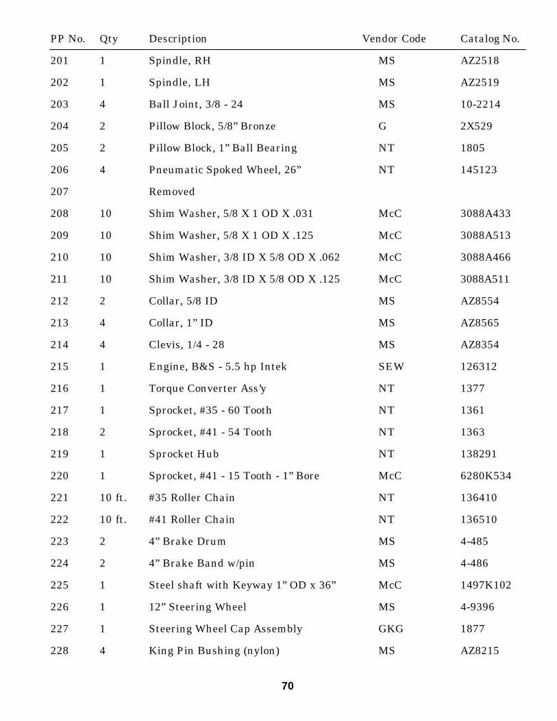
PP No. Qty Description Vendor Code Catalog No.
201 1 Spindle, RH MS AZ2518
202 1 Spindle, LH MS AZ2519
203 4 Ball Joint, 3/8 - 24 MS 10-2214
204 2 Pillow Block, 5/8” Bronze G 2X529
205 2 Pillow Block, 1” Ball Bearing NT 1805
206 4 Pneumatic Spoked Wheel, 26” NT 145123
207 Removed
208 10 Shim Washer, 5/8 X 1 OD X .031 McC 3088A433
209 10 Shim Washer, 5/8 X 1 OD X .125 McC 3088A513
210 10 Shim Washer, 3/8 ID X 5/8 OD X .062 McC 3088A466
211 10 Shim Washer, 3/8 ID X 5/8 OD X .125 McC 3088A511
212 2 Collar, 5/8 ID MS AZ8554
213 4 Collar, 1” ID MS AZ8565
214 4 Clevis, 1/4 - 28 MS AZ8354
215 1 Engine, B&S - 5.5 hp Intek SEW 126312
216 1 Torque Converter Ass’y NT 1377
217 1 Sprocket, #35 - 60 Tooth NT 1361
218 2 Sprocket, #41 - 54 Tooth NT 1363
219 1 Sprocket Hub NT 138291
220 1 Sprocket, #41 - 15 Tooth - 1” Bore McC 6280K534
221 10 ft. #35 Roller Chain NT 136410
222 10 ft. #41 Roller Chain NT 136510
223 2 4” Brake Drum MS 4-485
224 2 4” Brake Band w/pin MS 4-486
225 1 Steel shaft with Keyway 1” OD x 36” McC 1497K102
226 1 12” Steering Wheel MS 4-9396
227 1 Steering Wheel Cap Assembly GKG 1877
228 4 King Pin Bushing (nylon) MS AZ8215
70

229 2 Bronze Bushing - 5/8 ID - 3/4 OD x 1 Lg McC 6391K243
230 2 Connect Link - #41 Chain McC 6261K192
231 2 Connect Link - #35 Chain McC 6261K191
232 1 24” Steering Shaft w/o pitman arms welded MS AZ1868-24
233 1 22” Steering Shaft w/ pitman arms welded MS AZ1867-22
234 1 5/8 x 5/8 Coupling SC 1320-0016
235 5 Control Cable Pulley AS A-124
236 15 ft Control Cable - 3/32 x 7x19 AS 05-04000
237 100 ft Throttle Wire FB 5960245
238 1 Throttle Wire Conduit FB 5960247
239 Pk of 10 Throttle Wire Conduit Clamp FB EGR5979510
240 3 Clevis Pin MS AZ8355
241 3 Cotter Pin MS AZ8419
242 1 Spindle Bracket MS AZ8171
243 2 Bronze Bearing - 1/4 ID - 3/8 OD Flanged McC 6338K413
244 1 Rod End Blank McC 6065K131
245 1 Throttle Pedal MS AZ1806
246 10 Shim Washer, 3/4 ID x 1 1/8 OD x 1/32 McC 3088A434
247 10 Shim Washer, 3/4 ID x 1 1/8 OD x 1/8 McC 3088A514
248 2 Aluminum Disc, 3 1/2 OD x 1/2 thick McC 9035K17
249 7 Tee Nut, 1/4 - 20 x 5/16 High McC 90975A025
250 1 Engine Mounting Plate MS AZ8190
71

Building The1920 Briggs & Stratton
Cycle Car


