Ref.:ADR241B_V2 Issue: 01 15.10.09
Page 1 / 13
ASHIDA ELECTRONICS PVT LTD. ASHIDA HOUSE, Plot No. A-308, Road No. 21, Wagle Industrial Estate,Thane (W)-400 604. INDIA. E-mail: [email protected] Web: www.ashidaelectronics.com
Note: Due to our po l icy to upgrade our products constant ly , we reserve the r ight to supply products which may vary s l ight ly f rom that ind icated above.
Type: ADR241B(ADITYA–V2 Ser ies )
(Pre l iminary)
‚þ¹ªþ¸þ
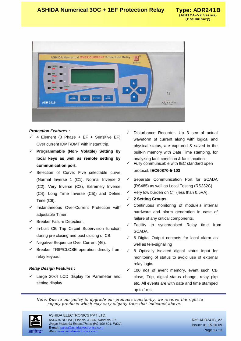
ASHIDA Numerical 3OC + 1EF Protection Relay
PROTH.
PKPFAULT
DTREC
LOCKBF
L5
CLOSETRIP
L6
L7
ADR 241B
ERRPROTH.
PKPFAULT
DTRECDTREC
LOCKBFLOCKBF
L5
CLOSETRIP
L6
L7
ADR 241BADR 241B
ERR
Protection Features :
4 Element (3 Phase + EF + Sensitive EF)
Over current IDMT/DMT with instant trip.
Programmable (Non- Volatile) Setting by
local keys as well as remote setting by
communication port. Selection of Curve: Five selectable curve
(Normal Inverse 1 (C1), Normal Inverse 2
(C2), Very Inverse (C3), Extremely Inverse
(C4), Long Time Inverse (C5)) and Define
Time (C6).
Instantaneous Over-Current Protection with
adjustable Timer.
Breaker Failure Detection.
In-built CB Trip Circuit Supervision function
during pre closing and post closing of CB.
Negative Sequence Over Current (46).
Breaker TRIP/CLOSE operation directly from
relay keypad.
Relay Design Features :
Large 20x4 LCD display for Parameter and setting display.
Disturbance Recorder. Up 3 sec of actual
waveform of current along with logical and physical status, are captured & saved in the built-in memory with Date Time stamping, for analyzing fault condition & fault location.
Fully communicable with IEC standard open
protocol. IEC60870-5-103
Separate Communication Port for SCADA (RS485) as well as Local Testing (RS232C)
Very low burden on CT (less than 0.5VA). 2 Setting Groups. Continuous monitoring of module’s internal
hardware and alarm generation in case of failure of any critical components.
Facility to synchronised Relay time from SCADA.
6 Digital Output contacts for local alarm as well as tele-signalling
8 Optically isolated digital status input for monitoring of status to avoid use of external relay logic.
100 nos of event memory, event such CB close, Trip, digital status change, relay pkp etc. All events are with date and time stamped up to 1ms.

Ref.:ADR241B_V2 Issue: 01 15.10.09
Page 2 / 13
ASHIDA ELECTRONICS PVT LTD. ASHIDA HOUSE, Plot No. A-308, Road No. 21, Wagle Industrial Estate,Thane (W)-400 604. INDIA. E-mail: [email protected] Web: www.ashidaelectronics.com
Note: Due to our po l icy to upgrade our products constant ly , we reserve the r ight to supply products which may vary s l ight ly f rom that ind icated above.
Type: ADR241B(ADITYA–V2 Ser ies )
(Pre l iminary)
‚þ¹ªþ¸þ
ASHIDA Numerical 3OC + 1EF Protection Relay
10 nos of Fault data stored with keypad interface and time stamping.
Description :
ADR241B is second generation of Numerical
Over current IDMT/DMT Relay. It consist all the
necessary protection and monitoring functions
required for Normal feeder, it consist of
1. High Speed Digital DSP Controller
2. Analog Measuring Module
3. Power supply Module
4. Digital Input output module.
The High speed Digital Signal Controller
continuously monitors line phase current and E/F
current. Along with different status input, through
CTs, and optical isolated status connections. The
high-speed micro-controller samples these current
signals through a A/D converter. The Digital
Signal performs powerful Numerical Algorithms
to find out RMS of fundamental & harmonic
contents of the current. All measurement is tuned
to fundamental frequency i.e 50Hz or 60Hz
depending upon setting, thus relay remain stable
during distorted waveform by various industrial
load. All these measure values are then used for
different protection function such as IDMT Over
current protection, Instantaneous Over current
protection, E/F protection etc. These measured
values are also displayed on large 20 x 4 LCD
display for metering purpose. The DSC also
monitors different digital input through optical
isolator and perform some monitoring function
such trip circuit supervision, and control potential
free contact for control CB and generate ALARM
and Tele-signalling.
The power supply module is basically DC – DC
converted designed using modern PWM based
Switching mode technique to convert 110Vdc
station battery supply to the 12V and 24Vdc low
voltage supply for relay electronics and control
circuit. It also provides necessary isolation from
station battery. There are two types of power
supply modules available 1) having range of
77Vdc – 250Vdc. Covering requirement of 110Vdc
and 220Vdc station battery system 2) Wide range
setting 18 Vdc – 250 Vdc.
The relay is having total 8 nos of dual LED of high
intensity for easy identification of type of fault for
easy user interface. LEDs L5, L6 and L7 and
Relay R1 to R6, digital status input and controlled
output are fully programmable via key pad
interface.
Main Functions : The ADR241B are having following protection
functions.
1. 4 stages of Phase Over Current element.
(Ip1>, Ip2>, Ip>> and Ip>>>).
2. 3 stages of 3Io (Internally derived EF) (3Io>,
3Io>> and 3Io>>>).
3. 3 stages of Ie (Externally EF or REF) (Ie>,
Ie>> and Ie>>>).
4. Trip Circuit Supervision.
5. Breaker Failure Detection.
6. Monitoring Functions.
7. Auto Recloser Relay (ARR).
8. Negative Phase Sequence.
9. Relay / Led configuration.

Ref.:ADR241B_V2 Issue: 01 15.10.09
Page 3 / 13
ASHIDA ELECTRONICS PVT LTD. ASHIDA HOUSE, Plot No. A-308, Road No. 21, Wagle Industrial Estate,Thane (W)-400 604. INDIA. E-mail: [email protected] Web: www.ashidaelectronics.com
Note: Due to our po l icy to upgrade our products constant ly , we reserve the r ight to supply products which may vary s l ight ly f rom that ind icated above.
Type: ADR241B(ADITYA–V2 Ser ies )
(Pre l iminary)
‚þ¹ªþ¸þ
ASHIDA Numerical 3OC + 1EF Protection Relay
Each of these functions are independently
programmable and can be enabled or disabled by
user depending upon the requirement.
Over Current Element :
The ADR241B is member of Ashida Numerical
Relay family design for protection general feeder.
The relay has three independent stages of Over
Current (Ip1>, Ip2>, Ip>> & Ip>>>). Stage 1 (>)
Stage 2 (>>) can be programmed as IDMT or
definite time. All major international IDMT curves
are available. Stage 3 (>>>) can be programmed
instantaneous or define time. Range of for stage 1
and 2 is 10% to 250% for Phase. The output of
stage 1 (Ip1>, Ip2>) is separate and not connected
to trip contact. The output of Ip1>, Ip2> can be
assigned to any of 6 programmable relay through
key board. While output of Ip>> and Ip>>> is
connected to trip element. Thus Ip1>, Ip2> can be
used as ALARM before TRIP or can be used to
TRIP another CB before tripping main CB.
Although the curves tend towards infinite when the
current approaches Is (general threshold), the
minimum guaranteed value of the operating
current for all the curves with the inverse time
characteristic is 1.1Is (with a tolerance of ±
0.05Is).
Earth Fault Element :
The Relay has two different type of Earth Fault
one is marked as 3Io and another is marked as Ie.
The 3Io is derived internally by software through
phase current while Ie is measured from external
CT. Thus Ie can be used as Core Balance CT
(CBCT) or Restricted EF (REF) each EF is having
3 stages (>, >>, & >>>). Stage 1 (>) stage 2 (>>)
can be programmed as IDMT or definite time. All
major international IDMT curves are available.
Stage 3 (>>>) can be programmed instantaneous
or define time. Range of stage 1 and stage 2 for
3Io is 10% to 100%, and for stage 3 of 3Io is 50%
to 1200%. The Range for EF is from 5% to 80%
for stage 1 and stage 2 and 50% to 1200% for
stage 3 The output of stage 1 (Ip1>, Ip2>) is
separate and not connected to trip contact. The
output of stage 1 can be assigned to any of 6
programmable relay through key board. While
output of >> and >>> is connected to TRIP
element. Thus I> can be used as ALARM before
TRIP or can be used to TRIP another CB before
Tripping main CB.
Inverse Time Curves :
The each stage thresholds for phase (earth) over
current can be selected with an Inverse Definite
Minimum Time (IDMT) characteristic. The Time
Delay is calculated with a mathematical formula
Curve Type
Description a B
C1 Standard Inverse_1 0.14 0.02 C2 Standard Inverse_2 0.60 0.02 C3 Very Inverse 13.5 1 C4 Extremely inverse 80 2 C5 Long Time Inverse 120 1 C6 Define Time - -
The separate output contact allows to use each
stage for independent function such as stage 1
K * aI
Iref
b1
t =K * aI
Iref
b1
t =K * aI
Iref
I
Iref
b1
t =K * aI
Iref
b1
t =K * aI
Iref
b1
t =K * aI
Iref
I
Iref
b1
t =
Ref.:ADR241B_V2 Issue: 01 15.10.09
Page 4 / 13
ASHIDA ELECTRONICS PVT LTD. ASHIDA HOUSE, Plot No. A-308, Road No. 21, Wagle Industrial Estate,Thane (W)-400 604. INDIA. E-mail: [email protected] Web: www.ashidaelectronics.com
Note: Due to our po l icy to upgrade our products constant ly , we reserve the r ight to supply products which may vary s l ight ly f rom that ind icated above.
Type: ADR241B(ADITYA–V2 Ser ies )
(Pre l iminary)
‚þ¹ªþ¸þ
ASHIDA Numerical 3OC + 1EF Protection Relay
can be used for ALARM stage 2 for tripping or
both can be use for tripping independent CB. Each
stage can enable or disable depend upon
application.
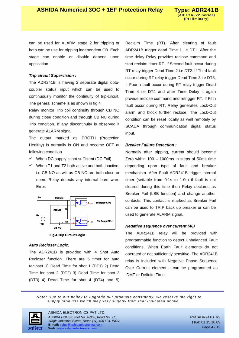
Trip circuit Supervision : The ADR241B is having 2 separate digital opto-
coupler status input which can be used to
continuously monitor the continuity of trip-circuit.
The general scheme is as shown in fig.4
Relay monitor Trip coil continuity through CB NO
during close condition and through CB NC during
Trip condition. If any discontinuity is observed it
generate ALARM signal.
The output marked as PROTH (Protection
Healthy) is normally is ON and become OFF at
following condition
When DC supply is not sufficient (DC Fail)
When T1 and T2 both active and both inactive.
i.e CB NO as will as CB NC are both close or
open. Relay detects any internal hard ware
Error.
Auto Recloser Logic:
The ADR241B is provided with 4 Shot Auto
Recloser function. There are 5 timer for auto
recloser 1) Dead Time for shot 1 (DT1) 2) Dead
Time for shot 2 (DT2) 3) Dead Time for shot 3
(DT3) 4) Dead Time for shot 4 (DT4) and 5)
Reclaim Time (RT). After clearing of fault
ADR241B trigger dead Time 1 i.e DT1. After the
time delay Relay provides reclose command and
start reclaim timer RT. If Second fault occur during
RT relay trigger Dead Time 2 i.e DT2. If Third fault
occur during RT relay trigger Dead Time 3 i.e DT3,
If Fourth fault occur during RT relay trigger Dead
Time 4 i.e DT4 and after Time Delay it again
provide reclose command and retrigger RT. If Fifth
fault occur during RT, Relay generates Lock-Out
alarm and block further reclose. The Lock-Out
condition can be reset locally as well remotely by
SCADA through communication digital status
input.
Breaker Failure Detection :
Normally after tripping, current should become
Zero within 100 – 1000ms in steps of 50ms time
depending upon type of fault and breaker
mechanism. After Fault ADR241B trigger internal
timer (settable from 0.1s to 1.0s) if fault is not
cleared during this time then Relay declares as
Breaker Fail (LBB function) and change another
contacts. This contact is marked as Breaker Fail
can be used to TRIP back up breaker or can be
used to generate ALARM signal.
Negative sequence over current (46)
The ADR241B relay will be provided with
programmable function to detect Unbalanced Fault
conditions. When Earth Fault elements do not
operated or not sufficiently sensitive. The ADR241B
relay is included with Negative Phase Sequence
Over Current element it can be programmed as
IDMT or Definite Time.
1
62
B+
B-
TC
CB NO
CB NC
Fig.4 Trip Circuit Logic
1
62
To Relay CPU
To Relay CPU
TCCOM
T1
T2
1
62
B+
B-
TC
CB NO
CB NC
Fig.4 Trip Circuit Logic
1
62
To Relay CPU
To Relay CPU1
62
B+
B-
TC
CB NO
CB NC
Fig.4 Trip Circuit Logic
1
62
To Relay CPU
To Relay CPU
TCCOM
T1
T2

Ref.:ADR241B_V2 Issue: 01 15.10.09
Page 5 / 13
ASHIDA ELECTRONICS PVT LTD. ASHIDA HOUSE, Plot No. A-308, Road No. 21, Wagle Industrial Estate,Thane (W)-400 604. INDIA. E-mail: [email protected] Web: www.ashidaelectronics.com
Note: Due to our po l icy to upgrade our products constant ly , we reserve the r ight to supply products which may vary s l ight ly f rom that ind icated above.
Type: ADR241B(ADITYA–V2 Ser ies )
(Pre l iminary)
‚þ¹ªþ¸þ
ASHIDA Numerical 3OC + 1EF Protection Relay
Programmable DI/DO and LED:-
The ADR241B Relay is provided with 6 digital
outputs, 8 opto-isolated input and 6 general
purpose LEDs. These can be programmed by local
key board. Any logical of physical status can be
assigned to any relay contact The logic of digital
status input as well as logical status can be formed
and assigned to any of the relay output. The
disturbance record can be trigger from external
logical input.
Setting Group: The ADR241B Relay is provided with two setting
groups i.e. G1 and G2. Any One group is active at
a time. The setting group can be changed from
digital input, this allow user to change relay setting
dynamically as per the outgoing CB load condition.
Monitoring Functions (Event, Disturbance Record):-
Apart from basic protection functions. Relay
continuously monitors all substations operation
through status, it internal functions, internal
hardware etc. if any change is observed it is
marked as event. This events are stored in internal
non-volatile memory along with time stamped.
Following are some of the events recorded, Relay
PKP, Relay Reset, CB Trip, CB Close, Change of
any digital status input, Relay setting changed etc.
Up to 100 such events can be stored and can be
download for detailed analysis. Apart from Event
record Relay also record actual waveform of
current along with all digital and logical status
during fault condition. Up to 10 such waveforms
can be recorded; the duration of disturbance
record is 3 sec. The disturbance record can be
trigger from physical status input as well as
from pick, trip operation of relay. This waveform
can be downloaded through communication port
for further analysis.
Relay Talk Software:
The general communication software is provided
to communicate with relay, known as Relay Talk.
By using this software data such as event log,
disturbance records etc can be down loaded for
further analysis. The disturbance record data can
be saved in standard COMTRADE Format which
is understandable by numbers of relay testing
units for play back.

Ref.:ADR241B_V2 Issue: 01 15.10.09
Page 6 / 13
ASHIDA ELECTRONICS PVT LTD. ASHIDA HOUSE, Plot No. A-308, Road No. 21, Wagle Industrial Estate,Thane (W)-400 604. INDIA. E-mail: [email protected] Web: www.ashidaelectronics.com
Note: Due to our po l icy to upgrade our products constant ly , we reserve the r ight to supply products which may vary s l ight ly f rom that ind icated above.
Type: ADR241B(ADITYA–V2 Ser ies )
(Pre l iminary)
‚þ¹ªþ¸þ
ASHIDA Numerical 3OC + 1EF Protection Relay
Following as some of software clips
All The data can view at time
Event list with real time
Ref.:ADR241B_V2 Issue: 01 15.10.09
Page 7 / 13
ASHIDA ELECTRONICS PVT LTD. ASHIDA HOUSE, Plot No. A-308, Road No. 21, Wagle Industrial Estate,Thane (W)-400 604. INDIA. E-mail: [email protected] Web: www.ashidaelectronics.com
Note: Due to our po l icy to upgrade our products constant ly , we reserve the r ight to supply products which may vary s l ight ly f rom that ind icated above.
Type: ADR241B(ADITYA–V2 Ser ies )
(Pre l iminary)
‚þ¹ªþ¸þ
ASHIDA Numerical 3OC + 1EF Protection Relay
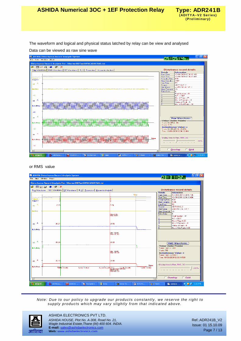
The waveform and logical and physical status latched by relay can be view and analysed
Data can be viewed as raw sine wave
or RMS value

Ref.:ADR241B_V2 Issue: 01 15.10.09
Page 8 / 13
ASHIDA ELECTRONICS PVT LTD. ASHIDA HOUSE, Plot No. A-308, Road No. 21, Wagle Industrial Estate,Thane (W)-400 604. INDIA. E-mail: [email protected] Web: www.ashidaelectronics.com
Note: Due to our po l icy to upgrade our products constant ly , we reserve the r ight to supply products which may vary s l ight ly f rom that ind icated above.
Type: ADR241B(ADITYA–V2 Ser ies )
(Pre l iminary)
‚þ¹ªþ¸þ
ASHIDA Numerical 3OC + 1EF Protection Relay
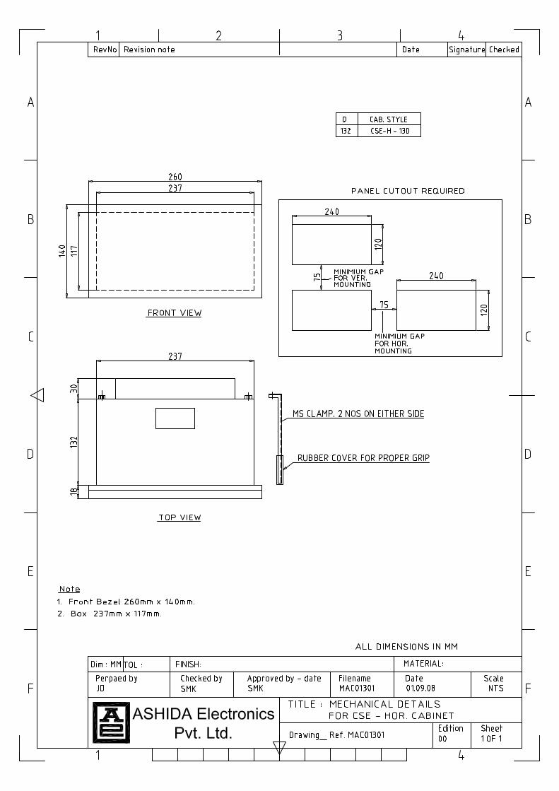
While Order ing Specify the fol lowing Information for ADR241B Relay
Order ing informat ion:
A D R 2 4 1 B - A M - X X X - X X - X - X - X X - X
Example
ADR241B – AM-201-02-3-0-02-0
Type: ADR241B wi th s tandard output Contacts
St . Back termina l layout
Cabinet Type: CSE - H - 130
Aux i l ia ry Supply: 77-250Vdc
CT sec: 1 Amp. / 5 Amp. selectable.
AM XXX XX X
Over current Earth Fault Relay For Adity-V2 series start from 201. For V1 series refer respective document 201 01 Obsolete Version CSE – H - 150 3 201 02 Relay with Standard Back Connections CSE – H - 130 3
D e f i n i t i o n o f M o d e l N o o f A d i t y a S e r i e s o f R e l a y s
A M X X X – X X – X – X – X X – X
Auxiliary Supply
01 = 18 – 52 V dc 04 = 30 V dc 02 = 77 – 250 V dc 05 = 48 V dc 03 = 24 V dc 06 = 18 – 250 Vdc
Reserved for Future Use
PT Secondary 0 = NO PT 1 = 63.5 PT sec
CT Secondary 1 = 1 Amp. 2 = 5 Amp. 3 = 1 Amp. / 5 Amp. Selectable
Ref.:ADR241B_V2 Issue: 01 15.10.09
Page 9 / 13
ASHIDA ELECTRONICS PVT LTD. ASHIDA HOUSE, Plot No. A-308, Road No. 21, Wagle Industrial Estate,Thane (W)-400 604. INDIA. E-mail: [email protected] Web: www.ashidaelectronics.com
Note: Due to our po l icy to upgrade our products constant ly , we reserve the r ight to supply products which may vary s l ight ly f rom that ind icated above.
Type: ADR241B(ADITYA–V2 Ser ies )
(Pre l iminary)
‚þ¹ªþ¸þ
ASHIDA Numerical 3OC + 1EF Protection Relay
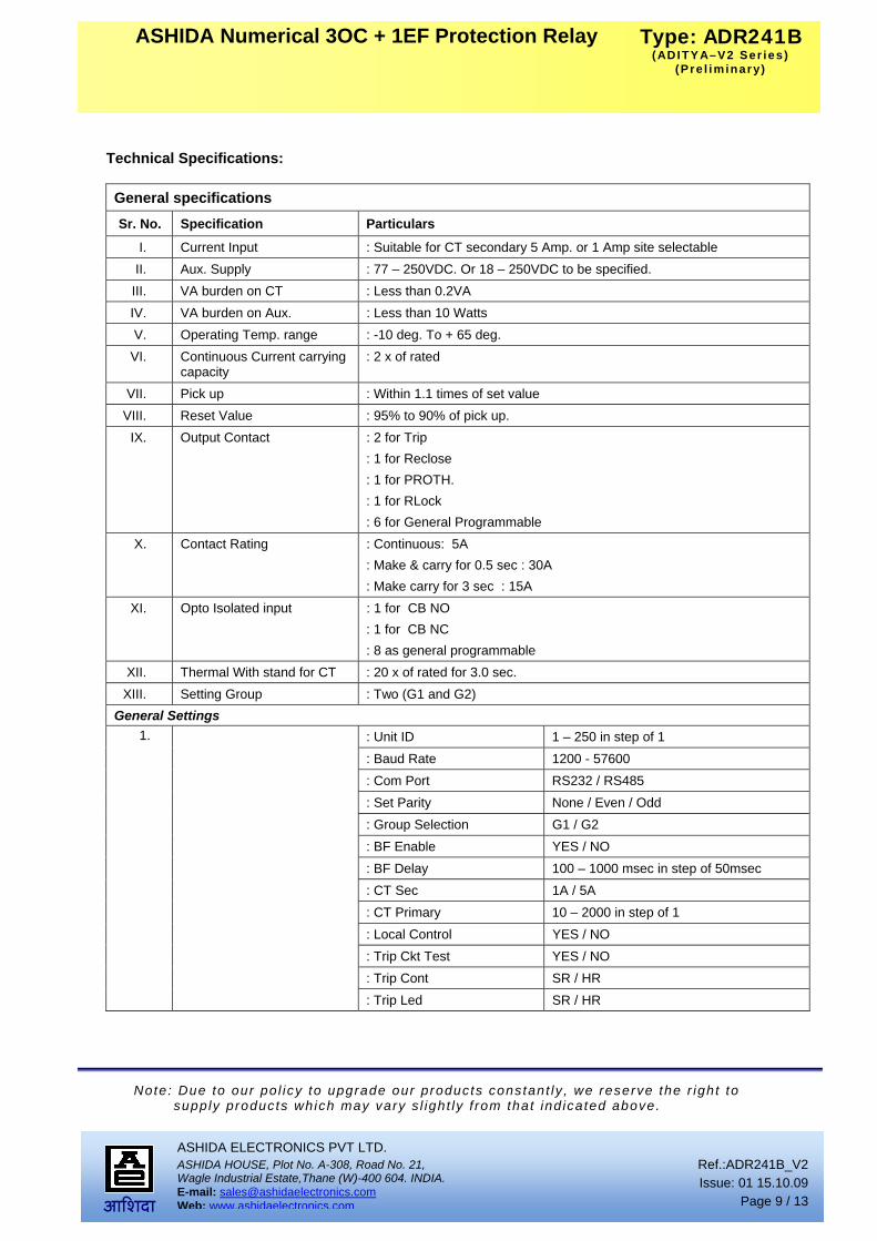
Technical Specifications: General specifications Sr. No. Specification Particulars
I. Current Input : Suitable for CT secondary 5 Amp. or 1 Amp site selectable II. Aux. Supply : 77 – 250VDC. Or 18 – 250VDC to be specified.
III. VA burden on CT : Less than 0.2VA IV. VA burden on Aux. : Less than 10 Watts V. Operating Temp. range : -10 deg. To + 65 deg.
VI. Continuous Current carrying capacity
: 2 x of rated
VII. Pick up : Within 1.1 times of set value VIII. Reset Value : 95% to 90% of pick up.
IX. Output Contact : 2 for Trip : 1 for Reclose : 1 for PROTH. : 1 for RLock : 6 for General Programmable
X. Contact Rating : Continuous: 5A : Make & carry for 0.5 sec : 30A : Make carry for 3 sec : 15A
XI. Opto Isolated input : 1 for CB NO : 1 for CB NC : 8 as general programmable
XII. Thermal With stand for CT : 20 x of rated for 3.0 sec. XIII. Setting Group : Two (G1 and G2)
General Settings : Unit ID 1 – 250 in step of 1 : Baud Rate 1200 - 57600 : Com Port RS232 / RS485 : Set Parity None / Even / Odd : Group Selection G1 / G2 : BF Enable YES / NO : BF Delay 100 – 1000 msec in step of 50msec : CT Sec 1A / 5A : CT Primary 10 – 2000 in step of 1 : Local Control YES / NO : Trip Ckt Test YES / NO : Trip Cont SR / HR
1.
: Trip Led SR / HR

Ref.:ADR241B_V2 Issue: 01 15.10.09
Page 10 / 13
ASHIDA ELECTRONICS PVT LTD. ASHIDA HOUSE, Plot No. A-308, Road No. 21, Wagle Industrial Estate,Thane (W)-400 604. INDIA. E-mail: [email protected] Web: www.ashidaelectronics.com
Note: Due to our po l icy to upgrade our products constant ly , we reserve the r ight to supply products which may vary s l ight ly f rom that ind icated above.
Type: ADR241B(ADITYA–V2 Ser ies )
(Pre l iminary)
‚þ¹ªþ¸þ
ASHIDA Numerical 3OC + 1EF Protection Relay
Phase Section (Ip)
: IP1> Enable YES / NO : IP1> Settings 10% – 250% in steps of 1%. : IP1> Time Multiplier (TMS) x0.02 – x1.00 in steps of 0.01 : IP1> Curve (Operating Time)
C1 – C6 ( IDMT curve C1 – C5 or Define Time C6 )
: IP1> C6 Delay 0 – 1899.9 Sec in steps of 0.1Sec.
: IP2> Enable YES / NO : IP2> Settings 10% – 250% insteps of 1% : IP2> Time Multiplier (TMS) x0.02 – x1.00 in step of 0.01 : IP2> Curve (Operating Time)
C1 – C6 ( IDMT curve C1 – C5 or Define Time C6 )
: IP2> C6 Delay 0 – 1899.9 Sec in steps of 0.1Sec.
: IP>> Enable YES / NO : IP>> Settings 10% – 250% insteps of 1% : IP>> Time Multiplier (TMS) x0.02 – x1.00 in step of 0.01 : IP>> Curve (Operating Time)
C1 – C6 ( IDMT curve C1 – C5 or Define Time C6 )
: IP>> C6 Delay 0 – 99.99 Sec in steps of 0.1Sec. : IP>>> Enable YES / NO : IP>>> Settings 50% – 3000% insteps of 10%
XIV. Phase (OC – G1 )
: IP>>> C6 Delay 0 – 90.00 Sec in steps of 0.01Sec. External Earth Fault Section (Ie)
: IE> Enable YES / NO : IE> Settings 5% – 80% insteps of 1% : IE> Time Multiplier (TMS) x0.02 – x1.00 in step of 0.01. : IE> Curve (Operating Time)
C1 – C6 ( IDMT curve C1 – C5 or Define Time C6 )
: IE> C6 Delay 0 – 99.9 Sec in steps of 0.1Sec.
: IE>> Enable YES / NO : IE>> Settings 5% – 80% insteps of 1% : IE>> Time Multiplier (TMS) x0.02 – x1.00 in step of 0.01. : IE>> Curve (Operating Time)
C1 – C6 ( IDMT curve C1 – C5 or Define Time C6 )
: IE>> C6 Delay 0 – 99.9 Sec in steps of 0.1Sec.
: IE>>> Enable YES / NO : IE>>> Settings 50% – 1200% insteps of 10%
XV. EF – G1
: IE>>> C6 Delay 0 – 3.00 Sec in steps of 0.01Sec.
Ref.:ADR241B_V2 Issue: 01 15.10.09
Page 11 / 13
ASHIDA ELECTRONICS PVT LTD. ASHIDA HOUSE, Plot No. A-308, Road No. 21, Wagle Industrial Estate,Thane (W)-400 604. INDIA. E-mail: [email protected] Web: www.ashidaelectronics.com
Note: Due to our po l icy to upgrade our products constant ly , we reserve the r ight to supply products which may vary s l ight ly f rom that ind icated above.
Type: ADR241B(ADITYA–V2 Ser ies )
(Pre l iminary)
‚þ¹ªþ¸þ
ASHIDA Numerical 3OC + 1EF Protection Relay
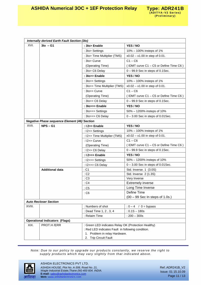
Internally derived Earth Fault Section (3Io)
: 3Io> Enable YES / NO : 3Io> Settings 10% – 100% insteps of 1% : 3Io> Time Multiplier (TMS) x0.02 – x1.00 in step of 0.01. : 3Io> Curve (Operating Time)
C1 – C6 ( IDMT curve C1 – C5 or Define Time C6 )
: 3Io> C6 Delay 0 – 99.9 Sec in steps of 0.1Sec.
: 3Io>> Enable YES / NO : 3Io>> Settings 10% – 100% insteps of 1% : 3Io>> Time Multiplier (TMS) x0.02 – x1.00 in step of 0.01. : 3Io>> Curve (Operating Time)
C1 – C6 ( IDMT curve C1 – C5 or Define Time C6 )
: 3Io>> C6 Delay 0 – 99.9 Sec in steps of 0.1Sec.
: 3Io>>> Enable YES / NO : 3Io>>> Settings 50% – 1200% insteps of 10%
XVI. 3Io – G1
: 3Io>>> C6 Delay 0 – 3.00 Sec in steps of 0.01Sec. Negative Phase sequence Element (46)`Section
: I2>> Enable YES / NO : I2>> Settings 10% – 100% insteps of 1%
: I2>> Time Multiplier (TMS) x0.02 – x1.00 in step of 0.01.
: I2>> Curve (Operating Time)
C1 – C6 ( IDMT curve C1 – C5 or Define Time C6 )
: I2>> C6 Delay 0 – 99.9 Sec in steps of 0.1Sec.
: I2>>> Enable YES / NO : I2>>> Settings 50% – 1200% insteps of 10%
NPS – G1
: I2>>> C6 Delay 0 – 3.00 Sec in steps of 0.01Sec. : C1 Std. Inverse. 1 (3.0S) : C2 Std. Inverse 2 (1.3S) : C3 Very Inverse : C4 Extremely inverse
: C5 Long Time Inverse
XVII.
Additional data
: C6
Define Time (00 – 99 Sec In steps of 1.0s.)
Auto Recloser Section : Numbers of shot : 0 – 4 / 0 = bypass : Dead Time 1, 2 , 3, 4 : 0.1S – 180s
XVIII.
: Relaim Time : 200 – 300s Operational Indicators (Flags)
XIX. PROT.H /ERR : Green LED indicates Relay OK (Protection Healthy) : Red LED indicates Fault in following condition. 1. Problem in relay Hardware. 2. Trip Circuit Fault

Ref.:ADR241B_V2 Issue: 01 15.10.09
Page 12 / 13
ASHIDA ELECTRONICS PVT LTD. ASHIDA HOUSE, Plot No. A-308, Road No. 21, Wagle Industrial Estate,Thane (W)-400 604. INDIA. E-mail: [email protected] Web: www.ashidaelectronics.com
Note: Due to our po l icy to upgrade our products constant ly , we reserve the r ight to supply products which may vary s l ight ly f rom that ind icated above.
Type: ADR241B(ADITYA–V2 Ser ies )
(Pre l iminary)
‚þ¹ªþ¸þ
ASHIDA Numerical 3OC + 1EF Protection Relay
PICK-UP / FAULT : Green LED indicate Start of timer Self Reset (SR) Type
: Red LED indicates FAULT Hand Reset (HR) Type. DT / REC : Green LED indicate Dead Time
: Red LED indicate Reclaim time LOCK / BF : Green LED indicate ARR lock-out (HR) Type
: Red LED indicate Breaker Fail (HR) Type L5 / L6 / L7 : Spare LEDs Programmable
CLOSE / TRIP : Green LED indicate output close relay contact closer (SR) Type : Red LED indicates Output trip relay contact closer (SR) Type
Drawing References : For Back Connections - ADV02402 : For Typical External connection - ADV02303 : For Typical External connection - ADV02304
XX.
: For Cabinet Type - MAC01301
Sr. No. Title Standard no.
Electromagnetic Compatibility Type Test : I. High Frequency test : IEC 60255-22-1, class – III
: Frequency : 1MHz Damped Oscillatory : Longitudinal :5 KV (peak) : Duration: sec duration 2 sec. : Between input current Terminal
II. Electrostatic discharge Direct application
: IEC 60255-22-2 Class III and IEC 61000-4-2 class III. : Contact discharge: 6kV, : Air discharge: 8KV : Polarity: both +ve and –Ve polarities.
III. Indirect application : IEC-61000-4-2, Class-III
IV. Fast transient disturbance : IEC 60255-22-4 and IEC 61000-4-4, class A : 1.2KV; 5/50ns; 5KHz burst duration = 15ms. : Repetition rate 300ms; Both polarities; Ri = 50Ω; duration 1 min.
V. Surge immunity test
: IEC 60255-22-5 / IEC 61000-4-6 class 4 : Differential Mode = 2kV : Common Mode = 4kV : 1.2/50uS , 5 surges of each polarity
VI. Power frequency immunity test : IEC-60255-22-7, Class-A
VII. Power frequency magnetic field test
: IEC-61000-4-8, Class-V
VIII. Radiated electromagnetic field disturbance
: IEC- 60255-22-3 : EN-61000-4-3 : Frequency 80MHz – 1GHz
IX. Conducted Disturbance induced by Radio Frequency field
: IEC 60255-22-6 / IEC 61000-4-6: 1996. : Freq. 150kHz – 80MHz, Amplitude 10 V, Modulation 80% AM @ 1 KHz

Ref.:ADR241B_V2 Issue: 01 15.10.09
Page 13 / 13
ASHIDA ELECTRONICS PVT LTD. ASHIDA HOUSE, Plot No. A-308, Road No. 21, Wagle Industrial Estate,Thane (W)-400 604. INDIA. E-mail: [email protected] Web: www.ashidaelectronics.com
Note: Due to our po l icy to upgrade our products constant ly , we reserve the r ight to supply products which may vary s l ight ly f rom that ind icated above.
Type: ADR241B(ADITYA–V2 Ser ies )
(Pre l iminary)
‚þ¹ªþ¸þ
ASHIDA Numerical 3OC + 1EF Protection Relay
X. AC Ripple in DC supply
Test : IEC 60255-11
XI. Radiated emission : IEC- 60255-25 Insulation tests:
XII. High Voltage Test
: IEC 60255-5. class – III : At 2.5kV 50Hz between all terminal connected together and earth for 1
minutes XIII. Impulse Voltage Test
: IEC60255-5. class – III : Test voltage: 5KV (peak) 1.2 / 50us, : Energy :0.5 J, : Polarity : + ve and – Ve : Nos. of impulses : 3 positive and 3 negative impulse : Duration between Impulses : 5 sec.
Environmental tests: XIV. Cold test Storage test : IEC-60068-2-1
XV. Dry heat test : IEC-60068-2-2
XVI. Damp heat test, steady state : IEC-60068-2-3
XVII. Damp heat test, cyclic : IEC-60068-2-30
CE compliance
XVIII. Immunity : IEC-60255-26
XIX. Emissive Test : IEC- 60255-26
XX. Low voltage directive : EN-50178
Mechanical tests
XXI. Vibration : IEC 60255-21-1 class 1 : Frequency Range = 10Hz – 150Hz , acceleration. = 1gn (9.8 m/s2) : Sweep rate 1 octave/min; 20 cycle in 3 orthogonal axis.
XXII. Shock and bump : IEC- 60255-21-2
XXIII. Seismic : IEC-60255-21-3
Revision Date Description 01 15.10. 2009 Original Specification