Cat. No.
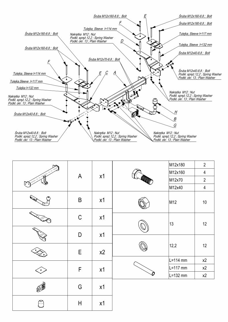
2000Kg 85Kg
OPEL VECTRA C com. 2002 -
O/027
10,72kN
e20*94/20*1333*00

���
����
0Km 1000Km
Moment skręcający dla śrub i nakrętek (8.8) Torgue settings for nuts and bolts (8.8)
M8
M10
M12
M14
M16
25Nm
55Nm
85Nm
135Nm
195Nm
x1
x1
x1
x1
x2
x1
x1
x1
M12x180 2M12x160 4M12x70 2M12x40 4
M12 10
13 12
12,2 12
L=114 mm x2L=117 mm x2L=132 mm x2
B
Tulej
ka, S
leeve
l=11
4 mm
Tulej
ka, S
leeve
l=11
4 mm
Tulej
ka, S
leeve
l=11
7 mm
Tulej
ka, S
leeve
l=13
2 mm
Tulej
ka l=
132 m
m
Tulej
ka,S
leeve
l=11
7 mm
Śrub
a M12
x180
-8.8
; Bolt
Śrub
a M12
x180
-8.8
; Bolt
Śrub
a M12
x160
-8.8
; Bolt
Śrub
a M12
x160
-8.8
; Bolt
Pkt.1
Pkt.1
Śrub
a M12
x70-
8.8 ;
Bolt
Pkt.2
Pkt.2
Pkt.2
Nakrę
tka M
10 ; N
utPo
dkł. s
pręż
.10,2
; Spr
ing W
ashe
rPo
dkł. o
kr. 10
,5 ; P
lain W
ashe
r
Śrub
a M12
x160
-8.8
; Bolt
Śrub
a M12
x40-
8.8 ;
Bolt
Podk
ł. spr
ęż.12
,2 ; S
pring
Was
her
Podk
ł. okr.
13 ; P
lain W
ashe
r
Nakrę
tka M
10 ; N
utPo
dkł. s
pręż
.10,2
; Spr
ing W
ashe
rPo
dkł. o
kr. 10
,5 ; P
lain W
ashe
r
Nakrę
tka M
12 ; N
utPo
dkł. s
pręż
.12,2
; Spr
ing W
ashe
rPo
dkł. o
kr. 13
; Plai
n Was
her
Śrub
a M12
x40-
8.8 ;
Bolt
Śrub
a M12
x40-
8.8 ;
Bolt
Śrub
a M12
x40-
8.8 ;
Bolt
Podk
ł. spr
ęż.12
,2 ; S
pring
Was
her
Podk
ł. okr.
13 ; P
lain W
ashe
r
Nakrę
tka M
10 ; N
utPo
dkł. s
pręż
.10,2
; Spr
ing W
ashe
rPo
dkł. o
kr. 10
,5 ; P
lain W
ashe
rNa
krętka
M10
; Nut
Podk
ł. spr
ęż.10
,2 ; S
pring
Was
her
Podk
ł. okr.
10,5
; Plai
n Was
her
Nr ka
talog
owy
Marka
96-1
11 K
owie
sy, C
hojn
ata
23 A
tel.
+48
46
831
73 3
1

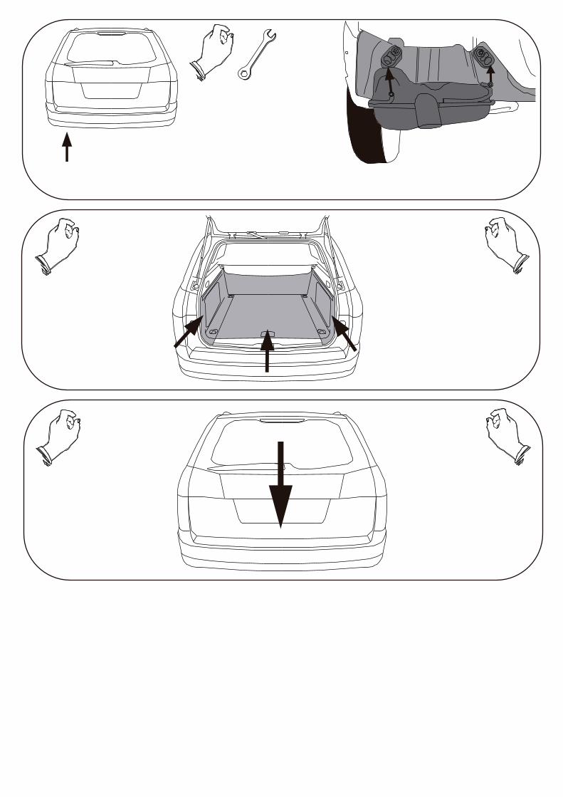
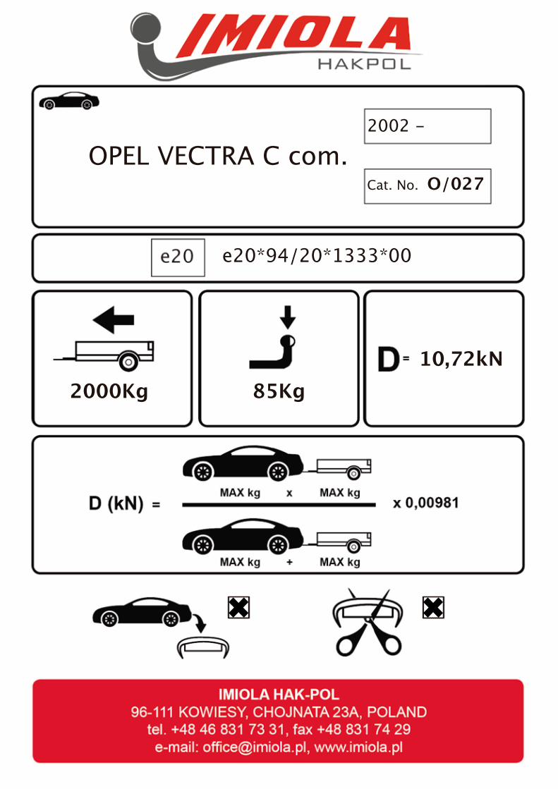
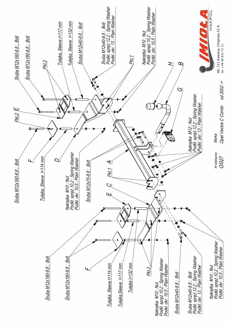
• Zdjąć tłumik z wieszaków, odkręcić osłonę termiczną.• W bagażniku odkręcić osłonę tylnego pasa i odnaleźć pod wykładziną na płycie bagażnika technologiczne punkty mocowania zaczepu (muszą się zgadzać z otworami we wspornikach zaczepu). W punktach tych wykonać otwory ø 22 (pkt 2).• W otwory w bagażniku, w lewą podłużnicę włożyć śruby M12x180 8.8 (1 szt) oraz M12x160 (2 szt) razem z tulejami stosując nakładki G i E (pkt 2).• Od spodu podłuznic przykręcić luźno element C.• W otwory w bagażniku, w prawą podłużnicę włożyć śruby M10x180 8.8 (1 szt) oraz M12x160 (2 szt) razem z tulejami stosując nakładki G i F (pkt 2).• Od spodu podłużnic przykręcić luźno element D.• Do elementów C i D przykręcić luźno belkę zaczepu A śrubami M12x40 8.8 (pkt 1).• Podłączyć instalację elektryczną, przykręcić kulę zaczepu i blachę gniazda elektrycznego (pkt 3) (należy zastosować specjalną wiązkę elektryczną z modułem).• Dokręcić wszystkie śruby z momentem wg tabeli.• Przykręcić osłonę termiczną, zamontować tłumik.
• Remove the damper from the hangers, unscrew the thermal shield.• Unscrew the shield of the rear belt in the boot and �nd the tow bar �tting points under covering, on the plate of the boot (these points have to agree with the holes in the supporters of the tow bar). Drill the holes ø 22 in these points (point 2).• Insert the bolts M12x180 8.8 (1 piece), M12x160 8.8 (2 pieces) and sleeves in the holes in boot, in the left metal clamp using plates G and E (point 2).• Screw slightly the element C of the bottom of the metal clamps.• Insert the bolts M10x180 8.8 (1 piece), M12x160 8.8 (2 pieces) and sleeves in the holes in boot, in the right metal clamp using plates G and F (point 2).• Screw slightly the elements D of the bottom of the metal clamps.• Screw slightly the main bar A to the elements C and D with bolts M12x40 8.8 (point 1).• Connect the electric wires, �x the ball and electric plate (point 3) (is necessary to use the electronic module).• Tighten all the bolts according to the torque setting- see the table.• Screw the thermal shield and assemble the damper.

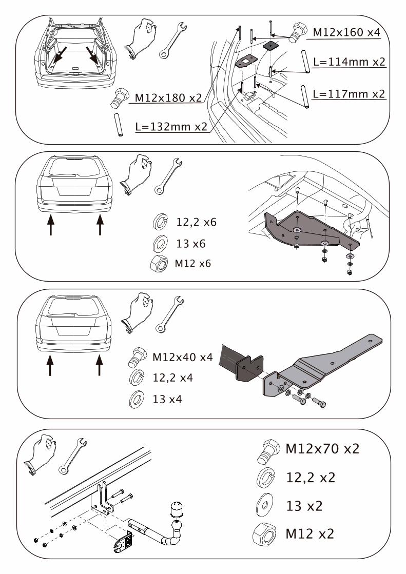
M12x70 x2
12,2 x2
13 x2
M12 x2
M12x160 x4
M12x180 x2
L=114mm x2
L=117mm x2
L=132mm x2
12,2 x6
13 x6M12 x6
12,2 x4
13 x4
M12x40 x4