© 2008 ANSYS, Inc. All rights reserved. 1 ANSYS, Inc. Proprietary
2008 International 2008 International ANSYS ConferenceANSYS Conference
Multi-Objective Optimization of BGA Packages
Marco Spagnolo1,2
Alberto Bassanese1
Can Ozcan1
1: Ozen Engineering 2: EnginSoft

© 2008 ANSYS, Inc. All rights reserved. 2 ANSYS, Inc. Proprietary
SummaryIn this presentation we will describe an optimisation procedure that can be conveniently and efficiently employed for determining :
- the design parameters that are critical for BGA packages;- their relative importance;- the actual BGA optimal design;
Both geometric parameters and material properties will be considered.2D and 3D approaches will be compared.Contents - The Software - FE models - Boundary Conditions - Loads - Workflow Set-up and Post-processing - Results - Conclusions

© 2008 ANSYS, Inc. All rights reserved. 3 ANSYS, Inc. Proprietary
Finite Element Models
The subsequent approach was followed for:
- 2D model (APDL parametric model) without Underfill - 2D model (Workbench parametric model) without Underfill - 3D model* (APDL parametric model) without Underfill - 3D model* (APDL parametric model) with Underfill
Input VariablesGeometric ParametersMaterial properties
* only 3D model results are presented in this presentation.
© 2008 ANSYS, Inc. All rights reserved. 4 ANSYS, Inc. Proprietary
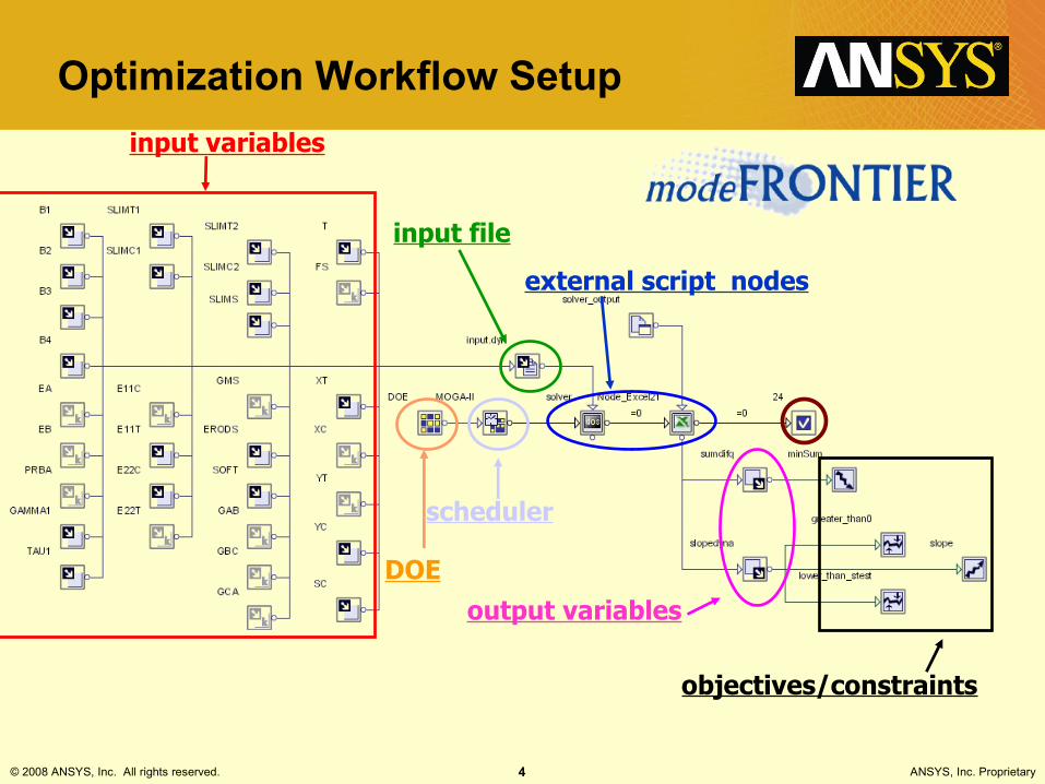
Optimization Workflow Setupinput variables
input file
DOE
scheduler
external script nodes
output variables
objectives/constraints
© 2008 ANSYS, Inc. All rights reserved. 5 ANSYS, Inc. Proprietary
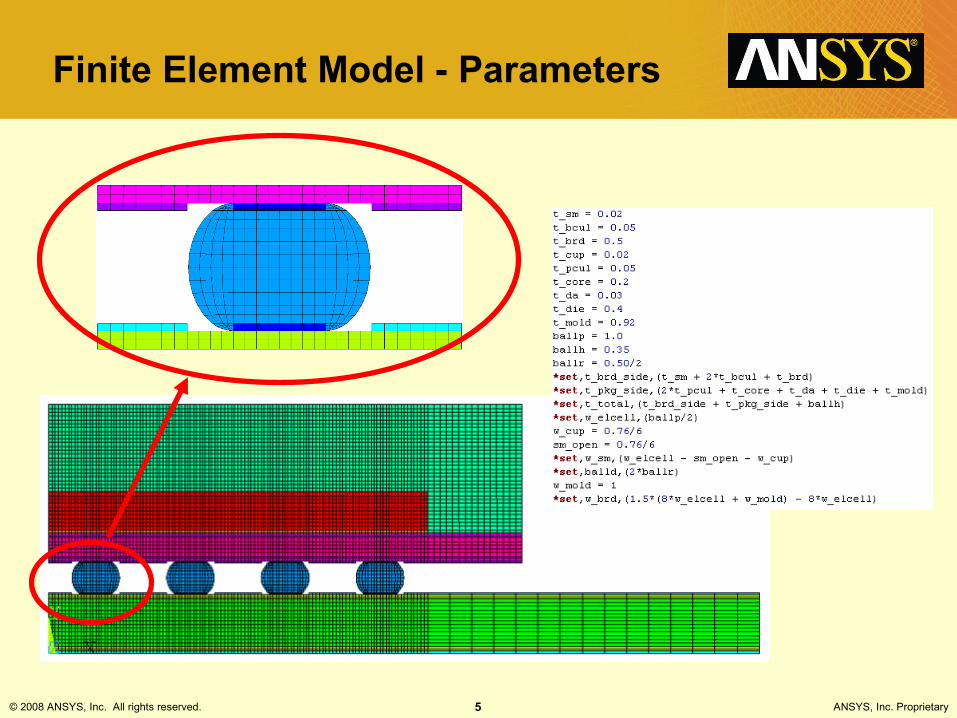
Finite Element Model - Parameters
© 2008 ANSYS, Inc. All rights reserved. 6 ANSYS, Inc. Proprietary
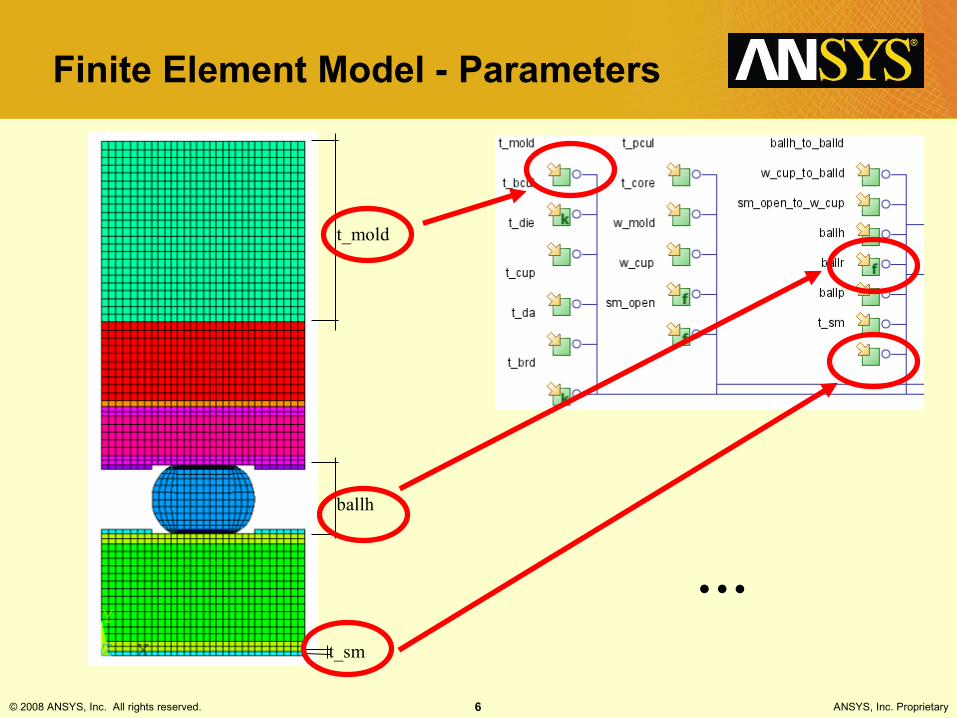
Finite Element Model - Parameters
t_mold
t_sm
ballh
…
© 2008 ANSYS, Inc. All rights reserved. 7 ANSYS, Inc. Proprietary
Finite Element Model – Element Types
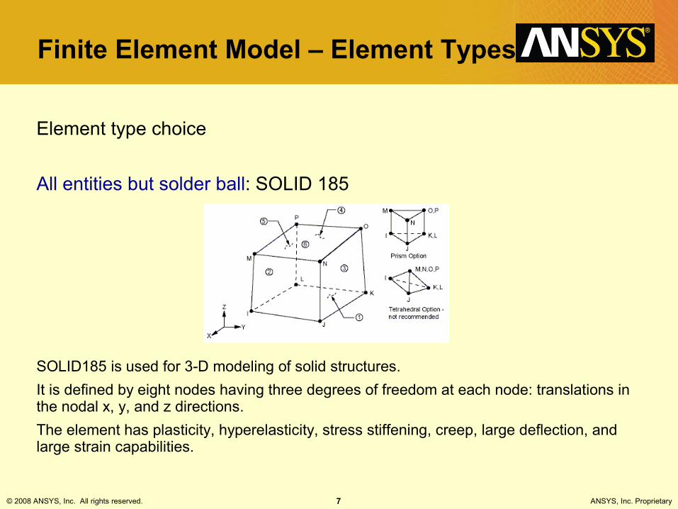
Element type choice
All entities but solder ball: SOLID 185
SOLID185 is used for 3-D modeling of solid structures.It is defined by eight nodes having three degrees of freedom at each node: translations in the nodal x, y, and z directions.The element has plasticity, hyperelasticity, stress stiffening, creep, large deflection, and large strain capabilities.

© 2008 ANSYS, Inc. All rights reserved. 8 ANSYS, Inc. Proprietary
Finite Element Model – Element Types
Element type choice
Solder ball: VISCO 107
VISCO107 is used for 3-D modeling of solid structures.It is defined by eight nodes having three degrees of freedom at each node: translations in the nodal x, y and z directions.The element is designed to solve both isochoric (volume preserving) rate-independent and rate-dependent large strain plasticity problems. Iterative solution procedures must be used with VISCO107 since it is used to represent highly nonlinear behavior. Large deflections must be active in order to update the geometry in each substep
© 2008 ANSYS, Inc. All rights reserved. 9 ANSYS, Inc. Proprietary
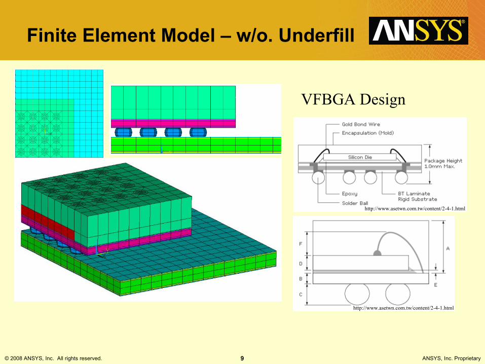
Finite Element Model – w/o. Underfill
VFBGA Design
http://www.asetwn.com.tw/content/2-4-1.html
http://www.asetwn.com.tw/content/2-4-1.html
© 2008 ANSYS, Inc. All rights reserved. 10 ANSYS, Inc. Proprietary
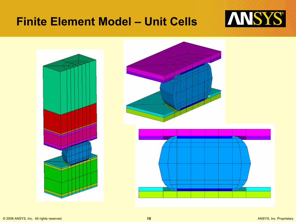
Finite Element Model – Unit Cells
© 2008 ANSYS, Inc. All rights reserved. 11 ANSYS, Inc. Proprietary
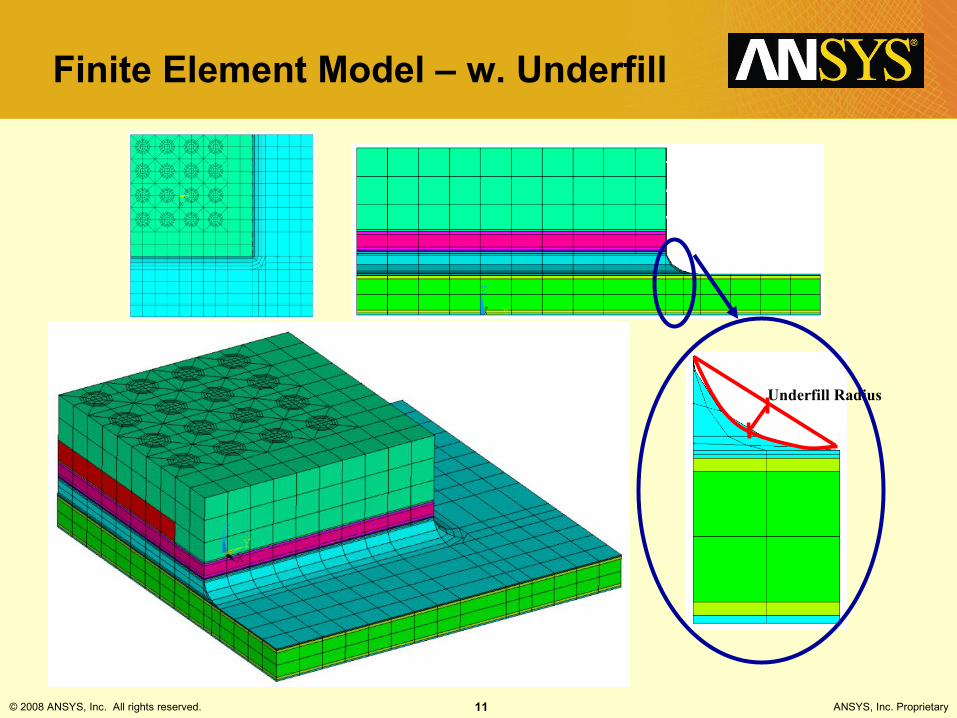
Finite Element Model – w. Underfill
Underfill Radius

© 2008 ANSYS, Inc. All rights reserved. 12 ANSYS, Inc. Proprietary
Finite Element Model – Unit Cells
© 2008 ANSYS, Inc. All rights reserved. 13 ANSYS, Inc. Proprietary
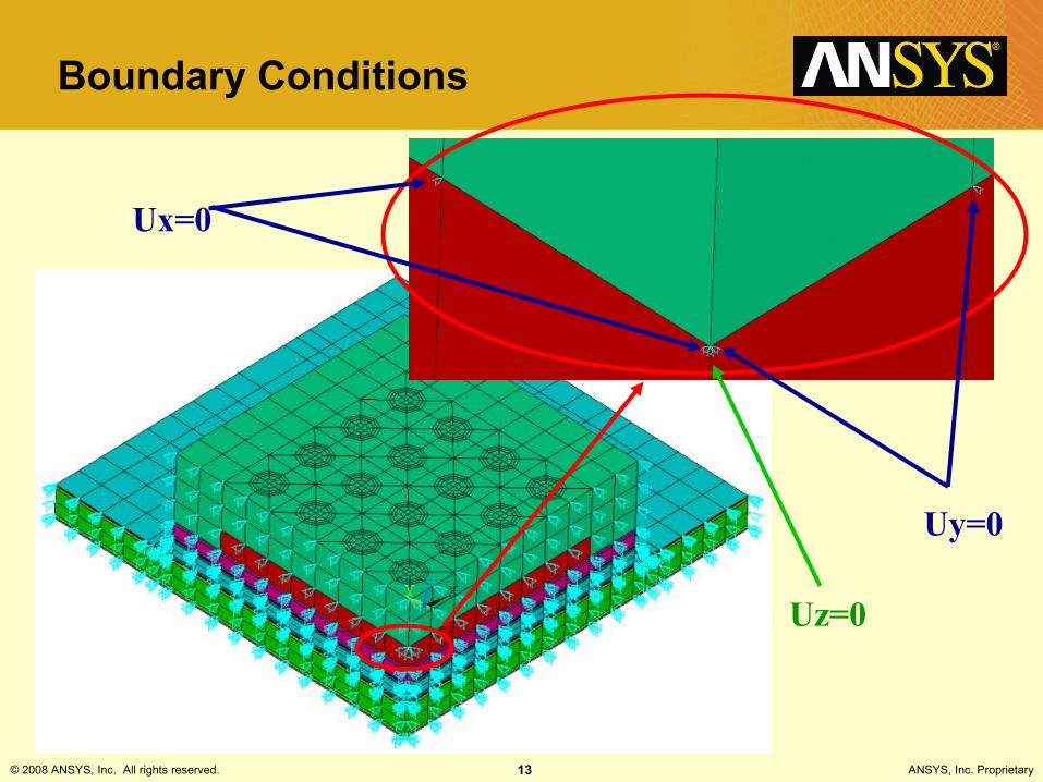
Boundary Conditions
Uz=0
Ux=0
Uy=0
© 2008 ANSYS, Inc. All rights reserved. 14 ANSYS, Inc. Proprietary
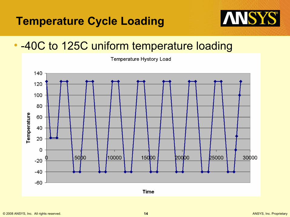
Temperature Cycle Loading
• -40C to 125C uniform temperature loading
© 2008 ANSYS, Inc. All rights reserved. 15 ANSYS, Inc. Proprietary
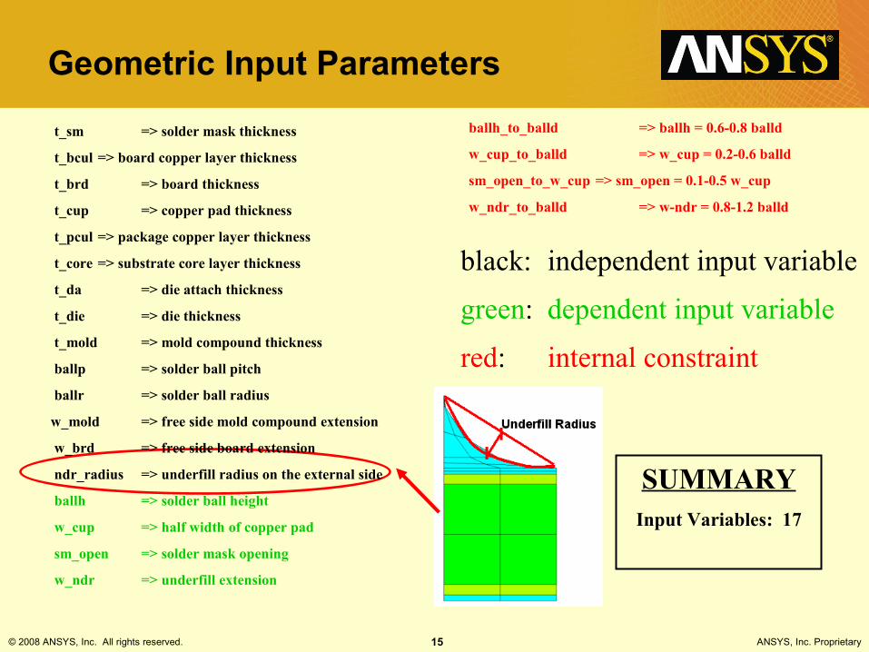
Geometric Input Parameters
t_sm => solder mask thickness
t_bcul => board copper layer thickness
t_brd => board thickness
t_cup => copper pad thickness
t_pcul => package copper layer thickness
t_core => substrate core layer thickness
t_da => die attach thickness
t_die => die thickness
t_mold => mold compound thickness
ballp => solder ball pitch
ballr => solder ball radius
w_mold => free side mold compound extension
w_brd => free side board extension
ndr_radius => underfill radius on the external side
ballh => solder ball height
w_cup => half width of copper pad
sm_open => solder mask opening
w_ndr => underfill extension
ballh_to_balld => ballh = 0.6-0.8 balld
w_cup_to_balld => w_cup = 0.2-0.6 balld
sm_open_to_w_cup => sm_open = 0.1-0.5 w_cup
w_ndr_to_balld => w-ndr = 0.8-1.2 balld
black: independent input variable
green: dependent input variable
red: internal constraint
SUMMARYInput Variables: 17

© 2008 ANSYS, Inc. All rights reserved. 16 ANSYS, Inc. Proprietary
Material Input Variables
SUMMARY – 3D MODELS
With UF Whithout UF
Number of Considered Geometric Parameters: 17 16
Number of Considered Material Properties: 20 18
Total: 37 34
Material Prop. ID Factorsbrd_E Materials_Properties[0]brd_sm_CTE Materials_Properties[1]pkg_sm_E Materials_Properties[2]pkg_sm_CTE Materials_Properties[3]die_E Materials_Properties[4]die_CTE Materials_Properties[5]ball_E Materials_Properties[6]ball_CTE Materials_Properties[7]pkg_core_E Materials_Properties[8]pkg_core_CTE Materials_Properties[9]
Material Prop. ID Factorsbrd_core_E Materials_Properties[10]brd_core_CTE Materials_Properties[11]dieat_E Materials_Properties[12]dieat_CTE Materials_Properties[13]pkg_cu_E Materials_Properties[14]pkg_cu_CTE Materials_Properties[15]mold_E Materials_Properties[16]mold_CTE Materials_Properties[17]ndr_fill_E Materials_Properties[18]ndr_fill_CTE Materials_Properties[19]
CTE = Coefficient Of thermal Expansion E = Young’s Modulus

© 2008 ANSYS, Inc. All rights reserved. 17 ANSYS, Inc. Proprietary
Input Parameters – Range Setup
© 2008 ANSYS, Inc. All rights reserved. 18 ANSYS, Inc. Proprietary
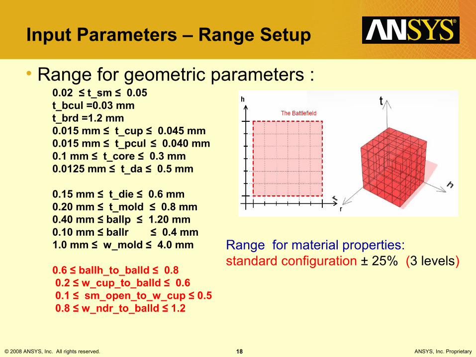
Input Parameters – Range Setup
• Range for geometric parameters :
Range for material properties: standard configuration ± 25% (3 levels)
0.02 ≤ t_sm ≤ 0.05 t_bcul =0.03 mmt_brd =1.2 mm0.015 mm ≤ t_cup ≤ 0.045 mm0.015 mm ≤ t_pcul ≤ 0.040 mm0.1 mm ≤ t_core ≤ 0.3 mm 0.0125 mm ≤ t_da ≤ 0.5 mm
0.15 mm ≤ t_die ≤ 0.6 mm0.20 mm ≤ t_mold ≤ 0.8 mm0.40 mm ≤ ballp ≤ 1.20 mm0.10 mm ≤ ballr ≤ 0.4 mm1.0 mm ≤ w_mold ≤ 4.0 mm
0.6 ≤ ballh_to_balld ≤ 0.8 0.2 ≤ w_cup_to_balld ≤ 0.6 0.1 ≤ sm_open_to_w_cup ≤ 0.5 0.8 ≤ w_ndr_to_balld ≤ 1.2
© 2008 ANSYS, Inc. All rights reserved. 19 ANSYS, Inc. Proprietary
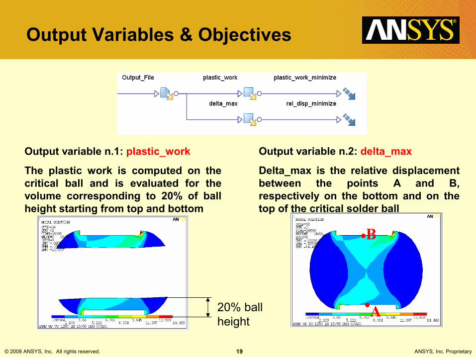
Output Variables & Objectives
Output variable n.1: plastic_work
The plastic work is computed on the critical ball and is evaluated for the volume corresponding to 20% of ball height starting from top and bottom
Output variable n.2: delta_max
Delta_max is the relative displacement between the points A and B, respectively on the bottom and on the top of the critical solder ball
B
A20% ball height

© 2008 ANSYS, Inc. All rights reserved. 20 ANSYS, Inc. Proprietary
Work flow for Optimization Setup
• First level text – Arial 28 pt.– Second level text – Arial 28 pt.
• Third level text – Arial 24 pt.– Fourth level text – Arial 22 pt.
• Fifth level text – Arial 20 pt.
© 2008 ANSYS, Inc. All rights reserved. 21 ANSYS, Inc. Proprietary
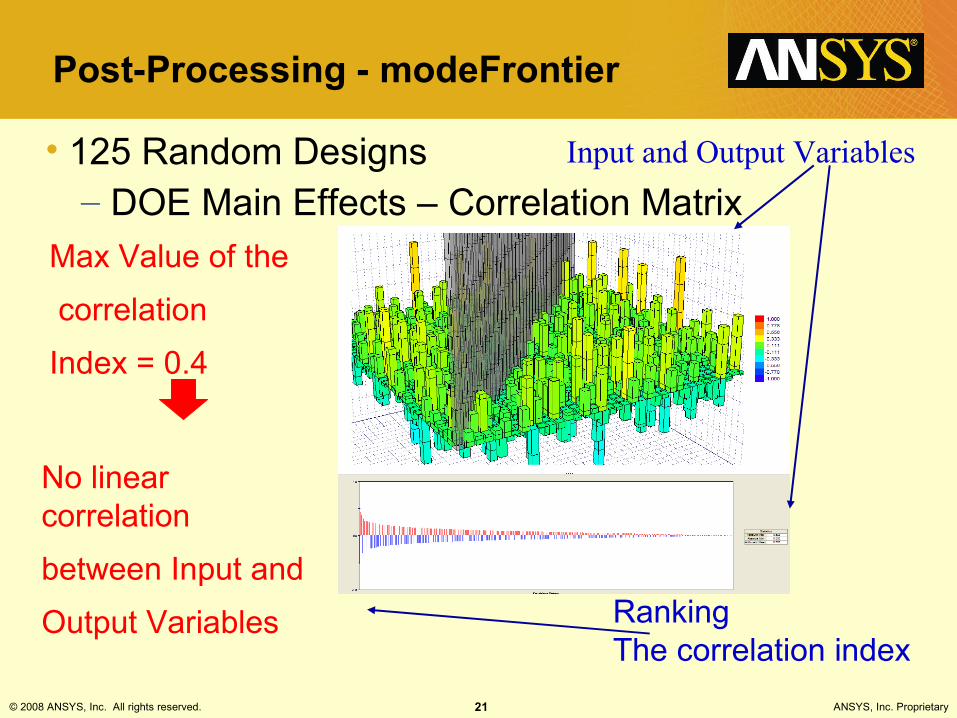
Post-Processing - modeFrontier
Max Value of the
correlation
Index = 0.4
No linear correlation
between Input and
Output Variables RankingThe correlation index
Input and Output Variables• 125 Random Designs– DOE Main Effects – Correlation Matrix
© 2008 ANSYS, Inc. All rights reserved. 22 ANSYS, Inc. Proprietary
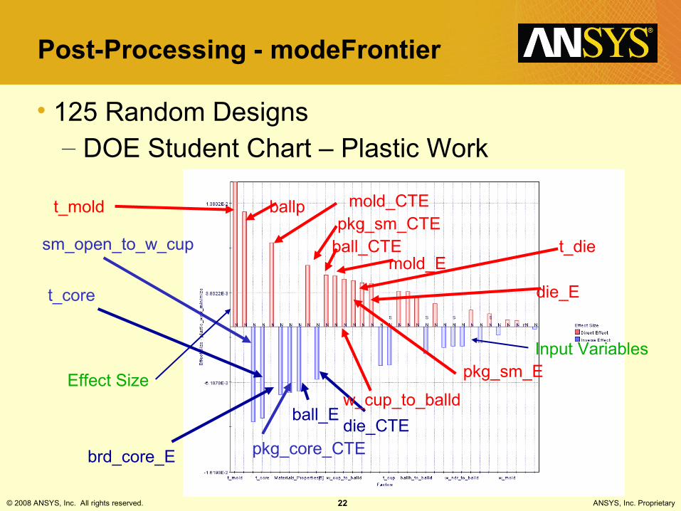
Post-Processing - modeFrontier
• 125 Random Designs– DOE Student Chart – Plastic Work
sm_open_to_w_cup
t_core
brd_core_E pkg_core_CTE
ball_Edie_CTE
t_mold ballp mold_CTEpkg_sm_CTE
ball_CTEmold_E
w_cup_to_balld
pkg_sm_E
t_die
die_E
Input Variables
Effect Size

© 2008 ANSYS, Inc. All rights reserved. 23 ANSYS, Inc. Proprietary
Post-Processing - modeFrontier
• 125 Random Designs– DOE Student Chart – Both Outputs
t_mold (1, -0.9)
ballp (0.7, 0.4)
mold_CTE (0.58, -1.0)
sm_open_to_w_cup
(-0.65, -0.07)
t_core
(-0.63, 0.4)
Input Variables
Plastic WorkRel. Displacement

© 2008 ANSYS, Inc. All rights reserved. 24 ANSYS, Inc. Proprietary
Post-Processing - modeFrontier
• 125 Random Designs– DOE Student Chart – Overall
Full Name Factor Plastic Workbrd_sm_CTE Materials_Properties[1] -0.015 [0.476]
pkg_cu_CTE Materials_Properties[15] 0.021 [0.466]
dieat_CTE Materials_Properties[13] 0.044 [0.437]
w_mold 0.048 [0.427]
dieat_E Materials_Properties[12] 0.092 [0.365]
Full Name Factor Rel. Displ. t_da 0.028 [0.441]
t_sm -0.053 [0.399]
brd_core_E Materials_Properties[10] 0.067 [0.379]
sm_open_to_w_cup -0.068 [0.394]
ball_CTE Materials_Properties[7] -0.069 [0.359]
Full Name Factor Rel. Displ. Plastic Workdieat_CTE Materials_Properties[13] -0.146 [0.246] 0.044 [0.437]
w_mold -0.107 [0.298] 0.048 [0.427]
t_da 0.028 [0.441] 0.117 [0.320]
brd_E Materials_Properties[0] -0.127 [0.275] -0.132 [0.316]
t_pcul 0.151 [0.217] -0.184 [0.231]
Displacement Plastic Work

© 2008 ANSYS, Inc. All rights reserved. 25 ANSYS, Inc. Proprietary
Post-Processing - modeFrontier
• 125 Random Designs– Initial DOE Population
Scatter Chart : The Design Space
plastic work
rela
tive
disp
lace
men
t

© 2008 ANSYS, Inc. All rights reserved. 26 ANSYS, Inc. Proprietary
Post-Processing - modeFrontier
• Virtual Optimization with 3000 virtual designs
After running MOGAII within modeFROINTER
rela
tive
disp
lace
men
t
plastic work
Scatter Chart : The Design Space
© 2008 ANSYS, Inc. All rights reserved. 27 ANSYS, Inc. Proprietary
Post-Processing - modeFrontier
• Response Surface (RS) Modeling – RSs are a collection of mathematical and statistical techniques
useful for the modeling of problems – RSM can be trained from an available database of designs
(coming from a DOE, an optimization or from experimental data)– Once trained, they can be used to extrapolate the outputs of the
system: a virtual optimization can be run, in which all (or a part) of the design are extrapolated from RSM, saving a lot of CPU time
– Predictions made within the observed space of variable values are called interpolations.
– Predictions outside the observed space are called extrapolations and require caution
© 2008 ANSYS, Inc. All rights reserved. 28 ANSYS, Inc. Proprietary
Post-Processing - modeFrontier
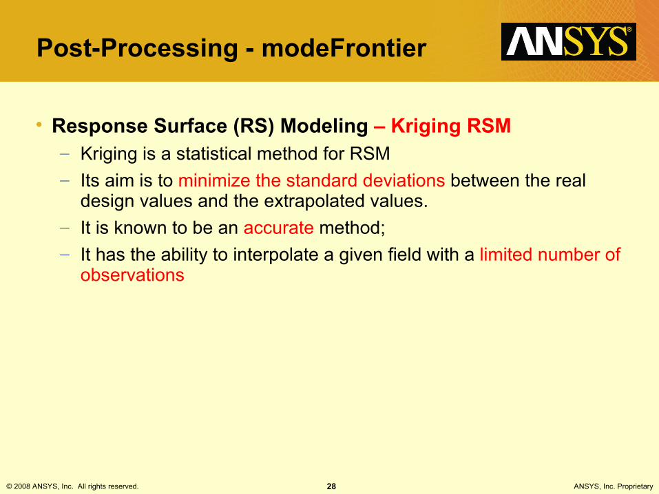
• Response Surface (RS) Modeling – Kriging RSM– Kriging is a statistical method for RSM– Its aim is to minimize the standard deviations between the real
design values and the extrapolated values.– It is known to be an accurate method;– It has the ability to interpolate a given field with a limited number of
observations
© 2008 ANSYS, Inc. All rights reserved. 29 ANSYS, Inc. Proprietary
Post-Processing - modeFrontier
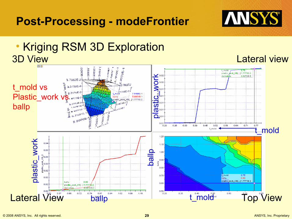
• Kriging RSM 3D ExplorationLateral view
Top View
3D View
Lateral View
t_mold vs Plastic_work vs ballp
ballp
t_mold
t_mold
ballp
plas
tic_w
ork
plas
tic_w
ork

© 2008 ANSYS, Inc. All rights reserved. 30 ANSYS, Inc. Proprietary
Post-Processing - modeFrontier
• Kriging RSM 3D Exploration
30
t_mold vs plastic_work vs ballp
3D View
t_mold
Plastic _work
ballp

© 2008 ANSYS, Inc. All rights reserved. 31 ANSYS, Inc. Proprietary
Post-Processing - modeFrontier
• Virtual Optimization– Scatter Chart : The Design Space
After running MOGAII within modeFROINTER
plastic work
rela
tive
disp
lace
men
t
PARETO FRONTIEROPTIMUM DESIGN

© 2008 ANSYS, Inc. All rights reserved. 32 ANSYS, Inc. Proprietary
Validation of Virtual Optimization
• Geometric configuration for the real optimal design
© 2008 ANSYS, Inc. All rights reserved. 33 ANSYS, Inc. Proprietary
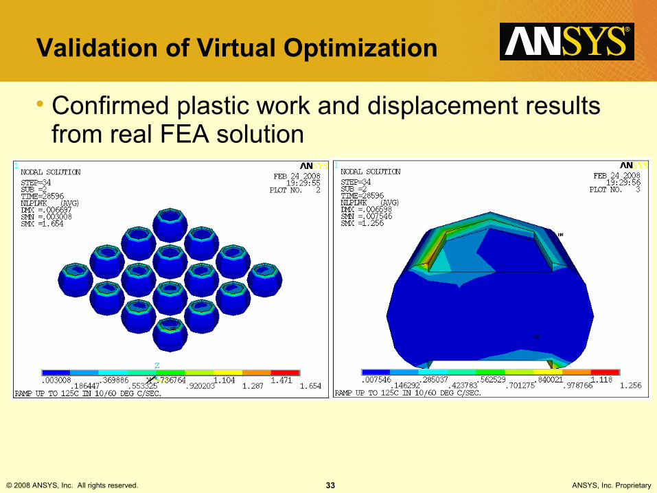
Validation of Virtual Optimization
• Confirmed plastic work and displacement results from real FEA solution
© 2008 ANSYS, Inc. All rights reserved. 34 ANSYS, Inc. Proprietary
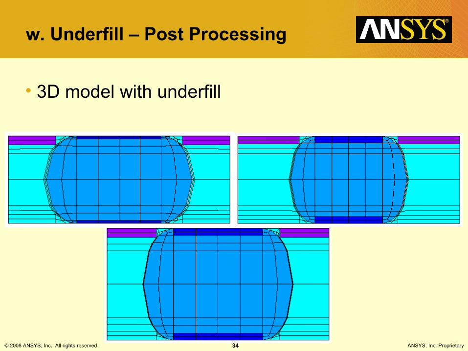
w. Underfill – Post Processing
• 3D model with underfill

© 2008 ANSYS, Inc. All rights reserved. 35 ANSYS, Inc. Proprietary
w. Underfill – Post Processing
•
Rel. Displacement Minimization
sm_open_to_w_cup
T_mold
Mold CTE
W_cup_to_balld
Ball pitch
Ball radius
Underfill CTE
Plastic Work Minimization
© 2008 ANSYS, Inc. All rights reserved. 36 ANSYS, Inc. Proprietary
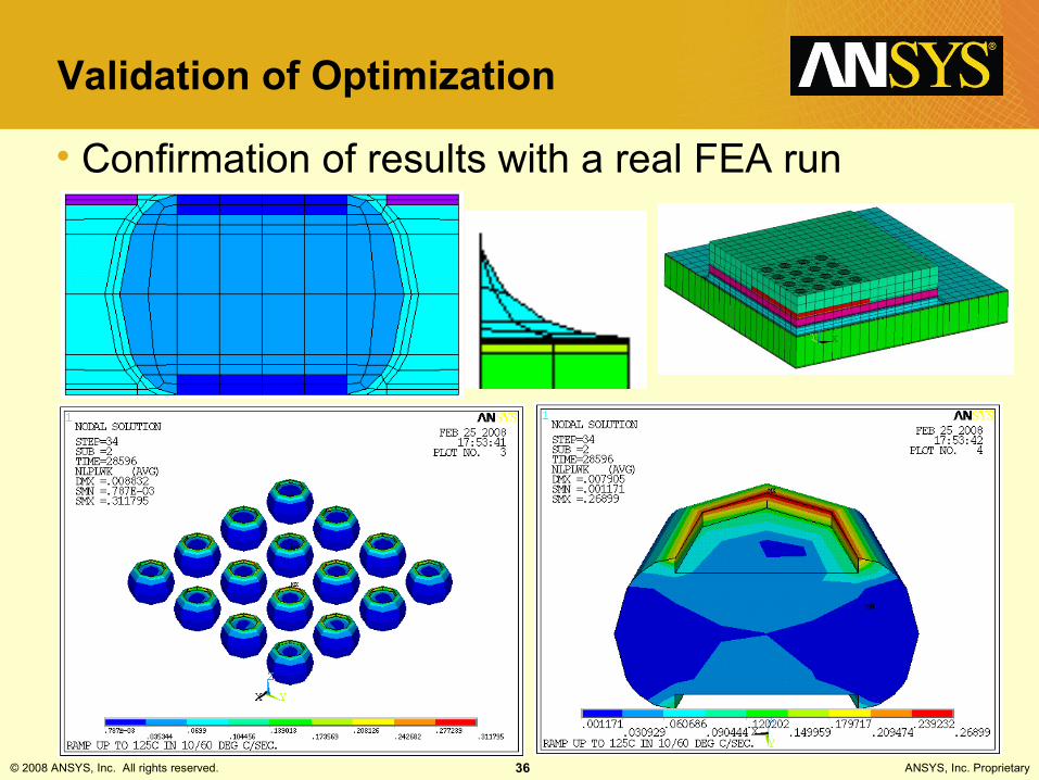
Validation of Optimization
• Confirmation of results with a real FEA run

© 2008 ANSYS, Inc. All rights reserved. 37 ANSYS, Inc. Proprietary
Conclusions
• 2D APDL model – Benefits:
• very fast simulations• critical input variables validated by 3D model
– Drawbacks:• wrong correlation between objectives
• 3D APDL model– Benefits:
• more reliable• conflict evidences between the objectives of the optimisation• material properties vs geometric parameters• presence of underfill is critical
– Drawbacks:• slower simulations• meshing difficulties
© 2008 ANSYS, Inc. All rights reserved. 38 ANSYS, Inc. Proprietary
Conclusions
• Where do we use modeFrontier in our day-to-day simulation practice?– Matching Experimental Data by varying of material and geometric input data within
tolerance values:• Thermo-couple readings• Displacements of Moire Measurements• ...
– Performing DOE studies to understand main effects of critical parameters• Finding the best underfill material for reliability• ...
– Getting the best solution for reliability using multi objective optimization• Optimization for minimum plastic work• Optimization for minimum shear strains/stresses
– Six-Sigma Studies for variations in materials• Effect of glass transition temperature variation of underfills• Effect of modulus variation of underfills• ...


