1
2018 University of Cincinnati SAE Baja – Rear Suspension
A Baccalaureate thesis submitted to the
Department of Mechanical and Materials Engineering College of Engineering and Applied Science
University of Cincinnati
in partial fulfillment of the requirements for the degree of
Bachelor of Science
in Mechanical Engineering Technology
by
Gabriel Archer
April 2018
Thesis Advisor:
Dean Allen Arthur
2018 University of Cincinnati Baja Gabe Archer
2
TABLE OF CONTENTS
TABLE OF CONTENTS .......................................................................................................... 2
ROBLEM DEFINITION AND RESEARCH ........................................................................... 3
PROBLEM STATEMENT .................................................................................................................................... 3 BACKGROUND ................................................................................................................................................ 3
RESEARCH .............................................................................................................................. 4
SCOPE OF THE PROBLEM ................................................................................................................................. 4 CURRENT STATE OF THE ART .......................................................................................................................... 4 END USER ...................................................................................................................................................... 5 CONCLUSIONS AND SUMMARY OF RESEARCH ................................................................................................. 5
CUSTOMER FEATURES........................................................................................................ 5
PRODUCT OBJECTIVES ....................................................................................................... 6
DESIGN ALTERNATIVES AND SELECTION .................................................................... 7
LOADING CONDITIONS ................................................................................................................................... 9 FEA .............................................................................................................................................................. 9
CALCULATIONS .................................................................................................................. 10
MANUFACTURING ............................................................................................................. 11
RESULTS ............................................................................................................................... 13
PROJECT MANAGEMENT .................................................................................................. 14
BUDGET, PROPOSED/ACTUAL ....................................................................................................................... 14 PROPOSED SCHEDULE .................................................................................................................................. 14 ACTUAL SCHEDULE ..................................................................................................................................... 15
CONTACT .............................................................................................................................. 16
WORKS CITED ..................................................................................................................... 16
2018 University of Cincinnati Baja Gabe Archer
3
ABSTRACT
The University of Cincinnati Baja SAE team competes against schools across the country by
designing, building, and racing Baja type vehicles. This report will go through the redesigned
rear suspension of the previous years (2017) Baja vehicle. With a desired outcome of this
project being to provide a suspension solution that would perform better than the previous
design. This report will go into detail about the design selection, manufacturing and results
ROBLEM DEFINITION AND RESEARCH
PROBLEM STATEMENT
The #6 University of Cincinnati Baja car currently has many different flaws in its design. As
it sits now the rear suspension allows both rear axles to slide out of the rear differential as the
suspension flexes. The current ground clearance for the car is far below the desired height
that is needed for competition. We are unable to fit all team members into the current car
under SAE Baja regulation, this will have to be addressed as well.
BACKGROUND
The goal in Baja SAE is to design, build and race off-road vehicles that can withstand
elements of rough terrain against many different colleges around the country. These vehicles
are often similar in appearance to dune buggies with large tires and a complete role cage that
completely protects the driver. One main component of these cars is the suspension which
allows for the cars to travel over rough terrain at high speeds by conforming to the terrain.
This is made possible by combining long wheel travel, high ground clearance, strong
structural frame ect.
The University of Cincinnati currently has three cars that are in various stages of their life.
The most recent is the #6 car which currently sits as a completed car however it has never
been certified for competition and has many design flaws. The remaining two completed cars
are both still fully functional and certified, which will serve as great models for testing.
We are proposing a redesign of multiple aspects of the #6 Baja car that include but not
limited to; front and rear suspension, cage design, ergonomics and a dynamometer. These
improvements are needed for the car to be fully capable within the requirements for the 2018
SAE Baja competition. These will be completed in time for the Spring 2018 competition
where we will have the car certified for competition, as well as be competing.
2018 University of Cincinnati Baja Gabe Archer
4
RESEARCH
SCOPE OF THE PROBLEM
The problem with the #6 Baja is that the current design of the car does not meet the
requirements of the Baja SAE 2018. This problem is being addressed so the Baja team will
be able to compete in the 2018 competition in Maryland. Each individual project is important
due to the car needing to meet the requirements given in the Baja SAE Collegiate Design
Series 2018 Rules (1) to be certified to compete.
CURRENT STATE OF THE ART
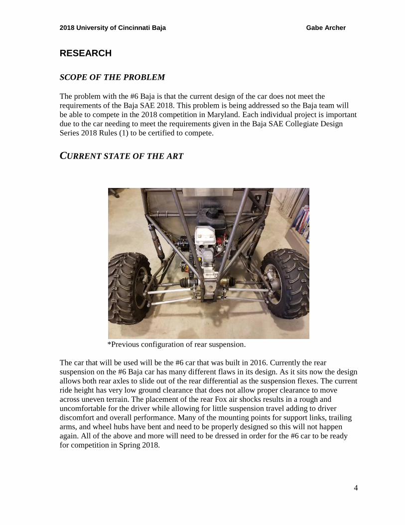
*Previous configuration of rear suspension.
The car that will be used will be the #6 car that was built in 2016. Currently the rear
suspension on the #6 Baja car has many different flaws in its design. As it sits now the design
allows both rear axles to slide out of the rear differential as the suspension flexes. The current
ride height has very low ground clearance that does not allow proper clearance to move
across uneven terrain. The placement of the rear Fox air shocks results in a rough and
uncomfortable for the driver while allowing for little suspension travel adding to driver
discomfort and overall performance. Many of the mounting points for support links, trailing
arms, and wheel hubs have bent and need to be properly designed so this will not happen
again. All of the above and more will need to be dressed in order for the #6 car to be ready
for competition in Spring 2018.
2018 University of Cincinnati Baja Gabe Archer
5
END USER
The objective of BAJA SAE is to not only design a car competitive for competition, but to
design it for the recreational user market. We are competing to have our car selected for
manufacture by a fictitious firm. The prototype vehicle needs to demonstrate reliability,
ergonomics, and competitiveness all while being economically valuable for manufacture and
profitability by the fictitious firm.
The end user of the car will be the 2018 UC Baja team competing at the Maryland
competition in April. Here we will be judged on acceleration, hill Climb, maneuverability
and suspension. The car must be able to pass all tests without failures to prove reliability. On
top of the physical events, we are also graded on our engineering design though both a
submitted design report and on-site evaluation of the car. (1)
The rear suspension will have to be designed to pass or exceed each of the test specified
by the SAE Baja rulebook. This includes but not limited to; sufficient ground clearance to
clear obstacles, proper rebound and spring rates to allow fast movement over uneven terrain
and ease of maintenance/replacement parts.
CONCLUSIONS AND SUMMARY OF RESEARCH
As the 2018 University of Cincinnati Baja team we are going to address the stated problems
above. Each of these issues will be addressed individually with different team members, each
member’s projects are listed below. Each project was chosen to complete an integral part that
is needed to compete in the 2018 competition. (1)
I am proposing a complete redesign of the rear suspension of the #6 car that will address
and fix the issues stated above. This will be completed in time for the Spring 2018
competition and will be key in getting the #6 car ready to be certified for competition.
CUSTOMER FEATURES
Weighted importance of design specifications:
0.1 - Safety
0.25 - Suspension travel
0.2 - Ground Clearance
0.15 - Weight
0.15 - Reliability
0.1 - Maintenance/Ease of Replacement
0.05 - Cost
2018 University of Cincinnati Baja Gabe Archer
6
PRODUCT OBJECTIVES
• Safety
o Design will adhere to SAE rules
o Specifications will consider the weight of the driver up to 250lbs
• Suspension travel
o Utilization of new Bilstein XVA Shocks adjustability
o Improved shock travel from ~2” to ~6.5”
o Have desired ride height not be at bottom of shock limit to allow for more
rebound.
o Fully independent
• Ground Clearance
o Ground clearance at ride height will be 11.5” from the center of the rear end to
bring closer to where other cars are at.
• Reliability
o Design must hold up to 2018 competition
o Must account for the weight of different riders
o Robust while keeping weight down to a minimum
• Maintenance/Ease of Replacement
o Use of standard parts as much as possible
o Each side be independent from on another
o Use of standard tools as often as possible
• Cost
o Must not exceed given Baja budget
o Receiving sponsorship from Bilstein for new coil over shocks
2018 University of Cincinnati Baja Gabe Archer
7
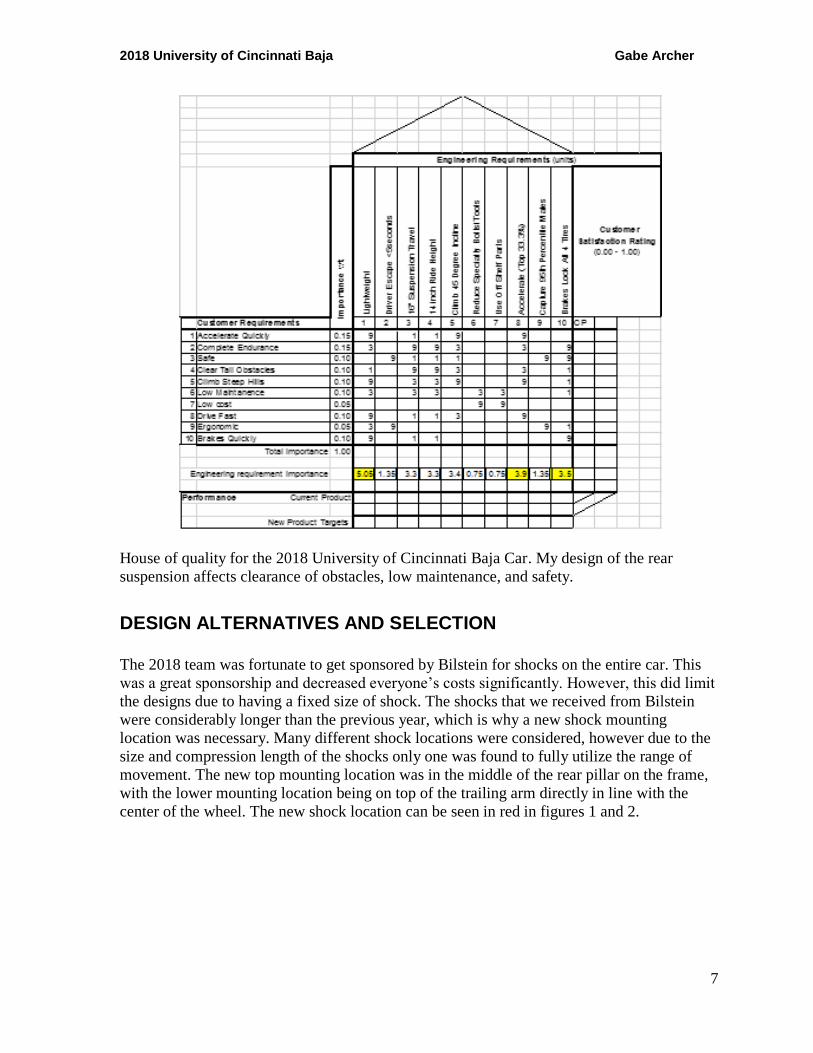
House of quality for the 2018 University of Cincinnati Baja Car. My design of the rear
suspension affects clearance of obstacles, low maintenance, and safety.
DESIGN ALTERNATIVES AND SELECTION The 2018 team was fortunate to get sponsored by Bilstein for shocks on the entire car. This
was a great sponsorship and decreased everyone’s costs significantly. However, this did limit
the designs due to having a fixed size of shock. The shocks that we received from Bilstein
were considerably longer than the previous year, which is why a new shock mounting
location was necessary. Many different shock locations were considered, however due to the
size and compression length of the shocks only one was found to fully utilize the range of
movement. The new top mounting location was in the middle of the rear pillar on the frame,
with the lower mounting location being on top of the trailing arm directly in line with the
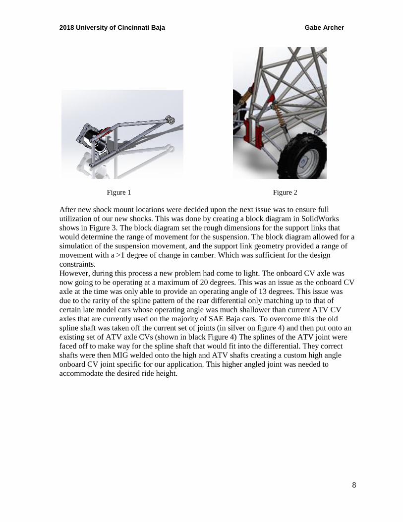
center of the wheel. The new shock location can be seen in red in figures 1 and 2.
2018 University of Cincinnati Baja Gabe Archer
8
Figure 1 Figure 2
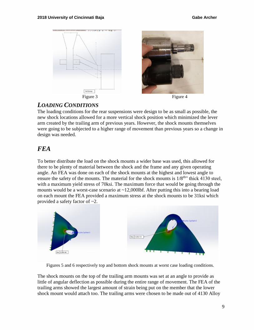
After new shock mount locations were decided upon the next issue was to ensure full
utilization of our new shocks. This was done by creating a block diagram in SolidWorks
shows in Figure 3. The block diagram set the rough dimensions for the support links that
would determine the range of movement for the suspension. The block diagram allowed for a
simulation of the suspension movement, and the support link geometry provided a range of
movement with a >1 degree of change in camber. Which was sufficient for the design
constraints.
However, during this process a new problem had come to light. The onboard CV axle was
now going to be operating at a maximum of 20 degrees. This was an issue as the onboard CV
axle at the time was only able to provide an operating angle of 13 degrees. This issue was
due to the rarity of the spline pattern of the rear differential only matching up to that of
certain late model cars whose operating angle was much shallower than current ATV CV
axles that are currently used on the majority of SAE Baja cars. To overcome this the old
spline shaft was taken off the current set of joints (in silver on figure 4) and then put onto an
existing set of ATV axle CVs (shown in black Figure 4) The splines of the ATV joint were
faced off to make way for the spline shaft that would fit into the differential. They correct
shafts were then MIG welded onto the high and ATV shafts creating a custom high angle
onboard CV joint specific for our application. This higher angled joint was needed to
accommodate the desired ride height.
2018 University of Cincinnati Baja Gabe Archer
9
Figure 3 Figure 4
LOADING CONDITIONS The loading conditions for the rear suspensions were design to be as small as possible, the
new shock locations allowed for a more vertical shock position which minimized the lever
arm created by the trailing arm of previous years. However, the shock mounts themselves
were going to be subjected to a higher range of movement than previous years so a change in
design was needed.
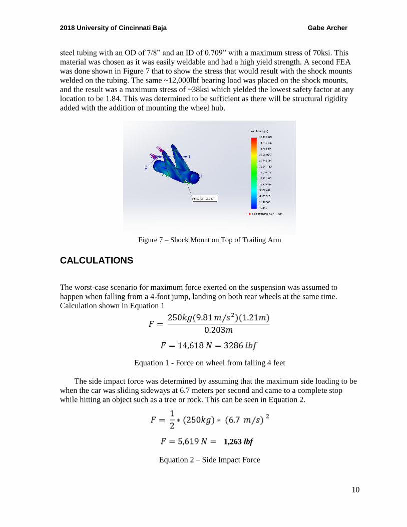
FEA
To better distribute the load on the shock mounts a wider base was used, this allowed for
there to be plenty of material between the shock and the frame and any given operating
angle. An FEA was done on each of the shock mounts at the highest and lowest angle to
ensure the safety of the mounts. The material for the shock mounts is 1/8th” thick 4130 steel,
with a maximum yield stress of 70ksi. The maximum force that would be going through the
mounts would be a worst-case scenario at ~12,000lbf. After putting this into a bearing load
on each mount the FEA provided a maximum stress at the shock mounts to be 31ksi which
provided a safety factor of ~2.
Figures 5 and 6 respectively top and bottom shock mounts at worst case loading conditions.
The shock mounts on the top of the trailing arm mounts was set at an angle to provide as
little of angular deflection as possible during the entire range of movement. The FEA of the
trailing arms showed the largest amount of strain being put on the member that the lower
shock mount would attach too. The trailing arms were chosen to be made out of 4130 Alloy
2018 University of Cincinnati Baja Gabe Archer
10
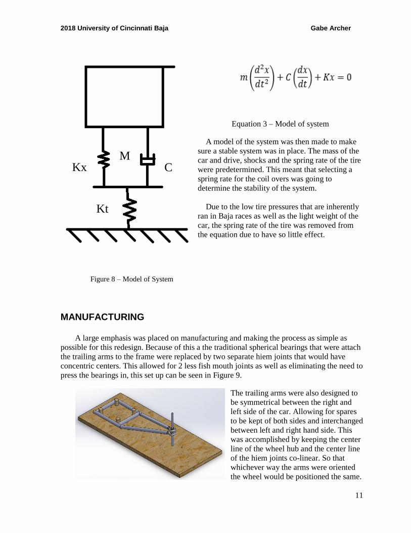
steel tubing with an OD of 7/8” and an ID of 0.709” with a maximum stress of 70ksi. This
material was chosen as it was easily weldable and had a high yield strength. A second FEA
was done shown in Figure 7 that to show the stress that would result with the shock mounts
welded on the tubing. The same ~12,000lbf bearing load was placed on the shock mounts,
and the result was a maximum stress of ~38ksi which yielded the lowest safety factor at any
location to be 1.84. This was determined to be sufficient as there will be structural rigidity
added with the addition of mounting the wheel hub.
Figure 7 – Shock Mount on Top of Trailing Arm
CALCULATIONS
The worst-case scenario for maximum force exerted on the suspension was assumed to
happen when falling from a 4-foot jump, landing on both rear wheels at the same time.
Calculation shown in Equation 1
Equation 1 - Force on wheel from falling 4 feet
The side impact force was determined by assuming that the maximum side loading to be
when the car was sliding sideways at 6.7 meters per second and came to a complete stop
while hitting an object such as a tree or rock. This can be seen in Equation 2.
Equation 2 – Side Impact Force
1,263 lbf
2018 University of Cincinnati Baja Gabe Archer
11
Equation 3 – Model of system
A model of the system was then made to make
sure a stable system was in place. The mass of the
car and drive, shocks and the spring rate of the tire
were predetermined. This meant that selecting a
spring rate for the coil overs was going to
determine the stability of the system.
Due to the low tire pressures that are inherently
ran in Baja races as well as the light weight of the
car, the spring rate of the tire was removed from
the equation due to have so little effect.
Figure 8 – Model of System
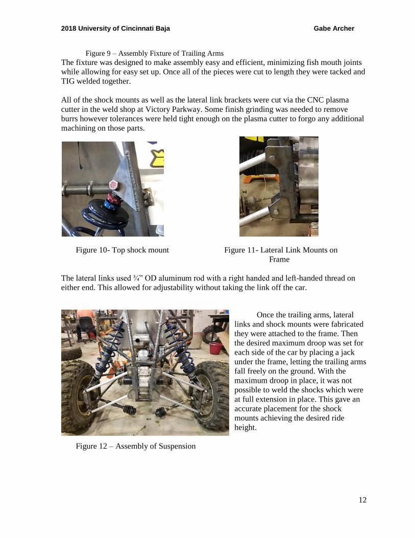
MANUFACTURING A large emphasis was placed on manufacturing and making the process as simple as
possible for this redesign. Because of this a the traditional spherical bearings that were attach
the trailing arms to the frame were replaced by two separate hiem joints that would have
concentric centers. This allowed for 2 less fish mouth joints as well as eliminating the need to
press the bearings in, this set up can be seen in Figure 9.
The trailing arms were also designed to
be symmetrical between the right and
left side of the car. Allowing for spares
to be kept of both sides and interchanged
between left and right hand side. This
was accomplished by keeping the center
line of the wheel hub and the center line
of the hiem joints co-linear. So that
whichever way the arms were oriented
the wheel would be positioned the same.
M C Kx
Kt
2018 University of Cincinnati Baja Gabe Archer
12
Figure 9 – Assembly Fixture of Trailing Arms
The fixture was designed to make assembly easy and efficient, minimizing fish mouth joints
while allowing for easy set up. Once all of the pieces were cut to length they were tacked and
TIG welded together.
All of the shock mounts as well as the lateral link brackets were cut via the CNC plasma
cutter in the weld shop at Victory Parkway. Some finish grinding was needed to remove
burrs however tolerances were held tight enough on the plasma cutter to forgo any additional
machining on those parts.
Figure 10- Top shock mount Figure 11- Lateral Link Mounts on
Frame
The lateral links used ¾” OD aluminum rod with a right handed and left-handed thread on
either end. This allowed for adjustability without taking the link off the car.
Once the trailing arms, lateral
links and shock mounts were fabricated
they were attached to the frame. Then
the desired maximum droop was set for
each side of the car by placing a jack
under the frame, letting the trailing arms
fall freely on the ground. With the
maximum droop in place, it was not
possible to weld the shocks which were
at full extension in place. This gave an
accurate placement for the shock
mounts achieving the desired ride
height.
Figure 12 – Assembly of Suspension
2018 University of Cincinnati Baja Gabe Archer
13
RESULTS
The final assembly of the rear suspension was successful, a ride height of 11.5 was
established along with a wheel base of 54”. The wheel travel was unable to be completely
tested due to an over calculation of spring rate. We were able to get a wheel travel of 8”
however, with still ~2.5” of travel left in the shocks a lighter weight spring should bring this
up to the desired 10.5” The weight of the system did end up a few pounds heavier than the
previous suspensions, this was due to the use of coil overs which are inherently heavier than
air shocks that were previously used. Due to the increase in adjustability and performance we
receive from the coil overs, this extra was justified.
The original plan to test the suspension was going to be a drop test from 4 ft. Where the
rear wheels would both hit simultaneously while the front wheels were 1.5 feet higher than
the rear, simulating a jump. A strain gauge would read the maximum stress on the shock
mounts which we could then derive the force and compare it to the calculated force.
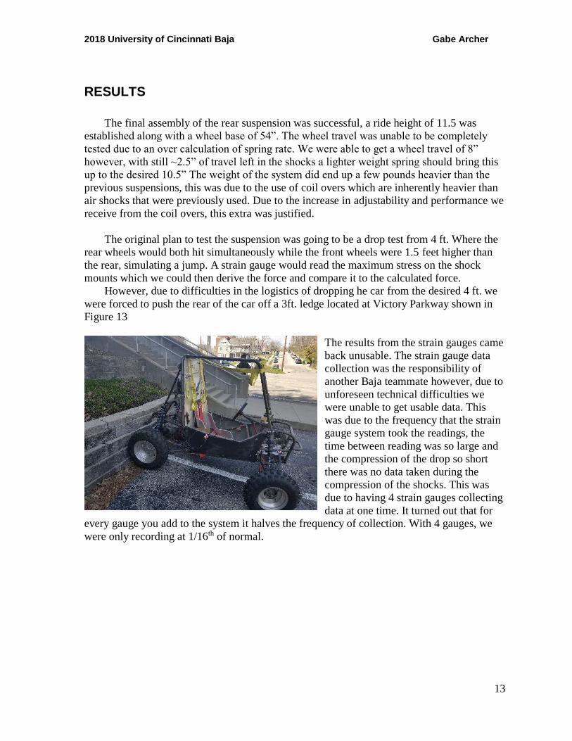
However, due to difficulties in the logistics of dropping he car from the desired 4 ft. we
were forced to push the rear of the car off a 3ft. ledge located at Victory Parkway shown in
Figure 13
The results from the strain gauges came
back unusable. The strain gauge data
collection was the responsibility of
another Baja teammate however, due to
unforeseen technical difficulties we
were unable to get usable data. This
was due to the frequency that the strain
gauge system took the readings, the
time between reading was so large and
the compression of the drop so short
there was no data taken during the
compression of the shocks. This was
due to having 4 strain gauges collecting
data at one time. It turned out that for
every gauge you add to the system it halves the frequency of collection. With 4 gauges, we
were only recording at 1/16th of normal.
2018 University of Cincinnati Baja Gabe Archer
14
PROJECT MANAGEMENT
BUDGET, PROPOSED/ACTUAL
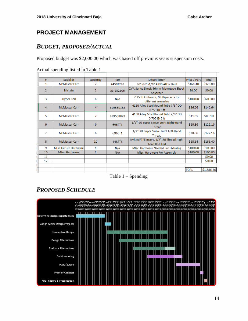
Proposed budget was $2,000.00 which was based off previous years suspension costs.
Actual spending listed in Table 1
Table 1 – Spending
PROPOSED SCHEDULE
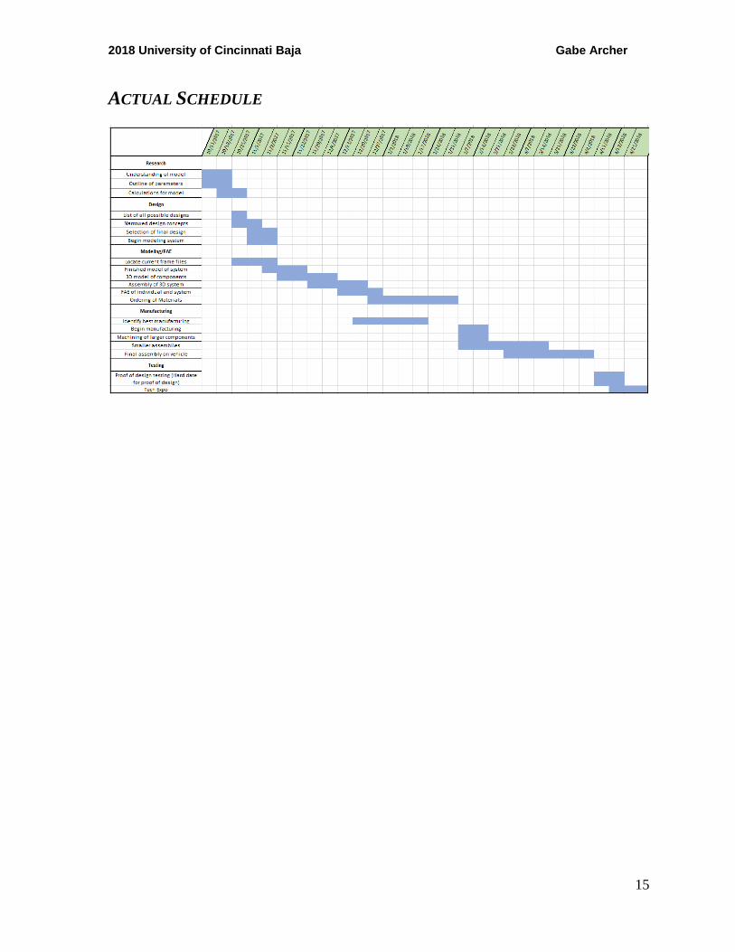
2018 University of Cincinnati Baja Gabe Archer
15
ACTUAL SCHEDULE
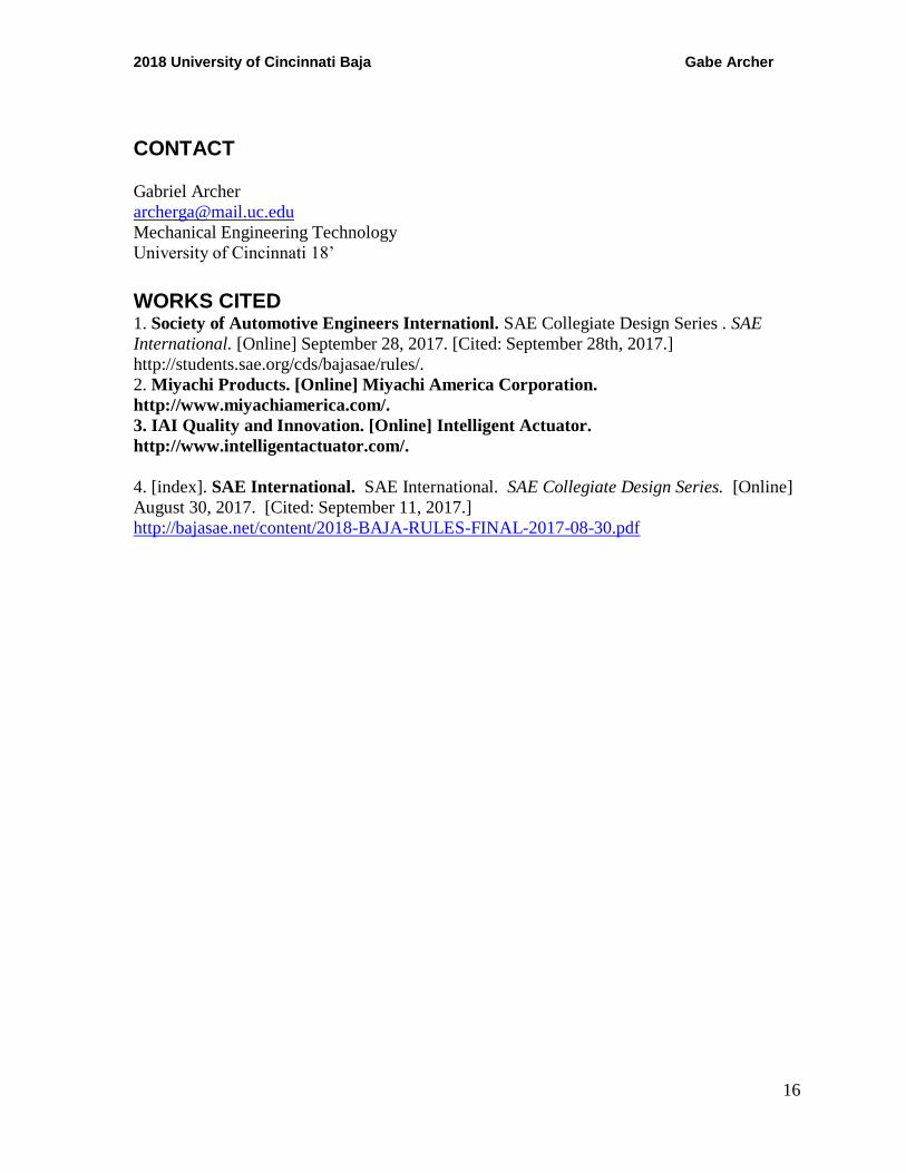
2018 University of Cincinnati Baja Gabe Archer
16
CONTACT
Gabriel Archer
Mechanical Engineering Technology
University of Cincinnati 18’
WORKS CITED 1. Society of Automotive Engineers Internationl. SAE Collegiate Design Series . SAE
International. [Online] September 28, 2017. [Cited: September 28th, 2017.]
http://students.sae.org/cds/bajasae/rules/.
2. Miyachi Products. [Online] Miyachi America Corporation.
http://www.miyachiamerica.com/.
3. IAI Quality and Innovation. [Online] Intelligent Actuator.
http://www.intelligentactuator.com/.
4. [index]. SAE International. SAE International. SAE Collegiate Design Series. [Online]
August 30, 2017. [Cited: September 11, 2017.]
http://bajasae.net/content/2018-BAJA-RULES-FINAL-2017-08-30.pdf


