Download - 2020 NASA AEROSPACE BATTERY WORKSHOP

©, The Ohio State University, 2019
OPTIMAL SENSOR PLACEMENT FOR FAULT
DIAGNOSIS AND ISOLATION IN AEROSPACE
BATTERY PACKS
November 17, 2020
2020 NASA AEROSPACE BATTERY WORKSHOP
DR. MATILDE D’ARPINORESEARCH SCIENTIST
CENTER FOR AUTOMOTIVE RESEARCH
PROF. GIORGIO RIZZONI AND MS. YE CHENG
DEPARTMENT OF MECHANICAL AND AEROSPACE ENGINEERING

2
Outline
1. Motivation
2. Intrinsic properties of SP and PS battery pack configurations
3. Methodology description and single cell example
4. Analysis of traditional sensor set
5. Performing sensor placement to find minimal sensor set that can achieve complete fault isolation
6. Conclusions
Satellites Launch vehiclesMoon/Mars exploration
More Electric Aircraft Electric/Hybrid commercial aviation
UAV/UAM

©, The Ohio State University, 2019
MOTIVATION

4
NASA ULI Electric Propulsion: Challenges and Opportunities
Electric motor
Turbo-shaftand generator
Distributed electric propulsion is a leading architecture for
measurable CO₂ reduction on large commercial aircraft - regional,
single aisle, and twin aisle.
▪ Two turbo-generators to supply electrical power to distributed motors
▪ Eight motors with embedded power electronics
▪ Integrated thermal management system
▪ Battery energy management can be charge-depleting or charge-sustaining;
battery thermal management system is separate from powertrainFelder, J.L., NASA Electric Propulsion System Studies, Report No. GRC-E-DAA-TN28410, 2015, Available at www.nasa.gov. Challenge 1 System Integration
Success Criteria: Vehicle energy and CO2 >20% improvement over existing solutions
Challenge 2 Ultra-High Power Density Electric Machine and Power ElectronicsSuccess Criteria: Electric machines > 14 kW/kg, power electronics > 25 kW/kg, efficiency > 99%, bus voltage up to 2kV without partial discharge
Challenge 3 Energy StorageSuccess Criteria: Power density and reliability (desired 450 Wh/kg)
Challenge 4 Advanced Control of Onboard Electrical Power SystemsSuccess Criteria: System remains stable at 20% voltage sag and 200% step load change
Challenge 5 Research Infrastructure for More Electric AircraftsSuccess Criteria: Sub-system and component prototyping and testing at elevation – 2 kV, 1 MW, 20 kRPM drive tests
Research on thermal management system design is integrated in every aspectof the project.
Perullo, C., Alahmad, A., Wen, J., D'Arpino, M., Canova, M., Mavris, D. N., & Benzakein, M. J. (2019). Sizing and Performance Analysis of a Turbo-Hybrid-Electric Regional Jet for the NASA ULI Program. In AIAA Propulsion and Energy 2019 Forum (p. 4490).
Hybrid Turboelectric

5
NASA ULI Electric Propulsion: Challenges and Opportunities
Cell Cell 1 Cell 2 Cell 6 Cell 7 Cell 8 Cell 9
Format 18650 Cylindrical Pouch
Chemistry LMO NMC NMC Li-Si Li-Metal Li-S
Capacity assessment [Ah] (@1C, 23⁰C)
3.25 2.85 10.87 10.24 (19.40) (14.7)
Energy Density assessment [Wh/kg] (@1C, 23⁰C)
237 215 224 336 (478) (363)
Experimentally Tested? Yes No No
Δ𝑆𝑜𝐶𝑎𝑣𝑎𝑖𝑙 (10-95)%
𝑚𝑒𝑛𝑒 - Total Cell Number176,472
(516s x 342p)196,560
(504s x 390p)51,816
(508s x 102p)54,752
(472s x 116p)27,608
(476s x 58p)66,990
(770s x 87p)
Max C-rate (discharge) 2.20 2.26 2.16 2.15 2.28 2.06
Heat Generation (kW)(Peak/Average)
672 / 66 357 / 42 438 / 41 330 / 24 74 / 7 -
Efficiency [%](Min/Average)
88 / 97 90 / 97 92 / 98 94 / 98 94 / 98 -
Pack Weight (Tons) 8.39 9.26 8.88 5.91 4.16 5.69
Design of a 2MWh battery pack for the 600nmi. 30% climb – 20% cruise mission profile.
Sergent, A., Ramunno, M., D'Arpino, M., Canova, M., & Perullo, C. (2020). Optimal Sizing and Control of Battery Energy Storage Systems for Hybrid Turboelectric Aircraft (No. 2020-01-0050). SAE Technical Paper.

6
Definition of design optimization problem for large scale battery packs
𝒏S𝒎P 𝒎P𝒏S
𝐼𝑀
𝑉𝑀
11
⋮
𝑖1
𝑛1
⋮
1j
⋮
𝑖𝑗
𝑛j
⋮
11
⋮
𝑖1
𝑛𝑚
⋮
System-level TMS and BMS
Unit1,2
Unit1,j
Unit1, n
Unit1,1
Uniti,2
Uniti,j
Uniti, n
Uniti,1
Unit m,2
Unitm,j
Unitm, n
Unitm,1
𝐼𝑀
𝑉𝑀
11 ⋯ ⋯1𝑗 1𝑚
𝑖1 ⋯ ⋯𝑖𝑗 i𝑚
𝑛1 ⋯ ⋯n𝑗 𝑛𝑚
Assumption: cell selection and pack sizing has already taken place (see presentation on Thursday ‘A COMPARATIVE STUDY OF LI-ION BATTERY TECHNOLOGIES FOR HYBRID-ELECTRIC REGIONAL
AIRCRAFT APPLICATIONS’
Basic Unit Design and SizingPack Design
Design parameters1. Architecture – SP vs. PS in different
modular configurations.2. Type, number and location of sensors3. Balancing (if passive, answer is unique for
each architecture, if active there are more options)
4. Protection device sizing and placement
Design parameters1. Architecture – SP, PS and combinations.2. Type, number and location of sensors3. Protection device sizing and placement
Design objectives: $ cost, Diagnostic capabilities, Reliability, Adaptability to component variation, ……
𝑉𝐵𝑃

7
Battery pack configurations
NASA ULI Hybrid turbo electric configuration require a large number of cells (10-100 of thousands of cells) interconnected together to access to the additional fuel burn reduction (up to 20% compared to turboelectric)
There are two main configurations for battery pack modules (SP and PS)
𝒏S𝒎P
Series of
parallel cells
𝒎P𝒏S
Parallel of series
connected cells
𝐼𝐵𝑃
Module 1
𝑉𝐵𝑃
11
⋮
𝑖1
𝑛1
⋮
𝐼1𝑀
𝑉1𝑀
Module 𝑗
1j
⋮
𝑖𝑗
𝑛j
⋮
𝐼𝑗𝑀
𝑉𝑗𝑀
Module 𝑚
1𝑚
⋮
𝑖𝑚
𝑛𝑚
⋮
𝐼𝑚𝑀
𝑉𝑚𝑀
Module
1M
odule
𝐼𝐵𝑃
𝑉𝐵𝑃
Module
11 ⋯ ⋯1𝑗 1𝑚
𝑖1 ⋯ ⋯𝑖𝑗 i𝑚
𝑛1 ⋯ ⋯n𝑗 𝑛𝑚
𝐼1𝑀
𝐼𝑖𝑀
𝐼𝑛𝑀
𝑉1𝑀
𝑉𝑖𝑀
𝑉𝑛𝑀
1. Explore the intrinsic properties of battery module architectures (SP and PS)2. Effects of current and voltage unbalance considering
1. Capacity and resistance unbalance2. Short circuit (this will affect the sizing/selection of protective devices)
3. Sensor requirements for faults detectability and isolabilily (traditional vs optimal) (this will affect the selection of sensor set)
Cai, Y., Cancian, M., D’Arpino, M., & Rizzoni, G. (2019, July). A generalized equivalent circuit model for large-scale battery packs with cell-to-cell variation. In 2019 IEEE National Aerospace and Electronics Conference (NAECON) (pp. 24-30). IEEE.

8
INTRINSIC PROPERTIES OF SP AND PS
9
Battery modeling - Two architectures are commonly consideredM
odule
1M
od
ule
𝐼𝐵𝑃
𝑉𝐵𝑃
Module
𝑉11 11 ⋯ ⋯𝑉1j
𝐼1𝑗𝐼11 𝐼1𝑚
𝑉1𝑚1𝑗 1𝑚
𝑉𝑖1 𝑖1 ⋯ ⋯𝑉𝑖j
𝐼𝑖𝑗𝐼𝑖1 𝐼𝑖𝑚
𝑉𝑖𝑚𝑖𝑗 i𝑚
𝑉𝑛1 𝑛1 ⋯ ⋯𝑉𝑛𝑗
𝐼𝑛𝑗𝐼𝑛1 𝐼𝑛𝑚
𝑉𝑛𝑚n𝑗 𝑛𝑚
𝐼1𝑀
𝐼𝑖𝑀
𝐼𝑛𝑀
𝑉1𝑀
𝑉𝑖𝑀
𝑉𝑛𝑀
𝐼𝐵𝑃
Module 1
𝑉𝐵𝑃
𝑉1111
𝐼11
⋮
𝑉𝑖1 𝑖1
𝑉𝑛1 𝑛1
⋮
𝐼𝑖1
𝐼𝑛1
𝐼1𝑀
𝑉1𝑀
Module 𝑗
𝑉1𝑗1j
𝐼1𝑗
⋮
𝑉𝑖𝑗 𝑖𝑗
𝑉𝑛𝑗 𝑛j
⋮
𝐼𝑖𝑗
𝐼𝑛𝑗
𝐼𝑗𝑀
𝑉𝑗𝑀
Module 𝑚
𝑉1𝑚 1𝑚
𝐼1𝑚
⋮
𝑉𝑖𝑚 𝑖𝑚
𝑉𝑛𝑚 𝑛𝑚
⋮
𝐼𝑖𝑚
𝐼𝑛𝑚
𝐼𝑚𝑀
𝑉𝑚𝑀
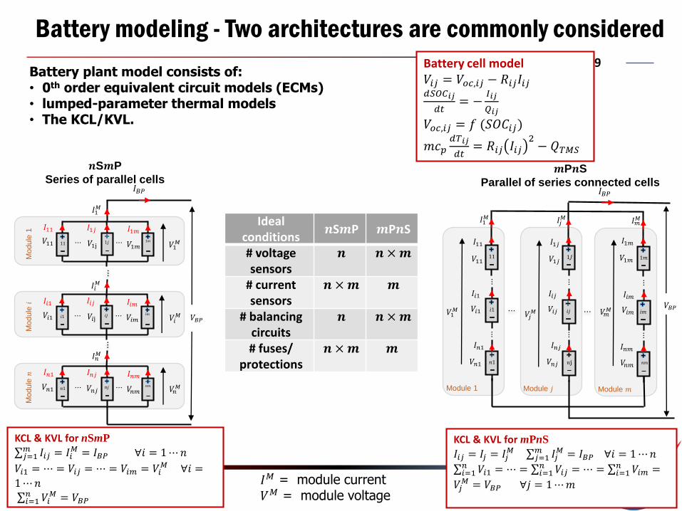
Battery cell model𝑉𝑖𝑗 = 𝑉𝑜𝑐,𝑖𝑗 − 𝑅𝑖𝑗𝐼𝑖𝑗𝑑𝑆𝑂𝐶𝑖𝑗
𝑑𝑡= −
𝐼𝑖𝑗
𝑄𝑖𝑗
𝑉𝑜𝑐,𝑖𝑗 = 𝑓 (𝑆𝑂𝐶𝑖𝑗)
𝑚𝑐𝑝𝑑𝑇𝑖𝑗
𝑑𝑡= 𝑅𝑖𝑗 𝐼𝑖𝑗
2− 𝑄𝑇𝑀𝑆
𝐼𝑀 = module current𝑉𝑀 = module voltage
KCL & KVL for nSmP
σ𝑗=1𝑚 𝐼𝑖𝑗 = 𝐼𝑖
𝑀 = 𝐼𝐵𝑃 ∀𝑖 = 1⋯𝑛
𝑉𝑖1 = ⋯ = 𝑉𝑖𝑗 = ⋯ = 𝑉𝑖𝑚 = 𝑉𝑖𝑀 ∀𝑖 =
1⋯𝑛σ𝑖=1𝑛 𝑉𝑖
𝑀 = 𝑉𝐵𝑃
KCL & KVL for mPnS
𝐼𝑖𝑗 = 𝐼𝑗 = 𝐼𝑗𝑀 σ𝑗=1
𝑚 𝐼𝑗𝑀 = 𝐼𝐵𝑃 ∀𝑖 = 1⋯𝑛
σ𝑖=1𝑛 𝑉𝑖1 = ⋯ = σ𝑖=1
𝑛 𝑉𝑖𝑗 = ⋯ = σ𝑖=1𝑛 𝑉𝑖𝑚 =
𝑉𝑗𝑀 = 𝑉𝐵𝑃 ∀𝑗 = 1⋯𝑚
Battery plant model consists of: • 0th order equivalent circuit models (ECMs) • lumped-parameter thermal models • The KCL/KVL.
𝒏S𝒎P
Series of parallel cells𝒎P𝒏S
Parallel of series connected cells
Idealconditions
𝒏S𝒎P 𝒎P𝒏S
# voltage sensors
𝒏 𝒏 ×𝒎
# current sensors
𝒏 ×𝒎 𝒎
# balancing circuits
𝒏 𝒏 ×𝒎
# fuses/ protections
𝒏 ×𝒎 𝒎

10
Battery Pack Architecture comparison using Bipartite GraphM
odule
1M
odule
2
V11 V21
V12 V22
Iα12 α22
α11 α21
V11 V21
V12 V22
Iα12 α22
α11 α21
𝐼21 𝐼22
V11 V21
V12 V22
Iα12 α22
α11 α21
V11 V21
V12 V22
Iα12 α22
α11 α21
𝐼11 𝐼12
𝐼𝑀1
𝐼𝐵𝑃
𝐼𝑀2
𝑉11 𝑉12 𝑉𝑀1
𝑉𝑀2𝑉21 𝑉22
𝑉𝐵𝑃
Module 1 Module 2
V11 V21
V12 V22
Iα12 α22
α11 α21
𝑉11
V11 V21
V12 V22
Iα12 α22
α11 α21
𝑉21
V11 V21
V12 V22
Iα12 α22
α11 α21
V11 V21
V12 V22
Iα12 α22
α11 α21
𝑉22
𝑉12
𝐼11 𝐼12
𝐼21 𝐼22
𝐼𝑀1 𝐼𝑀2
𝑉𝑀1 𝑉𝑀2
𝐼𝐵𝑃
𝑉𝐵𝑃
Mo
du
le 1
Mo
du
le 2
𝐼11
𝑐𝑒𝑙𝑙11
𝑉𝑀1
𝐼21
𝑐𝑒𝑙𝑙21
𝑉𝑀2
𝐼12 𝐼22
𝐼𝐵𝑃
𝑉𝐵𝑃
𝑉11 𝑉12
𝐼𝑀1
𝑉21 𝑉22
𝐼𝑀2
𝑐1 𝑐2
𝑐𝐵𝑃
𝒏S𝒎PSeries of parallel cells
Mo
du
le 1
Mo
du
le 2
𝑐𝑒𝑙𝑙11
𝑉11
𝐼𝐵𝑃
𝑉21
𝐼𝑀2
𝑐𝑒𝑙𝑙12
𝑉12 𝑉22
𝑐𝑒𝑙𝑙22
𝑉𝐵𝑃
𝐼11 𝐼12𝐼21 𝐼22
𝑉𝑀2
𝑐1𝑐2
𝑐𝐵𝑃 𝒎P𝒏SParallel of series connected cells
Variables in a green box are equal to each other in ideal case (if the cells
are equals and have the same temperature).
Think Line represents a sum (constraint). The sum is always true, but the element of the summation can be unbalanced due to parameters variation.
Thin Line connects variable those are always equal.
Bipartite Graph is a graphical representation of a model and it is used to analyze the connection between known variables, unknown variables, and faults.

11
Battery Pack Architecture comparison using Bipartite Graph
Module 1:𝑐𝑒𝑙𝑙11 has a problem →𝐼11 ≠ 𝐼12 imbalance → 𝑉𝑀1 ≠ 𝑉𝑀2 unbalance
Module 2:𝐼21 = 𝐼22 not affected.𝑉𝑀2 is not affected.
Pack:𝐼𝐵𝑃 fixed (requirement)𝐼𝑀1=𝐼𝑀2 not affected𝑉𝐵𝑃 affected
The fault of one cell is kept inside the module, however the entity of the current imbalance is high due to the limited impedance of the strings
Pack:𝐼𝐵𝑃 fixed (requirement)𝐼𝑀1 ≠ 𝐼𝑀2 imbalance→ 𝑉𝑀1 =𝑉𝑀2 affected→ 𝑉𝐵𝑃 affected.
Module 1:𝑐𝑒𝑙𝑙11 has a problem→𝐼𝑀1 = 𝐼11 = 𝐼21 is always true → 𝑉11 ≠ 𝑉21 imbalance → 𝑉𝑀1
affected
Module 2:𝐼𝑀2 = 𝐼12 = 𝐼22 is always true, but different current → 𝑉12 =𝑉22 affected → 𝑉𝑀2 affected
The fault of a cell affect all the pack, however the entity of the current imbalance is lower due to the high impedance of the strings
Module
1M
odule
2
V11 V21
V12 V22
Iα12 α22
α11 α21
V11 V21
V12 V22
Iα12 α22
α11 α21
𝐼21 𝐼22
V11 V21
V12 V22
Iα12 α22
α11 α21
V11 V21
V12 V22
Iα12 α22
α11 α21
𝐼11 𝐼12
𝐼𝑀1
𝐼𝐵𝑃
𝐼𝑀2
𝑉11 𝑉12 𝑉𝑀1
𝑉𝑀2𝑉21 𝑉22
𝑉𝐵𝑃
Module 1 Module 2
V11 V21
V12 V22
Iα12 α22
α11 α21
𝑉11
V11 V21
V12 V22
Iα12 α22
α11 α21𝑉21
V11 V21
V12 V22
Iα12 α22
α11 α21
V11 V21
V12 V22
Iα12 α22
α11 α21𝑉22
𝑉12
𝐼11 𝐼12
𝐼21 𝐼22
𝐼𝑀1 𝐼𝑀2
𝑉𝑀1 𝑉𝑀2
𝐼𝐵𝑃
𝑉𝐵𝑃
Mo
du
le 1
Mo
du
le 2
𝐼11
𝑐𝑒𝑙𝑙11
𝑉𝑀1
𝐼21
𝑐𝑒𝑙𝑙21
𝑉𝑀2
𝐼12 𝐼22
𝐼𝐵𝑃
𝑉𝐵𝑃
𝑉11 𝑉12
𝐼𝑀1
𝑉21 𝑉22
𝐼𝑀2
𝑐1 𝑐2
𝑐𝐵𝑃
𝒏S𝒎P
Mo
du
le 1
Mo
du
le 2
𝑐𝑒𝑙𝑙11
𝑉11
𝐼𝐵𝑃
𝑉21
𝐼𝑀2
𝑐𝑒𝑙𝑙12
𝑉12 𝑉22
𝑐𝑒𝑙𝑙22
𝑉𝐵𝑃
𝐼11 𝐼12𝐼21 𝐼22
𝑉𝑀2
𝑐1𝑐2
𝑐𝐵𝑃
𝒎P𝒏S
A circle in red represents a cell with problem.
A circle in orange represents a variable is affected seriously.
A circle in green represents a cell is not affected.
A circle in yellow represents a variable is affected but not that seriously as in orange.
12
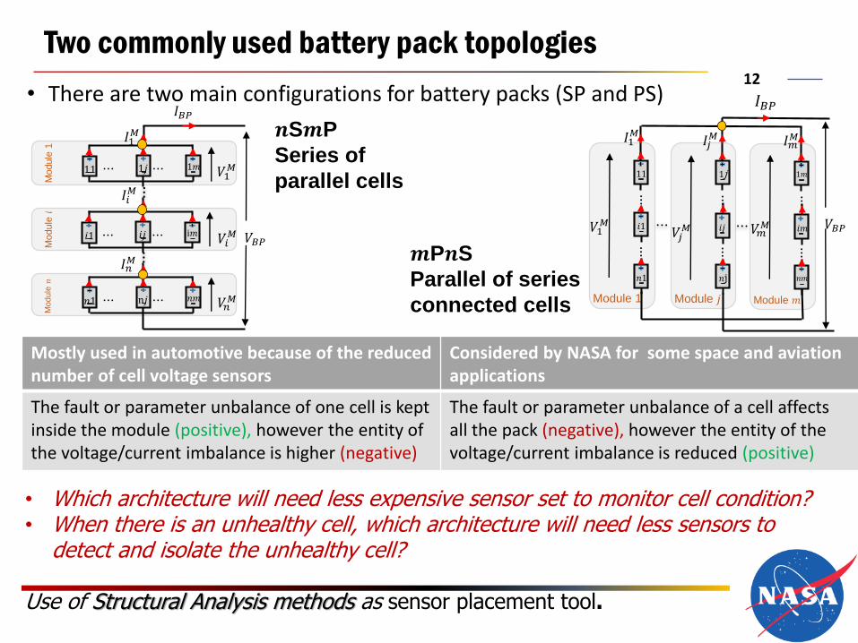
Two commonly used battery pack topologies
• There are two main configurations for battery packs (SP and PS)
Mostly used in automotive because of the reduced number of cell voltage sensors
Considered by NASA for some space and aviation applications
The fault or parameter unbalance of one cell is kept inside the module (positive), however the entity of the voltage/current imbalance is higher (negative)
The fault or parameter unbalance of a cell affects all the pack (negative), however the entity of the voltage/current imbalance is reduced (positive)
𝒏S𝒎P
Series of
parallel cells
𝒎P𝒏S
Parallel of series
connected cells
𝐼𝐵𝑃
Module 1
𝑉𝐵𝑃
11
⋮
𝑖1
𝑛1
⋮
𝐼1𝑀
𝑉1𝑀
Module 𝑗
1j
⋮
𝑖𝑗
𝑛j
⋮
𝐼𝑗𝑀
𝑉𝑗𝑀
Module 𝑚
1𝑚
⋮
𝑖𝑚
𝑛𝑚
⋮
𝐼𝑚𝑀
𝑉𝑚𝑀
Module
1M
odule
𝐼𝐵𝑃
𝑉𝐵𝑃
Module
11 ⋯ ⋯1𝑗 1𝑚
𝑖1 ⋯ ⋯𝑖𝑗 i𝑚
𝑛1 ⋯ ⋯n𝑗 𝑛𝑚
𝐼1𝑀
𝐼𝑖𝑀
𝐼𝑛𝑀
𝑉1𝑀
𝑉𝑖𝑀
𝑉𝑛𝑀
• Which architecture will need less expensive sensor set to monitor cell condition?• When there is an unhealthy cell, which architecture will need less sensors to
detect and isolate the unhealthy cell?
Use of Structural Analysis methods as sensor placement tool.

13
METHODOLOGY DESCRIPTION

14
Plant Equations: (a single cell)
Analytical Model
Incidence Matrix
Equations Unknown variables
𝐼11 𝑉11 𝑉𝑜𝑐11 𝑇11 𝑆𝑜𝐶11
𝑒1 1 1 1 0 0
𝑒2 1 0 0 0 1
𝑒3 0 0 1 0 1
𝑒4 1 0 0 1 0
Structural Model
𝑒1: 𝑉11 = 𝑉𝑜𝑐11 − 𝑅11𝐼11
𝑒2:𝑑𝑆𝑜𝐶11
𝑑𝑡= −
𝐼11
𝑄
𝑒3: 𝑉𝑜𝑐11 = 𝑓(𝑆𝑜𝐶11)
𝑒4: 𝑚𝑐𝑝𝑑𝑇11
𝑑𝑡= 𝑅11 𝐼11
2 − 𝑄𝑇𝑀𝑆11
Toolbox/MATLAB
Eq
ua
tio
ns
Variables
Incidence Matrix
[1] Zhang, J., Yao, H., & Rizzoni, G. (2017). Fault diagnosis for electric drive systems of electrified vehicles based on structural analysis. IEEE Transactions on Vehicular
Technology, 66(2), 1027-1039.
[2] Rahman, B. M. (2019). Sensor Placement for Diagnosis of Large-Scale, Complex Systems: Advancement of Structural Methods (Doctoral dissertation, The Ohio State University).
Definition of Structural Analysis and example for single cell model
• Structural analysis investigates the model
constraint structure, i.e., the connections between
known variables, unknown variables, and faults.
• The connections can be represented through
bipartite graphs or incidence matrices.
15
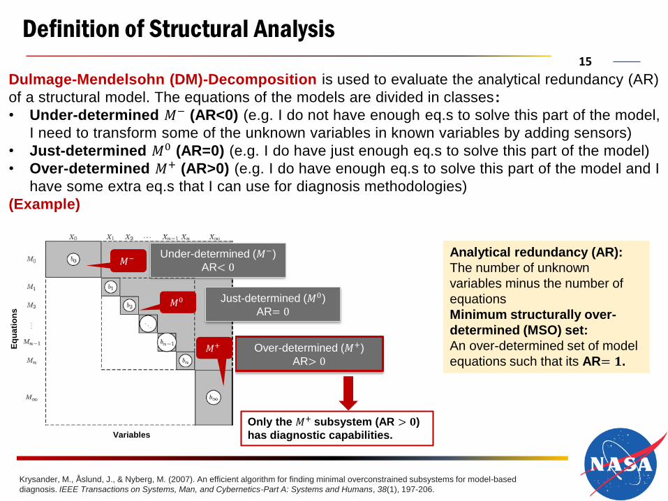
Definition of Structural Analysis
Analytical redundancy (AR):
The number of unknown
variables minus the number of
equations
Minimum structurally over-
determined (MSO) set:
An over-determined set of model
equations such that its AR= 𝟏.
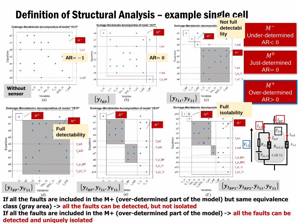
Dulmage-Mendelsohn (DM)-Decomposition is used to evaluate the analytical redundancy (AR)
of a structural model. The equations of the models are divided in classes:
• Under-determined 𝑀− (AR<0) (e.g. I do not have enough eq.s to solve this part of the model,
I need to transform some of the unknown variables in known variables by adding sensors)
• Just-determined 𝑀0 (AR=0) (e.g. I do have just enough eq.s to solve this part of the model)
• Over-determined 𝑀+ (AR>0) (e.g. I do have enough eq.s to solve this part of the model and I
have some extra eq.s that I can use for diagnosis methodologies)
(Example)
Only the 𝑀+ subsystem (AR > 𝟎)
has diagnostic capabilities.
Over-determined (𝑀+)
AR> 0
Variables
Eq
ua
tio
ns
𝑀−
𝑀0
𝑀+
Under-determined (𝑀−)
AR< 0
Just-determined (𝑀0)
AR= 0
Krysander, M., Åslund, J., & Nyberg, M. (2007). An efficient algorithm for finding minimal overconstrained subsystems for model-based
diagnosis. IEEE Transactions on Systems, Man, and Cybernetics-Part A: Systems and Humans, 38(1), 197-206.
16
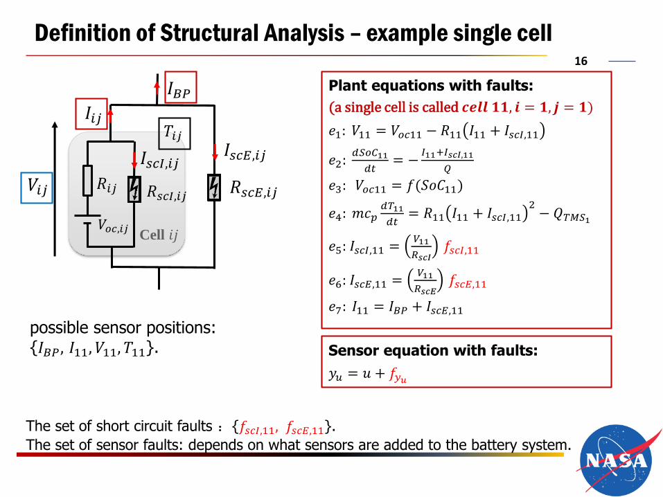
Definition of Structural Analysis – example single cell
Plant equations with faults:
(a single cell is called 𝒄𝒆𝒍𝒍 𝟏𝟏, 𝒊 = 𝟏, 𝒋 = 𝟏)
𝑒1: 𝑉11 = 𝑉𝑜𝑐11 − 𝑅11 𝐼11 + 𝐼𝑠𝑐𝐼,11
𝑒2:𝑑𝑆𝑜𝐶11
𝑑𝑡= −
𝐼11+𝐼𝑠𝑐𝐼,11
𝑄
𝑒3: 𝑉𝑜𝑐11 = 𝑓(𝑆𝑜𝐶11)
𝑒4: 𝑚𝑐𝑝𝑑𝑇11
𝑑𝑡= 𝑅11 𝐼11 + 𝐼𝑠𝑐𝐼,11
2− 𝑄𝑇𝑀𝑆1
𝑒5: 𝐼𝑠𝑐𝐼,11 =𝑉11
𝑅𝑠𝑐𝐼𝑓𝑠𝑐𝐼,11
𝑒6: 𝐼𝑠𝑐𝐸,11 =𝑉11
𝑅𝑠𝑐𝐸𝑓𝑠𝑐𝐸,11
𝑒7: 𝐼11 = 𝐼𝐵𝑃 + 𝐼𝑠𝑐𝐸,11
The set of short circuit faults :{𝑓𝑠𝑐𝐼,11, 𝑓𝑠𝑐𝐸,11}.
The set of sensor faults: depends on what sensors are added to the battery system.
possible sensor positions:{𝐼𝐵𝑃, 𝐼11, 𝑉11, 𝑇11}.
Cell 𝑖𝑗
𝐼𝑠𝑐𝐸,𝑖𝑗
𝑅𝑠𝑐𝐸,𝑖𝑗
𝐼𝐵𝑃
𝐼𝑠𝑐𝐼,𝑖𝑗
𝑉𝑜𝑐,𝑖𝑗
𝑅𝑠𝑐𝐼,𝑖𝑗
𝐼𝑖𝑗
𝑉𝑖𝑗 𝑅𝑖𝑗
𝑇𝑖𝑗
Sensor equation with faults:
𝑦𝑢 = 𝑢 + 𝑓𝑦𝑢
17
Definition of Structural Analysis – example single cell
If all the faults are included in the M+ (over-determined part of the model) but same equivalence class (gray area) -> all the faults can be detected, but not isolatedIf all the faults are included in the M+ (over-determined part of the model) -> all the faults can be detected and uniquely isolated
Withoutsensor
𝒚𝑰𝑩𝑷𝒚𝑰𝟏𝟏 , 𝒚𝑽𝟏𝟏
𝒚𝑰𝑩𝑷 , 𝒚𝑽𝟏𝟏 𝒚𝑰𝑩𝑷 , 𝒚𝑰𝟏𝟏 , 𝒚𝑽𝟏𝟏𝒚𝑰𝑩𝑷𝟏 , 𝒚𝑰𝑩𝑷𝟐 , 𝒚𝑰𝟏𝟏 , 𝒚𝑽𝟏𝟏
𝑀+
Over-determined
AR> 0
𝑀−
Under-determined
AR< 0
𝑀0
Just-determined
AR= 0
Cell 11
𝐼𝑠𝑐𝐸
𝑅𝑠𝑐𝐸
𝐼𝐵𝑃
𝐼𝑠𝑐𝐼
𝑉𝑜𝑐,11
𝑅𝑠𝑐𝐼,𝑖𝑗
𝐼11
𝑉11 𝑅11
𝑇11
AR= −𝟏 AR= 𝟎
Not full
detectabi
lity
Full
detectability
Full
isolability

18
Definition of Structural Analysis – example single cell
Cell 11
𝐼𝑠𝑐𝐸
𝑅𝑠𝑐𝐸
𝐼𝐵𝑃
𝐼𝑠𝑐𝐼
𝑉𝑜𝑐,11
𝑅𝑠𝑐𝐼,𝑖𝑗
𝐼11
𝑉11 𝑅11
𝑇11
(a) (b)
(c)
(d) (e) (f)
Not detectableNot detectable Not detectable
Detectable, not isolable
Detectable, not isolable Detectable, not uniquely isolable
Uniquely isolable
Uniquely isolable
Withoutsensor 𝒚𝑰𝑩𝑷 𝒚𝑰𝟏𝟏 , 𝒚𝑽𝟏𝟏
𝒚𝑰𝑩𝑷 , 𝒚𝑽𝟏𝟏 𝒚𝑰𝑩𝑷 , 𝒚𝑰𝟏𝟏 , 𝒚𝑽𝟏𝟏 𝒚𝑰𝑩𝑷𝟏 , 𝒚𝑰𝑩𝑷𝟐 , 𝒚𝑰𝟏𝟏 , 𝒚𝑽𝟏𝟏If all the faults are included in the M+ (over-determined part of the model) but same equivalence class (gray area) -> all the faults can be detected, but not isolatedIf all the faults are included in the M+ (over-determined part of the model) -> all the faults can be detected and uniquely isolated

19
ANALYSIS OF TRADITIONAL SENSOR SET
20
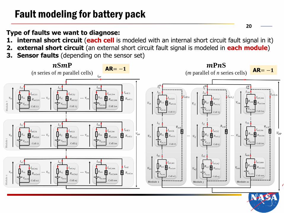
Fault modeling for battery pack
Type of faults we want to diagnose:1. internal short circuit (each cell is modeled with an internal short circuit fault signal in it)2. external short circuit (an external short circuit fault signal is modeled in each module)3. Sensor faults (depending on the sensor set)
𝒏S𝒎P(n series of m parallel cells)
𝒎P𝒏S(m parallel of n series cells)
AR= −𝟏 AR= −𝟏

21
Can a traditional sensor set diagnose/isolate internal and external short circuit faults as well as sensors (BMS) faults?
Traditional sensor set for the 𝒏S𝒎P topology battery pack: • a load current sensor to measure 𝐼𝐵𝑃 .
• cells that are in parallel share a voltage sensor (each module has a voltage sensor).• cells that are in parallel share a temperature sensor (each module has a temperature
sensor)
Module
1M
odule
𝐼𝐵𝑃
𝑉𝐵𝑃
Module
11 ⋯ ⋯1𝑗 1𝑚
𝑖1 ⋯ ⋯𝑖𝑗 i𝑚
𝑛1 ⋯ ⋯n𝑗 𝑛𝑚
𝐼1𝑀
𝐼𝑖𝑀
𝐼𝑛𝑀
𝑉1𝑀
𝑉𝑖𝑀
𝑉𝑛𝑀
𝑇1𝑀
𝑇𝑖𝑀
𝑇𝑛𝑀
Fault isolability matrix of 3S3P topology battery pack with
traditional sensor set 𝑦𝐼𝐵𝑃 , 𝑦𝑉𝑀1, 𝑦𝑉𝑀2
, 𝑦𝑉𝑀3, 𝑦𝑇𝑀1
, 𝑦𝑇𝑀2, 𝑦𝑇𝑀3
𝒏S𝒎P
Series of parallel cells
Mo
du
le 1
Mo
du
le 2
Mo
du
le 3
Current sensor
Voltage sensor
Temperature sensor
E.g. 𝟑S𝟑P
Cheng, Y., D’arpino, M., & Rizzoni, G. (2020). Structural Analysis for Fault Diagnosis and Sensor Placement in Battery Packs. IEEE Transactions
on Systems, Man, and Cybernetics-Part A: Systems and Humans, in preparation.

22
Can a traditional sensor set diagnose/isolate internal and external short circuit faults as well as sensors (BMS) faults?
Cheng, Y., D’arpino, M., & Rizzoni, G. (2020). Structural Analysis for Fault Diagnosis and Sensor Placement in Battery Packs. IEEE Transactions
on Systems, Man, and Cybernetics-Part A: Systems and Humans, in preparation.
Traditional sensor set for the 𝒎P𝒏S topology:• a load current sensor to measure 𝐼𝐵𝑃.
• each cell has its own voltage sensor.• cells that are in series share a single temperature sensor (each module has a temperature
sensor)𝐼𝐵𝑃
Module 1
𝑉𝐵𝑃
11
⋮
𝑖1
𝑛1
⋮
𝐼1𝑀
𝑉1𝑀
Module 𝑗
1j
⋮
𝑖𝑗
𝑛j
⋮
𝐼𝑗𝑀
𝑉𝑗𝑀
Module 𝑚
1𝑚
⋮
𝑖𝑚
𝑛𝑚
⋮
𝐼𝑚𝑀
𝑉𝑚𝑀
𝑇1𝑀 𝑇2
𝑀𝑇3𝑀
Fault isolability matrix of 3P3S topology battery pack with
traditional sensor set 𝑦𝐼𝐵𝑃 , 𝑦𝑇𝑀1
, 𝑦𝑇𝑀2, 𝑦𝑇𝑀3
, 𝑦𝑉11 , 𝑦𝑉21 , 𝑦𝑉31 ,𝑦𝑉12 , 𝑦𝑉22 , 𝑦𝑉32 , 𝑦𝑉13 , 𝑦𝑉23 , 𝑦𝑉33
𝒎P𝒏S
Parallel of series connected cells
Current sensor
Voltage sensor
Temperature sensor
Mo
du
le 1
Mo
du
le 2
Mo
du
le 3
E.g. 𝟑P𝟑S
23
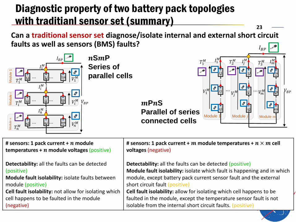
Diagnostic property of two battery pack topologies with traditianl sensor set (summary)
Can a traditional sensor set diagnose/isolate internal and external short circuit faults as well as sensors (BMS) faults?
Module
1M
odule
𝐼𝐵𝑃
𝑉𝐵𝑃
Module
11 ⋯ ⋯1𝑗 1𝑚
𝑖1 ⋯ ⋯𝑖𝑗 i𝑚
𝑛1 ⋯ ⋯n𝑗 𝑛𝑚
𝐼1𝑀
𝐼𝑖𝑀
𝐼𝑛𝑀
𝑉1𝑀
𝑉𝑖𝑀
𝑉𝑛𝑀
𝑇1𝑀
𝑇𝑖𝑀
𝑇𝑛𝑀
𝐼𝐵𝑃
Module 1
𝑉𝐵𝑃
11
⋮
𝑖1
𝑛1
⋮
𝐼1𝑀
𝑉1𝑀
Module 𝑗
1j
⋮
𝑖𝑗
𝑛j
⋮
𝐼𝑗𝑀
𝑉𝑗𝑀
Module 𝑚
1𝑚
⋮
𝑖𝑚
𝑛𝑚
⋮
𝐼𝑚𝑀
𝑉𝑚𝑀
𝑇1𝑀 𝑇2
𝑀𝑇3𝑀
# sensors: 1 pack current + 𝒏 module temperatures + 𝒏 module voltages (positive)
Detectability: all the faults can be detected (positive)Module fault isolability: isolate faults between module (positive)Cell fault isolability: not allow for isolating which cell happens to be faulted in the module (negative)
# sensors: 1 pack current + 𝒎 module temperatures + 𝒏 ×𝒎 cellvoltages (negative)
Detectability: all the faults can be detected (positive)Module fault isolability: isolate which fault is happening and in which module, except battery pack current sensor fault and the external short circuit fault (positive)Cell fault isolability: allow for isolating which cell happens to be faulted in the module, except the temperature sensor fault is not isolable from the internal short circuit faults. (positive)
𝒏S𝒎P
Series of
parallel cells
𝒎P𝒏S
Parallel of series
connected cells

24
PERFORMING SENSOR PLACEMENT TO FIND MINIMAL SENSOR SET THAT CAN ACHIEVE
COMPLETE FAULT ISOLATION
25
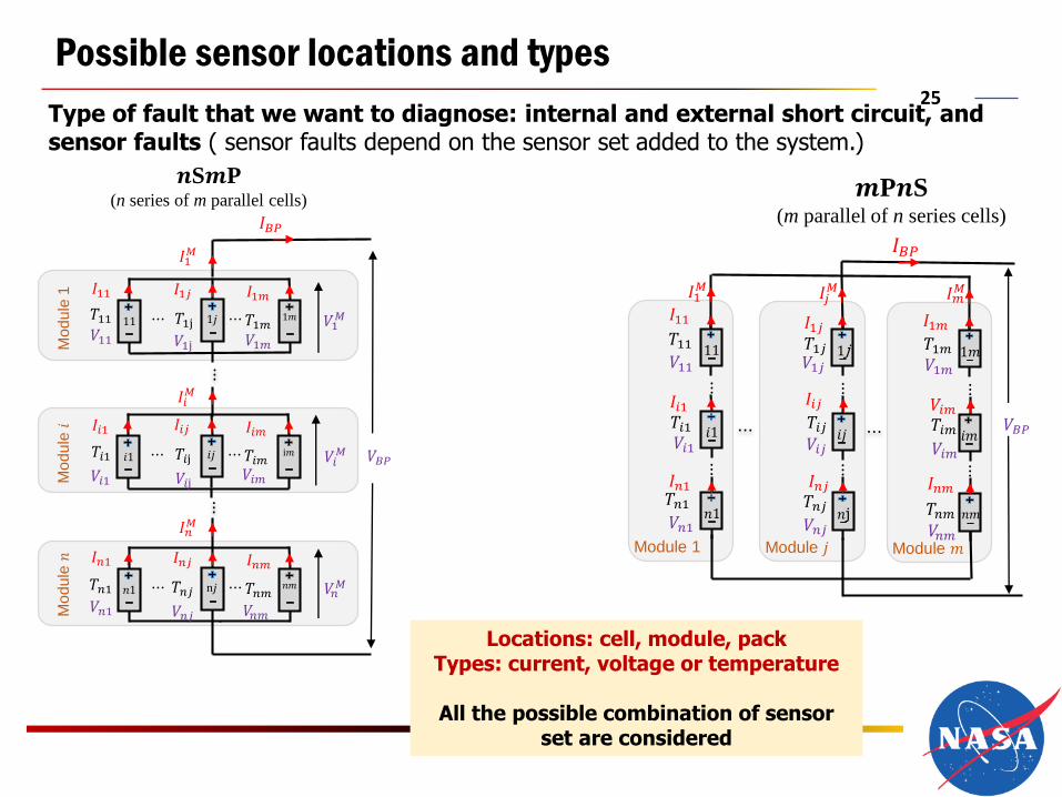
Possible sensor locations and types
Type of fault that we want to diagnose: internal and external short circuit, and sensor faults ( sensor faults depend on the sensor set added to the system.)
𝒏S𝒎P(n series of m parallel cells)
𝒎P𝒏S(m parallel of n series cells)
Locations: cell, module, packTypes: current, voltage or temperature
All the possible combination of sensor set are considered
Mo
du
le 1
Mo
du
le
𝐼𝐵𝑃
𝑉𝐵𝑃
Mo
du
le
𝑇11 11 ⋯ ⋯𝑇1j
𝐼1𝑗𝐼11 𝐼1𝑚
𝑇1𝑚1𝑗 1𝑚
𝑇𝑖1 𝑖1 ⋯ ⋯𝑇𝑖j
𝐼𝑖𝑗𝐼𝑖1 𝐼𝑖𝑚
𝑇𝑖𝑚𝑖𝑗 i𝑚
𝑇𝑛1 𝑛1 ⋯ ⋯𝑇𝑛𝑗
𝐼𝑛𝑗𝐼𝑛1 𝐼𝑛𝑚
𝑇𝑛𝑚n𝑗 𝑛𝑚
𝐼1𝑀
𝐼𝑖𝑀
𝐼𝑛𝑀
𝑉1𝑀
𝑉𝑖𝑀
𝑉𝑛𝑀
𝑉11 𝑉1j 𝑉1𝑚
𝑉𝑖1 𝑉𝑖j 𝑉𝑖𝑚
𝑉𝑛1 𝑉𝑛𝑗 𝑉𝑛𝑚
𝐼𝐵𝑃
Module 1
𝑉𝐵𝑃
𝑉1111
𝑇11
⋮
𝑉𝑖1𝑖1
𝑉𝑛1𝑛1
⋮
𝑇𝑖1
𝑇𝑛1
𝐼1𝑀
Module 𝑗
𝑉1𝑗1j𝑇1𝑗
⋮
𝑉𝑖𝑗𝑖𝑗
𝑉𝑛𝑗𝑛j
⋮
𝑇𝑖𝑗
𝑇𝑛𝑗
𝐼𝑗𝑀
Module 𝑚
𝑉1𝑚1𝑚𝑇1𝑚
⋮
𝑉𝑖𝑚𝑖𝑚
𝑉𝑛𝑚𝑛𝑚
⋮
𝑇𝑖𝑚
𝑇𝑛𝑚
𝐼𝑚𝑀
𝐼11 𝐼1𝑗 𝐼1𝑚
𝐼𝑖1 𝐼𝑖𝑗 𝑉𝑖𝑚
𝐼𝑛1 𝐼𝑛𝑗 𝐼𝑛𝑚
26
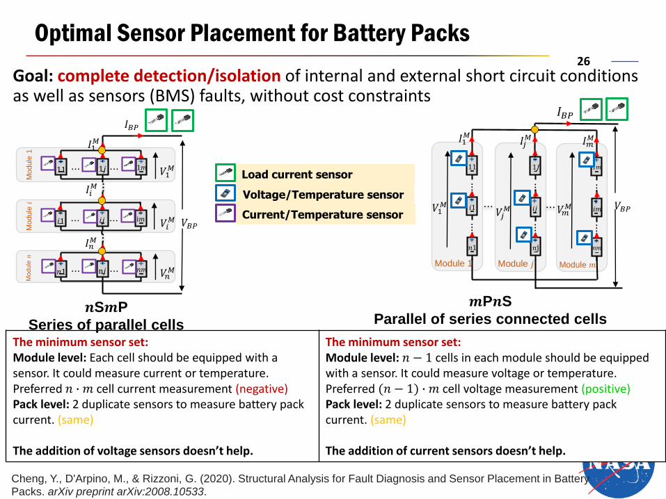
Optimal Sensor Placement for Battery Packs
Goal: complete detection/isolation of internal and external short circuit conditions as well as sensors (BMS) faults, without cost constraints
𝐼𝐵𝑃
Module 1
𝑉𝐵𝑃
11
⋮
𝑖1
𝑛1
⋮
𝐼1𝑀
𝑉1𝑀
Module 𝑗
1j
⋮
𝑖𝑗
𝑛j
⋮
𝐼𝑗𝑀
𝑉𝑗𝑀
Module 𝑚
1𝑚
⋮
𝑖𝑚
𝑛𝑚
⋮
𝐼𝑚𝑀
𝑉𝑚𝑀
Module
1M
odule
𝐼𝐵𝑃
𝑉𝐵𝑃
Module
11 ⋯ ⋯1𝑗 1𝑚
𝑖1 ⋯ ⋯𝑖𝑗 i𝑚
𝑛1 ⋯ ⋯n𝑗 𝑛𝑚
𝐼1𝑀
𝐼𝑖𝑀
𝐼𝑛𝑀
𝑉1𝑀
𝑉𝑖𝑀
𝑉𝑛𝑀
The minimum sensor set: Module level: Each cell should be equipped with a sensor. It could measure current or temperature. Preferred 𝑛 ∙ 𝑚 cell current measurement (negative)Pack level: 2 duplicate sensors to measure battery pack current. (same)
The addition of voltage sensors doesn’t help.
The minimum sensor set: Module level: 𝑛 − 1 cells in each module should be equipped with a sensor. It could measure voltage or temperature. Preferred (𝑛 − 1) ∙ 𝑚 cell voltage measurement (positive)Pack level: 2 duplicate sensors to measure battery pack current. (same)
The addition of current sensors doesn’t help.
𝒏S𝒎P
Series of parallel cells
𝒎P𝒏S
Parallel of series connected cells
Load current sensor
Voltage/Temperature sensor
Current/Temperature sensor
Cheng, Y., D'Arpino, M., & Rizzoni, G. (2020). Structural Analysis for Fault Diagnosis and Sensor Placement in Battery Packs. arXiv preprint arXiv:2008.10533.

27
Conclusions
• A comparative analysis between SP and PS has been carried out• PS seems to have several advantages due to the fact that the entity of the fault or imbalance in
case of malfunction is 𝑛 times smaller than SP, however the malfunction is spread across the whole pack
• A methodology for the optimal sensor set has been proposed and compared with traditional sensor set. The team is performing further economic analysis.
Load current sensorC
Voltage sensor and hardware for
voltage balancingV
Cell current sensorC
T Temperature sensor
Optimal set up for battery packHaving fully fault detection and isolation (FDI) capability
Traditional set up for battery packsHaving partial fault detection and isolation (FDI) capability
𝒎P𝒏S
(b) 𝒎P𝒏S with traditional sensor set
𝐼𝐵𝑃
Module 1
𝑉𝐵𝑃
11
⋮
𝑖1
𝑛1
⋮
𝐼1𝑀
𝑉1𝑀
Module 𝑗
1j
⋮
𝑖𝑗
𝑛j
⋮
𝐼𝑗𝑀
𝑉𝑗𝑀
Module 𝑚
1𝑚
⋮
𝑖𝑚
𝑛𝑚
⋮
𝐼𝑚𝑀
𝑉𝑚𝑀
V
C
V
V
V
V
V
V
V
V
T T T
𝐼𝐵𝑃
Module 1
𝑉𝐵𝑃
11
⋮
𝑖1
𝑛1
⋮
𝐼1𝑀
𝑉1𝑀
Module 𝑗
1j
⋮
𝑖𝑗
𝑛j
⋮
𝐼𝑗𝑀
𝑉𝑗𝑀
Module 𝑚
1𝑚
⋮
𝑖𝑚
𝑛𝑚
⋮
𝐼𝑚𝑀
𝑉𝑚𝑀
V
C
V
V
V
V
V
V
V
V
C
(d) 𝒎P𝒏S with optimal sensor set
𝒏S𝒎P
Module
1
Module
𝐼𝐵𝑃
𝑉𝐵𝑃
Module
11 ⋯ ⋯1𝑗 1𝑚
𝑖1 ⋯ ⋯𝑖𝑗 i𝑚
𝑛1 ⋯ ⋯n𝑗 𝑛𝑚
𝐼1𝑀
𝐼𝑖𝑀
𝐼𝑛𝑀
𝑉1𝑀
𝑉𝑖𝑀
𝑉𝑛𝑀
C
V
V
V
T
T
T
Module
1
Module
𝐼𝐵𝑃
𝑉𝐵𝑃
Module
11 ⋯ ⋯1𝑗 1𝑚
𝑖1 ⋯ ⋯𝑖𝑗 i𝑚
𝑛1 ⋯ ⋯n𝑗 𝑛𝑚
𝐼1𝑀
𝐼𝑖𝑀
𝐼𝑛𝑀
𝑉1𝑀
𝑉𝑖𝑀
𝑉𝑛𝑀
C
VC C C
C C C
C C C
V
V
C
(c) 𝒏S𝒎P with optimal sensor set
(a) 𝒏S𝒎P with traditional sensor set

©, The Ohio State University, 2019
CONTACTcar.osu.edu
Prof. Giorgio Rizzoni ([email protected]) Ye Cheng ([email protected])
Research Scientist
Dr. Matilde D’Arpino
Thank You for Your Kind Attention!
The authors thank the NASA ULI programfor sponsoring this research (GRANTnumber NNX17AJ92A).


