
42A14SEe328 2 .2766 REID 010
!";-k 'i'" l M Li
LAND3 SU
DETAILED GEOPHYSICAL COVERAGE
TULLY TOWNSHIP "B" BLOCK
TIMMINS AREA NORTHEASTERN ONTARIO
for
NORCEN ENERGY LTD.
Toronto, Ontario, Canada February, 1979
W. E. Brereton, M.Se.(A) M P H CONSULTING LIMITED

INTRODUCTION AND SUMMARY
Additional linecutting and geophysical surveys (MaxMin
II electromagnetic and magnetometer) were carried out
over the Tully "B" Block in June/ 1978. This work is
supplemental to previous surveys carried out in early
1978 which are described in a report entitled "Report
on Electromagnetic and Magnetic Surveys on Claim Groups
in MacDiarmid, Reid/ Murphy and Tully Townships/ Timmins
Area, Porcupine Mining Division" by W. E. Brereton/
dated May, 1978.
The latest surveys more accurately defined and extended
conductive zones "2" and "3" located by the previous geo
physical work.

l
lm
lliisl
LOCATION AND ACCESS
The six claims straddle the Buskegau River in the
northeast quarter of the township.
.
(Easiest access is by helicopter from Timmins.

iGEOPHYSICAL SURVEYS
The surveys were carried out on cut and picketed line
grids. North-south crosslines were established at
100 metre intervals for a total of 7 km of line.
Magnetic data were recorded with a Scintrex MP - 2 pro
ton magnetometer at 25m intervals. Base stations were
established as required and the data were corrected
for duirnal magnetic variation.
A MaxMin II EM unit was used for the EM surveying at
frequencies of 444 Hz and 1777 Hz and coil separation
of 600 ft.
Technical details of the methods and instruments are
presented in Appendix I of the parent report.

GEOPHYSICAL RESULTS
Electromagnetic
Nine MaxMin conductors, EM1 to EM9/ have been interpreted based
on the results of the present and previous work.
Conductors EM1 to EMS appear to represent narrow, discreet fea
tures within a complex, steeply-dipping zone of multiple conduc
tors {previous conductive zone 2). Conductivity thickness pro
ducts decrease markedly from 1777 Hz to 444 Hz indicating a
source other than massive conductive sulphides. Previous dia
mond drill hole 65-1 by Utica Mines Ltd. in 1965 appears to have
intersected EMS. The hole cut a 7.9 m (26 ft) core length con
taining nodular pyrite in rhyodacite breccia in the area of the
present conductor. Overburden depth is 27m (90 ft).
Conductors EM4 and EMS are also weak, poorly conductive, steeply-
dipping features. These may be the eastward continuation of
EM2 and EMS across a north-south fault postulated to occur be
tween lines IE and 2E (EM9). Conductors EM6, EM7 and EM8 are
part of a weakly conductive, steeply-dipping line of multiple
conductors. Two holes by Consolidated Novell Mines in 1965
failed to intersect EMS. Overburden thickness is 65m (215 ft).
A previous interpretation of a northwest-southeast conductive
fault zone (Zone "l")in this region does not appear to be
valid.

lMagnetic
A pronounced magnetic high centred at IS on line 4W represents
the east end of an ultrabasic intrusive intersected to the west
l by diamond drilling. The intrusion appears to be truncated to
the east between lines 3W and 4W by a north-striking fault.
l* Apparent displacement of EM6, the westward continuation of EM7 ,
B indicated a right lateral movement on the order of 50m. EM6
occurs immediately north of the above ultrabasic.
lA magnetic high at the south end of line 1W probably represents
'lm another basic-ultrabasic body.
lOverall magnetic trends are east-west.
lThere is no direct magnetic correlation with any of the conduc-
l
l
l
l
l
l
l
l
tors.

CONCLUSIONS
Additional magnetic and MaxMin II Em surveys on the Tully "B"
Block have served to more accurately define previously located
anomalies. Nine EM conductors were outlined.
Consideration should be given to re-testing conductors EM2 and/
or EMS in that the previous drilling intersected semi-massive
sulphides in felsic volcanic rocks in the immediate area of the
conductors.
EM6 is also a potential drill target for gold possibilities
as is the east end of conductors EM7 and EMS.
l
il Respectfully submitted,
, WEBrg W. E. Brereton, M.Se.(A)
l
l
l
J

CERTIFICATE OF QUALIFICATIONS
I, William E. Brereton of 330 Ontario St., Toronto, Ontario do
hereby certify that:
1) I was granted a Bachelor of Science degree with Honours from
Queen's University/ Kingston, Ontario in Geology and Physics
(1971) and a Master of Science degree (Applied) from McGill
University, Montreal, Quebec in Mineral Exploration (1977).
2) I have been practising my profession in mining since gradua
tion. Conclusions and recommendations contained in this re
port are based on a knowledge of the geology and base metals
potential of and geophysical applications within the Abitibi
gained through several years' experience in the area.
Dated at Toronto, Ontario this 2nd day of March, 1979.
lW. E. Brereton
l
i
i
ii

VOLUME I
42AHSEe328 2.2708 REID OSO
JUN l 19/8
MINING UNDS SECT/ON
REPORT ON ELECTROMAGNETIC AND MAGNETIC SURVEYS
ON CLAIM GROUPS IN
MACDIARMID, REID, MURPHY AND TULLY TOWNSHIPS
TIMMINS AREA
PORCUPINE MINING DIVISION
for
GREAT PLAINS DEVELOPMENT COMPANY OF CANADA LTD,
Toronto, Ontario, Canada May, 1978
W. E. Brereton, M.Se.(A) M P H CONSULTING LIMITED

SUMMARY
Geophysical surveys {MaxMin II, magnetometer) on 5 claim
blocks totalling 44 claims north of Timmins, Ontario have
located a total of 8 conductors as follows:
Claim Block
Conductive Zone
Conductivity (inphase/ quadrature)
Conductivity- Thickness
(mhos)Comments
Reid"A"
Murphy"A" l
Low
Low
Shear and/or graphi tic tuff
3 Shear (line 8S)
Murphy"A" 2 moderate to very good to 35(444Hz At least one 120mline 3E) drill hole
Tully"A"
Tully"A"
Tully"B"
Tully"B"
Tully"B"
1
2
1
2
3
Low
Low
Low
Good (?)
Moderate
5 Shear and/or graphi tic tuff
4 Potential drill tar get
4(444Hz) Buskegau River Fault
Possibly drilled by previous workers
3 Potential drill tar get
Zone 2 on the Tully "A" block and Zone 3 on the Tully "B"
block require additional geophysical definition before dril
ling. Zone 2 on the Tully "B" block is a potential drill
target until it can be positively established whether or
not this conductor was drilled by previous workers in 1965.

iii i l . mgm
9
INTRODUCTION
During the period January 15 to April 10, 1978, magnetic and electromagnetic surveys were carried out over five properties north of Timmins, Ontario, for Great Plains Development Com pany of Canada Ltd. Field operations were carried out by Geoex Limited of Timmins under contract to M P H Consulting Limited of Toronto who were responsible for overall programme supervision, data interpretation and report preparation.
The five properties are as follows:
1) Macdiarmid Township - "A" Block
Claims P 452357 to P 452374 inclusive andClaims P 495317 to P 495322 inclusive (Total - 24 claims)2) Reid Township - "A" Block
Claims P 495323 to P 495326 inclusive (Total - 6 claims)3) Murphy Township - "A" Block
Claims P 452382 to P 452385 inclusivebeing the S 1/2 of Lot 6, Concession 3(Total - 4 claims)
4) Tully Township - "A" Block
Claims P 500514 to P 500519 inclusivebeing the N 1/2 of Lot 3, Concession 6and the NW 1/4 and SW 1/4 of the N 1/2of Lot 2, Concession 6 (Total - 6 claims)
5) Tully Township - "B" Block
Claims P 500520, P 500521 and P 500334 to P 500337 inclusive being the N 1/2 of Lot 5, Concession 4 and the NW 1/4 and SW 1/4 of the N 1/2 of Lot 4, Con cession 4 (Total '
TOTAL CLAIMS
6 claims) 44 claims

l
lfi!
iE 1
l
i i i i
The claims are located in the west central portion of the
Abitibi greenstone belt within a 25 mile radius north of the
city of Timmins (Location Map - pocket l at rear).

GEOPHYSICAL SURVEYS
a) Grids
All surveys were carried out on cut and picketed line
grids. Line spacing was 100m in all cases with the
exception of the Tully "B" block where crosslines were
inadvertently cut at a 125m spacing.
A total of 87.5 km of line was cut and chained with sta
tions at 25 m intervals. Two grids at right angles were
required to adequately investigate the Murphy claims.
b) Methods
Magnetic data were systematically recorded with a Scin-
trex MP-2 proton (total field) magnetometer at 25m inter
vals. Base stations were established as required and the
data were corrected for duirnal magnetic variations.
A MaxMin II electromagnetometer was used for the EM sur
veying. The horizontal loop {maximum coupled) mode was
employed throughout. A coil separation of 600 ft. (183m)
and frequencies of 444 Hz and 1777 Hz were used for rou
tine coverage.
Technical details of the methods and instruments are
presented in Appendix I.

c) Presentation of Results
The geophysical results accompany this report under se
parate cover.
The magnetic data are presented as contoured plans at a
scale of 1:2500 with a 25 gamma contour interval.
The EM data are presented in profile form at a profile
scale of l cm to 101; and a map scale of 1:2500.

DISCUSSION OF PROPERTIES
The five properties are discussed following as to location
and access, previous work, geology and geophysical results.
1) Macdiarmid Township - "A" Block
a) Location and Access - The Macdiarmid claims are lo
cated in the northeast part of the township, one
claim west of the powerline which leads south from
the Sturgeon Falls dam on the Mattagami River. The
road along the powerline was kept open by Ontario
Hydro last winter, which/ in conjunction with some
logging roads, allowed easy truck access to the pro
perty.
b) Previous Work - The most significant previous work
consists of a 1964 diamond drill programme by Silver
Men Mines Limited immediately east of the central
portion of the east claim boundary. One hole (no.11)
intersected a 125 ft. section of up to 5Q* pyrite
and pyrrhotite in brecciated rhyolite and graphitic
fragmental tuff. Sphalerite and chalcopyrite are
reported within one of the graphitic sections in the
sulphide zone. Other drilling in the immediate area
(drill hole nos. 6,7,8,9,12,13) showed bedrock to
consist of andesitic volcanics and tuffs containing

l
units of massive to brecciated rhyolite. The drill
results indicate that there are two sulphide-gra
phite zones separated by approximately 500 ft. which
strike west and northwest onto the Great Plains'
ground.
l Previous and subsequent ground electromagnetic sur
veys by Consolidated Regcourt Mines (1964) and
l Belleterre Quebec Mines (1965-66) defined numerous
weak conductors in the area covered by the present
l claims. There are 2 Turair anomalies and 2 INPUT
M (Mark 5) anomalies on the ground as a result of 1970-
71 surveys by Mattagami Lake Mines and Hollinger
l Mines respectively.
l
l
c ) Geology - The data compilation map for Macdiarmid
Township (ODM map P.730) indicates the claims to be
underlain by a northwest-striking sequence of felsic
l and mafic to intermediate metavolcanics. There is
an outcrop of felsic metavolcanics in the central
l portion of claim P 495318. Our regional interpre-
M tation indicates that tops here are to the north.
m The Silver Men massive sulphide prospect is indica-
ted to be at a contact between underlying felsic
l metavolcanics to the south and mafics to the north.
This contact continues westward onto the Great
l

l
Plains' ground.
The Montreal River Fault crosses the extreme north
east corner of the claims.
d) Geophysical Results - There are conductive indica
tions in several areas on the property characterized
by high positive inphase and, particularly, high
positive quadrature readings flanked by narrow,
slightly negative wells. The effect is best display
ed at 1777 Hz along lines 7N and 8N in the area of
tie-line 10W and in the northeast corner of the pro
perty e.g. line 3N (maps IB, 1C). Profile shapes
and conductivity-thickness calculations obtained
from detail information on lines 7N, 8N and 12N at
all four available frequencies (222 Hz, 444 Hz, 888
Hz, 1777 Hz) indicate that these "anomalies" are
conductive overburden effects related to buried
bedrock highs (map ID). The "anomaly" along tie-
line 10W coincides in part with a north-south,
linear magnetic high interpreted as a diabase dyke
which probably forms the bedrock high.
Magnetic trends are north-south over most of the
property in contrast with the indicated west to north
west strikes of the underlying metavolcanics. This
effect is probably due to diabase intrusives. A

li l l
thick, north-striking dyle is inferred to cross the
west part of the property.
There is some indication of more east-west magnetic
trends in the northeast portion of the property.
The circular magnetic high in the southwest corner
of claim P 452364 appears to represent a small,
northeast-plunging, cylindrical body and may be a
basic plug.
The significance of the magnetic high in the extreme
northeast corner of the property (claim P 452357) can
not be determined as the anomaly extends off the exis ting ground.
Comments - No bona fide bedrock conductors have been loca ted to date.
Additional work may be warranted in an attempt to locate a continuation of the Silver Men zone onto the present claims.

10
I 2) Reid Township - "A" Block
l a ) Location and Access - The Reid claims are located
l
in the extreme northeast corner of the township.
The powerline road described for the Macdiarmid
claims passes along the west claim boundary.
b) Previous Work - There are several apparently untes
ted ground electromagnetic anomalies located in
1965-66 surveys by Terra Nova Explorations Ltd.on
the claims. Two holes by Phelps Dodge in 1975
about 3/4 miles northwest of the Great Plains'
block cut long graphitic sections (up to 156 ft),
with minor sulphides in mainly felsic flows and
pyroclastics. This geology is striking south on
to the present claims.
c) Geology - The four claims straddle about 1/2 mile
of a west-northwest striking fault contact between
felsic metavolcanics to the south and andesite-
basalt to the north according to the Reid compila
tion (Map P700).
A north-northwest magnetic trend over the west part
of the group (map 2A) is interpreted as a diabase
dyke which appears to be offset in a left lateral
fashion along a west-northwest fault. This fault
coincides with that postulated by the ODM geolo
gists.

11
There is no outcrop.
d) Geophysical Results - There are no EM or magnetic
anomalies of potential economic significance. The
major fault which cuts centrally across the claims
has a weak but definite EM expression (maps 2B,2C).
Calculated depths to conductor are on the order of
50m.
Alternatively there may be a weakly graphitic tuf
faceous unit along the felsic-mafic contact.
Comments - The Terra Nova horizontal loop anomalies are pro
bably due to conductive overburden effects. A Terra Nova
vertical loop anomaly on claim P 495324 probably reflects
the fault.
No further work is warranted at the present.
3) Murphy Township - "A" Block
a) Location and Access - The Murphy claims are loca
ted in the central part of the township less than
1/2 mile east of highway 655 which leads from
Timmins to Texasgulf's Kidd Creek Mine.
b) Previous Work - A vertical loop electromagnetic
survey by Volcanic Mines Limited in 1968 covered
the 4 Murphy claims as part of a larger programme

12
in the immediate area. Subsequent (1971) drilling
by Amax on one of the three vertical loop conduc
tors two claims west of the existing Great Plains'
ground showed a zone of massive pyrite-pyrrhotite
in felsic fragmentals.
In 1969, Amax also drilled a hole in the northeast
corner of present claim P 452382 to test an I P ano
maly.
c) Geology - The claims are probably underlain pre
dominantly by intermediate to felsic flows and pyro
clastics considering drilling on and to the west of
the ground.
There are outcrops of pillowed basalt less than
1/2 mile from the southwest corner of the group so
that part of the south claims may be underlain by
more basic volcanics.
A major north-northwest trending esker crosses the
two westerly claims. Coincident with this esker
is an increase in overburden depths as calculated
from the electromagnetic data and a disruption/
truncation of ground magnetic trends {maps 3A,3B,
3C). The esker is therefore interpreted to be oc
cupying a north-trending fault or fault zone, pos
sibly several hundred feet wide. The arcuate

l
iii
13
pattern and westward increasing nature of the mag
netic data reflects a serpentinite body centred
about l mile west.
Bedrock strikes on the property are probably east
to northeast with moderate dips.
There is no outcrop.
d) Geophysical Results - The EM results indicate two
conductive responses, Zones l and 2 (maps 3B, 3C).
Zone l is a vertically dipping, generally very nar
row, weak conductor and is interpreted as a north-
south fault zone now occupied by the esker.
This conductor is either distinct from or superim
posed on Zone 2. Considering just the EM response,
Zone 2 is interpreted as an arcuate body about 275m
long plunging about 45 degrees to the northeast.
Conductivity is moderate to very good being the
strongest on line 3E where the high frequency in-
phase to quadrature ratio is about 2.5 to l and the
low frequency conductivity-thickness product is
about 35 mhos. Depth to current axis is in the or
der of 30 m.
The magnetics provide a somewhat different interpre
tation. There is a very definite truncation of the

l
l
l
l*
l
14
magnetic contours coincident with the conductor
immediately west of line 3E suggesting that the
east-west portion of Zone 2 may not be related to
the north-south portion. The latter may be part
of Zone l, i.e. the fault.
There is a slight magnetic low associated with the
east-west portion of Zone 2 (40 gammas on line 3E.)
Comments - The strong conductor on line 3E should be drill
tested by a hole drilled grid south at -50O from 2 7* 70S
for approximately 120 m.
Serious consideration should also be given to investigat
ing the north-south portion of Zone 2 in a hole drilled
from the same set-up as previous at -50 on a bearing of
az 230 degrees for approximately 120m.
4' Tully Township - "A" Block
a) Location and Access - The claims are located in
the extreme northeast corner of the township and
are most easily accessible by helicopter from
Timmins.
b) Previous Work - Noranda Mines Limited (1968-69)
located 3, three-channel INPUT anomalies, one
with magnetic correlation/ over the present claim

15
block. Subsequent vertical loop follow-up located
5 conductors. There is no record of any drilling.
c) Geology - The six claims straddle about 3/4 mile
of the upper (?) contact between an approximately
one mile wide felsic unit to the south and inter
mediate-basic metavolcanics to the north (ODM map
P 699).
There is no outcrop on either of the Tully blocks.
d) Geophysical Results - Two conductive zones are pre
sent. Zone "l" trends southeast across the entire
grid except for an interruption in the area of
lines 8E, 9E and 10E. The conductor is very weak
and displays low conductivity being mainly a qua
drature effect at 444 Hz. A vertical to very steep
northeast dip is indicated. A calculation on the
444 Hz data on line 4E gave a depth to current
axis of approximately 60 meters and a conductivity-
thickness of 5 mhos. Conductor "l" coincides very
closely with the major felsic-mafic contact which
is shown to cross the claims on the Tully data com
pilation map. The situation is therefore identical
to that in Reid and Conductor "l" represents a
weakly graphitic tuffaceous or sedimentary horizon
and/or a zone of shearing coincident with the contact.

P l
l
l
16
Conductor "2" is a weak but definite, mainly quadra
ture feature at 444 Hz. The response is obscured by
noise at 1777 Hz. A relatively narrow, steeply dip
ping zone is indicated. Calculations on the low fre
quency data on line IDE give a depth to current axis
of approximately 45m and a conductivity-thickness of
4 mhos. Bedrock here is indicated to be basic vol
canics.
There is a positive buildup in both inphase and qua
drature at 1777 Hz and mainly in the quadrature at
444 Hz at the north ends of particularly lines 8E
and 9E. This is interpreted as an overburden effect
analagous to that in Macdiarmid.
There is no magnetic association with either conduc
tor.
Comments - There are no drill targets in Zone "l". Zone "2"
in the area of l -f 7 5N, line 10E is a potential drill target
but further definition is required. Lines HE and 12E should
be extended to the north. Lines 9E, 10E, HE and 12E should
then be re-surveyed with an 800 ft. (242m) cable using the
lower frequencies. Line 9E should be extended to the north
to make certain that the conductive indication here is an
overburden effect. Further recommendations will be contin
gent on the results of this work.

17
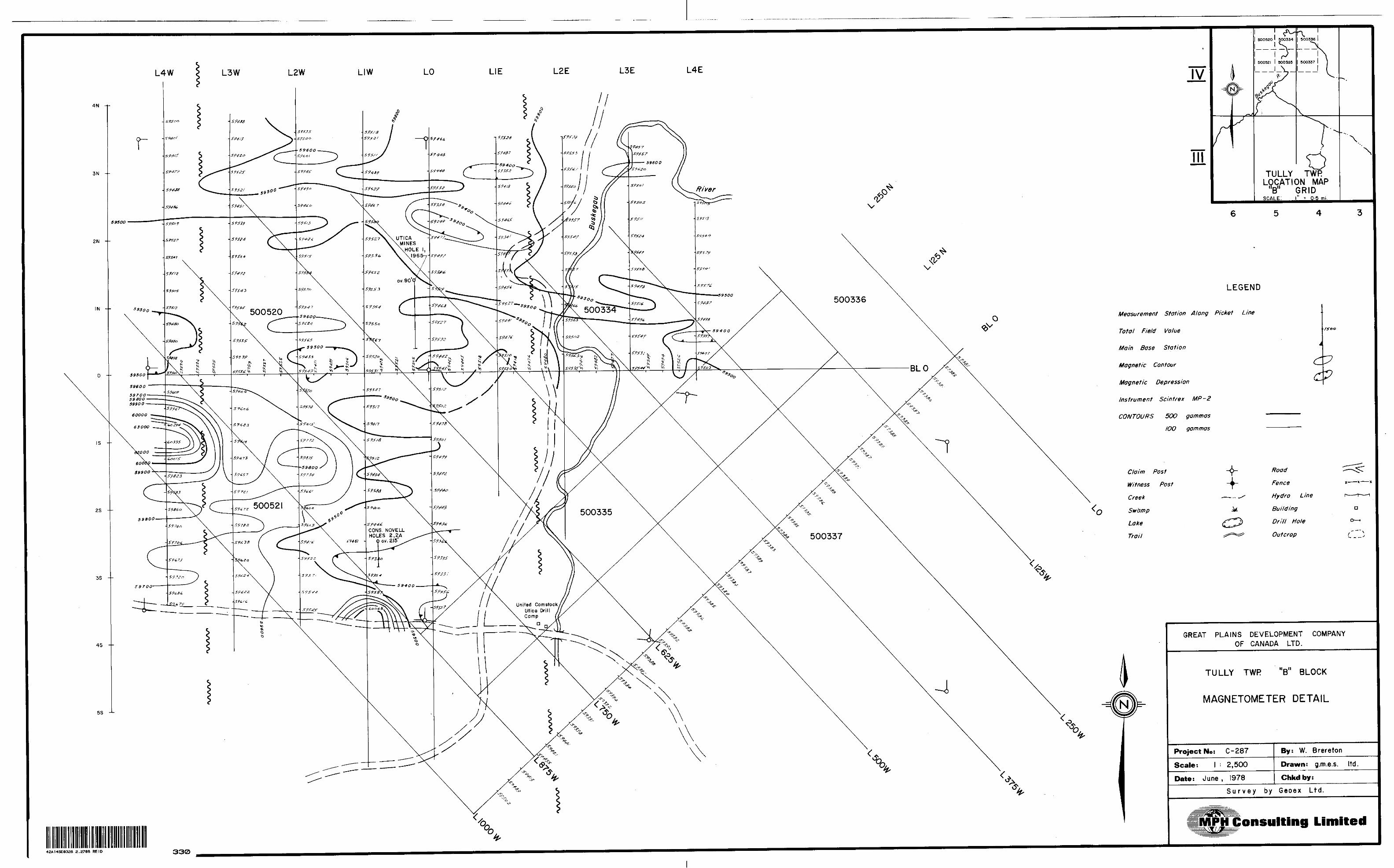
5) Tully Township - "B" Block
a) Location and Access - The six claims straddle the
Buskegau River in the northeast quarter of the
township. Easiest access is by helicopter from
Timmins.
b) Previous Work - In 1965, Utica Mines Limited dril
led a 489-ft. hole on an east-west striking hori-:
zontal loop anomaly in the northwest portion of the
present block (claim P 500520). The hole intersec
ted a 6 ft. section of 50% pyrite-pyrrhotite within
a sequence of rhyodacitic flows and pyroclastics
with minor tuff and greywacke. Minor chlorite-epi-
dote and graphite are mentioned. There are several
other conductors which were never tested.
Two holes by Consolidated Novell Mines Limited in
1965 on present claims P 500521 failed to reach
their intended target, a horizontal loop conductor,
due to drilling problems. The drilling showed bed
rock to consist of acid pyroclastics.
Texmount Mines defined a "very weak" vertical loop
anomaly in the north half of present claim P 500355
which was apparently never drill tested.
United Comstock Mines Ltd. in a 1965 drill hole on
an EM conductor immediately to the south of the

18
existing block intersected numerous graphitic
zones in a sequence of massive and brecciated rhyo-
lites.
c ) Geology - Interpretation of the magnetic and elec
tromagnetic data indicates that a north-northwest
trending fault (Buskegau River Fault) crosses the
east portion of the claims (maps 5A, 5B, 5C). East
of the fault, bedrock is indicated to consist of
east-west striking mafic and felsic metavolcanics
with an intercalated greywacke unit. The area west
of the fault is underlain mainly by felsic meta
volcanics. A magnetic high on lines 875W and
1000W reflects the east end of an ultrabasic body
l indicated on map P 699.
ld) Geophysical Results - There are 3 conductive zones.
Il Zone l occurs in the central part of the group, be
tween lines 3 J 7 5W and 5 J O OW and is interpreted
to consist of two narrow, steeply dipping conduc
tors with a depth to current axis of about 55m and
a conductivity-thickness of 20 mhos (east conductor,
1777 Hz). At 444 Hz, conductivity-thickness is 4
mhos. The conductive zone crosscuts local magnetic
trends at about right angles.
This zone is interpreted to represent the Buskegau

19
River Fault.
The grid lines over Zone "2" are at a low angle to
the conductor as reflected in the long positive
buildup to the conductor from the south. Also,
the positive shoulders are not completed on the
north side as the conductor occurs close to the
property boundary so that a meaningful interpreta
tion of depth etc. is not possible. There is an
indication, however, of good conductivity, i.e.
large inphase to quadrature ratio, at 1777 Hz on
line 5 J O OW.
The quadrature predominates at the lower frequency
and indicated conductivity decreases markedly at
444 Hz. This zone appears to be that drilled by
Utica Mines in 1965 (see Previous Work). The 6 ft.
section of 50S, pyrite-pyrrhotite in the hole would
not be inconsistent with the Zone 2 EM response.
Zone 3 appears to be the east end of the EM conduc
tor that Consolidated Novell Mines failed to inter
sect in two drill attempts in 1965. The 1777 Hz
data on line 1000W indicate a steeply south dipping
zone with a conductivity-thickness of 3 mhos. Depth
to current axis is interpreted at approximately 20m
in contrast with a known overburden thickness of 36m
in Consolidated Novell hole 2A somewhere to the west,

20
Zone 3 occurs on the east end of an elliptical mag
netic anomaly and is possibly associated with an
ultrabasic.
A broad, very weak quadrature anomaly which extends
east-west across the central portion of the proper
ty is interpreted as an overburden effect.
Comments - Zones 2 and 3 should be re-defined on 100m, north-
south lines as a prelude to possible diamond drilling. A
field check should be carried out in the area of Zone 2 in
an attempt to locate the old Utica drill hole.
Further recommendations will be contingent on the results of
the above.

21
CONCLUSIONS
Work to date on 5 claim blocks north of Timmins consist
ing of line-cutting, MaxMin II and magnetometer surveys
has outlined one definite drill target, namely Zone 2 on
the Murphy township "A" block.
Zone 2 on the Tully "A" block and Zones 2 and 3 on the
Tully "B" block are potential drill targets. Additional
geophysics and field checks are necessary before any firm
recommendations can be made.
lRespectfully submitted,
l
l
l
WEB:g W. E. Brereton, M.Se.(A)

il
l!"
l
22
CERTIFICATE OF QUALIFICATIONS
I, William E. Brereton of 23 Helmer Avenue, South Porcupine, Ontario do hereby certify that:
1) I was granted a Bachelor of Science degree with Honours from Queen's University, Kingston, Ontario in Geology and Physics (1971) and a Master of Science degree (Ap plied) from McGill University, Montreal, Quebec in Mineral Exploration (1977).
2) I have been practising my profession in mining since gra duation. Conclusions and recommendations contained in this report are based on a knowledge of the geology and base metals potential of and geophysical applications within the Abitibi gained through several years' exper ience in the area.
Dated at Toronto, Ontario this 10th day of May, 1978.
W. E. Brereton

23
APPENDIX l
SPECIFICATIONS

BRIEF DESCRIPTION OF THE MAXMIN II EM SYSTEM
The MaxMin II is a two-man continuously portable EM system, for
which the basic specifications were set down by Mr. Jack Betz
following an extensive test program of eleven continuoualy por
table EM systems in 1972.
The MaxMin II system is designed to measure both the vertical
and horizontal in-phase (IP) and quadrature phase (QP) compon
ents of the anomalous field from electrically conductive zones.
More accurately, the directions of the measured components are
perpendicular and parallel to the mean slope between the trans
mitting coil (Tx) -and the receiving coil (Rx) .
The plane of the Tx is kept parallel to the mean slope between
the Tx and Rx at all times. This means that the MaxMin II is in
effect a horizontal loop (HL) system, when the receiver measure
anomalous components perpendicular to the mean slope between the
coils. It is a minimum-coupled (Min C) system, when the receiver
measure anomalous components parallel to the mean slope between
the coils.
Generally the MaxMin II is run in the HL mode with the Min C mode
being used in the few instances, where it can improve on the data
of the HL mode.
The MaxMin II has the following principal features designed into
it:
1) four system frequencies -222, 444, 888, and 1777 Hz - to deal
effectively with a wide range of overburden and bedrock conductor
conductivities,
2) six Tx-Rx separations - 100, 200, 300, 400, 600 and 800 ft*-
to cope with a wide range of problems from the search for large
deep conductive zones to the resolution of shallow, parallel con
ductive zones,
4) a built-in, easy-to-operate intercom system to insure good
co-ordination of the transmitter and receiver operators at all
times.
5) very advanced electronic (active and digital) filtering in

ll\
l
in the receiver to reduce the interference effects of power line
and atmospheric noise,
6) warning lights to indicate invalid readings,
7) large scale IP and QP meters giving a fine scale reading pre
cision of 1 /2* o f the primary field strength at the receiver,
8) reference cables with teflon insulation and jacket to insure
easy pulling at all times,
9) the capability of changing the Rx from the HL to the Min C
mode with no loss of time,
10) balanced reference voltage and compensator circuitry to eli
minate stray coupling effects, and
11) two-man portability to reduce operating costs.
* 30.5, 61, 91.5, 122, 183, and 244 metres.

lFile.
tario 42AHSE0328 2.2708 REID 900
TO BE ATTACHED AS AN APPENDIX TO TECHNICAL REPORTFACTS SHOWN HERE NEED NOT BE REPEATED IN REPORT
TECHNICAL REPORT MUST CONTAIN INTERPRETATION, CONCLUSIONS ETC.
Type of Survey(s)
Township or Area
Claim Holder(s)
Survey Company jhl
Author of Report U3. k. .
Address of Author \Sob - ( 4\Covering Dates of Survey
Total Miles of Line Put
IS. — Plan*[linecutting to office)*J
2Jo * 4*
i
i
SPECIAL PROVISIONS CREDITS REQUESTED
ENTER 40 days (includes line cutting) for first survey.
ENTER 20 days for each additional survey using same grid.
Geophysical
Electromagnetic.
Magnetometer_
Radiometric
Other—————.
DAYS per claim
Geological.
Geochemical.
AIRBORNE CREDITS (Special provision credits do not apply to airborne lurveyi)
Magnetometer. .Electromagnetic. .Ra
ii '
l
'
l
l
DATE:
(enter days per claim]
SIGNATURE: (jL U/LAuthor of Report or Agent
Res. Geol.. Qualifications.
Previous Surveys File No. Type Date Claim Holder
MINING CLAIMS TRAVERSED List numerically
(prefix) (number)
/:
t
W.P..4:S3,..lfc4.!'..,..,,.....,.,......,
.a
CA
TOTAL CLAIMS .*^vri^^^TTT!^T^TSf\|5i^^^^^^5^^^^

lGEOPHYSICAL TECHNICAL DATA
i*L , GROUND SURVEYS — If more than one survey, specify data for each type of survey
l
l
P
Number of Stations —— Station interval ^, Profile scale 4. C.UA.
.Number of Readings Xine spacing.
Contour interval
C
Z9•^s
-s*- A J
Instrument fi O-'Accuracy — Scale constant. Diurnal correction method.Base Station check-in interval (hours)- Base Station location and value
tvy —
- n'74x^g^s;
a13 zz•s. S
l
Instrument \ (f.Coil configuration .Coil separation &OO Q+ (l&lAccuracy O - S Ip-—————Method: Frequency
Parameters measured
O Fixed transmitter "A*
D Shoot back ©In line D Parallel line
Instrument.Scale constantCorrections made.
Base station value and location.
(specify V.L.F. station)
-^:'
Elevation accuracy.
InstrumentMethod D Time Domain Parameters — On time .——
- Off time __L.— Delay time ———.— Integration time.
Power.
D Frequency Domain _ Frequency _____ Range _______'.
Electrode array-—i "tElectrode spacing . Type of electrode .

File.1; , RB| 40brio
—t
i | TECHNIC•f
ITypc of Survey(s) H^1*Jut O Township or Area l\u.f
1 Claim Holder(s) C-7ttLO.T"r kt^AA4hA
1' Survey Company (ft r H
Author of Report t A J ^
Address of Author \^oto -
•Covering Dates of Survey Ji ' ^ i- '"btal Miles of Line Cut
SPECIAL PROVISIONS CREDITS REQUESTED
ENTER 40 days (include line cutting) for first survey.
ENTER 20 days for each additional survey using same grid.
iviiiiibiiy ui i^aiurai nesuurces
GEOPHYSICAL - GEOLOGICAL - GEOCHEMICAL TECHNICAL DATA STATEMENT
(
TO BE ATTACHED AS AN APPENDIX TO TECHNICAL REPORT FACTS SHOWN HERE NEED NOT BE REPEATED IN REPORT
iAL REPORT MUST CONTAIN INTERPRETATION, CONCLUSIONS ETC.*
^f\C. t \ t t^VC) tAAjOL^Nt-Vltj
P^Uxyi \ pUi) Vi S. U\ fe
P Vot i w-1 -j If f SLfcA^lA \M*-t\ iU^LA fin C-A^A^oLflt L-rO^^^ ^^^ * J 1 1L, ./AA ftu-L rovN* LJnw
-* /J l '*\ (j r^fi^VA-TO\Tk
•\4\ fWjLwm^tt ^Lol'(ov*AA.ro,HSti^trSJ^A^A^/LAX* IS - lr\ccu ^V IHTciJ (iJnecutting to offrot) '
,DAYS r^ L - i Per ^aWGeophysical , T l—Electromagnetic , \1aO. iw^
s ^"o \
— Radiomrtrir .... . .-Othf-r
Cpologiral
IRBORNE CREDITS (Special provision credits do not apply to airborne surveys)
ragner,ometer T , .Flrrtrnrpagnetir Rarliomrtrir(enter days per claim) , f\j jj 1 PI xn F _•JQATR? fl iCw^U-- (Qlft sinMATiiPF- ^/A J A-lJ 4jtAJ l UA
mes. Geol.
ievious Surveys
Author of Report or Agent
Qualifications cX - 1 J l ^**r - ~
'ile No. . Type Date Claim Holder
'
.-.-4H-
s
MINING CLAIMS TRAVERSED List numerically
(prefix)
.............P.......4.S
(number)
2U^J^^2. VB3..... .........
...............^.......^s.^.^.a.^............ ,.,..fe.......4S-2,.^..s.s.:.:.......
\
TOTAL CLAIMS.4-
I
If space insufficient, attach list ,
. . ..^. . . ———————————————————————————————— ! ———————————————————————————— —

lGEOPHYSICAL TECHNICAL DATA
' " ' GROUND SURVEYS — If more than one survey, specify data for each type of survey' .
S 1 ^-Number of StationsStation interval 2.S IAA
Prnfilesrale l C^u.
.Number of Readings ^ jSHM. "
iine spacing.
l
i
Contour interval
MAGNETICArrnrary — Sralp rnnsfant -L 0
Diurnal cnrrrrtinn method \rjTiU (A^A^T MfcO\
Ra*r Statinn rherk-in interval (hours) '4 lw - l. Uv-
BSKP Station Inratinn and value fUkXA^ (A&A* .5l*-^llAA ~ ^^tTT) C . . . A1^ WD S l ^^fe^iO..lf- J' ' 1 . ' "" 7
^Instrument H U^ 1CCoil configurationCoil separation (oBO v^
Accuracy. .Method: D Fixed transmitter
- 444
D Shoot backH
©Inline
Parameters measured
Instrument,
(soldfy V.L.f. fUtion)
^ t
Scale constantCorrections made.
.Base station value and location .
Elevation accuracy-
Instrument
CD Parallel line
.U
Method D Time Domain Parameters — On time
— Off time— Delay time ^—— I ntegration time
D Frequency Domain Frequency —-.-—— Range ________ .
PowerElectrodeElectrode spacing Type of electrode

lll
vano
Ministry bf Natural Resources
GEOPHYSICAL - GEOLOGICAL - GEOCHEMICAL TECHNICAL DATA STATEMENT
File.
TO BE ATTACHED AS AN APPENDIX TO TECHNICAL REPORTFACTS SHOWN HERE NEED NOT BE REPEATED IN REPORT
TECHNICAL REPORT MUST CONTAIN INTERPRETATION, CONCLUSIONS ETC.
Township Claim Holder(
Survey Company Author of ReportAddress of AuthorCovering Dates of Siirvey^Uc^Mxfr*^ l S - tr\a^
VJ (lin^cutting to office) 'Total Miles of Line Cut ?**(o ———-—————
• Type of Survey(s) '(UQA(AfJ\C* . V d A ""lTownship or Area yJB^iQ l
l
l
l
l
l
l
l
1
l
i
he.
HS^JLS
SPECIAL PROVISIONS CREDITS REQUESTED
ENTER 40 days (includes line cutting) for first survey.ENTER 20 days for each additional survey using same grid.
Geophysical —Electromagnetic.
DAYS per cliim
—Radiometric.-Other-————
GeorhemiralAIRBORNE CREDITS (Special provision credits do not apply to airborne surveys)Magnetometer————Electromagnetic.
; f Ir(enter days per claim)
^ SIGNATURE:. JJ/JJtAJ feAuthor of Report or Agent
Res. Geol.. .Qualifications.Previous Surveys
File No. Type Date Claim Holder
MINING CLAIMS TRAVERSED List numerically
(prefix) (number)
..4flS...A2rla. i 1H *f
TOTAL CLAIMS-•K

RESIS
TGR
AVITY
EL
EC
TR
QM
AQ
NF
.TT
rM
AG
NE
Tir
Type ec
w w
gj rt
ec•^
n
o o
O,
CLrt
. r
tspa
r
3 CL
3f*
Cf
Q
'n S ^
arameters
.5-w
—
o.
3 en
e t
i i
DO
O
O
H
egr on 3 rt
ay?
5. l
? -
l B) D
c c
rt rt
3
Srt
o O
o 3 w
W
rt g f* o! W o o c •-l B) rt v;
W
w o 1 c n BJ Q. S r-
*- o' s
S S.
S
ections
made
constanumen
••a
'ri
^*
t* i'-*
S rt
2.
25 -o
5.
3 c
o^
rt rt
xr*
3
C
L
3 ^
"3 rt
fa V
i C
rt
O- y^ * ^ •i k. N ^ ^
M'
-c*
Q
s. r •n
5
S r*
i 5'
y 1
i —— 1 *
3O *
f r o D
J T
! ri r*
k 3
"*
Crt 3
i 5
' rt i
x A
Q7"
? 0 cr--
W
. rt
J
J p- B rt D ••e 1 y 5' rt
| iis
5 s
rt 5
o i
g 3
^
^ C
' 2
W
00
2.
3 /? o 0
cr c
g'
33
r* o'
1* •V ^ p -f * ^" •^ ,
3 51- 5 jf' rf 0 r ?f 1 J I r 4
i S d T ' * p^
0 3 K; a- o

lario
Ministry of Natural Resources
GEOPHYSICAL - GEOLOGICAL - GEOCHEMICAL TECHNICAL DATA STATEMENT
File.
F -1 TECHNK
I Type of Survey(s) jtU^JAf i xJ Township or Area \ yJL
( Claim Holder(s) G^r^^Vr kL^AMha
— Survey Company (ft r H1 x ^ 'J Author of Report f i J i
Address of Author ^^otrs -
1 Covering Dates of Survey^
'ti Total Miles of Line Cut
1•'" — 1 ' f SPECIAL PROVISIONS• CREDITS REQUESTED,,-.Bif.;
1" ENTER 40 days (include line cutting) for first
*' survey.f-' w
•1 ENTER 20 days for each |M additional survey using U same grid.
TO BE ATTACHED AS AN APPENDIX TO TECHNICAL REPORT FACTS SHOWN HERE NEED NOT BE REPEATED IN REPORT 1\L REPORT MUST CONTAIN INTERPRETATION, CONCLUSIONS ETC.
t'hc Glf.rjhro MAflLOV^Ud-n T^n^LLp
JHCii'v^ ([VrSuJ^UA^f
j^ Ce^A^oLflf LW\--MA, JlA-L ruv^* L-A~w
|^ fj Kfi^V^-TOV^-\4N faAjJkJ^JL ^ U^Movo^ro.HStllLSA M X
^O (linecutting to office) v '
DAYS Geophysical .S^~~^— P.lprtrorpfignpHo' 4c* / /j
S ^~-—— ::^' U y * t /^ f**. \ i\slt S— M agnptompfpr |fr*J H/ '
— Radiomrtrir. ^^r^...-OthrrGpnlngiral
Gpnrherniral1- AI RBO RNE CREDITS (Special provision credits do not apply to airborne surveys) ••Magnetometer RWtromagnetic Rarliometrir1 (enter days per claim) , si
f* , i Hi /X P — —SjVATRr (r(ctAll (Clift STr,WATTlPF. f* /A J A O XjMj fuTil ' . -
Ip^es. Geol..OVevJous Surveys
Author of Report or Agent
Qualifications -2. - ' 2 '
| File No. Type Date Claim HolderL.....................:.............'M
f .......... ......
| .......i——— ——— -;- l......................................
F '
MINING CLAIMS TRAVERSED List numerically
(prefix)Lfl (number)
/p ^00 ^^ /~^P-Swsvs •x '
( ^^ y
7 p SS)Q S vB 7*5u A x-........±.E..SJ^^ s \9 ^
TOTAL CLAIMS/fv^
w
1N.J
Eis1 |

GEOPHYSICAL TECHNICAL DATA'• : - ' ', l GROUND SURVEYS — If more than one survey, specify data for each type of survey
-Number of Stations.Station interval .JiS
l Profile
.Number of Readings JJne spacing.
Contour infprval
rJAA UAAa^vJ ri
•pIyif•bil'
1ii o
,A
p
l
Accuracy — Scale constant . . .3- v ., .PJ\irn?l c^TTti"" rprthnrl VCJ^Vp tV^-TA-^O\B?]?'' St?tinn rheck-in interval (hnnrs) '4 Uv — 4-
' L/ ', 1 .L L;Base Station location and value /l&X^uv (^^LAJl \ f^TlC
A L*Instrument , ^TW.!^- TiXVl^. MAA VfXC-S fl^'f-
t JL * l j I Y^Coil ronfjgiiration jTDY^ l ^rOV^r*v.\ \ fr-bpCoil separation (oGD rn l lB^ VM^)Armrary C3 ' ^ O ( a
.Method: D Fixed transmitter OV * j* f j * 1
IAN*. COtilAAAjf •"" ^\T^- VT^ \'
Tt \ 1 *l—Parameters measured J^H^k^L OU+ty A UU^ftLLMX
Instrument
Scale constant
Corrections made
Base station value and location
Elevation accuracy
MA- ftLoo i2-4ofce f ^ i^v^1
hu. T,
Shoot back GBlrT line D Parallel linevn ^V.L.F. naiion)
PvAAAh0iv?vi'K *vf- L^-AduaUvu ^H 'rifelol' o
InstrumentMethod D Time Domain Parameters — On time .—-—
- Off time -——.— Delay time..——— Integration time.
Power.
FI Frequency Domain _ Frequency ______ Range _______.
Electrode .a/'ay — Electrode spacing Type of electrode .

l
l
rtano
Ministry of Natural Resources
GEOPHYSICAL - GEOLOGICAL - GEOCHEMICAL TECHNICAL DATA STATEMENT
File.
TO BE ATTACHED AS AN APPENDIX TO TECHNICAL REPORTFACTS SHOWN HERE NEED NOT BE REPEATED IN REPORT
TECHNICAL REPORT MUST CONTAIN INTERPRETATION, CONCLUSIONS ETC.
l Type of Survey(s). Tovmship or Area.
, \ ' r( i i- -(Ji/AV H ( . ( ~~ V c w o c-v-rt f IK; \ \ t.A.——
( r\* Siu \ (r^,,-.
O ri: \^ Vn yv .Address of Author Cpc-C- - CA iCovering Dates of Survey. - (ila-.J
• Claim Holder(s) U'-'^f PU , V. -, H; ,:; l,-JV\ iv^^.-i^/w,hr^^ A Cr-^, - l-!--
B Survey Company- ™ Author of Report,
l
i ii
D vt-vx (7t , -fri *^ 1. 1 S. gr, - 3 7 ( 1 *^^ (IJnecutting to office)
H Total Miles of Line 'fiiif 11? - 7- f .Sf C kr ( : ^ (- (rv l/. ;- A \
SPECIAL PROVISIONS CREDITS REQUESTED
ENTER 40 days (includes line cutting) for first survey.ENTER 20 days for each additional survey using
fwl same
Geophysical—Electromagnetic—Magnetometer.—Radiometric——Other——.—-
DAYS per claim
2-C?
i Geological.Geochemical.
AIRBORNE CREDITS (Special provision credits do not apply to airborne f urvcyi)•Magnetometer.
r )it-tVATE- ( I(U( l
Electromagnetic Radiometric(enter days per claim)
SinNATIIRF. ; l XAtifhor of Report or Agent
Res. Geol.. . Qualifications ^ ' l S l I^Previous Surveys
File No. Type Date Claim Holder
MINING CLAIMS TRAVERSED List numerically
(prefix) (number)
tt tT*^ *^ ''J ^f *^• •••••••••••(•••••^•••••••••^••••••••A*\* rv* t * * * * * V* •^•••••••t
A V r- - - - -
TOTAL CLAIMS.

GEOPHYSICAL TECHNICAL DATA
GROUND SURVEYS — If more than one survey, specify data for each type of surveyG 7 *r-
Number of Stations Station interval __
j
Profile scale__
Lm. .Number of Readings JLine spacing
(W
CX*A ^
Contour interval 2^^ 4Instrument O n " L .. hP-?\ P x^vAWu R Mf 6-Accuracy — Scale constant, Diurnal correction method.
Q
flrt^Base Station check-in interval (hours).
W Base Station location and value ( \0
i^ 1 Lv
1 \A \ rT ~
.b N
^. (S?V^1
Q
Instrument
Coil configuration Coil separation Accuracy Method: Frequency.
h^ FC-^D r-( l (i?
^ - S,
CD Fixed transmitter D Shoot back D In liner^.L'A^p ~ 444 (K i^i (h-
D Parallel line
Parameters measured. -v(specify V.L.?. station)
Instrument
Scale constant
Corrections made
Base station value and location,
Elevation accuracy.
w
InstrumentMethod D Time Domain Parameters — On time ™-
- Off time —.—— Delay time.— Integration time.
Electrode array -— Electrode spacing Type of electrode
D Frequency Domain— Frequency.———-—.—- Range _______

1978-06-01
Mr. J. R. McGinnDirectorLands Administration BranchWhitney Block, Room 6404Queen's ParkToronto, OntarioM7A 1W3
11978
Dear Mr. McGinn:
Please find enclosed two copies of reports on Geophysical surveys in Macdiarmid, Tully, Reid and Murphy Townships in Timmins area, Porcupine Mining Division.
The recorded holder of the claims is Great Plains Development Company Limited, 715, 5th Avenue - Calgary, Alberta T2P 2X7
Yours truly,
W. E. Brereton MPH Consulting Ltd.
/cba

V*
Consulting Limited141 Adelaide Street W., Toronto, Canada M5H 3L5 (416) 363-6375
May 29, 1978
NOTE:
These figures take into account additional line-cutting and
geophysics which have recently been completed over claims
P 500520, 500521, 500334 as per grid sketch attached. The
report for this work will be completed shortly and the results
forwarded at that time.
W. E. BRERETON

u-V"Od-
.-SO\y
5oo
A
So*
•rt?
loo
o ^.etft. r
f 4 'O^.iL-5 j t
f" — r~" i '\-\\\ -
u uB7 '

O CD
i CL
o:Z) CDo: ox
MAHAFFY TWR - M.540
23 M
22 M.
2IM
20M
I9M
48"42'
5 M. 4 M. 3 M. 2 M. WP l M 2.7636-i v- — i - — r — \ip i P
1 '501694 14995*6
l- ' !-| 4*9584 | 499503
1 P
1 499682
T —— rr —1 499697' :
P '.P IP '1 1.-, 1499*00.499601 . 9 0 *
P
1024
'\ \ ' \50**y28 1608*2* 1 l] 60 0778
'P I p l p .p "p 'p /l p l p , .. . .- .l l l l l l 1499606 t499*04|499*08l4.9802i 80***7 l*0**2* 606*2* 4998661 49*5*7'4998** ' 4996*9 499690 499*^6J ' ""w |www* i tvvvuK, , (-i—---|-----|.--.-4----^---4.--- 4--r - -l——.—— U- — -JI-. - -l-- -J-.IP [p Fp
l 501595 '4.996981 4996921 4998*1 ' 499/6071 4996061499*0*1 499*10 l.-.L---| .^. f --x4T.-,..^...^... AIP [P ,P .p ,p , p ^
U9*894.499896J4*.*,2l499*M l 50.59. l 5015.2~ "~~~~~
5P0.40,J--f-... e4l T
-i*.l 11 i*!s - JteS
50*77*
|50*407tOO*4(
'501
-t,
l
150*781 18087*2'^ J- --4- J "
00*7**.00r*7*7'
s"l l rt l
'801595 '499596 '499*18 49.614 14W*18|4..*I* , i ,.Mj. 'l l l i , , 0,50*40. '8064,0,1,*.--.. . -.L-- I.. i.. l. j^ J. J^*' --L — 4 V- -I-P P t p "P P P l 3wio 1 ' l ' . P l P l <P* ' P
l
S^ j - i i - , -p ( p -p :p P 'PM IP p80092st)*00 800923'800.22' 500.21 ' 32 6544' 826546 499620 40B621. 606417 . 806418 .506419*80 W . ,^HS-.*ys*™^c - -l-.-j--.^....^. .j. --^---4.--^.^..'. ' ^\T . rriT^irTl, p ,pl Ip Ip .p. p p (P Ip IP ~p Ip 'p/ IP *p^~ ~\
\ ( 800920 i ' '| i l l J } 1*0*4*1 t - 800*2* 'go^jjyj/^- l 800929 ' 5009 BO l 32*842 ' 82*843 '572571 00*427 t 00*42* l 00*425 5O*424|/ ' A . S
F ,p,5D07*B
t^. P
f 506457r
80*48*
TIPr*^. ' 8009C9 1 5009801 52*842'826848'872571 .00*427150*42* 160*425 60*4a4t/ ' A *.--•-f— -f- - r --4---t--4-,-^----i—-^-- Jw/ifa.. J*s*s*L p IP p p IP , p i p 'P , p IP l PJ .p IP\ •l * i
1 800*88 'Jf**14! aoo.38 1 500*82 l 8O0.3I * 520268 J 320*04 ' **M" i *W\~—*\ -r -- [ V -r- - r- - i - - i- - -H -K , N IB IB 'B 'B IB K .R'
5O*480 50*7.2 lOO*4 OO*459| '00*407
IP tP ipi3000 i,- ' i T \ - ' . - i ' i ---^---.-,—-,S009B* ( 800(*BS7"500*5* ) 30O999 l 0009401820264 ' SO.864 l 8018** 80.**r 50*7*8P15067671
IP -" l
—————— ^ -' J O. ^ ^———— --j fc., ^^fc. *J ^M ^ M iTfc
l
ill1508040] 5O6056 '50*056 |9000!
61569 BI5695 { | l |p" ~~"~" *~~~p~~ T/29.977 ' 29997* .301862 801865 130/155480686* ' 5O6157 160080*1
00*84/1
']P( |V~ 1501*296
606039 .50*0945l5897j ,( \ J
l l l l .2*9*7* '29*970 30(8*2 80.888
|~ 1269772' '
1606856
l6062~6t
1808*46 50*8,0 '50*297TP -~r"p- ip"~Tp~H- —l l ' l l
l
50*56251(608848 50*2941*0*888
Ipl l r t
|8p*88* 50*0W50**47t00050* l 60*K.*' X80*S*S 150*864i --f--\J--- T ---|.--X.---,-- -1 50*284
506544 1 6062*81
5062.250*2*8l 60*80o'50*BS7 1 50^84* l 6063O*1 00*29*'.50036* 16005*5, , . ..A-,,.. .— — — niL l \ J ' I II OUB84S
•p .P IP S~p TP~ ~ TP ~ " ^ — ~. IF V TJT — k ^"P' l ' ft)1j60*661 'CO**** 60*849|
f p j p IP ~r p15088621508866|608850'60*30*
50*867 5O""780*"* 506 146 1 90*291
18062*6
50\B30I\6O6B70
t kSO*350 (60634716O829OI5O6287?l— — —. — — -l — — -r — — fcl P
608663 l 500*04. SOB651 | 50*8061606302s .50*849 '50*2**
l P 'P •p;50*303 l
l500\202J 608*64(508668 | 608852 '506804 | ^
P? 'P 'P iP P ^
P (P 0063241
r '.008,99 180*200' 6082fO l
'p499948
ip499*4 1 '49994O U.9.8.---I- --t---
IXJE OUVa4VBOVa*B .BQVZVVl — ^
IP ,P ; pc-j 150*32*460*827^^10...
60*>28' 1500526 . J W"^-^-i- -7--p-*--" ,7"~- t p ip , P ,p i p z(606331 '50*380| 00*829 |50*32*| 499 |02
60*876 l 150669-
5088*4 ISO***7,5088*2 j 49.2521499257
—|- — — -l— — —1499.4* '499947
160*8*2)60**** J 608890 506*77J — —| — - -4 - ~
|500**1.P IP
160*095 '49925B|4992S6I 499.58 2 '499951 49.900,4.9*49604
(P |P0087*1 SO***. 1 506946 |00**8B
P~ — P ~~T P P 'pl i i l
00679,508880,508887 .506668,
|
4991
1 49924*)49.254 ( 4.9205 l
IP , P l P l
t36i 4*9249*49.260 |49928I i
u* ' , 'fjg80*89S|900B*4loo*395 i
50*400
T — —
l**|80*8*T| P
OOj^ I506W6; 499066
\
Q l o 55' go"2M. 3M.
* I P Y..496823 i4988^4xTp"V49882* '49*820
10*484 188
50*48* ' 6064401 8O*44I WfrHM
50*440 ,0a*400'oo*45l .00*402- T p-f - -r-p - - p- - -
50*450 S O'64 65160*454 00*459
l \ l i508871 j 8068*6 16068H |SO*B(2
80*872 '506M6 .6068141506113
50*87aIsO*t*4 1 00*818 |eO*8!* IP" " FP" "
l N l BO? SJ 7^,00* 810
"t P ' f l ' '"'
000875(00*8*2 14 8849*!4B^4*1
506874160*8*8
60*87*15068*1 488496,488494|----L.-.J... p Ip 'P506880 1606819 "4..2S*
' Pi|3"vfl*wi ' ^ A A w \t *T *l W ** 9 f
TP i p T"pl l l
99104)499108 14*9.06 14990*0 J— - - ^- - - .
l P ,P
99101 ,499.00 i 499099,49*0*.
,
t P IP , P
499 098'499092,499091 j 4*0709
ipl
T - - - r - -l l
990**. 49.0*9' 4990.014*0758
l l . *.0*0l 4*90*4) 4090*8 4*0707
i i lM.
MACDIARMID TWR - M. 294
4SA14SE0326 2.2708 REID 200
l
CL
UJO UJZ(T < O
THE TOWNSHIP OF
REIDDISTRICT OF
COCHRANE
PORCUPINEMINING DIVISION
SCALE: 1-INCH - 40 CHAINS
LEGEND
PATENTED LANDCROWN LAND SALELEASESLOCATED LANDLICENSE OF OCCUPATIONMINING RIGHTS ONLYSURFACE RIGHTS ONLYROADSIMPROVED ROADSKING'S HIGHWAYSRAILWAYSPOWER LINESMARSH OR MUSKEGMINESCANCELLEDPATENTED FOR S.R. O.
c.e
NOTES
400 surface rights reservation along the shores of all lakes and rivers .
Subdivision of this twp. into lots and concessions annulled Aug. 19, 1953.
Flooding rights for areas along Mattagami River are reserved to Ontario Hydro. L.0.7085
PUN NO. MONTARIO
MINISTRY OF NATURAL RESOURCESSURVEYS AND MAPPING BRANCH

REID TWR - M.575
roCM
*
^ i
o:
Qz <—lUJ
o
499432 .499433 '499434J320848 J3Z084•P" IP"'
320849 320646 499496 499494 -499435515877 615878
[500344 500342 500339
5O0353 1500334 300355 1500386
320842 j 3 25952 | 325953 l 325954-- ——----I——----———
3TI l 452370 1452365
P
320841 l 325957 l 3 29956 l 325955 p ip .p IP
1 196925 /498924499420 j 499398 494772 [494767~-~--"~-- J- ___
'498922 '496917199419 499399 494771 494768
P IP IP
499402 499401 494770
^ ,1 V .aa o ton l ^
1508117 l 508118 l 508119
P P508123 508122 1508121 l 508120
-/LI 5' 5688 --4- — — -4— — -t- — -f- — l—
' bozT-i'' lI38I2 6. 1^276^ l ^ \UOW4J 50B ,25 1506)261808^7tp ' -^j__-J.--'" J f l i \ ! 515687- L_|__ — — - j—— —— ^--J-^^ -
508130 [5081291 508(28 i
TP i372337 372362 372363 372364 372363
CM
a:5I-o o
r-4M 3M. 48 0 37'30"
8I 0 26
JAMIESON TWP - M.288
42Ai4se*3aa a.27ee REID 210
THF TOWNSHIPOF j.27*9
MACDIARMIDniSTRICT OF
COCHRANE
PORCUPINEMINING DIVISION
SCALE: MNCH CHAINS
LEGEND
PATENTED LANDCROWN LAND SALELEASESLOCATED LANDLICENSE OF OCCUPATIONMINING RIGHTS ONLYSURFACE RIGHTS ONLYROADSIMPROVED ROADSKING'S HIGHWAYSRAILWAYSPOWER LINESMARSH OR MUSKEGMINESCANCELLED
C.S.
Lac.L.O.
M.R.O. S.R.O.
NOTES400'surface rights reservation along the shores of all lakes and rivers.
Flooding rights to areas along Mattagami River reserved to H.E.RC. - 1,0.7085.
This township lies within the M unicipality of CITY of TIMMINS.
™™"*"****^w
DATE OB
JUM-6
SURVEYS AND MAPPING!
PLAN NO. M.294ONTARIO
MINISTRY OF NATURAL RESOURCESSURVEYS AND MAPPING BRANCH

WARK TWP- M.3I7
CO CM
l CL
CLO CO CO LU
256198 1256199
255901 |255909
495616 495619
R R©MRO (L) MROGI089 ' 6IOB6
S.R.O.
MRO IQMRO 61065 i 61082
S.R.O.
GRAVEL l RE S. JS..O.
6IO68 j 6IOB7©MRO l (D MHO
S.R.O.61064 {61063 ©MRO |(pMRO
Littlt B oost
La/if
452385 l 452384
R 'p 28430 128431^
R l R 28429 l 28432
516154 ,5I6I5'3
516314 '5I578S
P P
5788 L 515785
P
S.R.O.
15787 , 515786516152 516316 516313 .515790
S.R,0.l
51 \6309 i 516310515791 , 515792
CD CM
a:
hi
oT.
480 32' 17
12 81 0 I2' 18"
TISDALE TWP - M.3I5
•42A14SE032B 2.2708 REID 220
THE TOWNSHIP OF
MURPHYDISTRICT OF
COCHRANE
PORCUPINEMINING DIVISION
SCALE: 1-INCH 40 CHAINS
LEGEND
PATENTED LANDCROWN LAND SALF
LEASESLOCATED LANDLICENSE OF OCCUPATIONMINING RIGHTS ONLYSURFACE RIGHTS ONLY
ROADSIMPROVED ROADSKING'S HIGHWAYSRAILWAYS
POWER LINESMARSH OR MUSKEG
MINESCANCELLED PATENTED S.R.O.
Kc.
NOTES
400' surface rights reservation a long the shores o f a ll l akes a nd r ivers.
This township ties within the Municipality of CITY of TIMMINS.
Ont. Northland Rwy. spur line R/W for S.R.O. 59e file 177607.
RESERVATIONS:
J)— Reserved for recreational purposes under Sec. 3 P. L. A. File 188543.
- 6 1978
SURVEYS AND MAPPING BRANCH
PLAN NO M.303ONTARIO
MINISTRY OF NATURAL RESOURCESSURVEYS AND MAPPING BRANCH

Duff Twp
i
cLh-
OJ 0) 052
Q.
111(1142A14SE4328 2.2708
J.G.
P , P
1 5047621 504764
P j P
504763'504765 1 ii
.
^\
r""
~" isoioejzi P ^1
501076 It-01081
1
P | P
501077 501080
1 5C u 78 j SOI07S
_ -J — — — - P
If
— — p" ~i p\
50*047 5OI050i
P 1 o
50!04r: .5010491
p 1 p508390 '50*389
I -
C ' P
J ' p
47^41(9928*
11945 j 99287
17*44— t ;?47
•S fi o
\l
"P i p
*)7fiK '9787?
p i p504766*504773
P , P
504767.50477Zj
P 1 P
504768^504771
P | P 504766,504770
1
P. 1 P. 1
339246 *399247
P. j P. 1
539253)339252i- P ~fp P
lSOIOS3 501090
--v,fCp r p
^ " | f. 0 : 0 B 9
/P 1 P
50)0^85 JJ.068
~"~p~"t~~ p
i
501086 ' 501087
1 50l05i J50I054
P 1 P 1
501052 [50IOS?;
t
@
'. P " 1 p"
508395 15083981p r p
508396 |508397
I
P ' " .f 100 1-, i
99289
T ~'L,~99288 j '
~p - - -, f " ' -
l''Q ' ' Q
© ©
*i /j .-? t ' -," 745 ''' Q /©
~p ipi
i p ii
504774 i.....J--
P |P
504775.' 504778----4---- p i p504776)504777
l 339248 j 339249
P. 1 P. 1 1
339251 l 339230
P | P.
1
339239^240P. | P.
1 1
339244| 33*243
P. | - p
| 50IT92 339245-p -r- F-50 f , . j
^*^^r C*^*
C*\ ^^Ovi*
.p i p
i508399 1508401
ip r p
508400,508402
1i i
c . r-
P
1 (1^,438 j jQn-439
P |P
1(pMfto |©MRO101372 | IOI373
P ]"p
©MRO '©HW 101375 | 101374
Q ' Q! -4 7 1- :- ; .; ; :,
' o - F ©
'Q ' Q
p
s
p ^JH5047791 i
..P. | R
1 1
339241 1999242P. P
IUZ5' IOI25G
P P i
I0!i:se '0125-p r p - -
4J2507
"" p~~! "p"*"4J2506 f 452 JO 3
f
St^fOSS 1 501062\ i
501056 i -^' r:' ' 061
501057 ' \ 501060
. p T p501058 ^01059'
1 CP 1 R 1
' 'i"^ '
^. . '-i 3 p -? ^ J
©
Sr^ \ ®^ \ 'i
30 T04' SfQTC'i--'
* VV
^
P , P 504780 |504783
p " "*~
504781
'. . i T ~ ~-
IDIE55
c
)0li!60
101261
616807
5OI063
P
501064
P
501065
p504782
p ~ - -
'('1*148
P
10195!p- ~ ~ -
f.62603
f. Z S O 8(Q M RO
R
6260?
(C) MHO
P.
62610(T) MRC
P j P.
30/232 .iO^OSS
, f- '- T i 1 -
30 li - 'a 1 5 l -'"^3^-•K
N' ^v. r'Ti r ^9 " .'-o
3 o ' ' -'c'
P
3 c 'L ;-,p
3C7030
J07W1
r-•' ;
3 L 70 J 0
P ~~
i l.1 7 1 ^7
; "i " "j t v f
J -^
® s
T P i504784)
rt "" "" |
101949
f ^10I95C
r
~P " "~ 1 ;.~ ~ " ~
P557SI [ ' T?OI2
C- o
P P 6 2604 62605
(Q M*C (C) lino
P P 6?G07 C2606
(L) M ne © Msofl
?® j
y^
t
\ ' \
.
V. i " ^^--^^-
~"s^xfe^
f
p
I020IO
p
I020II
P.
D/WNO
p .p
452359 J4SZS60
T"~P~"~| ~P~ ~
46256Z j 45Z561
1
|P
1 5159281 P
1 | 515931
IP
1 1 515934
*-* r
\-^\^-s ' 515937
1
^X,
'-ri— j!C
•0?OI5
P
p r1
!02OI7
/P
42620
d
v *-
D
**-v~^-\
l-s
g)
V -
P ^ iJf'P .7.
L .XP^J Kr ?' ~••*c.,i "^p i'
i itozoie j
P P
515922 515923
P B
515925 515924
515927 519926p Tp
515930 515929
P P
515933 515932
P
515936e^-i
000956™"*^^^^^
' -t-500397
— in-. ^— ***'
p
\^996e4
p
515935 f
~J
K
liP
V
.
p452^9
P
49?538
Lp49,2537
S005I4 1 500515
* j P
101319 ! 500516
P 'p1
515946 ' 515947
515951 , 515950
X -x
®
x'"l
/'
P j .• 9^534 |454?5 ,-
1
492535 454758
i 1
49^2536 1454759
J.I- -J /™
/'
500516
P
jOQBIT
(!
P
515946
P
515949
^^
, t
*b
f
.X- , ,-
®
-.
P P.
481502 493790
p Tp.
481503493791
T
V
\- t
^ , '
-
t
p IR
493789 1493788
P. | P
1
493738 14937394
R i P.
493740*493741
A - ^
12 II 10 9^8 7 6 5 4 3 2 1
Gowan Twp. .
*EID 230
i
VI
V
IV th-CL)III "
II
1
rft': '.
fe'ilf^— :
THE TOWNSHIP
j?i22^ O F^ULLY
D STRICT OF COCHRANE
PORCUPINE MIN NG DIVISION
SCALE - INCH ~- 40 CHAINS
kEGENDPATENTED L. AND ( P; CROWN LAND SALE C, S LEASES (g LOCATED .AND LotLICENSE OK OCCUPATION L.O. ROADS rr^r -.-ST.IMPROVED ROADS ^*' - -I*-:: RAILWAYS -^^- ,. *-
POWER tJNES * -jfr-- MARSH OR MUSKEG C-^^^ TRAIL
•f . 3u r *o^ i i -, 0 k f f,
i
NOTESr r? P' g h t s ^ S s er v't 1 ' ri ; J o on j Pvf
DATE OF, ISSUt
JUN - 6 1978
SURVEYS AND MAPPING
4PLAN NO. - M 6C~
ONTARIO
MINISTRY OF NATURAL RESOURCES. SL'RVFYS AND MAPPING BRANCH

GEARY
48 0 45'— THORBURN
LOVELAND
KAM- KOTIAMINES LTD.a
Cu,2n
ROBB JAMELAND JAMIESONQMINES LTD.
Cu,Zn
TURNBULL
48*30' —
H Cu,ZnCANADIAN JAMIESON MINES
LTD.
GODFREY
81 045'
CRAWFORD
CARNEGIE
Chance K IDD C REEK M INE
Prospect 'Cu,Zn,Ag.Cd
KIDD
JESSOP
-— t- -
LUCAS
PROSSER
WARK
MURPHY
DUFF
81*00'
l
MANN
TULLY
GOWAN
HOYLE
Au.Ag MINES[J
TISDALEWHITNEY
a
TIMMINS 2 m iles
LITTLE48 0 45'
EVELYN
MATHESON
CODY
sroo 1
75"
INDEX MAP
TIMMINS EXPLORATION PROJECT
O SO
LEGEND
Great Plains claim blocks
Producing mine
Pasf producing mine
MAP 2
TIMMINS EXPLORATION PROJECT
LOCATION MAP
MILES
lNTS 42A/NWPORCUPINE MINING DIV-,ONTARIO
D.NUTTER J. BARCLAY JULY, 1977
42M4SEO326 2.2708 REID 2-40

J

LO L3E L4E L5E L6E L7E
5N
4N ——
3N
2N
IN
Base Line
li
IS
25
35
4S
Si 0
5N
4N
3N
2N
LEGEND
Measurement Station Along Picket Line
Total Field Value
Main Base Station
Magnetic Contour
Magnetic Depression
Instrument Scintrex MP -2
BL
2S
3S
4S
L7E
CONTOURS 5OO gammas
100 gammas
50 gammas
25 gammas
Claim Post
Witness Post
Creek
Swamp
Lake
Trail
Rood
Fence
Hydro L ine
Building
Drill Hole
Outcrop
x——-x —— x
42A145Ee3ae 2.3796 REID 260
REID TWR LOCATION MAP
"A" BLOCKSCALE: i" = o-s mi.
IMP Hi Consulting Limited
GREAT PLAINS DEVELOPMENT COMPANY OF CANADA LTD.
REID TWP. "A" BLOCK
MAGNETOMETER SURVEY
Scale! l : 2,500
Drown by l g m.e.s. ltd.
Approved b y : W. Brereton
Date! March f 1 978
Drawing No. 2A

8S
LO L8E
LEGEND
Measurement Station Along Picket Line
Total Field Value
Main Base Station
Magnetic Contour
Magnetic Depression
Instrument Scintrex MP-2
C?C?
CONTOURS 5OO gammas
100 gammas
50 gammas
25 gammas 42A14SEC328 2 .8706 REID 270
Claim Post
Witness Post
Creek
Swamp
Lake
Trail
Road
Fence
Hydro Line
Building
Drift Hole
Outcrop
Interpreted Fault or Shear Zone "J J/Leu
MURPHY TWP LOCATION MAP
"A" BLOCKSCALE: i" -- o -s mi.
Consulting Limited
GREAT PLAINS DEVELOPMENT COMPANY OF CANADA LTD.
MURPHY TWP "A" BLOCK
MAGNETOMETER SURVEY
Scale : 2,500
Drawn by '. g.m.e.s ltd. Approved by : W. Brereton
Date: March / 1 978
Drawing No. 3A

LO LIE L2E L3E L4E L5E L6E L7E L8E L9E LIOE LIIE LI2E VI
4N --
3N --
2N --
-- 4N
-- 2N
" IN
6S -J-
6N
1
500514 500515
500519 . 50051 B
500516
500SI7
TULLY TWR LOCATION MAP
It *UA BLOCKSCALE : " - O-5 mi.
3N
--BLO
-- is >
-- 23
— 3S
-- 4S
-- 5S
-- 6S
LEGEND
Measurement Station Along Picket Line
Total Field Value
Main Base Station
Magnetic Contour
Magnetic Depression
Instrument Scintrex MP-2
L2E L5E L6E L7E L8E L9E LIOE LIIE LI2E
C?
COMTOUffS 5OO gammas
IOO gammas
50 gammas
25 gammas
Claim Post
Witness Post
Creek
Swamp
Lake
Trail
42A14SE8326 2.27^8 REID
Road -—
Fence *—*'~~ x
Hydro Line r-—T—-i
Building D
Drill Hole (Previous, recomended )
Outcrop / "^ - j
Interpreted Fault or Shear Zone
280
Consulting Limited
GREAT PLAINS DEVELOPMENT COMPANY OF CANADA LTD.
""TULLY TWP. A BLOCK
MAGNETOMETER SURVEY
Seal*: 1 : 2,500
Drawn by : g.m.e.s. ltd.
Approved by : W. Brereton
Date! March 1 1 978
Drawing No. 4A

^^TULLY TWR
LOCATION MAP"B" BLOCK
SCALE: i" -- o s mi.
LIOOOW L875W L750W L625W L500W L375W L250W LI25W LO
IVA
1000 N
875 N
750 N - -
<
625 N --
SOON
< 500521
375 N
L250N --
LI25X
LO -
S -
250 S -
375 S -
50OS -
LEGEND
Measurement Station Along Picket Line
Total Field Value
Main Base Station
Magnetic Contour
Magnetic Depression
Instrument Scintrex MP-2
625 S -
-.Stfff
s? 3? i
- l OOON
- 875 N
- 750 N
- 625 N
- 500 N
-- 375 N
--L250N
LIOOOW L875W L750W L625W L500W L375W L 250 W LI25W LOW
LI25N
--BL OSO0
-- 125 S
-- 250 S
375 S
500 S
625 S
CONTOURS 5OO
IOO gammas
50 gammas
25 gammas42A14S60328 2.2708 REID
Claim Post
Witness Post
Creek
Swamp
Lake
Trail
Road
Fence
Hydro Line
Building
Drill Hole
Outcrop CV-'
Interpreted Fault or Shear Zone
708
Consulting Limited
GREAT PLAINS DEVELOPMENT COMPANY OF CANADA LTD.
TULLY TWR "B" BLOCK
MAGNETOMETER SURVEY

10 E
f-
5 E
Cre
ek
ION
9N
8N7N
6N5N
4N3N
2NN
IS2S
3S
tf
0 E
l
BA
SE
LIN
E 00
Co
nsu
ltin
g L
imit
ed
MA
CD
IAR
MID
T
P"A
" B
LOC
K
LOC
ATIO
N
MA
P
Scal
e;
i "r
'/2 m
i
Sta
tion
Alo
ng
Plc
tet
Tota
l Fi
eld
Vtoft/
e
Mat
n B
ase
Stat
ion
Mag
netic
C
onto
ur
Mag
netic
D
epre
ssio
n
CO
NTO
UR
S '
5OO
ga
mm
as
tOO
ga
mm
as
5O
gam
mas
25
gam
mas
CLIE
NT
G
reat
Pla
ins
Dev
elop
men
t C
ompa
ny o
t C
anad
a U
d
PR
OJ
EC
T
Tim
min
s E
xplo
ratio
n P
roje
ct
GR
ID
Ma
cdia
rmid
To
wns
hip
— "
A"
Blo
ck
MA
GN
ETO
MET
ER
SURV
EY
Dra
fted
B
y :
J Ho
i 7
g m
e s
Sca
le,
l :
3500
Con
sulta
nt:
W
Bre
relo
nC
over
ing
Dal
es:
Fiel
d -
Off
ice
Dra
win
g N
umbe
rS
urve
y By
G
EO
EX
Li
mite
d Ti
mm
ins
, O
NT.
IANO
RTH
42A
14S
E93
26
2.2
70
8
REID
30O

Con
sulti
ng L
imite
d
MA
CD
IAR
MID
T
P"A
B
LOC
K
LOC
ATIO
N
MA
P
Scal
e:
r*
'/, m
ile
Mea
sure
men
t S
tatio
n A
long
P
icke
t Li
ne
Tota
l Fi
eld
Voiu
e
Mai
n B
ase
Sta
tion
Mag
ne tl
c C
on to
ur
Mo g
ne ti
c D
epre
ssio
n
Inst
rum
ent
' S
cmtr
ei
MP—
2
ON
TOU
RS
' 5O
O
gam
mas
IOO
ga
mm
as
50
gam
mas
25
gam
mas
CL
IEN
T
G rea
t P
lain
s D
evel
opm
ent
Com
pany
of
Can
ada
Ltd
PR
OJE
CT
Ti
mm
ins
Exp
lora
tion
Pro
ject
GR
ID
Macd
iarm
id
Tow
nshi
p —
'A
* B
lock
MA
GN
ETO
ME
TER
SU
RVE
Y
Sca
le:
l :
25
00
Dra
fted
By:
J.H
ol/g
me
s
Cons
ulta
nt;
W. B
rere
ton
Cov
erin
g D
ates
: Fi
eld
Offi
ce
Dra
win
g N
umbe
rS
urve
y B
y G
EOEX
Li
mite
d Ti
mm
ins
, O
NT.
IA
Cen
tral
42A
14S
EB
328
2.2
70
8
REID
31
0

I5W
20 W
w
UN
ION
9N8N
7N6N
5N4N
3N2N
O2S
TIE
LI
NE
IO
W
15 W
20
W
42
A1
4S
E0
32
8
5.2
708
REID
320
MP
HB
Con
sulti
ng L
imite
dH
^VH
B
•M^s
MA
CD
IAR
MID
T
PA"
BL
OCK
LOC
ATIO
N
MA
P Sc
ale;
Mea
sure
men
t S
tatio
n A
long
P
icke
t Li
ne
Tota
l Fi
eld
Val
ue
Mai
n Ba
se
Stat
ion
Mag
netic
C
onto
ur
Mag
ne tic
D
epre
ssio
n
inst
rum
ent-
Scin
trex
M
P-2
CO
NTO
UR
S'
5O
O
gam
mas
IOO
ga
mm
as
5O
gam
mas
25
gam
mas
Roo
d
Fenc
e
Hyd
ro
Line
Build
ing
Dril
l H
ole
Out
crop
LIE
NT
Gr
eat
Plai
ns D
evel
opm
ent
Com
pany
of
Can
ada
Ltd
PR
OJE
CT
Tim
min
s E
xplo
ratio
n P
roje
ct
GR
ID
Macd
iarm
id
Tow
nshi
p —
"A
" B
lock
MA
GN
ETO
ME
TER
SU
RVE
Y
Dra
fted
By
: J.
Hoi X
gm
es
Con
sulta
nt:
W. B
rere
ton
Cov
erin
g D
ates
Fi
eld
Offi
ce
Dra
win
g N
umbe
rS
urve
y By
G
EOEX
Lim
ited
T
imm
ins,
O
NT.
IA
SOU
TH
L4W L2W LIW LO LIE L2E L3E L4E
4N i-
3N --
UTICA MINES
HOLE l, I965-7H
500336500520
597005930059900
Claim Post
Witness Post
S f-? 46CONS. NOVELLHOLES 2,2,A
O ov.215 500337
United Co m stock Utico Drill Camp
a
4S --
5S -L
i^^^^M
IV
III OTULLY TWR
LOCATION MAPB" GRID
SCALE: - 0 -5 mi.
LEGEND
Measurement Station Along Picket Line
Total Fietd Value
Main Base Station
Magnetic Contour
Magnetic Depression
Instrument Scintrex MP -2
CONTOURS 500 gammas
IOO gammas
/f 00
Rood
Fence
Hydro Line
Building
Drill Hole
Outcrop
Q
O—"
GREAT PLAINS DEVELOPMENT COMPANY OF CANADA LTD.
TULLY TWR "B BLOCK
MAGNETOMETER DETAIL
Project No: C-287
Scale: l : 2,500
Date: J une , 1978
By: W. Brereton
Drawn: g .m.e.s. ltd
Chkd by:
Survey by Geoex Ltd
Consulting Limited
42AMSEO328 2.2798 REID 330

-L
IS
2S
4S
5S
6S
7S
8S
LIS
L2S
L3S
-90", MB m t.d. ovtrbuntoftf 37m lithologi**: inttr- . m td id t* tuff with graph itic section*: minor py, pa
8 7
452385
4523B2
452384
452383
MURPHY TWP LOCATION MAP
"A" BLOCKSCALE: i" = o -s mi.
L4S
L5S
L6S
L7S
L8SL7E L8E
LEGEND
EM Conductor (indicating width) —
Conductivity Thickness (mhos) l Depth Estimate (m)
//i - Phase Profile
Quadrature Profile
Profile Scale / cm. - 10 *fc
Instrument Apex Parametrics Maxmin J7
Cable 183 m. (600')
Frequency 444 Hz.
50/ '30
A
Claim Post
Witness Post
CreekSwamp
Lake
Trail
-f42A1456*328 2 .2708 REID
Road ~**
Fence *—* —-*
Hydro Line r—-r—-i
Building n
Drill Hole (Previous, recommended} O—l
Outcrop c' ~*t
340
Consulting Limited
GREAT PLAINS DEVELOPMENT COMPANY OF CANADA LTD.
MURPHY TWP "A" BLOCK
HEM SURVEY
( 444 Hz)
Scale: l : 2,500
Drown b y ', g.m.e.s. ltd.
Approved by : W. B rereton
Date! March f 1 978
Drawing No.

LO
as
LO
LIE L2E L3E L4E L5E L6E L7E
LEGEND
EM Conductor (indicating width) ~
Conductivity Thickness (mttosJ/Dep/h Estimate (m)
In ~ Phase Profile
Quadrature Profile
Profile Scale f cm. - 10 %
Instrument Apex Parametrics Maxmin 77
Cable 183 m. (600')
Frequency 1777 Hz.
'30
42A14SE032B 2.2708 REID 350
Claim Post
Witness Post
Creek
Swamp
Lake
Trail
Road
Fence
Hydro Line
Building n
Drill Hole (Previous, recommended) O——l i
Outcrop Ci I/-
MURPHY TWP LOCATION MAP
SCALE: i - o -s mi.
Consulting Limited
GREAT PLAINS DEVELOPMENT COMPANY OF CANADA LTD.
MURPHY TWR "A" BLOCK
HEM SURVEY
(1777 Hz)
Scale: l ; 2,500
Drawn by '. g.m.e.s. ltd. Approved by! W. B rereton
Date: March l 1 978
Drawing No. 3B

5N
4N--
3N
2N
IN
Bose L ine f-
IS
2S
3S
4S
LO LIE L2E L3E L4E L5E L6E L7E
\
495326
X
495323
495324
4N
LOCATION MAP
3N
2N
>
LEGEND
EM Conductor (indicating width)
Conductivity Thickness (mhos) f Depth Estimate (m)
In - Phase Profile/
Quadra ture Profile
Profile Scale l cm. = /O%
495325
BL
IS
y2S
3S
4S
L3E L4E L5E LG E L7E
Instrument Apex Porametrics Maxmin 77
Cable 183 m (60O 1 )
Frequency 444 Hz.42A14SE8328 2 .2708 REID 360
Claim Post
Witness Post
Creek
Swamp
Lake
Trail
-f-f
Road
Fence
Hydro Line
Building
Drill Hole
Outcrop
K ———— X -——-K
Consulting Limited
GREAT PLAINS DEVELOPMENT COMPANY OF CANADA LTD.
REID TWP. "A" BLOCK
HEM SURVEY ( 444 Hz)
Scale: l : 2,500
Drown by l g.m.e.s. ltd.
Approved by '. W, Brereton
Date! March l 1 978
Drawing No. 2C

5N
4N--
3N
IN
Base L ine
IS
2S
3S
4S
\
LO LIE L2E L3E L4E L5E L6E L7E
495326
\\
\ \
\
l
495323
\1
/,
J/'
l
LEGEND
I
i\
y
i \
EM Conductor (indicating width) — —oZZZl^^'
Conductivity Thickness (mhos)l Depth Estimate (m) z/*
in ~ Phase Profile
Quadrature Profile
Profile Scale t cm. - 10 5K
Instrument Apex Parametrics Maxmin 77
Cable 183 m. (600')
Frequency 1777 Hz.
X
\
\ \\
!\ i!
495325
\
495324
L3E L4E L5E L6E
42A14SE0328 2 .2708 REID 370
Claim Post
Witness Post
Creek
Swamp
Lake
Trait
4-Road
Fence
Hydro L ine
Building
Drill Hole
Outcrop
X————H -——-K
O
O——l
•ri "V
L7E
l - - IN
5N
4N
3N
>
BL
IS
2S
3S
4S
Consulting Limited
GREAT PLAINS DEVELOPMENT COMPANY OF CANADA LTD.
REID TWP. "A" BLOCK
HEM SURVEY ( 1777 Hz )
Scale: l : 2,500
Drawn by '- g.m.e.s. ltd. Approved b y: W. Brereton
Dote! March / 1 978
Drawing No. 2 B

LO LIE L2E
4N -
3N -
ZN-
^
IN -
0 -
^x^H-^^vvN"1
X ^.
X
2S -
3S -
4S -
5S -
6S -
liU
i
is
"ii
ii jf\ \
\\* ^k
\\l l
. \
j* '
*
i* *
T*
1.i
' j
l i
l 1
ii i
;
Hi 'i \
1* t
t l
ii ili i
\1i/,
\. \
\ii
^ *^.—— — ^.
^
'^^^^
— N
i /'
1* pI l
\ l
\ !\ ;
*
i
V ''K \ ''
1
500514
|
ii', \'
i\
\
LEGEND
EM Conductor Axis ^™ ™ ™ "^
f/W Conductor (indicating width) —— — *z3Z2Zj ^-^"^
Conductivity Thickness (mhos) /Depth Estimate (m) /so
//? - Phase Profile y7
Quadrature Profile y
Profile Scale f cm. * /0*fc
Instrument Apex Parametrics Maxmin ft
Cable 183 m. (600 1 )
Frequency 1777 Hz. |||||||||^42AI4SE0328 2.2708 REID 3 SO
Claim Pos t ~Y~ Road ^~^
Witness Post —A— Fence * — * —*
Creek ' — - .^~ Hydro Line r — -r — -i
Swamp jit Building D
Lake jfTC^) Drill Hole (Previous , recommended )
Trail *~**es. Outcrop ^~ ]Y
!
l
4)\i*1i
\
i
1/' 1f1l
*
L3E L4E L5E L6E L7E L8E
—
-
.
lil
\
\
\
l
l
11
ij
^
i1jl
1
\ \\ \il\*iiii \i i\\ l\\t
\\ i\
i i\\i ii l
i1
ij\
\
\•4
U 500515
1\1
i\^ —— f ————
x^ye l ^ —^^^^^^^ A 1 ^ ^^
\ ^^* ^ ^^ff^i
} lil ^601
i
iiiiiif
i
\*
J
1\ i.
ii,
j
i- i
500519
\ii
;
-
x'ivhr,if
-
/i; ''i- j' ii fil
itj ^^^^^^
1 ^Vi ^vi 1
(' j
/'
i sy, \
\\\i\ ii
ij;iii
ii1
.
,* i
i
^ 1*"i*nna
\ —i l ii
l \1 11
i\\\-
\
\
\
"\
\
|/
17'
;
;
lii
f
vA
i
|
^— ^™
500518 /*
\\ \ii
iili f
i |i \*
'l\l i
-i'\ii
\
y
r^.
S*/^
\X -4 IIIV "^ l 500514 50O5I5 1 5005(6 i
L —— __ —— —— L- —— J
———^ | l |
L9E . x LIOE LIIE LI2E VI A LTLrT.L^l'
S
\\\
\"\
\ 1
i \*l 14
11
7 500516
•— -~
1
\
\\.1\ '
\li ii
ii
i
jZONE•^ 9 ^ ^
1
Ii1
l J
i
\\
i
1\ \1i
.
,
l
ii
i\B
1
'
'
\
\1 4
1
1
l
i•i;-
i
,
\ "p"1 '? —i
/'i
\l4— — ^
l!i if1!1/'i\i. i
5005 17 1
^
y
i
\i
\"\ \"\\"\\f
*f*^. ';/ "
i'ii'i;
1
-
1
\
\\
ii.1
//
, ,
•r
- 6N ~^^~
T^ __ -^^^TULLY TWR
LOCATION MAP"A" BLOCK
SCALE : " : 0-5 mi.
4321
- 4N
- 3N
- 2N
- IN
'-
-BLO
- s \)D'
~ 2 S
- 3S
- 4S
- 5S
- 6S
L3E L4E L5E L6E L7E L8E L9E LIOE LIIE LI2E
V
o —— i , * —— i ts
/^^ JMPHp Consulting Limitedy ^^2L^p^y GREAT PLAINS DEVELOPMENT COMPANY
J O F CANADA LTD.
W TULLY TWP. "A" BLOCK
' HEM SURVEY
(444 Hz)
Scale! : 2,500 Date! March t 1 978
\ ^ \ 1 C*— —— Drawn by ! g.m.e.s. ltd.7 * \ ) l ? \ A , Drawing No. 4 C ( A J^xLJ /VjCAJ- V V/W Approved by ; W. Brereton

LO LIE L2E L3E L4E L5E L6E L7E L8E L9E LIOE LIIE
4N ~ -
EM Conductor
EM Conductor (indicating width) —-
Conductivity Thickness (mhos)/Depth Estimate (m)
in - Phase Profile
Quadrature Profile
Profile Scale l cm. = IO%
instrument Apex Parametrics Maxmin 77
Coble 183 m. (6O0 1 )
Frequency 1777 Hz,
/
L3E L4E
VL5E L6E L7E L8E L9E LIOE LIIE
/
Claim Post
Witness Post
Creek
Swamp
Lake
Trail
H-42A14SE9328 2.27*8 REID 330
Road ^~~~~
Fence
Hydro L ine
Building D
Drill Hole (Previous, recommended ) o—)
Outcrop c~i. ~l*
LI2E VI
-- 6N
-- 5N
-- 4N
~- 3 N
-- 2N
-r IN
fiBLO\
\IS\
-- 2S
-- 3S
-- 4S
-- 5S
-- 6S
LI2E
(AMI
>
1 1500514 500515
500519 . 5O05I8
500516
500517
TULLY TWR LOCATION MAP
"A" BLOCKSCALE : l" : 0-5 mi.
Consulting Limited
GREAT PLAINS DEVELOPMENT COMPANY OF CANADA LTD.
M .11TULLY TWP. "A" BLOCK
HEM SURVEY
(1777 Hz)
Scale: l : 2,500
Drawn toy '. g m.e.s. ltd. Approved b y : W. Brereton
Date! March l 1 978
Drawing No. 4 B

oTULLY TWR
LOCATION MAP
< 500521
LEGEND
EM Conductor Axis
L1000 W
1000N --
875N --
750 N --
625N --
SOON --
L250N --
L125N
375 S -
500 S -
L875W L750W L625W L500W L 375 W L 250 W LI25W
EM Conductor (indicating width) ——-
Conductivity Thickness (mhost/Depth Estimate (m)
In - Phase Profile
Quadrature Profile
Profile Scale f cm. = fO%
Instrument Apex Parometrics Maxmin 77
Coble 183 m. (6OO't
Frequency 1777 Hz.
/
L1000W
Claim Post
Witness Post
Creek
Swamp
Lake
Trail
4-Rood
Fence
Hydro Line
Building D
Drill Hole (Previous, recommended )
Outcrop C' "t
L 875 W L750W L625W L 500 W L375W L 250 W LI25W
42AMSE8328 2 .2708 REID 400k)/ A
LO
LOW
- 1000 N
- 875 N
- 750 N
-- 625N
- SOON
-~ 375N
-L250N
>
LI25 N
BL 0500
-- 125 S
- - 250 S
3755
500 S
625 S
Consulting Limited
GREAT PLAINS DEVELOPMENT COMPANY OF CANADA LTD.
TULLY TWP.
HEM SURVEY
(444 Hz)
"B" BLOCK
Scale. l : 2,500
Drown by : g.m.e.s. ltd.
Approved by : W. Brereton
Date'. March l 1 978
Drawing No. 5 C

l
oTULLY TWR
LOCATION MAP"B" BLOCK
SCALE: i" ; 0-5 mi.
III
< 500521
LEGENDf M Conductor Axis
L1000 W L875W L750W L625W L500W L 375 W L 250 W LI25W
1000N --
875N --
750 N - -
625N --
SOON --
375 N
L250N --
LI25N
EM Conductor (indicating width) ——^
X 50, Conductivity Thickness (mhos)/Depth Estimate (m) '30
In - Phase Profile
Quadrature Prof ((e ,
Profile Scale t cm. = IO%
Instrument Apex Parametrics Maxmin 77
Cable 183 m. (6OO 1 )
Frequency 1777 Hz.
Claim Post
Witness Post
Creek
Swamp
Lake
Trail
L1000W
42A14SE8328 2 .2708 REID
Road
Fence
Hydro Line
Building D
Drill Hole (Previous, recommended )
Outcrop Ci. Z*
410
L875W L750W L625W L 500 W L375W L 250 W LI25W
LO
\\\
LOW
-- lOOON
-- 875 N
-- 750N
-- 625N
-- 500 N
375 N
--L250N
LI2J5 N
\ \
-BL 0^0'
-- I25S
- - 250 S
-- 375 S
— 500 S
-- 625 S
Consulting Limited
GREAT PLAINS DEVELOPMENT COMPANY OF CANADA LTD.
"B" BLOCKTULLY TWP.
HEM SURVEY
(I777 Hz)
Scale: l : 2,500
Drawn by l g m.e.s. ltd. Approved by: W. Brereton
Date! March / I 978
Drawing No. ^ lj)

10 E
J—
5 E
ION
\
Cree
k
~\
1 0 E
5E
BA
SE
LI
NE
00
9N8N
7N6N
5N4N
3N2N
NIS
3S
Con
sulti
ng L
imite
d
MA
CD
IAR
MID
T
PA
" B
LO
CK
LOCA
TIO
N M
AP
Scot
e'
\ "--
y. m
il.
Cond
ucto
r Ax
is
Con
duct
or
Wid
th
(Bet
wee
n B
rock
ets)
Con
duct
ivity
Th
ickn
ess
(mh
o*)
/Dep
th
Est
imat
e (m
)
In-
Phas
e Pr
ofile
Qua
drat
ure
Pro
file
Pro
file
Scal
e .
Scin
trex
MP
-2
Inst
rum
ent
-- Ap
ex
Para
met
ric*
M
axm
ln
u
Cab
le:
I 63
m.(
60
0ft
.)
Cla
im
Pos
tR
oad
Fenc
e
Hyd
ro
Line
Bui
ldin
g
Dril
l H
ole
Out
crop
Witn
ess
Pos
t
CLI
EN
TG
reat
Pla
ins
Dev
elop
men
t C
ompa
ny o
f C
anad
a Lt
d
PR
OJE
CT
Tim
min
s E
xplo
ratio
n P
roje
ct
Mac
diar
mid
To
wns
hip
—
A B
lock
H.E
.M.
SUR
VEY
Scal
e:
l :
2500
Dra
fted
B
y;
j . Ho
i X g
m e
s
Cov
erin
g D
ates
: Fi
eld
/^6
f
Off
ice
Co
nsu
ltan
t;
W.
Bre
reto
n
Dra
win
g N
umbe
rS
urve
y By
G
EOEX
lim
ited
T
imm
ins.
O
NT.
42
A1
4S
68
32
8
2.2
70
8
REID

\
10 E
5 E
ION
Cree
k
9N8N
7N6N
5N4N
3N2N
INIS
3S
0 E
l
5E
BA
SE
LIN
E 0
0
IWIP
H*
Con
sulti
ng L
imite
dH
WB
B
••^^
^^
"A"
BLO
CK
LOCA
TIO
N M
AP
Sc
ale-
1".
'A m
n.
Con
duct
or
Wid
th
(Bet
wee
n Br
acke
ts)
Con
duct
ivity
Th
ickn
ess
(mh
os)
/Dep
th
Est
imat
e (m
)
Qua
drat
ure
Prof
ile
Pro
file
Scal
e Sc
intre
x M
P-2
Inst
rum
ent:
Apex
Pa
ram
etric
s M
axm
in
H
Cab
le:
1 83
m
(600 f
t)
Freq
uenc
y (7
77
CL
IEN
T
Greo
l Pl
ains
Dev
elop
men
t C
ompa
nyof
Can
ada
Ltd
PR
OJE
CT
Ti
mm
ins
Expl
orat
ion
Pro
ject
GR
ID
Macd
iarm
id
Tow
nshi
p —
A"
B
lock
H. E
.M.
SUR
VEY
By.-
j. H
OI/g
m*s
Cov
erin
g D
otes
. Fi
e/d
Offt
ee
Draw
ing
Num
ber
Sur
vey
By
GE
OE
X
Lim
ited
Tim
min
s ,
ON
T.
IB
NO
RTH
42A
14S
E83
28
2.2
70
8
REID
•430

5 W
I3N
12 N
-.rvtx
'
ION
9N7N
5N4N
3N2N
NO
IS2S
3S
\
BA
SE
LIN
E
00
5W
TIE
LI
NE
10
W
Con
sulti
ng L
imite
d
MA
CD
IAR
MID
T
PA
BLO
CK
LOC
ATIO
N
MA
P
Sco
te'i"
* y*
mile
Con
duct
or
Axi
s
Con
duct
or
Wid
th
(Bet
wee
n B
rack
ets)
Con
duct
ivity
Th
ickn
ess
(mho
s)/D
epth
Es
timat
e (m
)
In-
Phas
e Pr
ofile
Qua
drat
ure
Prof
ile
Pro
file
Scal
e S c
intre
x M
P-2
inst
rum
ent
Ape
x P
aram
ethc
s M
axm
in
u
Cab
le;
1 83 m
. (6
00 f
t.)
Freq
uenc
y-
4-4-
f-
Hz
Clai
m Po
stR
oad
Fenc
e
Hyd
ro
Line
Build
ing
Dril
l H
ole
Out
crop
Witn
ess
Pos
t
CLIE
NT
Gr
eat
Plai
ns D
evel
opm
ent
Com
pany
of
Can
ad
Ltd
PR
OJE
CT
Ti
mm
ins
Exp
lora
tion
Pro
ject
GR
ID
Macd
iarm
id
Tow
nshi
p —
"A
" B
lock
H.E
.M.
SUR
VEY
Sca
le:
l :
25CX
)D
raft
ed
o
y:
J . H
o t X
g m
e s
Cov
erin
g Do
fes.
- Fi
eld
Offf
c*
Con
sulta
nt:
W.
Bre
reto
n
Sur
vey
By
GEO
EX
Lim
ited
Tim
min
s,
ON
T,
1CC
entra
l
42
A1
45
EW
28
2
.S7
M
REID
•440

I3N
I2N
UNIO
N9N
8N
7N5N
4N3N
2NN
IS2S
5 W
\
3S
O
\
BA
SE
LIN
E
00
—l
5W
TIE
LI
NE
10
W
Co
nsu
ltin
g L
imit
ed
\vM
AC
DIA
RM
ID
TP
AJf*1 J
,/
vX J3f
,*:/
A*'
f*'
X
f*
rf**
1
,/
1* A
'A*
f*rt
k(-V
l
^,*
A* Lt
P
ll.tl
A"
BLO
CK
LOCA
TIO
N M
AP
Scal
e -. i
"8
'/z m
ile
LEG
EN
D
Con
duct
or
Axi
s
Con
ducf
or
Wid
th
(Bet
wee
n B
rock
ets)
Con
duct
ivity
Th
ickn
ess
(mho
s)/D
epth
Es
timat
e (m
)
In-
Phas
e Pr
ofile
Qua
drat
ure
Pro
file
Pro
file
Scal
e . S
cint
rex
MP-
2
Inst
rum
ent:
Ape
x P
aram
etric
s M
axm
in
H
Cobt
e--
183
m. (6
00ft.)
Freq
uenc
y f
77 7
H
i
-V f
4- -f- j*i.
!^S
I^
^sss
sess
Roo
d :r:
:::^5
Ftnc
e - —
- — -
Hyd
ro
Line
i —
— T —
i
Build
ing
Q
Or//
/ Ho
/e
o— f
Out
crop
CI
V
CL
IEN
T
Gre
at P
lain
s D
evel
opm
ent
Com
pany
of
Can
ada
Ltd.
PR
OJE
CT
T
imm
ins
Exp
lora
tion
Proj
ect
GR
ID
Mac
diar
mid
To
wns
hip
—"A
" B
lock
H.E
.M.
SU
RV
EY
Sca
le:
l :
2500
Cov
erin
g D
ates
.- Fi
eld
Offi
ce
Dra
fted
By-
J.
HOI
7 g
me
s
Con
sulta
nt-
w.
Bre
reto
n
Sur
vey
By
GE
OE
X
Lim
ited
Tim
min
s,
ON
T.
Dra
win
g N
umbe
r
/UAA.
42A
14S
E03
28 2
.27
*8
RE
ID450

20W
N u J i i- l*- i h tt ;/'
i\ \
ION
9N
8N7N
6N
\\
- t \ / \ f\ 7
i t \ t u
5N4N
.(X"
3N !t t.'
2N
/
2S -fi U \ t
TIE
LI
NE
IO
W
15 W
20 w
Con
sulti
ng L
imite
d
MA
CD
IAR
MID
T
P"A
" B
LOC
K
LOC
ATIO
N
MA
P
Sco
te'
\"-~
Yz
Con
duct
or
Wid
th
(Bet
wee
n B
rack
ets)
Con
duct
ivity
Th
ickn
ess
(mho
s) /D
epth
Es
timat
e (m
)
Qua
drat
ure
Prof
ile
Pro
file
Scal
e Sc
intre
x M
P-2
Inst
rum
ent
Ape
x P
aram
etnc
s M
axm
in
U
Freq
uenc
y -^
-44-
W
a
CLIE
NT
Gr
eat
Pla
ins
Dev
elop
men
t C
ompa
ny o
f C
anad
a Lt
d
PR
OJE
CT
Ti
mm
ins
Exp
lora
tion
Pro
ject
GR
ID
Mac
diar
mid
To
wns
hip
—"A
1' B
lock
H. E
.M.
SUR
VEY
Dra
fted
B
y-'
J.
H o
l /
g m
e s
Con
sulta
nt t
W.
B r e
re t o
nC
over
ing
Dat
es -
Fiel
d
Offi
ce
Dra
win
g N
umbe
rS
urve
y By
G
EOEX
Li
mite
d T
imm
ins,
O
NT
1CSO
UTH
42
A1
4S
E0
32
6
2.2
70
8
REID
•46
0

\.(X
5=5
N
7
I5W
20W
ION
/7
l
9N8N
7N6N
5N4N
3N2N
\
IN \
-1 ——
——
— 1 —
——
(— t-
l ——
\ \ 1 \ \•s•s.
\
J i
/ \ \
7 ;
l \ /: \ \ \
l
iN
1 t
l l i/ Y i!
A
l
\ i
t l
\ \ J} \i
\ i l
\t
\
;i \
\\
\
7/'l i
\ -
i
\
7 )
i U i \
oIS
7
/ 7 \v \ .t \
2S
i T
IE
LIN
E
IOW
5 W
2O
W
Con
sulti
ng L
imite
d
"A"
BLO
CK
LOC
ATIO
N
MA
P
Scal
e*
i"--
'/z m
ile
Con
duct
or
wid
th
(Bet
wee
n B
rack
ets)
Con
duct
ivity
Th
ickn
ess
(mho
s)/D
epth
Es
timat
e (m
)
In-
Phas
e Pr
ofile
Qua
drat
ure
Pro
file
Pro
file
Scal
e Sc
intre
x M
P-2
Inst
rum
ent.
A
pex
Para
met
ncs
Mox
min
H
m.
(60O
ft.
)
CLIE
NT
Gr
eat
Plai
ns D
evel
opm
ent
Com
pany
of
Can
ada
Ltd
PR
OJE
CT
Ti
mm
ins
Exp
lora
tion
Pro
ject
Mac
diar
mid
To
wns
hip
—
A B
lock
H.E
.M.
SUR
VEY
Scal
e:
i :
2500
Dra
fted
By-
J.
Hoi/
g m
e s
Cov
erin
g D
ates
.- Fi
eld
Offi
ce
Con
suJf
onr-
W
. B
rere
ton
Draw
/no
Num
ber
Sur
vey
By
GEO
EX
Lim
ited
Tim
min
s ,
ON
T
IB
SOUT
H
42A
14S
E03
28
2.2
706
RE
ID
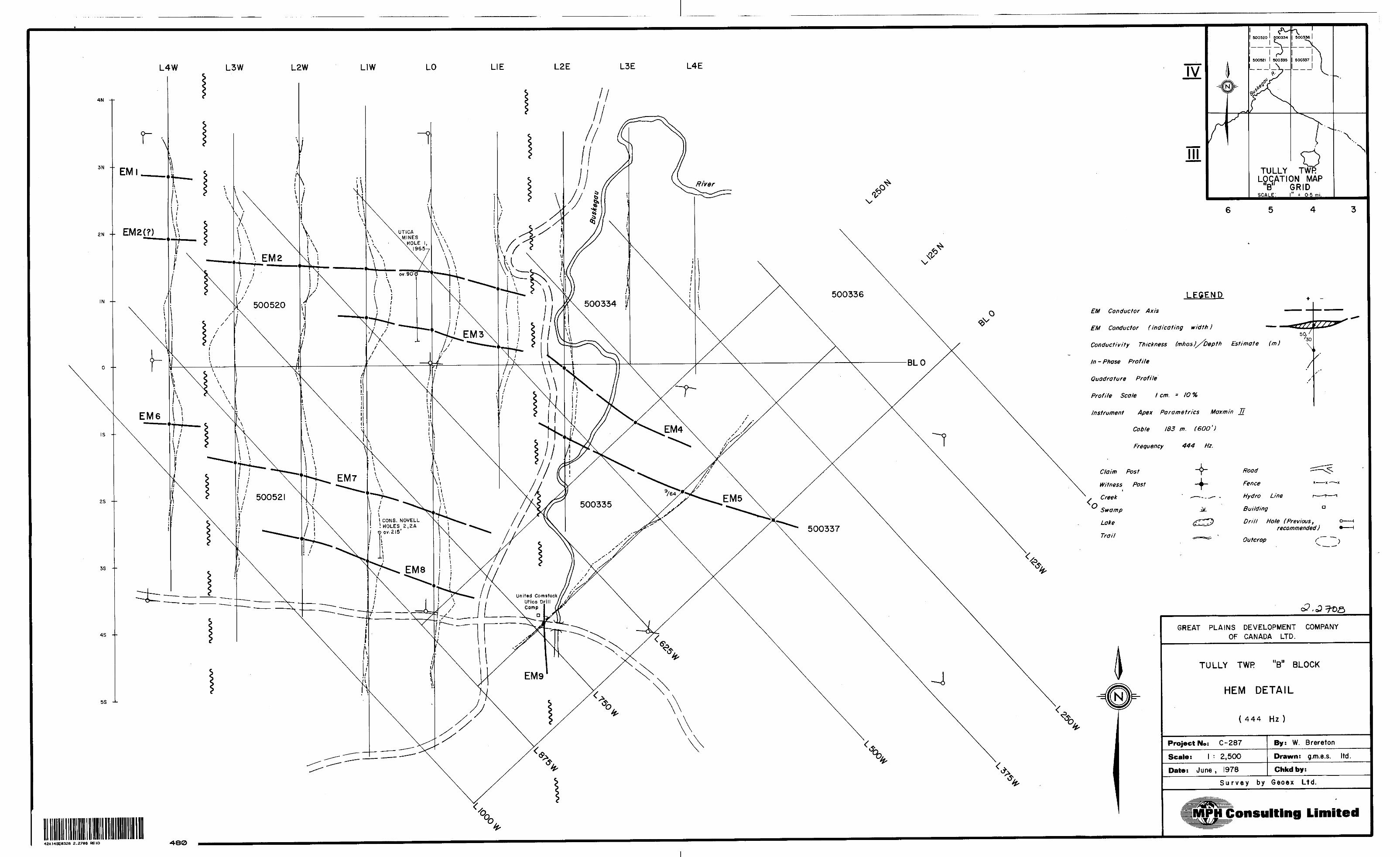
L4W L3W L2W L2E L3E L4E
4N -H
5S
EM Conductor Axis
I HOLES a, O ov.215 1
United Comstock Utica Drill Camp
D
TULLY TWR LOCATION MAP
M*"tll f*, r^ i M.
LEGEND
EM Conductor (indicating width) —
Conductivity Thickness (mhosJ/Depth Estimate (m)
In - Phase Profile
Quadrature Prof f le
Profile Scale t cm. * 10 ^
Instrument Apex Parametrics Maxmin 77
Cob f e 183 m. (6OO 1 )
Frequency 444 Hz.
-hRoad
Fence *— * —^
Hydro Line r—-r—i
Building a
Drill Hole (Previous, recommended)
Outcrop
42A14SE0328 2 .2708 REID •480
GREAT PLAINS DEVELOPMENT COMPANY OF CANADA LTD.
TULLY TWR "B" BLOCK
HEM DETAIL
(444 Hz)
Project No: C-287
Scale: l : 2,500
Date: J une , 1978
By: W. Brereton
Drawn: g .m.e.s. ltd
Chkdby:
Survey by Geoex Ltd,
Consulting Limited

4N
4S --
5S -1-
L4W L3W L2W LIW LIE L2E L3E L4E
O EM Conductor Axis
UTICAMINES
.\HOLE l, \ ^\ 1965
United ComstocK Utica Drill Camp
IV
TULLY TWR LOCATION MAP
B" GRIDSCALE: i" ? o -s mi.
LEGEND
EM Conductor (indicating width ) —
Conductivity Thickness (mhos)/ Depth Estimate (m)
In - Phase Profile
Quadrature Profile
Profile Scale t cm. = /0%
Instrument Apex Parametrics Maxmin 77
Cable 183 m, (6OO ')
//
Frequency 1777 Hz.
-f-f
Road
Fence
Hydro Line
Building
Drill Hole (Prevt'ous t recommended)
Outcrop
42AMSE8328 2.2768 REID 430
GREAT PLAINS DEVELOPMENT COMPANY OF CANADA LTD.
Mr-,11TULLY TWR B 1 BLOCK
HEM DETAIL
(1777 Hz
Project No: C -287
Scale: l : 2,500
Date: J une , 1978
By: W. Brereton
Drawn: g.m.e.s. ltd
Chkd by:
Su rvey by Geoex Ltd.
MPH Consulting Limited

222
0+
00
5W 10 W 15
W
8 N
8 N 222
Hz.
7 N
444
t 7 N
Hz.
BA
SE
L
INE
TIE
LIN
E
8 N
i \
8 N 4
44
Hz. 7
N
88
8
7 N
Hz.
0+
00
5W 10
W 5 W
8 N
i. i- 8 N
Hz.
7 N
i
/
i l l f l F 7
N
88
8Hz
.
BA
SE
L
INE
TIE
LIN
E
1777
i \1 f \ i \\ \ \ \ ' l \ i i l 1
e N
-* ——
——
'
i i i i i i \ \ \ \ \- \ i-
i i i i l i l \ \ \ f f / / 1 I \ \ -\ \ i i 1 l 1 i i i 1 \ \ \
i — i \\ 1 \ \ \ i 1 \ \ \ \ \ \ \ 1Hz. 7
N
\ \
s'
/i
A x -x
s
,xf
1 ——
——
t—
s \\ ,' 1
v\ . 1 l i ii \ \ \ \ . j l j 1 l
"~.V
.
\ ~
\(
/' 1 1 i
- '
^ x
\ '\
\ \ \ ' /
/'
1 i\ 1 i 1\ i . s
s/.x'
1 t i \ \ \
t i i i iV
t v \
\ ^ 7 X X ; 7 1 1
J
\
\ /"
/ 7 ——
— h
-i i^v.
' J t x l il
i V y /7l
/l
\ \ \ \ i \ i 1 i i l l i i i 1 i \ i i i i i i i i i i i i
8N n
~ H \\ \ \
177
1 i 1 \ 7
N 1 i\ f i•v \ 1"^ \ i
l i i i i l i i i i i i i i i i i i \ \ \ t i i i i i i t i i i i i i 1 i i i i i i i i i \ \ 5
Wi i l i i i i t i i i i i \ \ \ \ i i i i i ! \ \ \ \ \ \ \
\ \ i i ix
xx
xs \ \ —
——
i ——
— ( —
——
. ——
— ,
,0 w
RI
DL.
^- ^
\\\ \ t 1
i f
* j i
-
t 1 1 i 1 i
i l i i 1 l 1 1 1 1 1 i i i i i i i i i-i
-H 1
5 W
i i i i j i i
5 W
l—
i i l i i t i 1 l 1 ; i i i i i i \ \ \ \ i i i
7 N
i i \i \ i \ i \22
2
Hz.
444
Hz.
/ \ l \ i \ i
12 N
12
N
——
——
——
——
——
——
——
——
1 __
__
__
___
___
___
__
__
___
__
11 A
f-C
DM
OC
.
1 fi jl 1 tp i 1 t
•M f
i i i i ij
1
1 i i-
1 i \i \ i i
i i i i i i i
i i i i i ' i i i 1 1'
1 '
i '
1 l
rj ,
'
t i i J 1 i
i i i i i i i 4 1 i i i i i i 1 i l 1 i
1 ', i i i i
i i i i i
i i i
1 1
'!
1
ii
'l • i i
\ i
' 1
i1
l •i ii i .
•K*
t ^
——
——
— i —
——
——
——
—
, IC
——
——
——
——
. ——
—
12 N
-
222
Hz.
12
N-
444
H
12 N
- 1
777 H
z.
xv
i f*
n
. 1 1'
i
. 1 ' . - '
Hz.
10 W
h-
TIE
\J -T
V\J
l 1 l i i l i i
z.
888
Hz.
12
N
LIN
E
——
——
——
——
——
-
- .
l
i i i i i i j i i i 1 i 1
i1 1
' ' i i i i i i i t l i i— i i i
- i - 1 ;1 i i i i i i i i t i i i i
; .
t i \
i \ \ \
\ \ .——
——
——
—
o+oo 5
W
^ I.. .
i j^
t 1
1LI
NE
—
——
——
——
——
— —
——
——
——
——
—
ruw
12 N
-
888
Hz.
! LE
GE
ND
i i i 1 In
stru
men
t: M
oxm
in
II1 i '
Cabl
e Le
ngth
: l \
Freq
uenc
y :
22
2,
\ i i i i t 1 i i i i j In
phas
e - ^
^i i i
.i
. x,
Qua
drat
ure
-"^
j l i i i i i l \ P
rofil
e
Sca
le '
i i i i i i i i l 7 x j i i i i \ \ \ \ \ \ \ \ i i i i i 1
i i*
ic—
——
——
——
——
——
——
——
——
——
——
——
——
——
— -
——
——
——
b
Ml k.
i2 N
c ^?r
\W^
1777
Hz
. ^^^
40
0'
(12
2m
.)
44
4 ,
88
8,
1777
H
z.
—
^/'
^'
'^
s
1 cm
-
(^
' /^
%
| ——
——
——
——
——
——
——
——
——
——
——
——
——
——
——
——
——
——
——
——
——
——
|
IMP
HI
Consu
lting L
imite
d^fe
^JP
^G
REA
T P
LAIN
S
DE
VE
LOP
ME
NT
CO
MPA
NY
OF
CAN
ADA
LTD
.
MA
CD
IAR
MID
TW
P "A
" B
LOC
K
HE
M
DE
TA
IL
Sca
le:
1 ;
2,5
00
Dra
wn
by
'. g.
m.e
.s.
ltd.
App
rove
d b
y: W
. B
rere
ton
Date
! M
arch
1 1
978
Dra
win
g N
o.
| (j
'


