Download - 4G63 Transmission

22A-1
GROUP 22A
MANUAL TRANSMISSION (FF)
CONTENTS
GENERAL INFORMATION . . . . . . . . 22A-2
LUBRICANT. . . . . . . . . . . . . . . . . . . . 22A-2
SPECIAL TOOLS. . . . . . . . . . . . . . . . 22A-3
TROUBLESHOOTING . . . . . . . . . . . . 22A-4INTRODUCTION. . . . . . . . . . . . . . . . . . . . . 22A-4TROUBLESHOOTING STRATEGY . . . . . . 22A-4SYMPTOM CHART. . . . . . . . . . . . . . . . . . . 22A-4SYMPTOM PROCEDURES . . . . . . . . . . . . 22A-4
ON-VEHICLE SERVICE. . . . . . . . . . . 22A-8TRANSMISSION OIL LEVEL CHECK . . . . 22A-8
TRANSMISSION OIL REPLACEMENT. . . . 22A-8TRANSFER OIL CHECK. . . . . . . . . . . . . . . 22A-8TRANSFER OIL REPLACEMENT . . . . . . . 22A-8
TRANSMISSION CONTROL*. . . . . . . 22A-9REMOVAL AND INSTALLATION . . . . . . . . 22A-9SHIFT LEVER ASSEMBLY . . . . . . . . . . . . . 22A-12DISASSEMBLY AND REASSEMBLY . . . . . 22A-12
TRANSFER ASSEMBLY . . . . . . . . . . 22A-13REMOVAL AND INSTALLATION . . . . . . . . 22A-13
TRANSMISSION ASSEMBLY . . . . . . 22A-15REMOVAL AND INSTALLATION . . . . . . . . 22A-15
WANINGS REGARDING SERVICING OF SUPPLEMENTAL RESTRAINT SYSTEM (SRS) EQUIPPED VEHICLES
WARNING• Improper service or maintenance of any component of the SRS, or any SRS-related component, can lead to
personal injury or death to service personnel (from inadvertent firing of the air bag) or to the driver and paassenger (from rendering the SRS inoperative).
• Service or maintenance of any SRS component or SRS-related component must be performed only at an authorized MITSUBISHI dealer.
• MITSUBISHI dealer personnel must thoroughly review this manual, and especially its GROUP 52B - Supplemental Restraint System (SRS) before beginning any service or maintenance of any component of the SRS or any SRS-related component.
NOTEThe SRS includes the following components: SRS air bag control unit, SRS warning light, front impact sensors, air bag module,clock spring, and interconnecting wiring. Other SRS-related components (that may have to be removed/installed in connectionwith SRS service or maintenance) are indicated in the table of contents by an asterisk (*).

GENERAL INFORMATIONMANUAL TRANSMISSION (FF)22A-2
GENERAL INFORMATIONM1221000100677
The manual transmission come in two models, namely, F5M42 and W5M42.
LUBRICANTM1221000400203
Item SpecificationTransmission model F5M42 (2WD) W5M42 (4WD)Engine model 4G63-DOHC-MPI 4G69-SOHC-MIVE
CTransmission type 5-speed forward, 1-speed reverse constant meshTransmission gear ratio 1st 3.583
2nd 1.9473rd 1.3794th 1.0305th 0.820Reverse 3.363
Final reduction ration (Differential gear ratio) 4.625 4.687 4.352Speedmeter gear ratio 27/36
Item Specified lubricant Quantity LTransmission oil Gear oil API classification GL-4 SAE 75W-85W or 75W-90 2WD 2.2
4WD 2.3 Transfer oil <4WD> Hypoid gear oil API classification GL-5 SAE90 0.55

SPECIAL TOOLSMANUAL TRANSMISSION (FF) 22A-3
SPECIAL TOOLSM1221000600672
Tool Number Name UseMB991453 Engine hanger
assemblyWhen the engine hanger is used: Supporting the engine assembly during removal and installation of the transmission assemblyNOTE: Special tool MB991454 is a part of engine hanger attachment set MB991453.MB991454 Engine hanger
balancer
MB991527 Engine hanger
MB991895 Engine hanger
MB991928A: MB991929B: MB991930C: MB991931D: MB991932E: MB991933F: MB991934
Engine hangerA: Joint (50) ×2B: Joint (90) ×2C: Joint (140) ×2D: Foot (standard) ×4E: Foot (short) ×2F: Chain and hook
assembly
B991453
B991454
B991527
MB991895
B991928
A
BC
D
E
F
Slide bracket (HI)

TROUBLESHOOTINGMANUAL TRANSMISSION (FF)22A-4
TROUBLESHOOTINGINTRODUCTION
M1221006900660The manual transmission can exhibit any of the following symptoms: noise or vibration is generated, oil leaks, shifting gears is hard or troublesome, or the transmission jumps out of gear.The causes of these symptoms could come from: incorrect mounting, the oil level may be low, or a component of the transmission may be faulty.
TROUBLESHOOTING STRATEGYM1221007000585
Use these steps to plan your diagnostic strategy. If you follow them carefully, you will be sure that you have exhausted most of the possible ways to find a manual transmission fault.1. Gather information from the customer.2. Verify that the condition described by the
customer exists.3. Find the malfunction by following the Symptom
Chart.4. Verify malfunction is eliminated.
SYMPTOM CHARTM1221007100571
SYMPTOM PROCEDURES
INSPECTION PROCEDURE 1: Noise, Vibration
DIAGNOSIS
STEP 1. Check the idle speed.Q: Does the idle speed meet the standard values?
YES : Go to Step 2 .NO : Refer to GROUP 11A <4G63
Engine>P.11A-11 , or GROUP 11C <4G69 Engine>P.11C-14 , On-vehicle Service − Kerb Idle Speed Check.
STEP 2. Check whether the transaxle and engine mount is loose or damaged.Q: Are the transaxle and engine mount loose or
damaged?YES : Tighten or replace the part. Then go to Step
7 .NO : Go to Step 3 .
STEP 3. Check that the oil level is up to the lower edge of the filler plug hole.
Q: Is the oil level up to the lower edge of the filler plug hole?YES : Go to Step 4 .NO : Refill gear oil API classification GL-4 SAE
75W−85W or 75W−90. Then go to Step 7 .
SYMPTOM INSPECTION PROCEDURE
REFERENCE PAGE
Noise, Vibration 1 P.22A-4 Oil Leaks 2 P.22A-5 Hard Shifting 3 P.22A-6 Jumps Out of Gear 4 P.22A-7
AC102278AO
Filler plugTransmission oil
Filler plug hole

TROUBLESHOOTINGMANUAL TRANSMISSION (FF) 22A-5
STEP 4. Check for the specified oil.Q: Is the specified oil gear oil API classification GL-4
SAE 75W−85W or 75W−90?YES : Go to Step 5 .NO : If in doubt, replace the oil. Refer to P.22A-8.
Then go to Step 7 .
STEP 5. Remove the transmission. Check the end play of the input and output shafts.Q: Does the end play of the input and output shafts
meet the standard value?YES : Go to Step 6 .NO : Adjust the end play of the input and output
shafts. Then go to Step 7 .
STEP 6. Disassemble the transmission. Check the gears for wear and damage.Q: Are the gears worn or damaged?
YES : Replace the gears. Go to Step 7 .NO : Go to Step 7 .
STEP 7. Retest the systems.Q: Is the noise or vibration still there?
YES : Return to Step 1 .NO : The procedure is complete.
INSPECTION PROCEDURE 2: Oil Leaks
DIAGNOSIS
STEP 1. Visual check.Raise the vehicle, and check for oil leaks. If oil leak is difficult to locate, steam clean the transmission and drive the vehicle for at 10 minutes. Then check the leak again.
Q: Is the oil leak(s) found?YES : Go to Step 2 .NO : Check for the oil leaks around the engine.
Then go to Step 4 .
STEP 2. Visual check at the clutch housing.Q: Do oil leaks appear around the joint between the
engine and the clutch housing?
YES : Remove the transmission. Check the input shaft oil seal, and replace if necessary. Then go to Step 4 .
NO : Go to Step 3 .
STEP 3. Check the oil seal or O-ring for damage.Q: Is the oil seal or O-ring damaged?
YES : Replace the oil seal or the O-ring. Then go to Step 4 .
NO : Go to Step 4 .
STEP 4. Retest the system.Q: Is the oil still leaking?
YES : Return to Step 1 .NO : The procedure is complete.
TROUBLESHOOTINGMANUAL TRANSMISSION (FF)22A-6
INSPECTION PROCEDURE 3: Hard Shifting
DIAGNOSIS
STEP 1. Check the transmission controlQ: Are the shift cable and the select cable in good
condition?YES : Go to Step 2 .NO : Repair or replace the shift cable and the
select cable. Refer to P.22A-8. Then go to Step 7 .
STEP 2. Check the transmission oil.Q: Is the oil dirty?
YES : Replace the oil. Refer to P.22A-8. Then go to Step 7
NO : Go to Step 3 .
STEP 3. Check the clutch system.Q: Is the clutch system normal?
YES : Go to Step 4 .NO : Repair or replace the clutch system. Refer
to P.22A-8. Then go to Step 7 .
STEP 4. Remove and disassemble the transmission. Check the control housing.Q: Is the control housing in good condition?
YES : Go to Step 5 .NO : Repair or replace the control housing. Refer
to GROUP 22B, Transmission P.22B-43. Then go to Step 7 .
STEP 5. Check for poor meshing of worn synchronizer ring and gear cone.Q: Is poor meshing or worn synchronizer ring and
gear cone found?YES : Repair or replace the synchronizer ring and
gear cone. Then go to Step 7 .NO : Go to Step 6 .
STEP 6. Check the synchronizer spring for weakness.Q: Is the synchronizer spring weak?
YES : Replace the synchronizer spring. Then go to Step 7 .
NO : Go to Step 7 .
STEP 7. Retest the system.Q: Is the shifting of the gears still hard?
YES : Return to Step 1 .NO : The procedure is complete.

TROUBLESHOOTINGMANUAL TRANSMISSION (FF) 22A-7
INSPECTION PROCEDURE 4: Jumps Out of Gear
DIAGNOSIS
STEP 1. Check the transmission controlQ: Are the shift cable and the select cable in good
condition?YES : Go to Step 2 .NO : Repair or replace the shift cable and the
select cable. Refer to P.22A-8. Then go to Step 6 .
STEP 2. Remove and disassemble the transmission. Check the poppet spring for breakage.Q: Is the poppet spring broken?
YES : Replace the poppet spring. Refer to GROUP 22B, Transmission P.22B-14. Then go to Step 6 .
NO : Go to Step 3 .
STEP 3. Check the control housing.Q: Is the control housing in good condition?
YES : Go to Step 4 .NO : Repair or replace the control housing. Refer
to GROUP 22B, Transmission P.22B-14. Then go to Step 6 .
STEP 4. Check the gear shift forks for wear.Q: Is the gear shift forks worn?
YES : Replace the gear shift fork. Refer to GROUP 22B, Transmission P.22B-14. Then go to Step 6 .
NO : Go to Step 5 .
STEP 5. Check the clearance.Q: Is the clearance between the synchronizer hub and
sleeve excessive?YES : Replace the synchronizer hub or sleeve.
Refer to GROUP 22B, Input Shaft P.22B-25, Output Shaft P.22B-32. Then go to Step 6.
NO : Go to Step 6 .
STEP 6. Retest the system.Q: Does the transmission still jump out of gear?
YES : Return to Step 1 .NO : The procedure is complete.

ON-VEHICLE SERVICEMANUAL TRANSMISSION (FF)22A-8
ON-VEHICLE SERVICETRANSMISSION OIL LEVEL CHECK
M1221000900479
1. Remove the filler plug.2. Check that the oil level is up to the lower edge of
the filler plug hole.3. Check that the oil is not noticeably dirty.4. Tighten the filler plug to the specified torque.
Tightening torque: 32 ± 2 N⋅m
TRANSMISSION OIL REPLACEMENTM1221001000402
1. Remove the filler plug.2. Remove the drain plug and drain the oil.3. Tighten the drain plug to the specified torque.
Tightening torque: 32 ± 2 N⋅m4. Fill with gear oil API classification GL-4 SAE
75W-85W or 75W-90 until the level comes to the lower portion of filler plug hole.Quantity: 2.2 L <2WD>Quantity: 2.3 L <4WD>
5. Tighten the filler plug to the specified torque.Tightening torque: 32 ± 2 N⋅m
TRANSFER OIL CHECKM1221001100108
1. Remove the filler plug.2. Check that the oil level is up to the lower edge of
the filler plug hole.3. Check that the oil is not noticeably dirty.4. Tighten the filler plug to the specified torque.
Tightening torque: 32 ± 2 N⋅m
TRANSFER OIL REPLACEMENTM1221001200086
1. Remove the filler plug.2. Remove the drain plug and drain the oil.3. Tighten the drain plug to the specified torque.
Tightening torque: 32 ± 2 N⋅m4. Fill with hypoid gear oil API classification GL-5
SAE90 until the level comes to the lower portion of filler plug hole.
Quantity: 0.55 L5. Tighten the filler plug to the specified torque.
Tightening torque: 32 ± 2 N⋅m
AC210553AB
Filler plug hole
Filler plugTransmission oil
AC210554
Drain plug
Filler plug
AB
AC210553AC
Filler plug hole
Filler plugTransfer oil
AC210555
Filler plug
Drain plug
AB

TRANSMISSION CONTROLMANUAL TRANSMISSION (FF) 22A-9
TRANSMISSION CONTROLREMOVAL AND INSTALLATION
M1221003800578
WARNINGBe careful not to subject the SRS-ECU to any shocks during removal and installation of the shift cable and select cable assembly.
Pre-removal and Post-installation Operation• Air Cleaner Assembly Removal and Installation (Refer to
GROUP 15, Air Cleaner P.15-3<4G63>, P.15-4<4G69>).• Battery and Battery Tray Removal and Installation.
AC309478AB
1
12 ± 2 N·m
12 ± 2 N·m
11
45
3
6
12
78N
10
79
2
Gearshift cable and select cable assembly removal steps
1. Gearshift lever knob2. Sleeve• Front floor console (Refer to
GROUP 52A P.52A-14).3. Select cable connection (Gearshift
lever side)>>B<< 4. Gearshift cable clip
5. Gearshift cable connection (Gearshift lever side)
• SRS-ECU (Refer to GROUP 52B P.52B-178).
6. Console side cover bracket7. Snap pin
<<A>> >>A<< 8. Gearshift link clip<<A>> >>A<< 9. Select cable connection
(Transmission side)
<<A>> >>A<< 10. Gearshift cable connection (Transmission side)
>>A<< 11. Gearshift cable and select cable assemblyGearshift lever assembly removal steps
1. Gearshift lever knob2. Sleeve• Front floor console (Refer to
GROUP 52A P.52A-14).3. Select cable connection (Gearshift
lever side)>>B<< 4. Gearshift cable clip
5. Gearshift cable connection (Gearshift lever side)
12. Gearshift lever assembly
Gearshift cable and select cable assembly removal steps

TRANSMISSION CONTROLMANUAL TRANSMISSION (FF)22A-10
REMOVAL SERVICE POINTS<<A>> GEARSHIFT LINK CLIP/SELECT CABLE CONNECTION (TRANSMISSION SIDE)/GEAR SHIFT CABLE CONNECTION (TRANSMISSION SIDE) REMOVAL
Push up the claws of the gearshift link clip using a screwdriver, etc., and then remove the gearshift link clip from the bracket together with the cables.
INSTALLATION SERVICE POINTS>>A<< GEARSHIFT CABLE AND SELECT CABLE ASSEMBLY/GEARSHIFT CABLE CONNECTION (TRANSMISSION SIDE)/SELECT CABLE CONECTION (TRANSMISSION SIDE)/GEARSHIFT LINK CLIP INSTALLATION
1. Set the transmission side shift lever and the passenger compartment side shift lever to the neutral position.
2. Install the painted part of the shift cable end (transmission side) and painted part of the select cable (transmission side) facing the snap pin.CAUTION
Insert thoroughly the gearshift link clip, shift cable and select cable until they click in place.3. After installing the new gearshift link clip to the
cable bracket of the transmission, install the shift cable and select cable to the cable bracket.NOTE: The clip is reversible.
4. Move the shift lever to all positions and check that the operation is smooth.
AC210556Gearshift link clip
Gearshift cable, Select cableClaws
AB
AC210557ABNeutral position
Select lever
AC210558
Shift cable, Select cable
New gearshift link clip
Cable bracket
AB

TRANSMISSION CONTROLMANUAL TRANSMISSION (FF) 22A-11
>>B<< GEAR SHIFT CABLE CLIP INSTALLATION
1. Make sure that there is no excessive play at the shift cable end gearshift cable clip. If there is excessive play or the gearshift cable clip is disengaged from the shift cable end, check the clip opening gap. If the gap is more than 9.5 mm, squeeze the gearshift cable clip until the relaxed gap reaches 5 to 8 mm.
2. Engage the gearshift cable clip with the shift cable hook securely, and push the gearshift cable clip with your thumbs until it clicks in place.
3. Install the shift cable to the shift lever.
AC210559AB
9.5 mm 5 - 8 mm
AC210560AB

TRANSMISSION CONTROLMANUAL TRANSMISSION (FF)22A-12
SHIFT LEVER ASSEMBLY
DISASSEMBLY AND REASSEMBLYM1221004000207
AC309326AB
78
8
6
109
5
11
3423
1
10 ± 1 N·m
14 ± 2 N·m
Disassembly steps1. Gearshift link bolt2. Gearshift select lever3. Gearshift link bushing4. Gearshift lever spring5. Gearshift link collar6. Bolt
7. Gearshift lever8. Gearshift link bushing9. Gearshift lever bracket distance
piece10. Gearshift link bushing11. Gearshift lever bracket
Disassembly steps (Continued)

TRANSFER ASSEMBLYMANUAL TRANSMISSION (FF) 22A-13
TRANSFER ASSEMBLYREMOVAL AND INSTALLATION
M1221003200059
CAUTION*: Indicates parts which should be temporarily tightened, and then fully tightened after installing the engine into the vehicle.
Pre-removal and Post-installation Operation• Front Under Cover Removal and Installation (Refer to
GROUP 51, Front Bumper P.51-3).• Side Under Cover Removal and Installation (Refer to
GROUP 51, Front Bumper P.51-3).• Engine Coolant Draining and Supplying (Refer to GROUP
14, On-vehicle Service P.14-17).• Transfer Oil Draining and Supplying (Refer to P.22A-8).• Drive Shaft, Output Shaft Removal and Installation (Refer
to GROUP 26 P.26-15).• Front Exhaust Pipe Removal and Installation (Refer to
GROUP 15, Exhaust Pipe and Main Muffler P.15-13).• Propeller Shaft Removal and Installation (Refer to
GROUP 25 P.25-3).
AC210286
1
2
9
4
8 N
69 ± 10 N·m
69 ± 10 N·m
52 ± 7 N·m*
52 ± 7 N·m*
69 ± 10 N·m
69 ± 10 N·m
30 ± 3 N·m
9.0 ± 2.0 N·m
AC
N
N
10
3
5
9.0 ± 2.0 N·m
30 ± 3 N·m
7
6
Removal steps1. Water return tube assembly2. Gasket
3. Water feed tube assembly4. Gasket
Removal steps (Continued)
TRANSFER ASSEMBLYMANUAL TRANSMISSION (FF)22A-14
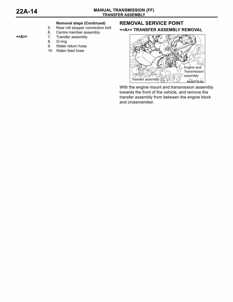
REMOVAL SERVICE POINT<<A>> TRANSFER ASSEMBLY REMOVAL
With the engine mount and transmission assembly towards the front of the vehicle, and remove the transfer assembly from between the engine block and crossmember.
5. Rear roll stopper connection bolt6. Centre member assembly
<<A>> 7. Transfer assembly8. O-ring9. Water return hose10. Water feed hose
Removal steps (Continued)
AC207772Transfer assembly
Engine and Transmission assembly
AC

TRANSMISSION ASSEMBLYMANUAL TRANSMISSION (FF) 22A-15
TRANSMISSION ASSEMBLYREMOVAL AND INSTALLATION
M1221002700318
CAUTION*: Indicates parts which should be temporarily tightened, and then fully tightened after installing the engine into the vehicle.
Pre-removal and Post-installation Operation• Air Cleaner assembly, Air Cleaner Bracket Removal and
Installation (Refer to GROUP 15, Air Cleaner P.15-3<4G63>, P.15-4<4G69>).
• Battery and Battery Tray Removal and Installation.• Front Under Cover Removal and Installation (Refer to
GROUP 51, Front Bumper P.51-3).• Side Under Cover Removal and Installation (Refer to
GROUP 51, Front Bumper P.51-3).• Transfer Oil Draining and Supplying <4WD> (Refer to
P.22A-8).• Drive Shaft Removal and Installation (Refer to GROUP 26
P.26-15).• Output Shaft Removal and Installation <4WD> (Refer to
GROUP 26 P.26-15).• Front Exhaust Pipe Removal and Installation (Refer to
GROUP 15, Exhaust Pipe and Main Muffler P.15-13).• Propeller Shaft Removal and Installation <4WD> (Refer to
GROUP 25 P.25-3).
AC210287AB
<4WD>
<2WD>
70 ± 10 N·m
70 ± 10 N·m
70 ± 10 N·m
18 ± 3 N·m
18 ± 3 N·m
1
2
3
4
5
5
6
18 ± 3 N·m
7
78

TRANSMISSION ASSEMBLYMANUAL TRANSMISSION (FF)22A-16
Removal steps1. Transmission harness clamp2. Back-up lamp switch connector3. Vehicle speed sensor connector4. Clutch release cylinder and clutch
oil pipe5. Snap pin6. Cable bracket and cable assembly
<Transmission side>
• Transfer assembly (Refer to P.22A-13).
7. Rear roll mount bracket8. Rear roll mount adapter bracket
<4WD><<A>> • Engine and transmission
assembly supporting
Removal steps (Continued)
AC210288
<4WD>
<2WD>
AB
13
14
14
9.0 ± 1.0 N·m
9.0 ± 1.0 N·m
26 ± 5 N·m
44 ± 10 N·m
22 ± 4 N·m
15
48 ± 5 N·m
48 ± 5 N·m
48 ± 5 N·m
948 ± 5 N·m
9
9
48 ± 5 N·m
10
11
12
11
16
47 ± 7 N·m*
82 ± 7 N·m*
Removal steps9. Transmission assembly upper part
coupling bolts• Starter coupling bolts (Refer to
GROUP 16 P.16-22<4G63>, P.16-23<4G69> ).
<<A>> 10. Transmission mounting assembly>>B<< 11. Transmission mounting stopper
12. Transmission mounting
<<B>> • Engine assembly supporting<<C>> • Clutch release bearing connection
>>A<< 13. Transmission housing front lower cove stay <4WD>
14. Flywheel housing front lower cover
15. Transmission assembly lower part coupling bolts
16. Transmission assembly
Removal steps (Continued)

TRANSMISSION ASSEMBLYMANUAL TRANSMISSION (FF) 22A-17
REMOVAL SERVICE POINTS<<A>> ENGINE AND TRANSMISSION ASSEMBLY SUPPORTING/TRANSMISSION MOUNT ASSEMBLY REMOVAL
While supporting the engine and transmission assembly with a garage jack, remove the transmission mount assembly.
<<B>> ENGINE ASSEMBLY SUPPORT
1. <Engine hanger (special tool MB991895) is used>(1) Set special tool MB991895 to the strut
mounting nuts and the radiator support upper insulator mounting bolts, which are located in the engine compartment, as shown.
(2) Set special tools MB991454 to hold the engine/transmission assembly.
2. <Engine hanger (special tool MB991928) is used>(1) Assemble the engine hanger (special tool
MB991928). Set following parts to the base hanger.
• Slide bracket (HI)• Foot (standard) (MB991932)• Joint (90) (MB991930)• Joint (50) (MB991929)
(2) Set the engine hanger (special tool MB991928) to the strut mounting nuts and the radiator support upper insulator mounting bolts, which are located in the engine compartment, as shown.NOTE: Adjust the engine hanger balance by sliding the slide bracket (HI).
(3) Set special tools MB991454 to hold the engine/transmission assembly.
AC210384
Garage jack
Engine and transmission assembly
AB
AC210400AB
AC210388AB
MB991527
MB991454
MB991895
AC212277
Front sideSlide bracket (HI)
Joint (50)(MB991929)
Joint (90)(MB991930)
Foot (Standard)(MB991932)
Foot (Standard)(MB991932)
AD
AC210400AB
AC210392
MB991928 Slide bracket (HI)
MB991929
MB991932MB991932MB991930
MB991934
MB991527MB991454AF
TRANSMISSION ASSEMBLYMANUAL TRANSMISSION (FF)22A-18
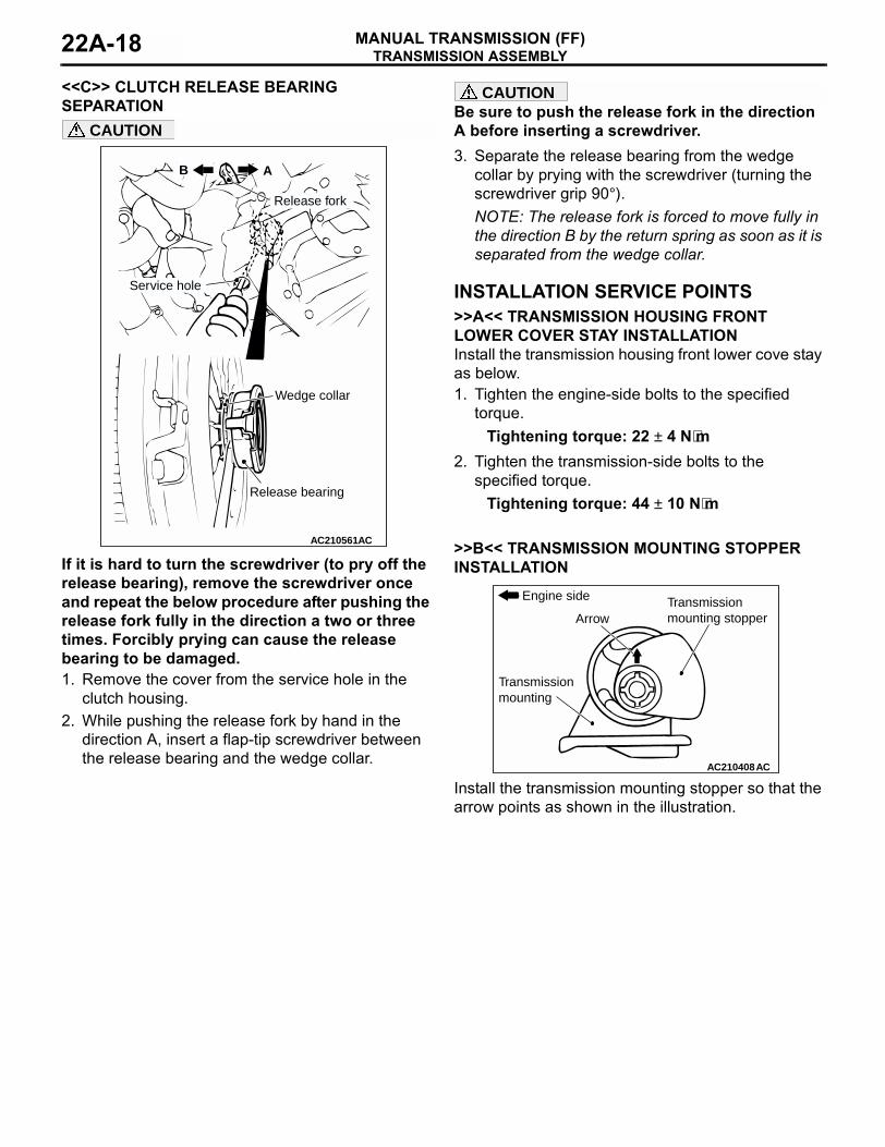
<<C>> CLUTCH RELEASE BEARING SEPARATION
CAUTION
If it is hard to turn the screwdriver (to pry off the release bearing), remove the screwdriver once and repeat the below procedure after pushing the release fork fully in the direction a two or three times. Forcibly prying can cause the release bearing to be damaged.1. Remove the cover from the service hole in the
clutch housing.2. While pushing the release fork by hand in the
direction A, insert a flap-tip screwdriver between the release bearing and the wedge collar.
CAUTIONBe sure to push the release fork in the direction A before inserting a screwdriver.3. Separate the release bearing from the wedge
collar by prying with the screwdriver (turning the screwdriver grip 90°).NOTE: The release fork is forced to move fully in the direction B by the return spring as soon as it is separated from the wedge collar.
INSTALLATION SERVICE POINTS>>A<< TRANSMISSION HOUSING FRONT LOWER COVER STAY INSTALLATIONInstall the transmission housing front lower cove stay as below.1. Tighten the engine-side bolts to the specified
torque.Tightening torque: 22 ± 4 N⋅m
2. Tighten the transmission-side bolts to the specified torque.
Tightening torque: 44 ± 10 N⋅m
>>B<< TRANSMISSION MOUNTING STOPPER INSTALLATION
Install the transmission mounting stopper so that the arrow points as shown in the illustration.
AC210561AC
Wedge collar
Release bearing
AB
Service hole
Release fork
AC210408
Transmissionmounting stopperArrow
Transmissionmounting
Engine side
AC


