
Dr. Rakhesh Singh Kshetrimayum
5. Plane Electromagnetic Waves
Dr. Rakhesh Singh Kshetrimayum
3/19/20141 Electromagnetic Field Theory by R. S. Kshetrimayum

5.1 Introduction Electromagnetic
Waves
Plane waves Poyntingvector
Plane waves in various media
3/19/2014Electromagnetic Field Theory by R. S. Kshetrimayum2
Polarization Lossless medium
Good conductor
Fig. 5.1 Plane Waves
Lossyconducting medium
Good dielectric
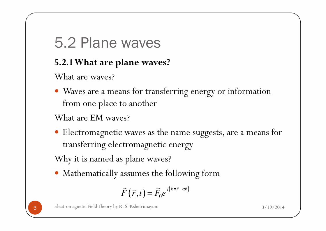
5.2 Plane waves5.2.1 What are plane waves?
What are waves?
Waves are a means for transferring energy or information from one place to another
What are EM waves?What are EM waves?
Electromagnetic waves as the name suggests, are a means for transferring electromagnetic energy
Why it is named as plane waves?
Mathematically assumes the following form
3/19/20143 Electromagnetic Field Theory by R. S. Kshetrimayum
( ) ( )0
,j k r t
F r t F eω• −
=r rr rr

5.2 Plane waves where is the wave vector and it points in the direction of wave propagation,
is the general position vector,
ω is the angular frequency, and
is a constant vector
kr
rr
Fr
3/19/2014Electromagnetic Field Theory by R. S. Kshetrimayum4
is a constant vector
denotes either an electric or magnetic field ( F is a notation for field not for the force)
For example, in electromagnetic waves, is either vector electric ( ) or magnetic field ( )
0F
0Fr
0Fr
0Er
0Hr

5.2 Plane waves In rectangular or Cartesian coordinate system
x y zk k x k y k z= + +r ) ) )
r xx yy zz= + +r ) ) )
( ) ( ) ( )22 22 2
k k k k k k ω µε⇒ = • = + + =r r
3/19/2014Electromagnetic Field Theory by R. S. Kshetrimayum5
Note that the constant phase surface for such waves
( ) ( ) ( )22 22 2
x y zk k k k k k ω µε⇒ = • = + + =
( ) ( ) tanx y z x y zk r k x k y k z xx yy zz k x k y k z con t• = + + • + + = + + =r r ) ) ) )) )

5.2 Plane waves defines a plane surface and hence the name plane waves
Since the field strength is uniform everywhere it is also known as uniform plane waves
A plane wave is a constant-frequency wave whose wavefronts (surfaces of constant phase) are infinite parallel
3/19/2014Electromagnetic Field Theory by R. S. Kshetrimayum6
wavefronts (surfaces of constant phase) are infinite parallel planes
of constant amplitude normal to the phase velocity vector
For plane waves from the Maxwell’s equations, the following relations could be derived (see Example 4.3)
; ; 0; 0k E H k H E k E k Hωµ ωε× = × = − • = • =r r r rr r r r r r

5.2 Plane wavesProperties of a uniform plane wave:
Electric and magnetic field are perpendicular to each other
No electric or magnetic field in the direction of propagation (Transverse electromagnetic wave: TEM wave)
The value of the magnetic field is equal to the magnitude of
3/19/2014Electromagnetic Field Theory by R. S. Kshetrimayum7
The value of the magnetic field is equal to the magnitude of the electric field divided by η0 (~377 Ohm) at every instant (magnetic field amplitude is much smaller than the electric field amplitude)

5.2 Plane waves The direction of propagation is in the same direction as Poynting vector
The instantaneous value of the Poynting vector is given by E2/η0, or H
2η0
The average value of the Poynting vector is given by E2/2η0,
3/19/2014Electromagnetic Field Theory by R. S. Kshetrimayum8
The average value of the Poynting vector is given by E2/2η0, or H2η0/2
The stored electric energy is equal to the stored magnetic energy at any instant

5.2 Plane waves5.2.2 Wave polarization
Polarization of plane wave refers to the orientation of electric field vector, which may be in fixed direction or
may change with time
3/19/2014Electromagnetic Field Theory by R. S. Kshetrimayum9
may change with time
Polarization is the curve traced out by the tip of the arrow representing the instantaneous electric field
The electric field must be observed along the direction of propagation

5.2 Plane wavesTypes of
polarization
Linear polarized Circularly Elliptically
3/19/2014Electromagnetic Field Theory by R. S. Kshetrimayum10
Linear polarized (LP)
Circularly polarized (CP)
Elliptically polarized (EP)
RHCPLHCP RHEP LHEP

5.2 Plane waves If the vector that describes the electric field at a point in space varies as function of time and
is always directed along a line
which is normal to the direction of propagation
3/19/2014Electromagnetic Field Theory by R. S. Kshetrimayum11
which is normal to the direction of propagation
the field is said to be linearly polarized
If the figure that electric field trace is a circle (or ellipse), then, the field is said to be circularly (or elliptically) polarized

5.2 Plane waves Besides, the figure that electric field traces is circle and anticlockwise (or clockwise) direction, then, electric field is also said to be right-hand (or left-hand) circularly polarized wave (RHCP/LHCP)
Besides, the figure that electric field traces is ellipse and
3/19/2014Electromagnetic Field Theory by R. S. Kshetrimayum12
Besides, the figure that electric field traces is ellipse and anticlockwise (or clockwise) direction, then, electric field is also said to be right-hand (or left-hand) elliptically polarized (RHEP/LHEP)

5.2 Plane waves Let us consider the superposition of
a x- linearly polarized wave with complex amplitude Ex and
a y- linearly polarized wave with complex amplitude Ey,
both travelling in the positive z-direction
Note that E and E may be varying with time for general
3/19/2014Electromagnetic Field Theory by R. S. Kshetrimayum13
Note that Ex and Ey may be varying with time for general case
so we may choose it for a particular instant of time
Note that since the electric field is varying with both space and time

5.2 Plane waves Easier to analyze at a particular instant of time first
And add the time dependence later
The total electric field can be written as
( ) ( ) ( ) zjj
y
j
x
zj
yx eyeExeEeyExEzE yx βφφβ −− +=+= ˆˆˆˆ00
r
3/19/2014Electromagnetic Field Theory by R. S. Kshetrimayum14
Note Ex and Ey may be complex numbers and
Ex0 and Ey0 are the amplitudes of Ex and Ey
( ) ( ) ( )yxyx eyeExeEeyExEzE 00

5.2 Plane waves and are the phases of Ex and Ey
Putting in the time dependence and taking the real part, we have,
A number of possibilities arises:
( ) ( ) ( )yztExztEtzE yyxxˆcosˆcos, 00 φβωφβω +−++−=
r
xφ yφ
3/19/2014Electromagnetic Field Theory by R. S. Kshetrimayum15
A number of possibilities arises:
Linearly polarized (LP) wave:
If both Ex and Ey are real (say Ex = Eox and Ey = Eoy), then,
( ) ( ) ( ) zj
yx
zj
yxLP eyExEeyExEzEββ −− +=+= ˆˆˆˆ
00
r

5.2 Plane waves
Putting in the time dependence and taking the real part, we have,
The amplitude of the electric field vector is given by
( ) ( ) ( )yztExztEtzE yxLPˆcosˆcos, 00 βωβω −+−=
r
3/19/2014Electromagnetic Field Theory by R. S. Kshetrimayum16
which is a straight line directed at all times along a line that makes an angle θ with the x-axis given by the following relation
01 1
0
tan tany y
LP
x x
E E
E Eθ − −
= =
( ) ( ) ( ) ( )ztEEtzE yxLP βω −+= cos,2
0
2
0
r

5.2 Plane waves If Ex ≠ 0 and Ey = 0,
we have a linearly polarized plane wave in x- direction
( ) ( )xztEtzE oxLPˆcos, βω −=
r
3/19/2014Electromagnetic Field Theory by R. S. Kshetrimayum17

5.2 Plane waves Easier to fix space to see the polarization
For a fixed point in space (say z=0),
For all times, electric field will be directed along x-axis
( ) ( )xtEtzE oxz
LPˆcos,
0ω=
=
r
3/19/2014Electromagnetic Field Theory by R. S. Kshetrimayum18
For all times, electric field will be directed along x-axis
hence, the field is said to be linearly polarized along the x-direction

5.2 Plane waves Fig. 5.2 (a) LP wave
3/19/2014Electromagnetic Field Theory by R. S. Kshetrimayum19

5.2 Plane wavesCircularly polarized (CP) wave:
Now consider the case Ex = j Ey = Eo, where Eo is real so that
0 20 0
; ;j
j
x yE E e E E e
π−
= =
3/19/2014Electromagnetic Field Theory by R. S. Kshetrimayum20
The time domain form of this field is (putting in the time dependence and taking the real part)
0 0x y
ˆ ˆ( )j z
RHCP oE E x jy eβ−= −
r
ˆ ˆ( , ) [ cos( ) cos( )]2
RHCP oE z t E x t z y t z
πω β ω β= − + − −
r

5.2 Plane waves Note that x- and y-components of the electric field have the
same amplitude
but are 900 out of phase
Let us choose a fixed position (say z=0), then,
3/19/2014Electromagnetic Field Theory by R. S. Kshetrimayum21
which shows that the polarization rotates with uniform angular velocity ω in anticlockwise direction
for propagation along positive z-axis
( )1 1sintantan tan
cosRHCP
tt t
t
ωθ ω ω
ω− −
= = =

5.2 Plane waves An observer sitting at z=0 will see
the electric field rotating in a circle and
the field never goes to zero
Since the fingers of right hand point in the direction of rotation of the tip of the electric field vector
3/19/2014Electromagnetic Field Theory by R. S. Kshetrimayum22
rotation of the tip of the electric field vector
when the thumb points in the direction of propagation,
this type of wave is referred to as right hand circularly polarized wave (RHCP wave)

5.2 Plane waves Fig. 5.2 (b) RHCP wave
3/19/2014Electromagnetic Field Theory by R. S. Kshetrimayum23
x
y

5.2 Plane wavesElliptically polarized (EP) wave:
Now, consider a more general case of EP wave,
when the amplitude of the electric field in the x- and y-directions are not equal in amplitude and
3/19/2014Electromagnetic Field Theory by R. S. Kshetrimayum24
amplitude and
phase
unlike CP wave, so that,
Putting in the time dependence and taking the real part, we have,
( ) ( ) zjj
EP eyAexzEβφ −+= ˆˆ
r
( ) ( ) ( )yztAxzttzE EPˆcosˆcos, φβωβω +−+−=
r

5.2 Plane waves If φ is in the upper half of the complex plane
then the wave is LHEP
whereas φ is in the lower half of the complex plane, then the wave is RHEP
Let us choose a fixed position (say z=0) like in the CP case,
3/19/2014Electromagnetic Field Theory by R. S. Kshetrimayum25
Let us choose a fixed position (say z=0) like in the CP case, then,
Some particular cases:
( ) ( )0
ˆ ˆcos cosEP
zE t x A t yω ω φ
== + +
r

5.2 Plane waves
( ) ( ) ( )
( )( ) ( )
00
00
ˆ ˆ( ) 1, 0; cos
ˆ ˆ( ) 1, ; cos
z
z
a A E E t x y LP
b A E E t x y LP
φ ω
φ π ω
π
=
=
= = = +
= = = −
r
r
r
3/19/2014Electromagnetic Field Theory by R. S. Kshetrimayum26
( ) ( ) ( )
( ) ( ) ( )
00
00
ˆ ˆ( ) 1, ; cos sin2
ˆ ˆ( ) 1, ; cos sin2
z
z
c A E E t x y t LHCP
d A E E t x y t RHCP
πφ ω ω
πφ ω ω
=
=
= = = −
= = − = +
r
r

5.2 Plane waves
( ) ( ) ( )
( ) ( ) ( )
( ) ( )
00
00
0
ˆ ˆ( ) 3, ; cos 3sin2
ˆ ˆ( ) 0.5, ; cos 0.5sin2
ˆ ˆ( ) 1, ; cos cos4 4
z
z
e A E E t x y t LHEP
f A E E t x y t RHEP
g A E E t x y t LHEP
πφ ω ω
πφ ω ω
π πφ ω ω
=
=
= = = −
= = − = +
= = = + +
r
r
r
3/19/2014Electromagnetic Field Theory by R. S. Kshetrimayum27
( ) ( )
( ) ( )
00
00
ˆ ˆ( ) 1, ; cos cos4 4
ˆ ˆ( ) 1, 3 ; cos cos 34 4
z
z
g A E E t x y t LHEP
h A E E t x y t RHEP
φ ω ω
π πφ ω ω
=
=
= = = + +
= = − = + −
r

5.2 Plane waves Fig. 5.2 (c) LHEP wave
Direction of propagation
3/19/2014Electromagnetic Field Theory by R. S. Kshetrimayum28
Electric field
Magnetic field at each point is orthogonal to the electric field
x
y

5.3 Poynting vector & power flow in EM fields
The rate of energy flow per unit area in a plane wave is described by a vector termed as Poynting vector which is basically curl of electric field intensity vector and magnetic field intensity vector
3/19/2014Electromagnetic Field Theory by R. S. Kshetrimayum29
The magnitude of Poynting vector is the power flow per unit area and
it points along the direction of wave propagation vector
*S E H= ×r r r

5.3 Poynting vector & power flow in EM fields
The average power per unit area is often called the intensity of EM waves and it is given by
Let us try to derive the point form of Poynting theorem from
( )*1Re
2avgS E H= ×r r r
3/19/2014Electromagnetic Field Theory by R. S. Kshetrimayum30
Let us try to derive the point form of Poynting theorem from two Maxwell’s curl equations
t
HE
∂
∂−=×∇
rr
µ Jt
EH
rr
r+
∂
∂=×∇ ε

5.3 Poynting vector & power flow in EM fields
From vector analysis,
We can further simplify
)()()()()( Jt
EE
t
HHHEEHHE
rr
rr
rrrrrrr+
∂
∂•−
∂
∂−•=×∇•−×∇•=ו∇ εµ
( )AAtt
AA
rrr
rQ •
∂
∂=
∂
∂•
2
1
3/19/2014Electromagnetic Field Theory by R. S. Kshetrimayum31
Basically a point relation It should be valid at every point in space at every instant of time
( ) ( ) ( )2 2
E H H H E E E Jt t
µ ε∂ ∂∴∇ • × = − • − • − •
∂ ∂
r r r r r r r r
( )AAtt
AQ •∂
=∂
•2

5.3 Poynting vector & power flow in EM fields
The power is given by the integral of this relation of Poynting vector over a volume as follows
We can interchange the volume integral and partial
∫∫∫ •−•∂
∂−•
∂
∂−=
VVV
dvJEdvEEt
dvHHt
rrrrrr)(
2)(
2
εµ( ) ( ) ∫∫∫ •=•×=ו∇SSV
sdSsdHEdvHErrrrrrr
3/19/2014Electromagnetic Field Theory by R. S. Kshetrimayum32
We can interchange the volume integral and partial derivative w.r.t. time
∫∫∫∫ −∂
∂−
∂
∂−=•
VVVS
dvEdvEt
dvHt
sdS 222
2
1
2
1σεµ
rr

5.3 Poynting vector & power flow in EM fields
This is the integral form of Poynting vector and power flow in EM fields
Poynting theorem states that
the power coming out of the closed volume is equal to
the total decrease in EM energy per unit time i.e. power loss
3/19/2014Electromagnetic Field Theory by R. S. Kshetrimayum33
the total decrease in EM energy per unit time i.e. power loss from the volume which constitutes of rate of decrease in magnetic energy stored in the volume
rate of decrease in electric energy stored in the volume
Ohmic power loss (energy converted into heat energy per unit time) in the volume

5.3 Poynting vector & power flow in EM fields
Now going back to the last four points of plane waves: The direction of propagation is in the same direction as of Poynting vector
The instantaneous value of the Poynting vector is given by E2/η0, or H
2η0
3/19/2014Electromagnetic Field Theory by R. S. Kshetrimayum34
E / 0, or H 0
The average value of the Poynting vector is given by E2/2η0, or H2η0/2
The stored electric energy is equal to the stored magnetic energy at any instant

5.3 Poynting vector & power flow in EM fields
Let us assume a plane wave traveling in the +z direction in free space, then
The instantaneous value of the Poynting vector:
0 0
0 0
0
;jk zj z j zz E
E E e E e H eβ β
η−− −×
= = =
r)r r r r
3/19/2014Electromagnetic Field Theory by R. S. Kshetrimayum35
The instantaneous value of the Poynting vector:
( ) ( ) ( )
( ) ( ) ( )0
2
0
0
00
0
0000
00
00
00
ˆˆˆˆ
ˆ1ˆ
ηηη
ηηββ
zEEEzzEEEEz
EzEeEz
eEHESzjzj
rrrrrrr
rrr
rrrr
=•
=•−•
=
××=
××=×= −∗

5.3 Poynting vector & power flow in EM fields
o Note that the direction of Poynting vector is also in the z-direction same as that of the wave vector
o The average value of the Poynting vector:
( )2
0
2
0ˆˆ
Re1
Re1 zEzE
HESavg
rrrrr
=
=×= ∗
3/19/2014Electromagnetic Field Theory by R. S. Kshetrimayum36
o Stored Electric Energy:
o Stored Magnetic Energy:
( )00 2
Re2
Re2 ηη
HESavg =
=×=
2
0
1
2e
w Eε=
2
2 2 20
0 0 0 02
0 0
1 1 1 1
2 2 2 2m e
Ew H E E w
εµ µ µ ε
η µ= = = = =

5.4 Plane waves in various media
A media in electromagnetics is characterized by three parameters: ε, µ and σ
5.4.1 Lossless medium In a lossless medium,
ε and µ are real, σ=0, so β is real ( )ωεσωµγ jj +=2Q
3/19/2014Electromagnetic Field Theory by R. S. Kshetrimayum37
ε and µ are real, σ=0, so β is real
Assume the electric field with only x- component, no variation along x- and y-axis and propagation along z-axis, i.e.,
0E E
x y
∂ ∂= =
∂ ∂
r r
( )ωεσωµγ jj +=Q
( ) µεωββµεωγ =⇒==2222
jj

5.4 Plane waves in various media
Helmholtz wave equation reduces to
whose solution gives waves in one dimension as follows
02
2
2
=+∂
∂xx EE
zβ
3/19/2014Electromagnetic Field Theory by R. S. Kshetrimayum38
where E+ and E- are arbitrary constants
ej z j z
xE E E e
β β+ − − += +

5.4 Plane waves in various media
Putting in the time dependence and taking real part, we get,
For constant phase, ωt-βz=constant=b(say)
)cos()cos(),( ztEztEtzEx βωβω ++−= −+
3/19/2014Electromagnetic Field Theory by R. S. Kshetrimayum39
ωt-βz=constant=b(say)
Since phase velocity,
0 0
) 1 1( )p
r r
dz d t bv
dt dt
ω ω
β β µε µ µ ε ε
−= = = = =
β ω µε=Q

5.4 Plane waves in various media
For free space,
which is the speed of light in free space
This emergence of speed of light from electromagnetic
smcv p /1031 8
00
×===εµ
3/19/2014Electromagnetic Field Theory by R. S. Kshetrimayum40
This emergence of speed of light from electromagnetic considerations is one of the main contributions from Maxwell’s theory
The magnetic field can be obtained from the source free Maxwell’s curl equation

5.4 Plane waves in various media
HjErr
ωµ−=×∇
( )
ˆ ˆ ˆ
ˆ ej z j z
x y z
E j E j jH y E E e
β β+ − − +∇× ∇× ∂ ∂ ∂ ∂ = − = = = +
r rr
3/19/2014Electromagnetic Field Theory by R. S. Kshetrimayum41
( )ˆ e
e 0 0j z j z
H y E E ej x y z z
E E eβ β
ωµ ωµ ωµ ωµ+ − − +
= − = = = + ∂ ∂ ∂ ∂
+
( )
( )
( ) ( )( ) ( )ˆ ˆ
( ) ( ) 1ˆ ˆ[ ]
j z j zj z j z
j z j z
j z j z
j E e E ej E e E e jH j y j y
E e E ey E e E e y
β ββ β
β β
β β
ββ β
ωµ ωµ
β
ωµ η
+ − − ++ − − +
+ − − +
+ − − +
− −− += =
−= = −
r
5.4 Plane waves in various media
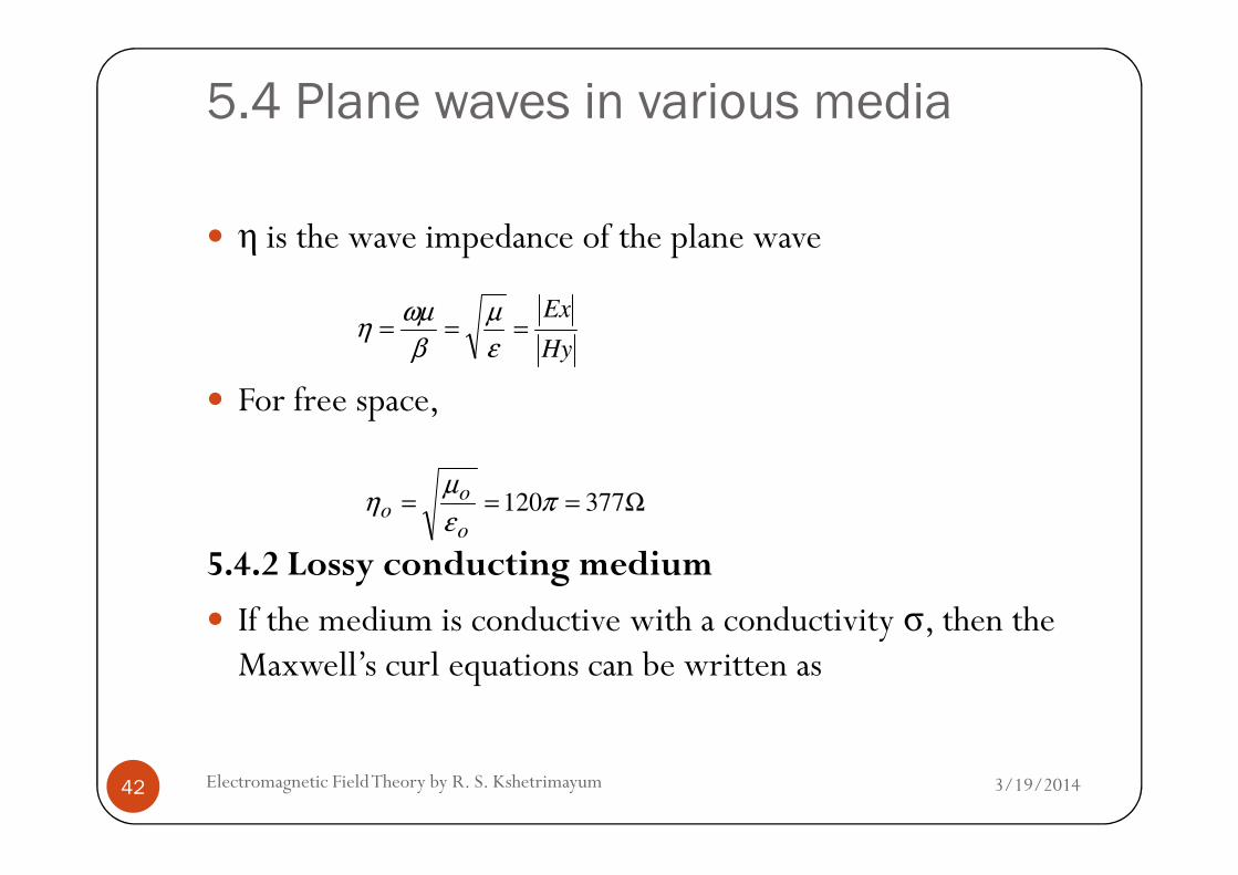
η is the wave impedance of the plane wave
For free space,
Hy
Ex===
ε
µ
β
ωµη
3/19/2014Electromagnetic Field Theory by R. S. Kshetrimayum42
5.4.2 Lossy conducting medium
If the medium is conductive with a conductivity σ, then the Maxwell’s curl equations can be written as
Ω=== 377120πε
µη
o
oo

5.4 Plane waves in various media
;E j Hωµ∇× = −r r
( ) ;effH j E E j E j Eω ε σ ω ε σ ω ε∇ × = + = + =r r r r r
3/19/2014Electromagnetic Field Theory by R. S. Kshetrimayum43
The effect of the conductivity has been absorbed in the complex frequency dependent effective permittivity
( ) 1eff
j j
j
σ σ σε ω ε ε ε
ω ω ωε
= + = − = −

5.4 Plane waves in various media
We can define a complex propagation constant
( ) ( )22 2 2
0eff
E E E j Eω µε ω γ⇒∇ + = ∇ + =r r r r
( )effj jγ ω µε ω α β= = +
3/19/2014Electromagnetic Field Theory by R. S. Kshetrimayum44
where α is the attenuation constant and β is the phase constant
( )effj jγ ω µε ω α β= = +

5.4 Plane waves in various media
What is implication of complex wave vector?
The wave is exponentially decaying (see example 4.4).
The dispersion relation for a conductor (usually non-magnetic) is
( )ε ω ω
3/19/2014Electromagnetic Field Theory by R. S. Kshetrimayum45
where neff is the complex refractive index
( )( )
( ) ( )0 0 0 0
0
eff
eff eff effj j j n j n
c
ε ω ωγ ω µε ω ω µ ε ω µ ε ω ω
ε= = = =

5.4 Plane waves in various media
1-D wave equation for general lossy medium becomes
whose solution is 1-D plane waves as follows
02
2
2
=−∂
∂x
x Ez
Eγ
3/19/2014Electromagnetic Field Theory by R. S. Kshetrimayum46
zjzzjzzzx eeEeeEeEeEzE
βαβαγγ −−−++−−+ +=+=)(
5.4 Plane waves in various media
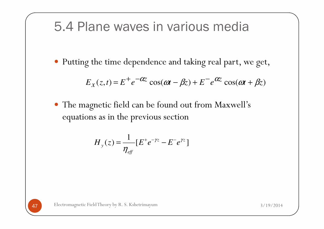
Putting the time dependence and taking real part, we get,
The magnetic field can be found out from Maxwell’s equations as in the previous section
)cos()cos(),( zteEzteEtzEzz
x βωβω αα ++−= −−+
3/19/2014Electromagnetic Field Theory by R. S. Kshetrimayum47
equations as in the previous section
1( ) [ ]
z z
y
eff
H z E e E eγ γ
η+ − −= −

5.4 Plane waves in various media
where useful expression for intrinsic impedance is
The electric field and magnetic field are no longer in phase as
( ) ( )0 0 0
0
eff
effeff
j j
j
ωµ ωµ µη
γ ε ωω µ ε ω= = =
3/19/2014Electromagnetic Field Theory by R. S. Kshetrimayum48
The electric field and magnetic field are no longer in phase as εeff is complex
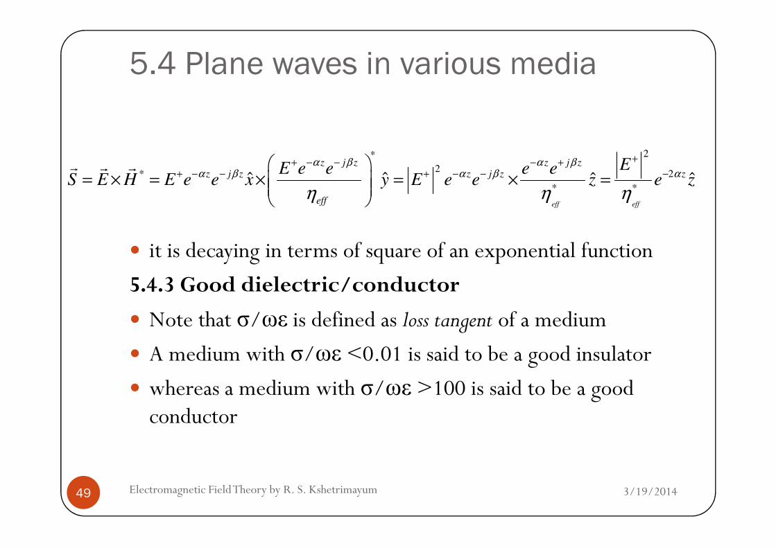
Poynting vector or power flow for this wave inside the lossyconducting medium is
5.4 Plane waves in various media
it is decaying in terms of square of an exponential function
5.4.3 Good dielectric/conductor
2*
2* 2
* *ˆ ˆ ˆ ˆ
eff eff
z j z z j zz j z z j z z
eff
EE e e e eS E H E e e x y E e e z e z
α β α βα β α β α
η η η
++ − − − ++ − − + − − −
= × = × = × =
r r r
3/19/2014Electromagnetic Field Theory by R. S. Kshetrimayum49
5.4.3 Good dielectric/conductor
Note that σ/ωε is defined as loss tangent of a medium
A medium with σ/ωε <0.01 is said to be a good insulator
whereas a medium with σ/ωε >100 is said to be a good conductor

5.4 Plane waves in various media
For good dielectric,
can be approximated using Taylor’s series expansion obtain αand β as follows:
( 1 )j
w jσ
σ ε γ ω µεωε
<< ∴ = −Q
ε
µσα
2= µεωβ =
3/19/2014Electromagnetic Field Theory by R. S. Kshetrimayum50
For a good conductor,
Therefore,
εα
2= µεωβ =
ωεσ >>
22)1(
µσβα
ωµσγ
wj ==⇒+≅

5.4 Plane waves in various media
Skin effect
The fields do attenuate as they travel in a good dielectric medium
α in a good dielectric is very small in comparison to that of a good conductor
3/19/2014Electromagnetic Field Theory by R. S. Kshetrimayum51
good conductor
As the amplitude of the wave varies with e-αz,
the wave amplitude reduces its value by 1/e or 37% times over a distance of
1δ
α=
1 2 2 1
2 f fβ ωµσ π µσ π µσ= = = =

5.4 Plane waves in various media
which is also known as skin depth
This means that in a good conductor (a) higher the frequency, lower is the skin depth
(b) higher is the conductivity, lower is the skin depth and
(c) higher is the permeability, lower is the skin depth
3/19/2014Electromagnetic Field Theory by R. S. Kshetrimayum52
(c) higher is the permeability, lower is the skin depth
Let us assume an EM wave which has x-component and traveling along the z-axis
Then, it can be expressed as
( ) ( )tzjz
x eeEtzEωβα −−−= 0,

5.4 Plane waves in various media
Taking the real part, we have,
Substituting the values of α and β for good conductors, we have,
( ) ( )zteEtzEz
x βωα −= −cos, 0
3/19/2014Electromagnetic Field Theory by R. S. Kshetrimayum53
have,
Now using the point form of Ohm’s law for conductors, we can write
( ) ( )zfteEtzEzf
x µσπωµσπ −= −cos,
0
( ) ( )zfteEtzEJzf
xx µσπωσσ µσπ −== −cos,
0

5.4 Plane waves in various media
What is the phase velocity and wavelength inside a good conductor?
2; 2
pv
ω πωδ λ πδ
β β= = = =
3/19/2014Electromagnetic Field Theory by R. S. Kshetrimayum54

5.5 SummaryElectromagnetic
Waves
Plane waves
PolarizationLossless
Good conductor
Plane waves in various media
Lossyconducting
Good dielectric
( ) ( ) tanx y z x y zk r k x k y k z xx yy zz k x k y k z con t• = + + • + + = + + =r r ) ) ) )) )
3/19/2014Electromagnetic Field Theory by R. S. Kshetrimayum55
Poynting vector
Lossless medium
conductor
Fig. 5.3 Plane waves in a nutshell
conducting medium
dielectric
ˆ ˆ( )j z
RHCP oE E x jy eβ−= −
r
∫∫∫∫ −∂
∂−
∂
∂−=•
VVVS
dvEdvEt
dvHt
sdS 222
2
1
2
1σεµ
rr
( ) ( ) ( )2 2
E H H H E E E Jt t
µ ε∂ ∂∴∇ • × = − • − • − •
∂ ∂
r r r r r r r r
µεωβ =
µεβ
ω 1==pv
ε
µ
β
ωµη ==
( )
−=
ωε
σεωε
jeff 1
( )effj jγ ω µε ω α β= = +
( )ωε
µ
γ
ωµη
eff
eff
j 00 ==
ε
µσα
2=
µεωβ =µσπβα
δf
111===
2
ωµσβα ==
2; 2
pv
ω πωδ λ πδ
β β= = = =
( ) ( )zfteEtzEJzf
xx µσπωσσ µσπ −== −cos, 0
( ) ( ) zj
yxLP eyExEzEβ−+= ˆˆ
00
r
( ) ( ) zjj
EP eyAexzEβφ −+= ˆˆ
r


