
5 Rib Metal Roofing System Ordering & Installation
Guide
Specifications contained herein subject to change without notice or obligation to make changes in products previously purchased.
2
5 Rib
Table of Contents
3-4 Basic Information 5 Delivery, Handling and Storage
5-10 Estimating and Ordering
11 New Roof Installation
12 Re-roof Installation
13 Fasteners
15 Flashing Details Overview
16 Eave Details
16-18 Valley and Gable Details
17 Ridge Details
17 Hip Details
18 Sidewall and Endwall Details
19 Gambrel Details
19 Pipe Flashings
20-21 Skylight Details
22 Chimney Details
23 Key Terms
3
5 RIB
INSTALLATION GUIDELINES
Caution: 5 Rib roofing panels must be applied on a minimum roof pitch of 2½:12 or greater. Important Notice: This guide must by read in its entirety before beginning installation. This guide is supplied by FABRAL, Inc. for use by its customers, and is intended to be a guide only. This does not replace local or state building codes. FABRAL, Inc. assumes no responsibility for any problems, which might arise as a result of improper installation or any personal injury or property damage that might occur with the products use. Under certain conditions, panels may show waviness commonly referred to as “oil canning.” This is a characteristic of roll forming. Such oil canning will not be accepted as cause for rejection. In areas of high snow or ice accumulations, snow guards, or snow blocks, may need to be added to the metal roof system to reduce or eliminate snow or ice from cascading from a higher roof and damaging lower roofs, roof valleys, gutters, or objects on the ground. Check with your installer and local building codes as to the need of snow blocks or guards in your area and design appropriately.
4
MINIMUM RECOMMENDED TOOLS & EQUIPMENT
Caulking Gun—Used for miscellaneous caulking and sealing to inhibit water infiltration. Chalk Line—Used to assist in the alignment of panels, flashings, etc. Electric Drill—Used to drill holes such as those required for pop rivet installation.
Electric Nibblers or Metal Shears—Used for general metal cutting, such as cutting the panels in hip and valley areas. Some installers prefer using a circular saw with a metal cutting abrasive blade. This method may be faster, but it has some drawbacks:
Saw cut edges are jagged and unsightly and tend to rust more quickly than sheared edges. Saw cutting produces hot metal filings that can embed in the paint and cause rust marks on the
face of the panel. Saw cutting burns the paint & galvanizing at the cut edge leading to the onset of edge rust.
Locking Pliers—Standard and “Duckbill” style for miscellaneous clamping and bending of parts. Marking Tools—Indelible markers, pencils, or scratching tools. Rivet Tool—Used for miscellaneous flashing and trim applications. Rubber Mallet – may be used to help snap panels together. Scratch Awl—Can be made from old screw drivers ground to a point. Used to mark the steel, open hems, and as a punch.
Screw Gun—2,000 to 2,500 rpm Clutch type screw gun with a depth sensing nose piece is recommended to ensure proper installation of the screws. The following bits will be required:
1/4” hex 5/16” hex #2 Combination Square/Phillips bit
Snips—For miscellaneous panel and flashing cutting requirements. Three pairs will be required: one for left edge, one for right edge, and one for centerline cuts. Tape Measure—25 foot minimum. Utility Knife—Used for miscellaneous cutting.
5
SAFETY CONSIDERATIONS
Never use unsecured or partially installed panels as a working platform. Do not walk on panels until they are in
place on the roof and all of the fasteners have been installed. Metal roofing panels are slippery when wet, dusty, frosty, or oily. Do not attempt to walk on a metal roof under
these conditions. Wearing soft-soled shoes will improve traction and minimize damage to the painted surface. Always be aware of your position on the roof relative to your surroundings. Take note of the locations of roof
openings, roof edges, equipment, co-workers, etc. Always wear proper clothing and safety attire. Wear proper clothing when working with sheet metal in order to
minimize the potential for cuts, abrasions and other injuries. Eye protection and gloves are a must when working with sheet metal products. Hearing protection should be used when power-cutting metal panels. When working on a roof, fall protection is highly recommended. Follow all OSHA Safety Requirements.
Use care when operating electrical and other power equipment. Observe all manufacturers’ safety recommendations.
Roof installation on windy days can be dangerous. Avoid working with sheet metal products on windy days.
DELIVERY, HANDLING & STORAGE
Always inspect the shipment upon delivery. Check for damage and verify material quantities against the shipping list. Note any damaged material or shortages at the time of delivery.
Handle panel bundles and individual panels with care to avoid damage. Longer bundles and panels may require two
or more “pick points” properly spaced to avoid damage that can result from buckling and/or bending of the panels.
Store the panels and other materials in a dry, well-ventilated area, away from traffic. Elevate one end of the bundle so that any moisture that may have accumulated during shipping can run off. Be sure that air will be able to circulate freely around the bundles to avoid the build-up of moisture, if possible, separate sheets to ensure moisture is not trapped between the sheets. Never store materials in direct contact with the ground.
Wear clean, non-marking, soft-soled shoes when walking on the panels to avoid shoe marks or damage to the finish.
Step only in the flat area of the panels.

6
ESTIMATING & ORDERING A ROOF
A. Sketch a birds-eye view of the roof and label each section (see example below.)
G
FH
ED
I
CB
A
B Sketch a diagram of each roof section. Show all measurements (see example below.) It is important to measure exact center of the ridge to the eave edge. Do not allow anything for overhang.
G
E
F
H
I
D
C
B
A
22'
6'
6'
12'8' 8'
8'23'
40'15'
14'
6'
8'
22'
16'
10'
18' 18'24'
10'
30'30'
15' 14'13' 15'
13'
10'
22'
15'14'
22'
15'
18'
10'
12'
18'15'
Additional Information Required: Roof Pitch, Skylights (Location & Size), Chimney (Location & Size), and Size and Number of Pipe Penetrations. Additional Identification: Ridge, Hips, Valleys, Gables, Etc.
Step 1

7
ESTIMATING & ORDERING A ROOF (cont.)
From the diagram you completed in Step 1, you are now ready to develop your roofing panel cut list. Each panel covers 36” of area so the only measurements you need are the distance from the eave to the ridge and the ridge length. You can then determine the number of panels needed by dividing the ridge length by the panel coverage. (See example Diagram A below.)
DIAGRAM A
25'
25'
12'
12'
EAVE
EAVE
RIDGE
GAB
LEG
ABLE
GAB
LEG
ABLE
Section A
Section B
The length from the eave to the ridge is 12’. The length of the ridge is 25’; therefore, the number of panels to complete one side of the house is 25 ÷ 3 = 9 pcs. Your materials list should look like Sample “B”.
SAMPLE B
Section A—9 pcs. X 12’
Now look at your roof diagram and figure out your next section of roof. Refer back to Diagram A. Section B of this sample roof is the same as Section A. Your materials list should now look like Sample C below.
SAMPLE C Section A—9 pcs. X 12’ Section B—9 pcs. X 12’
If your home has hips or valleys, refer to Diagram 1A below.
DIAGRAM 1A
10'
10'
40'
30'
20'
EAVE
Section B
RIDGE
Section A
EAVE
GAB
LEG
ABLE
EAVE
RID
GE
EAVE
GABLEGABLE
VALLEY
HIP
Step 2
8
ESTIMATING & ORDERING A ROOF (cont.)
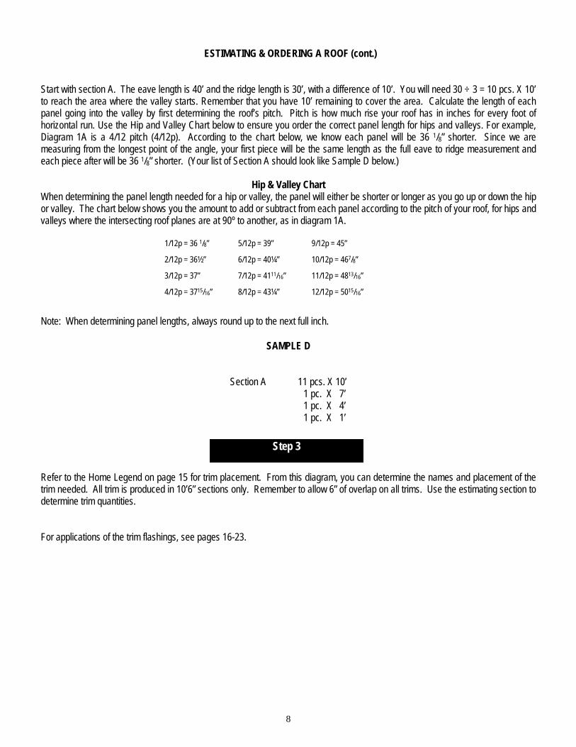
Start with section A. The eave length is 40’ and the ridge length is 30’, with a difference of 10’. You will need 30 ÷ 3 = 10 pcs. X 10’ to reach the area where the valley starts. Remember that you have 10’ remaining to cover the area. Calculate the length of each panel going into the valley by first determining the roof’s pitch. Pitch is how much rise your roof has in inches for every foot of horizontal run. Use the Hip and Valley Chart below to ensure you order the correct panel length for hips and valleys. For example, Diagram 1A is a 4/12 pitch (4/12p). According to the chart below, we know each panel will be 36 1/8” shorter. Since we are measuring from the longest point of the angle, your first piece will be the same length as the full eave to ridge measurement and each piece after will be 36 1/8” shorter. (Your list of Section A should look like Sample D below.)
Hip & Valley Chart When determining the panel length needed for a hip or valley, the panel will either be shorter or longer as you go up or down the hip or valley. The chart below shows you the amount to add or subtract from each panel according to the pitch of your roof, for hips and valleys where the intersecting roof planes are at 90º to another, as in diagram 1A.
1/12p = 36 1/8” 5/12p = 39” 9/12p = 45”
2/12p = 36½” 6/12p = 40¼” 10/12p = 467/8”
3/12p = 37” 7/12p = 4111/16” 11/12p = 4813/16”
4/12p = 3715/16” 8/12p = 43¼” 12/12p = 5015/16”
Note: When determining panel lengths, always round up to the next full inch.
SAMPLE D
Section A 11 pcs. X 10’ 1 pc. X 7’ 1 pc. X 4’ 1 pc. X 1’
Refer to the Home Legend on page 15 for trim placement. From this diagram, you can determine the names and placement of the trim needed. All trim is produced in 10’6” sections only. Remember to allow 6” of overlap on all trims. Use the estimating section to determine trim quantities. For applications of the trim flashings, see pages 16-23.Step 3 (Cont.)
Step 3

9
5 Rib Estimator/Order Guide
Accessories Determine the total lineal feet of each condition listed below and then fill that number in on each line. Use the equations on previous pages to calculate the number of pieces for each item and circle the flashing design required. Eave ___________
Ridge__________
Hip____________
Gable __________
Sidewall
Endwall__________
Valley__________ Transition _________
Gambrel _______
Skylight/Chimney width = ______
Eave: ft ÷ 10 = pcs. CE-1 EAVE Ridge: ft ÷ 10= pcs AR-3 OR RR-1 RIDGE CAP Note: For vented ridge use AR3 with Profile vent (below) or AR3 with Versavent attached Gable: ft ÷ 10 = pcs RG-1 OR WG-1 GABLE TRIM Sidewall and Endwall: (____ ft. sidewall + ____ ft. endwall) ÷ 10 = _____ pcs. ASW-1 TRIM Hip: _______ ft. ÷ 10 = _______ pcs. RR-1 RIDGE CAP Valley: ft ÷ 10 = pcs RV-1 OR RV-2 W-VALLEY Slope Transition: ft ÷10 = pcs AT-1 TRANSITION TRIM Gambrel: ft ÷ 10 = pcs AT-2 GAMBREL TRIM
FASTENER CALCULATIONS: Panel Screws: Quantity will vary based on spacing of fastener rows. For solid decking, use #14 x 1” MP screws. For 2 x 4 purlins, use #9 x 1” Woodfast screws Fastener Spacing Panel Screws per lineal foot of Roofing 12” 4.5 18” 3.0 24” 2.5
10
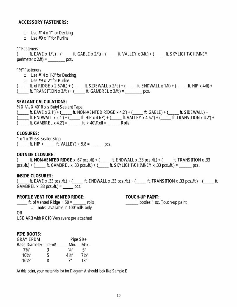
ACCESSORY FASTENERS: Use #14 x 1” for Decking Use #9 x 1” for Purlins
1” Fasteners (_____ ft. EAVE x 1/ft.) + (_____ ft. GABLE x 2/ft) + (_____ ft. VALLEY x 3/ft.) + (_____ ft. SKYLIGHT/CHIMNEY perimeter x 2/ft) = ________ pcs. 1½” Fasteners
Use #14 x 1½” for Decking Use #9 x 2” for Purlins
(_____ ft. of RIDGE x 2.67/ft.) + (_____ ft. SIDEWALL x 2/ft.) + (_____ ft. ENDWALL x 1/ft) + (_____ ft. HIP x 4/ft) + (_____ ft. TRANSITION x 3/ft.) + (_____ ft. GAMBREL x 3/ft.) = ________ pcs. SEALANT CALCULATIONS: ¼ X 3/16 X 40’ Rolls Butyl Sealant Tape (_____ ft. EAVE x 2.1’) + (_____ ft. NON-VENTED RIDGE x 4.2’) + (_____ ft. GABLE) + (_____ ft. SIDEWALL) + (_____ ft. ENDWALL x 2.1’) + (_____ ft. HIP x 4.67’) + (_____ ft. VALLEY x 4.67’) + (_____ ft. TRANSITION x 4.2’) + (_____ ft. GAMBREL x 4.2’) = ______ ft. ÷ 40’/Roll = ______ Rolls CLOSURES: 1 x 1 x 19.68’ Sealer Strip (_____ ft. HIP + _____ ft. VALLEY) ÷ 9.8 = ______ pcs. OUTSIDE CLOSURE: (_____ ft. NON-VENTED RIDGE x .67 pcs./ft) + (_____ ft. ENDWALL x .33 pcs./ft.) + (_____ft. TRANSITION x .33 pcs./ft.) + (_____ ft. GAMBREL x .33 pcs./ft.) + (_____ ft. SKYLIGHT/CHIMNEY x .33 pcs./ft.) = ______ pcs. INSIDE CLOSURES: (_____ ft. EAVE x .33 pcs./ft.) + (_____ ft. ENDWALL x .33 pcs./ft.) + (_____ ft. TRANSITION x .33 pcs./ft.) + (_____ ft. GAMBREL x .33 pcs./ft.) = _____ pcs. PROFILE VENT FOR VENTED RIDGE: _____ ft. of Vented Ridge ÷ 50 = ______ rolls
note: available in 100’ rolls only OR USE AR3 with RX10 Versavent pre attached PIPE BOOTS: GRAY EPDM Pipe Size Base Diameter Item# Min. Max. 7¾” 3 ¼” 5” 10¾” 5 4¼” 7½” 16½” 8 7” 13”
TOUCH-UP PAINT: ______ bottles 1 oz. Touch-up paint
At this point, your materials list for Diagram A should look like Sample E.

11
SAMPLE E
Panels: Section A 9 pcs. X 12’ Section B 9 pcs. X 12’
Trim: 6 pcs. CE-1 Eave Trim 5/12p 3 pcs. RR-1 Ridge Cap 5/12p 6 pcs. WG-1 Gable Trim 700 pcs. #14 x 1” Panel Screws 200 pcs. #14 x 1” Trim Screws 100 pcs. #14 x 1.5” Trim Screws 4 Rolls Butyl Sealant Tape 17 pcs. Inside Closure 1 Roll (100’) Profile Vent GR3/AT 1 pc. #3 Pipe Boot
You are now ready to order your new metal roof. If you have any questions, or need you materials list checked, please contact your local FABRAL Distributor.
5 Rib® Order Form
Panels: Color = ___________ ______ pcs. @ ______ ft. ______ in. ______ pcs. @ ______ ft. ______ in. ______ pcs. @ ______ ft. ______ in. ______ pcs. @ ______ ft. ______ in. ______ pcs. @ ______ ft. ______ in. ______ pcs. @ ______ ft. ______ in. ______ pcs. @ ______ ft. ______ in.
Accessories: ______ pcs. of Eave Flash ______ (flashing code) ______ pcs. of Ridge Flash ______ ______ pcs. of Gable Flash ______ ______ pcs. of Sidewall Flash ______ ______ pcs. of Endwall Flash ______ ______ pcs. of Valley Flash ______ ______ pcs. of Transition Flash ______ ______ pcs. of Gambrel Flash ______ ______ pcs. of Peak Flash ______ ______ pcs. of J Channel ______
______ pcs. of #14 x 1” or 1½” MP Painted Screws ______ pcs. of Tube Caulk ______ pcs. of Butyl Sealant Tape ______ pcs. 1 x 1 x 13.2’ Sealer Strip
12
NEW ROOFS
1. Make sure there are no nails or other objects protruding from the substrate that might puncture the underlayment or damage the roof panels. Clean all debris from the deck. Check for any high or low spots in the deck, which will cause waviness in the metal panels.
2. Check all details for possible roof penetrations, which must be added to the deck prior to roof panel installation (vented ridge for
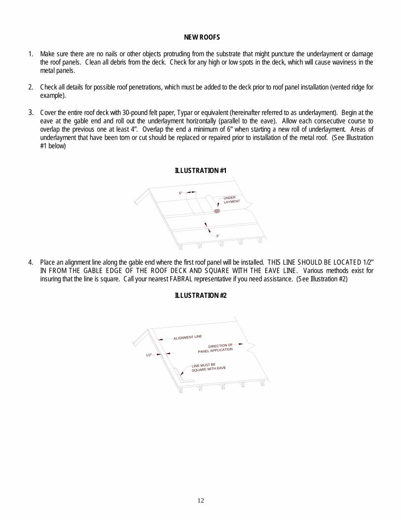
example). 3. Cover the entire roof deck with 30-pound felt paper, Typar or equivalent (hereinafter referred to as underlayment). Begin at the
eave at the gable end and roll out the underlayment horizontally (parallel to the eave). Allow each consecutive course to overlap the previous one at least 4”. Overlap the end a minimum of 6” when starting a new roll of underlayment. Areas of underlayment that have been torn or cut should be replaced or repaired prior to installation of the metal roof. (See Illustration #1 below)
ILLUSTRATION #1
UNDER
LAYMENT
6"
3"
4. Place an alignment line along the gable end where the first roof panel will be installed. THIS LINE SHOULD BE LOCATED 1/2”
IN FROM THE GABLE EDGE OF THE ROOF DECK AND SQUARE WITH THE EAVE LINE. Various methods exist for insuring that the line is square. Call your nearest FABRAL representative if you need assistance. (See Illustration #2)
ILLUSTRATION #2
1/2"
ALIGNMENT LINE
LINE MUST BE
SQUARE WITH EAVE
DIRECTION OF
PANEL APPLICATION

13
EXISTING ROOFS
In many cases, FABRAL’s Steel Roofing Panels can be installed over existing roofing without tear-off of the old roofing. Check with your local codes or building department for the specific requirements in your area. If the roof is to be stripped down to the existing decking, follow the procedures for new roofs on page 12. Be sure to check the existing roof and repair any damaged areas prior to installation of the new roof system. The following steps should be taken when installing new metal roof panels over existing roofing. 1. Inspect the roof for damage and make the necessary repairs. 2. Secure any warped or loose roofing. 3. Make sure there are no nails or other objects protruding from the roof that might puncture the new underlayment or
damage the new roof panels. 4. Remove all moss and other debris from the roof. 5. Cut off any overhanging roofing flush with the roof deck, and remove all hip and ridge caps. 6. Install 2x4 Purlins @ 24” o.c. to attach the panels or follow the directions on page 12, #2 through #4, on roof preparation. Note: For best results, Metal Roofing requires a relatively smooth and flat substrate. Application over rough and/or uneven surfaces is not recommended.
PANEL INSTALLATION
Note: Prior to panel installation, determine which items need to be installed prior to panels (such as eave, valley, swept wing, etc.)
1. Working off the eave edge, establish a straight line up the gable edge from which you are starting. This will insure that the first panel laid will be straight and square with the eave. (See Illustration #2 on page 12)
2. Before fastening the panel to the roof deck, check to make sure that the panel is overhanging the eave by 1”.
3. Once the first panel is in proper position, secure it to the roof deck with #14 fasteners per the standard fastening pattern.
4. Set the gable trim into a bead of butyl tape and screw it to the fascia board (see pages 16-17). This fully secures the first panel to the roof deck.
5. Position the second panel (overlap edge on top of the underlap edge of first panel) assuring that the eave edge is in position (1” overhang). Secure the second panel to the deck with #14 fasteners.
6. Each consecutive panel will be installed in the same manner.

14
5 RIB®
FASTENERS
Note the diagram below for proper installation of gasketed fasteners.
PROPER INSTALLATION OF GASKETED FASTENERS
correctly driven under-driven over-driven
Load Span Tables for 29 ga. 5 Rib
ALLOWABLE LIVE LOAD (psf) for 29 ga. 80 ksi PANELS Purlin Or Nailer Spacing (ft.)
LOAD SPAN TABLE FOR 29 GA. 5 RIB ALLOWABLE WIND UPLIFT LOADS (psf)
*Maximum 24” spacing
E a v e s a n d E n d la p s - R o o f P u rlin s
In te rm e d ia te R o o f P u r lin s a n d A ll S id in g
Listed above are the fasteners recommended for the proper installation of the Metal panels.
Fasteners Description Use
#9 x 1" Woodfast
Roof Panels attached to Purlins and Trim; Siding attached to wood girts
#14 x 1" Woodtite
Roof Panels attached to
OSB or Plywood and Trim; Siding attached to
plywood
#9 x 2" Woodfast
Attaching ridge cap and other trim through the top of the rib with 1x or
2x material
#14 x 2" Woodfast
Attaching ridge cap and other trim through the top of the rib with OSB
or plywood
Spans 1.0 1.5 2.0 2.5 3.0 3 OR
MORE Load (psf)
450 200 112 72 50
Substrate Fastener 9” 12” 15” 18” 21” 24”
¾” Plywood #14 x 1” MP 275.6 206.7 165.4 137.8 118.1 103.4
5/8” Plywood #14 x 1” MP 160 120 96 80 68.6 60
½” Plywood #14 x 1” MP 135.9 101.9 81.5 67.9 58.2 51
7/16” OSB #14 x 1” MP 61.5 46.1 36.9 30.7 26.3 23.1
19/32” OSB #14 x 1” MP 100.7 75.5 60.4 50.3 43.1 37.8
23/32” OSB #14 x 1” MP 115.9 86.9 69.5 57.9 49.7 43.5
Solid 2x SPF #9 x 1” WF 218.7 164.0 131.2 109.3 93.7 82
Solid 1x Pine #9 x 1” WF 168.4 126.3 101 84.2 72.2 63.2
Screws per Sq. 190 150 120 100 90 80
Note: Live loads are based on panel load capacity only and do not apply to load capacity of trusses, purlins, or decking.

15
5 RIB INSTALLATION GUIDE
ENDWA LL
GABLE/RAKE
E AVE
PIPE PENETRATION
VALLEY
RIDGE/P EAK
SIDEWA LL
GABLE/RAKE
HIP
MONOSLOPE RIDGE CP-1
DENVER EAVE CE-1
RESIDENTIAL GABLE WG-1
RESIDENTIAL GABLE RG-1
SIDEWALL/ENDWALL FLASH
ASW-1
GAMBREL AT-2
RIDGE AR-3
TRANSITION FLASH AT-1
VALLEY RV-1
VALLEY RV-2
RESIDENTIAL RIDGE/HIP FLASH RR-1

16
EAVE DETAIL
FASTENER @ 12" C/C
CE-1
FASTENER
BUTYL TAPE TOP & BOTTOM OF CLOSURE
ROOF STRUCTURE
29 GA. AGRI PANEL
INSIDE CLOSURE
Notes: 1. Roofing underlayment not shown. 2. Tack the eave flashing in place under the underlayment
using roofing nails. 3. Install the panels and closures as shown, allowing ½” to
1” of hang at eave.
VALLEY DETAIL
CUT PANEL AS NECESSARY 4" MINIMUM
29 GA. AGRI PANEL
SEALER STRIP,1"x1"x13'BLOCK CLOSUREFILLS RIB VOIDS
ROOF FELT ANDICE & WATER SHIELD
ROOF STRUCTURE PLYWOOD OR
SOLID SUPPORT
SCREWS EACH SIDE OF MAIN
RIB (EAVE/ENDLAP PATTERN) AND
ONE ADDITIONAL, CENTRALLY LOCATED
IN THE PAN OF THE PANEL.
RV-1 OR RV-2 (SHOWN)
BUTYL SEALANT TOP & BOTTOM OF SEALER STRIP
Notes: 1. Roofing underlayment not shown. 2. Place a second layer of 36” roofing underlayment in the
centerline of the valley with 18” of underlayment on each side of the valley.
3. When valley flashing is overlapped, 6” of lap is recommended with sealant applied under the lap.
4. Install sealant and 1 x 1 x 19’ sealer strip as shown. 5. Field cut the roofing panels holding back 4”-6” from
valley as shown. 6. Fasten the panels through the valley flashing as shown
with fasteners on both sides of each main rib. In applications with extreme angles, an additional fastener may be needed between ribs.
START GABLE DETAIL
ROOF STRUCTURE
29 GA. AGRI PANEL
RG-1, ORWG-1
SCREWFASTENER
@ 12" C/C
BUTYL TAPE
FINISH GABLE DETAIL
CUT PANEL AS NECESSARY BUTYL TAPE
29 GA. AGRI PANEL
RG-1, ORWG-1
SCREWFASTENER@ 12" C/C
ROOF STRUCTURE
Notes: 1. Roofing underlayment not shown. 2. Install the gable trim by placing it over the edge of the
roof as shown and fasten it to the fascia board at 12” on center.
3. The eave end of the gable-trim can be closed-off by snipping and folding.
4. For gable detail at ridge, see page 17. 5. When the last roof panel extends past the roof, trim
panel and finish as shown.

17
RIDGE & GABLE DETAILS
GABLE TRIM
SEALANT IS USED BETWEENRIDGE & GABLE ANDUNDER GABLE LAP
FASTENER
RIDGE
RIDGE DETAIL
ROOF STRUCTURE
FASTENER 9" C/C MAX#14 x 1 1/2" LONG
TOP & BOTTOM OFSEALANT TAPE
29 GA. AGRI PANEL
RR-1 or AR-3RIDGE CAP
OUTSIDE CLOSURE
VENTED RIDGE
Note: RX10 Versavent can be used instead of Profilevent (shown)
#14 x 1 1/2" LONG FASTENER9" C/C MAX
29 GA. AGRI PANEL
ROOF STRUCTURE
RIDGE CAPAR-3
PROFILE VENT
Notes:
1. Roofing underlayment not shown. 2. Plywood should be held back or cut back 1½” from each side of the ridge. 3. Attach the panels checking the 1” minimum overhang at the eave. 4. Mark edge of ridge cap on both sides of the peak. Unroll profile vent and press into place about 1” upslope of mark. 5. The gable flashing must be installed prior to the ridge installation. 6. Fasten the ridge cap using #14 x 1½” MP screws on each panel rib 1” back from the edge of the profile vent
HIP DETAIL
ROOF STRUCTURE
TOP & BOTTOM OF SEALANT TAPE
29 GA. AGRI PANEL
RR-1 or AR-3RIDGE CAP
STRIP SEALER
#14 x 1 1/2" LONG FASTENER 9" C/C MAX
HIP ROOF—PLAN VIEW
HIP CAP
29 GA. AGRI PANEL
Note: 1. Hip flashing attachment same as ridge (see detail above).

18
MONOSLOPE PEAK
2" LONG FASTENER AT EVERY RIB
(9" O.C.)
OUTSIDE CLOSURE
SEALANT TAPE TOP & BOTTOM OF
CLOSURE OR SEALER STRIP
30# ROOFING FELT
29 GA. ARGI PANEL
CP-1
ROOF STRUCTURE
Notes: 1. Roofing underlayment not shown. 2. Apply sealant to the bottom of the foam closure and
position it on the roof panel approximately ½” - 1” back from the edge of the flashing as shown.
3. Apply sealant to the top of the foam closure. 4. Install flashing as shown. 5. When more than one length of flashing is used, a 6”
minimum overlap is recommended. Apply sealant between the laps
ENDWALL DETAIL
BUTYL TAPE TOP & BOTTOM OF CLOSURE
OUTSIDE CLOSURE
FLASH ASW-1 29 GA. AGRI PANEL
FASTENER @ 9" C/C
Notes: 1. Roofing underlayment not shown. 2. Install the foam closure as shown using sealant on the
top and bottom. 3. Install endwall flashing as shown. 4. When more than one endwall is needed, a 6” minimum
overlap is recommended with sealant between the laps.
SIDEWALL DETAIL
ROOF SHEATHING
INSIDE CLOSURE
BUTYL SEALANT TOP OF BOTTOM
OF CLOSURE
FASTENER
29 GA. AGRI PANEL
ASW-1 FASTENER @ 9" C/C BUTYL SEALANT
Notes: 1. Roofing underlayment not shown. 2. The sidewall flashing is placed over the panel rib and
placed behind the siding as shown. 3. When the panel rib does not end up next to the wall, cut
the panel and bend a 1” return flange.
SWEPT WING GABLE
ROOF FELTBUTYL SEALANT TAPETOP & BOTTOM OFSEALER STRIP
SEALER STRIP(ASPHALT IMPREGNATED)
FASCIA BOARD
CE-1 FLASH
FASTENER
Note: 1. In high rain & snow areas, FABRAL recommends that a
high-grade underlayment, such as ice and water shield, be placed along the entire swept wing gable.
2. Roofing underlayment not shown. 3. Install the 1 x 1x 13’ sealer strip with a bead of butyl
sealant tape top and bottom. 4. Cut panels to fit the gable angle and align downslope
edge. 5. Fasten the panels through the flashing and into the deck
using #14 Mill Point screws per the standard eave fastening pattern.

19
GAMBREL DETAIL
ROOF PANEL
OUTSIDE CLOSURE
AT-2
BUTYL SEALANT TAPETOP & BOTTOMOF CLOSURE
FASTENER
BUTYL SEALANT TAPE TOP & BOTTOM
OF CLOSURE
INSIDE CLOSURE
FASTENER
ROOF STRUCTURE
Notes: 1. Roofing underlayment not shown. 2. Bottom panels of the slope transition must be
installed first. 3. Mark the location of the foam closure and place a bead
of butyl sealant tape on the panels. Install the closures and a second bead of sealant on top of the closures.
4. Install AT-1 Transition trim using #14 x 1½” MP screws into each rib of the bottom transition panels, 9” o.c.
5. Apply sealant as indicated.
SLOPE TRANSITION (WOOD FRAMING)
BUTYL TAPE TOP & BOTTOM OF CLOSURE
INSIDE CLOSUREFASTENER
@ 9" C/C
OUTSIDE CLOSURE
FLASH AT-1
29 GA. AGRI PANEL
PIPE FLASHING
VENTILATIONPIPE
29 GA. AGRI PANEL PIPE BOOT
BUTYL SEALANT TAPE UNDER BASE OF
PIPE BOOT
PLYWOOD DECK SCREWS SPACED 2" TO 3" MAXAROUND BASE TO SECURE
(OPTIONAL) SILICONE SEALANT AROUND
CUT OF BOOT
Notes: 1. Cut the hole in the flashing 20% smaller than the
pipe diameter. 2. Slide the flashing down the pipe. 3. Form the flashing to the roof profile. 4. Apply sealant around the perimeter of the flashing base
and fasten to roof using #14 x 1” fasteners.

20
CRICKET FIELD FORMED
FLANGE CAP2" MIN.
VE
RT
ICA
LUNIT
WIDTH
OVERALL HEIGHT TO BEMIDWAY PLUS ON HEAD
JAMB
VERTICALFLANGE2" MIN.
FLANGE CAP2" MIN.
2" MIN
2" MIN
BE
ND
2" MIN.
RIDGE
UNITHEIGHT
FLATSTOCK
Notes: 1. Trim both ends of the uphill and downhill sides of the
skylight flashing as indicated. 2. Slide the uphill flashing into the slots cut into the roofing
and apply a liberal amount of sealant. 3. Assemble the skylight as indicated on pages 20-21. 4. Trim and assemble chimney flashing similarly.
PROCEDURE FOR THE INSTALLATION OF SKYLIGHT FLASHING
C
C
CRICKET FIELDFORMED
B
A A
B
Notes: 1. Whenever possible, position the skylight curb so the ribs
of the roof panels do not interfere with the flashing. 2. Cut the roofing panels as close to the left, right and
downhill sides of the curb as possible. Cut the uphill side within 1” of the valley formed by the cricket.
3. The skylight flashings should be 4” wider than the width
of the curb (2” on each side). 4. Install with 1 x 1 sealer and sealant per Detail B-B on
page 21.

21
SKYLIGHT FLASHING PREPARATION
Detail A-A
ROOF FRAMING JAMB
ROOF SHEATHING
SEALANT
FASTENER SEALANT
FRAME SCREEN
SASH
FLASHING ASW-1 - FIELD MODIFYAS REQUIRED
29 GA. AGRI PANEL
ALTERNATE DETAIL A-A
ICE AND WATER SHIELD AND 30# FELT OR ROOFGUARD UNDERLAYMENT
CONTINUOUS SIKAFLEX CAULK @ PERIMETER
SEALANT TAPEBETWEEN FLASH AND ROOF PANEL
FLASHING -REVERSE AL FLASHING
SEALANT29 GA. AGRI PANEL
FASTENER @ 6" C/C
Notes: 1. Trim and bend the right side skylight flashing to fit as necessary. 2. Trim the left side in a similar fashion.
SKYLIGHT DETAIL B-B
5" MIN
SEALANT TAPETOP & BOTTOMOF CLOSURE
#10x1 1/2" WOODGRIPFASTENER6" O.C. MAX
ROOF SHEATHING
SASH
DRYWALL PLYWOOD
FRAME BATT INSULATION
INSIDE CLOSURE
SEALANT
1/2" PLYWOOD 1/2" RIGID INSULATION
29 GA. AGRI PANEL
CUSTOM DIVERTER FLASH CONTINUE SUCH THAT THE DIVERTER AND VALLEY FLASH OVERLAP
SKYLIGHT FLASHING (SIDE) DETAIL C-C
OUTSIDE CLOSURE HEADER ROOF SHEATHING
FASTENER
FRAME
SEALANT
SASH
29 GA. AGRI PANEL
#10 x 2" WOODGRIP FASTENER 9" O.C.
ASW-1 FLASHING FIELD MODIFIED
TO FIT
BUTYL TAPETOP & BOTTOM
OF CLOSURE

22
CHIMNEY FLASHING
CRICKET FIELDMADE FROMFLAT SHEET
ENDWALL FLASH
SIDEWALL FLASH
Notes: 1. Procedures for the installation of Chimney Flashings are
similar to the Skylight’s (refer to pages 20-21). 2. The saw-cut reglet shown provides the best weathertight
installation for chimneys. Fill the reglet with sealant, insert trim and fasten as necessary w/masonry anchors.
3. Flashings may be field-formed from 40 13/16” x 10’ flat sheets.
CHIMNEY FLASHING (SIDE)
ALTERNATE FLASHING
SEALANT TAPE BETWEEN FLASH AND ROOF PANEL
ROOF SHEATING
SEALANT
AL FLASHING
SAW CUT REGLET 1/2" - 1" DEEP BLOW OUT DUST & FILL WITH SIKAFLEXSEALANT. SET FLASH & FASTEN WITH COMPATIBLE MASONRY ANCHOR
CONTINUOUS SIKAFLEX CAULK @ PERIMETER
FLASHING -REVERSE AL FLASHING
29 GA. AGRI PANEL FASTENER @ 6" C/C
ICE AND WATER SHIELD AND30# FELT OR ROOFGUARD UNDERLAYMENT
CHIMNEY FLASHING (UPHILL SIDE)
SEALANT
ALTERNATE FLASHING
ROOF SHEATING
29 GA. AGRI PANEL
AL FLASHING
FASTENER SEALANT
FLASHING ASW-1 - FIELD MODIFYAS REQUIRED
SAW CUT REGLET 1/2" - 1" DEEP BLOW OUT DUST & FILL WITH SIKAFLEXSET FLASH & FASTEN WITH COMPATIBLEMASONRY ANCHOR
CHIMNEY FLASHING (DOWNHILL SIDE)
ROOF SHEATING #10x1 1/2" WOODGRIP FASTENER 6" O.C. MAX
BATT INSULATION SAW CUT REGLET 1/2" - 1" DEEP BLOW OUT DUST & FILL WITH SIKAFLEX SET FLASH & FASTEN WITH COMPATIBLE MASONRY ANCHOR
29 GA. AGRI PANEL
INSIDE CLOSURE
SEALANT TAPETOP & BOTTOMOF CLOSURE
5" MIN
1/2" PLYWOOD 1/2" RIGID INSULATION
CUSTOM DIVERTER FLASH CONTINUE SUCH THAT THE DIVERTER AND VALLEY FLASH OVERLAP
CHIMNEY (ALTERNATE SIDE)
SEALANT
AL FLASHING FASTENER
ALTERNATE FLASHING
OUTSIDE COLSURE
ROOF SHEATHING
ASW-1 FLASHINGFIELD MODIFIED
TO FIT #10 x 2" WOODGRIP
FASTENER 9" O.C.
BUTYL TAPETOP & BOTTOM
OF CLOSURE
29 GA. AGRI PANEL
SAW CUT REGLET 1/2" - 1" DEEP
BLOW OUT DUST & FILL WITH SIKAFLEX SET FLASH & FASTEN WITH COMPATIBLE
MASONRY ANCHOR
23
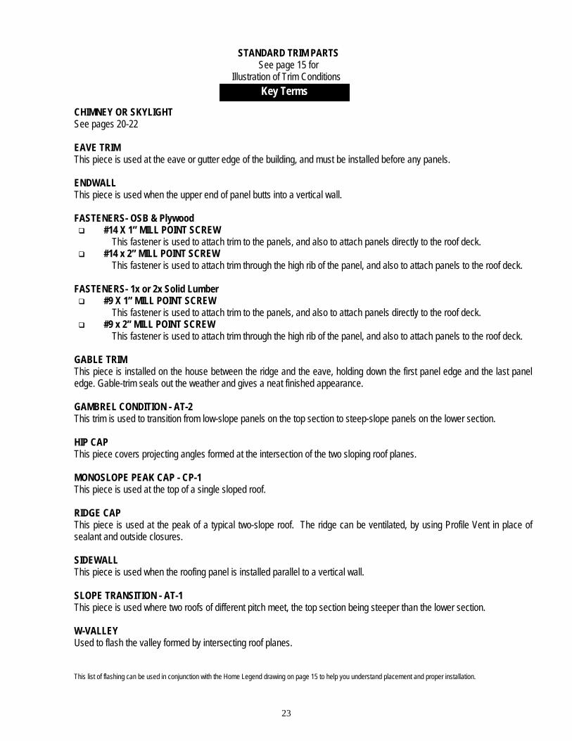
STANDARD TRIM PARTS See page 15 for
Illustration of Trim Conditions
CHIMNEY OR SKYLIGHT See pages 20-22 EAVE TRIM This piece is used at the eave or gutter edge of the building, and must be installed before any panels. ENDWALL This piece is used when the upper end of panel butts into a vertical wall. FASTENERS- OSB & Plywood #14 X 1” MILL POINT SCREW
This fastener is used to attach trim to the panels, and also to attach panels directly to the roof deck. #14 x 2” MILL POINT SCREW
This fastener is used to attach trim through the high rib of the panel, and also to attach panels to the roof deck.
FASTENERS- 1x or 2x Solid Lumber #9 X 1” MILL POINT SCREW
This fastener is used to attach trim to the panels, and also to attach panels directly to the roof deck. #9 x 2” MILL POINT SCREW
This fastener is used to attach trim through the high rib of the panel, and also to attach panels to the roof deck.
GABLE TRIM This piece is installed on the house between the ridge and the eave, holding down the first panel edge and the last panel edge. Gable-trim seals out the weather and gives a neat finished appearance. GAMBREL CONDITION - AT-2 This trim is used to transition from low-slope panels on the top section to steep-slope panels on the lower section. HIP CAP This piece covers projecting angles formed at the intersection of the two sloping roof planes. MONOSLOPE PEAK CAP - CP-1 This piece is used at the top of a single sloped roof. RIDGE CAP This piece is used at the peak of a typical two-slope roof. The ridge can be ventilated, by using Profile Vent in place of sealant and outside closures. SIDEWALL This piece is used when the roofing panel is installed parallel to a vertical wall. SLOPE TRANSITION - AT-1 This piece is used where two roofs of different pitch meet, the top section being steeper than the lower section. W-VALLEY Used to flash the valley formed by intersecting roof planes. This list of flashing can be used in conjunction with the Home Legend drawing on page 15 to help you understand placement and proper installation.
Key Terms
24
Headquarters: Lancaster Plant:
3449 Hempland Road Lancaster, PA 17601
(800)477-2741 Fax (800)283-4289
Other Manufacturing Facilities: Gridley Plant: Rt. 24 West
Gridley, IL 61744 (800)451-3974 Fax (800)289-3383
Jackson Plant:
308 Alabama Blvd. Jackson, GA 30233
(800)884-4484 Fax (800)765-4484
Tifton Plant: Hwy 41 South & 55 Lamp Loop
Tifton, GA 31793 (800)749-8144 Fax (800)380-4784
Idabel Plant:
Rt. 3 Box 632 Idabel, OK 74745
(800)926-8509 Fax (800)289-6007
Cedar City Plant: 2402 Industry Way
Cedar City, UT 84720 (800)432-2725 Fax (800)632-2725
Salem Plant:
4570 Ridge Drive, N.E. Salem, OR 97303
(800)477-9124 Fax (503)393-5813
Saint Joseph Plant: 600 15th Avenue N.E.
Saint Joseph, MN 56374 (800) 873-3440 Fax (320) 363-0553
LOW-21 © 2011 FABRAL (98-32-725) 10/11


