INSTALLATION INSTRUCTIONS
62-0287—03
Spyder® Lon Programmable, VAV/Unitary Controllers
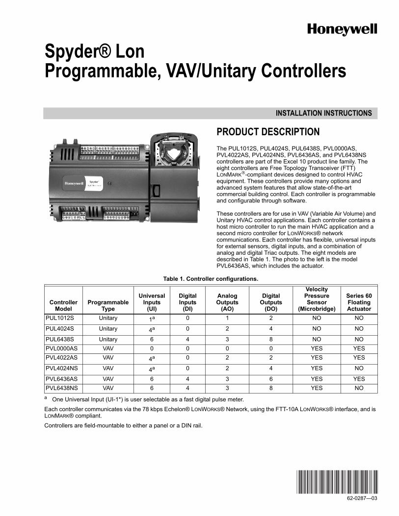
PRODUCT DESCRIPTIONThe PUL1012S, PUL4024S, PUL6438S, PVL0000AS, PVL4022AS, PVL4024NS, PVL6436AS, and PVL6438NS controllers are part of the Excel 10 product line family. The eight controllers are Free Topology Transceiver (FTT) LONMARK®-compliant devices designed to control HVAC equipment. These controllers provide many options and advanced system features that allow state-of-the-art commercial building control. Each controller is programmable and configurable through software.
These controllers are for use in VAV (Variable Air Volume) and Unitary HVAC control applications. Each controller contains a host micro controller to run the main HVAC application and a second micro controller for LONWORKS® network communications. Each controller has flexible, universal inputs for external sensors, digital inputs, and a combination of analog and digital Triac outputs. The eight models are described in Table 1. The photo to the left is the model PVL6436AS, which includes the actuator.
Table 1. Controller configurations.
a One Universal Input (UI-1*) is user selectable as a fast digital pulse meter.
Each controller communicates via the 78 kbps Echelon® LONWORKS® Network, using the FTT-10A LONWORKS® interface, and is LONMARK® compliant.
Controllers are field-mountable to either a panel or a DIN rail.
ControllerModel
ProgrammableType
UniversalInputs
(UI)
DigitalInputs
(DI)
AnalogOutputs
(AO)
DigitalOutputs
(DO)
VelocityPressureSensor
(Microbridge)
Series 60FloatingActuator
PUL1012S Unitary 1a 0 1 2 NO NO
PUL4024S Unitary 4a 0 2 4 NO NO
PUL6438S Unitary 6 4 3 8 NO NOPVL0000AS VAV 0 0 0 0 YES YESPVL4022AS VAV 4a 0 2 2 YES YES
PVL4024NS VAV 4a 0 2 4 YES NO
PVL6436AS VAV 6 4 3 6 YES YESPVL6438NS VAV 6 4 3 8 YES NO

SPYDER® LON PROGRAMMABLE, VAV/UNITARY CONTROLLERS
62-0287—03 2
SPECIFICATIONSGeneral SpecificationsRated Voltage: 20–30 Vac; 50/60 HzPower Consumption:
100 VA for controller and all connected loads (including the actuator on models PVL0000AS, PVL4022AS, and PVL6436AS)
Controller Only Load: 20 VA maximum; models PUL1012S, PUL4024S, PUL6438S, PVL4024NS, and PVL6438NS.
Controller and Actuator Load: 21 VA maximum; models PVL0000AS, PVL4022AS, and PVL6436AS
External Sensors Power Output: 20 Vdc ±10% @ 75 mA maximum
VAV Operating & Storage Temperature Ambient Rating (models PVL0000AS, PVL4022AS, PVL4024NS, PVL6436AS, and PVL6438NS):Minimum 32 F (0 C); Maximum 122 F (50 C)
Unitary Operating & Storage Temperature Ambient Rating (models PUL1012S, PUL4024S, and PUL6438S):Minimum -40 F (-40 C); Maximum 150 F (65.5 C)
Relative Humidity: 5% to 95% non-condensingLED: Provides status for normal operation, controller down-
load process, alarms, manual mode, and error conditions
BEFORE INSTALLATIONThe controller is available in eight models (see Table 1).
Review the power, input, and output specifications on page 2 before installing the controller.— Hardware driven by Triac outputs must have a minimum
current draw, when energized, of 25 mA and a maximum current draw of 500 mA.
— Hardware driven by the analog current outputs must have a maximum resistance of 550 Ohms, resulting in a maximum voltage of 11 volts when driven at 20 mA.If resistance exceeds 550 Ohms, voltages up to 18 Vdc are possible at the analog output terminal.
WARNINGElectrical Shock Hazard.Can cause severe injury, death or property damage.Disconnect power supply before beginning wiring or making wiring connections to prevent electrical shock or equipment damage.
INSTALLATIONThe controller must be mounted in a position that allows clearance for wiring, servicing, removal, connection of the LonWorks® Bus Jack, and access to the Neuron® Service Pin.
The controller may be mounted in any orientation.
IMPORTANTAvoid mounting in areas where acid fumes or other deteriorating vapors can attack the metal parts of the controller, or in areas where escaping gas or other explosive vapors are present. See Fig. 4–Fig. 7 on page 4 for mounting dimensions.
For PVL0000AS, PVL4022AS, and PVL6436AS models, the actuator is mounted first and then the controller is mounted. For the other models, go to “Mount Controller” on page 4 to begin the installation.
Mount Actuator onto Damper Shaft (PVL0000AS, PVL4022AS, and PVL6436AS)PVL0000AS, PVL4022AS, and PVL6436AS controllers include the direct-coupled actuator with Declutch mechanism, which is shipped hard-wired to the controller.
The actuator mounts directly onto the VAV box damper shaft and has up to 44 lb-in. (5 Nm) torque, 90-degree stroke, and 90 second timing at 60 Hz. The actuator is suitable for mounting onto a 3/8 to 1/2 in. (10 to 13 mm) square or round VAV box damper shaft. The minimum VAV box damper shaft length is 1-9/16 in. (40 mm).
The two mechanical end-limit set screws control the amount of rotation from 12° to 95°. These set screws must be securely fastened in place. To ensure tight closing of the damper, the shaft adapter has a total rotation stroke of 95° (see Fig. 1).
NOTE: The actuator is shipped with the mechanical end-limit set screws set to 95 degrees of rotation. Adjust the two set screws closer together to reduce the rotation travel. Each “hash mark” indicator on the bracket represents approximately 6.5° of rotation per side.
NOTE: The Declutch button, when pressed, allows you to rotate the universal shaft adapter (see Fig. 1).
IMPORTANTDetermine the damper rotation and opening angle prior to installation. See Fig. 2 and Fig. 3 on page 3 for examples.
Fig. 1. Series 60 Floating Actuator.
IMPORTANTMount actuator flush with damper housing or add a spacer between the actuator mounting surface and damper box housing.
UNIVERSAL SHAFT
CLAMPING BOLTS (2)
M23568
UNIVERSAL
SHAFT ADAPTER
MECHANICAL
END LIMIT SET
SCREWS (2)
DECLUTCH
BUTTON
SPYDER® LON PROGRAMMABLE, VAV/UNITARY CONTROLLERS
3 62-0287—03
Fig. 2. Damper with 90 degree CW rotation to open.
Before Mounting Actuator onto Damper Shaft (PVL0000AS, PVL4022AS, and PVL6436AS)
Tools required:— Phillips #2 screwdriver - end-limit set screw adjustment— 8 mm wrench - centering clamp
Before mounting the actuator onto the VAV box damper shaft, determine the following:
1. Determine the damper shaft diameter. It must be between 3/8 in. to 1/2 in. (10 to 13 mm).
2. Determine the length of the damper shaft. If the length of the VAV box damper shaft is less than 1-9/16 in. (40 mm), the actuator cannot be used.
3. Determine the direction the damper shaft rotates to open the damper (CW or CCW) (see Fig. 3). Typically, there is an etched line on the end of the damper shaft that indicates the position of the damper. In Fig. 2, the indicator shows the damper open in a CW direction.
4. Determine the damper full opening angle (45, 60, or 90 degrees). In Fig. 2, the damper is open to its full open position of 90 degrees.
Fig. 3. Determining the rotation direction (CW or CCW) for damper opening.
Mounting Actuator onto Damper Shaft (PVL0000AS, PVL4022AS, and PVL6436AS )The unit is shipped with the actuator set to rotate open in the clockwise (CW) direction to a full 95 degrees. The extra 5 degrees ensures a full opening range for a 90 degree damper. The installation procedure varies depending on the damper opening direction and angle:
1. If the damper rotates clockwise (CW) to open, and the angle of the damper open-to-closed is 90 degrees:a. Manually open the damper fully (rotate clockwise). b. Using the Declutch button, rotate the universal shaft
adapter fully clockwise. c. Mount the actuator to the VAV damper box and shaft. d. Tighten the two bolts on the centering clamp
(8 mm wrench; 70.8–88.5 lb-in. [8–10 Nm] torque). When the actuator closes, the damper rotates CCW 90 degrees to fully close.
2. If the damper rotates clockwise (CW) to open, and the angle of the damper open-to-closed is 45 or 60 degrees:a. Manually open the damper fully (rotate clockwise).b. The actuator is shipped with the mechanical
end-limits set at 95 degrees. Adjust the two mechanical end-limit set screws to provide the desired amount of rotation. Adjust the two set screws closer together to reduce the rotation travel.
c. Tighten the two mechanical end-limit screws (Phillips #2 screwdriver; (26.5–31 lb-in. [3.0–3.5 Nm] torque).
d. Using the Declutch button, rotate the universal shaft adapter fully clockwise.
e. Mount the actuator to the VAV damper box and shaft. f. Tighten the two bolts on the centering clamp
(8 mm wrench; 70.8–88.5 lb-in. [8–10 Nm] torque).g. When the actuator closes, the damper rotates CCW
either 45 or 60 degrees to fully close.3. If the damper rotates counterclockwise (CCW) to open,
and the angle of the damper open-to-closed is 90 degrees:a. Manually open the damper fully (rotate counter-
clockwise).b. Using the Declutch button, rotate the universal shaft
adapter fully counterclockwise. c. Mount the actuator to the damper box and shaft. d. Tighten the two bolts on the centering clamp (8 mm
wrench; 70.8–88.5 lb-in. [8–10 Nm] torque). When the actuator closes, the damper rotates CW 90 degrees to fully close.
4. If the damper rotates counterclockwise (CCW) to open, and the angle of the damper open-to-closed is 45 or 60 degrees:a. Manually open the damper fully (rotate counter-
clockwise).b. The actuator is shipped with the mechanical
end-limits set at 95 degrees. Adjust the two mechanical end-limit set screws to provide the desired amount of rotation. Adjust the two set screws closer together to reduce the rotation travel.
c. Tighten the two mechanical end-limit screws (Phillips #2 screwdriver; (26.5–31 lb-in. [3.0–3.5 Nm] torque).
d. Using the Declutch button, rotate the universal shaft adapter fully counter-clockwise.
e. Mount the actuator to the VAV damper box and shaft. f. Tighten the two bolts on the centering clamp
(8 mm wrench; 70.8–88.5 lb-in. [8–10 Nm] torque).g. When the actuator closes, the damper rotates CW
either 45 or 60 degrees to fully close.
M23569
DAMPER SHAFT
ROTATES
CLOCKWISE
TO OPEN
DAMPER
AIR
FLOW
AIR
FLOW
CW TO OPEN, CCW TO CLOSE
CCW TO OPEN, CW TO CLOSEM2067B
TYPE A DAMPER
TYPE B DAMPER
SPYDER® LON PROGRAMMABLE, VAV/UNITARY CONTROLLERS
62-0287—03 4
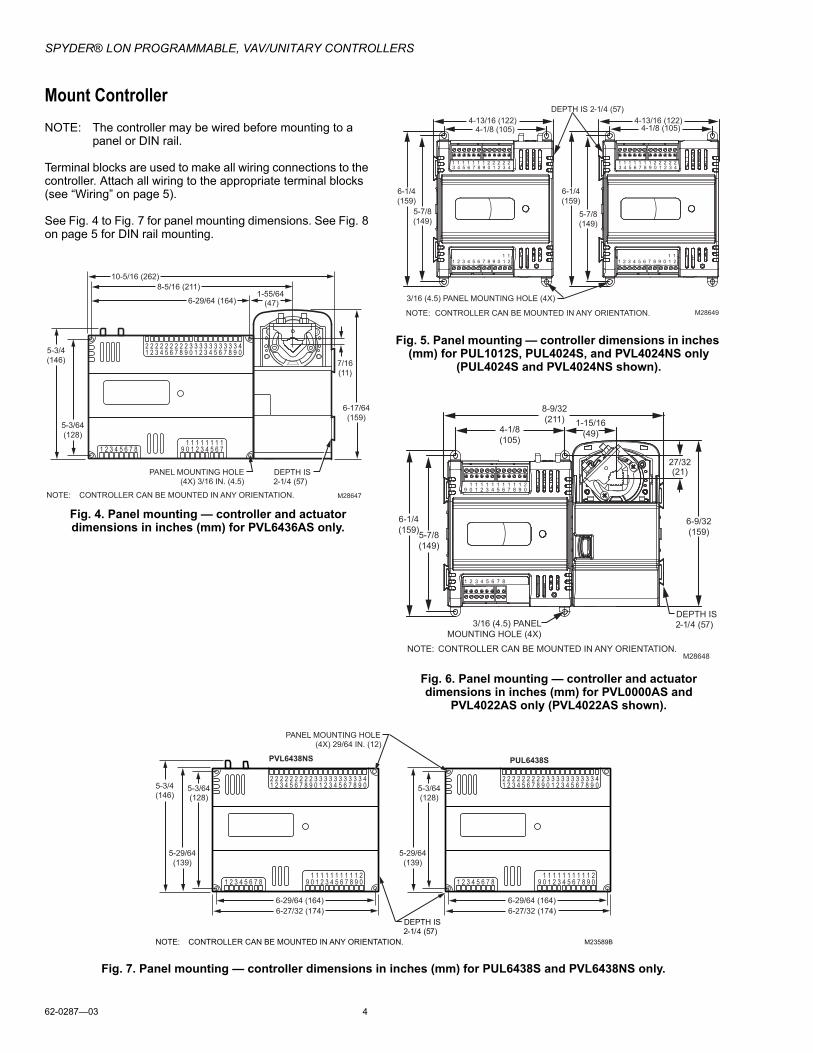
Mount ControllerNOTE: The controller may be wired before mounting to a
panel or DIN rail.
Terminal blocks are used to make all wiring connections to the controller. Attach all wiring to the appropriate terminal blocks (see “Wiring” on page 5).
See Fig. 4 to Fig. 7 for panel mounting dimensions. See Fig. 8 on page 5 for DIN rail mounting.
Fig. 4. Panel mounting — controller and actuator dimensions in inches (mm) for PVL6436AS only.
Fig. 5. Panel mounting — controller dimensions in inches (mm) for PUL1012S, PUL4024S, and PVL4024NS only
(PUL4024S and PVL4024NS shown).
Fig. 6. Panel mounting — controller and actuator dimensions in inches (mm) for PVL0000AS and
PVL4022AS only (PVL4022AS shown).
Fig. 7. Panel mounting — controller dimensions in inches (mm) for PUL6438S and PVL6438NS only.
1 2 3 4 5 6 7 8 109 2 3 4 5 6 711 1 1 1 1 1 1
1 2 3 4 5 6 7 8 0922 2 2 2 2 2 2 2 33
1 2 3 4 5 6 7 8 0933 33 33 33 4
5-3/4
(146)
10-5/16 (262)
NOTE: CONTROLLER CAN BE MOUNTED IN ANY ORIENTATION.
PANEL MOUNTING HOLE
(4X) 3/16 IN. (4.5)
M28647
5-3/64
(128)
8-5/16 (211)
6-29/64 (164)1-55/64
(47)
6-17/64
(159)
7/16
(11)
DEPTH IS
2-1/4 (57)
M28649NOTE: CONTROLLER CAN BE MOUNTED IN ANY ORIENTATION.
3/16 (4.5) PANEL MOUNTING HOLE (4X)
1 1 1 1 1 1 1 2 2 2 2 23 4 5 6 7 8 9 0 1 2 3 4
1 1 1 1 1 1 1 2 2 2 2 23 4 5 6 7 8 9 0 1 2 3 4
1 1
1 2 3 4 5 6 7 8 9 0 1 2
1 1
1 2 3 4 5 6 7 8 9 0 1 2
DEPTH IS 2-1/4 (57)
4-13/16 (122)
4-1/8 (105)
6-1/4
(159)
5-7/8
(149)
4-13/16 (122)4-1/8 (105)
6-1/4
(159)
5-7/8
(149)
NOTE: CONTROLLER CAN BE MOUNTED IN ANY ORIENTATION.M28648
8-9/32
(211) 1-15/16
(49)
6-9/32
(159)
3/16 (4.5) PANEL
MOUNTING HOLE (4X)
27/32(21)
4-1/8
(105)
6-1/4
(159)5-7/8
(149)
DEPTH IS
2-1/4 (57)
1 2 3 4 5 6 7 8
1 1 1 1 1 1 1 1 1 1 29 0 1 2 3 4 5 6 7 8 9 0
1 2 3 4 5 6 7 8 1 0 9 2 3 4 5 6 7 8 0 9 1 1 1 1 1 1 1 1 1 2 1
1 2 3 4 5 6 7 8 0 9 2 2 2 2 2 2 2 2 2 3 3
1 2 3 4 5 6 7 8 0 9 3 3 3 3 3 3 3 3 4
5-3/4
(146)
6-27/32 (174)
NOTE: CONTROLLER CAN BE MOUNTED IN ANY ORIENTATION.
PANEL MOUNTING HOLE
(4X) 29/64 IN. (12)
M23589B
5-3/64
(128)
6-29/64 (164)
5-29/64
(139)
1 2 3 4 5 6 7 8 1 0 9 2 3 4 5 6 7 8 0 9 1 1 1 1 1 1 1 1 1 2 1
1 2 3 4 5 6 7 8 0 9 2 2 2 2 2 2 2 2 2 3 3
1 2 3 4 5 6 7 8 0 9 3 3 3 3 3 3 3 3 4
6-27/32 (174)
5-3/64
(128)
6-29/64 (164)
5-29/64
(139)
PVL6438NS PUL6438S
DEPTH IS
2-1/4 (57)

SPYDER® LON PROGRAMMABLE, VAV/UNITARY CONTROLLERS
5 62-0287—03
Panel MountingThe controller enclosure is constructed of a plastic base plate and a plastic factory-snap-on cover.
NOTE: The controller is designed so that the cover does not need to be removed from the base plate for either mounting or wiring.
The controller mounts using four screws inserted through the corners of the base plate. Fasten securely with four No. 6 or No. 8 machine or sheet metal screws.
The controller can be mounted in any orientation. Ventilation openings are designed into the cover to allow proper heat dissipation, regardless of the mounting orientation.
DIN Rail Mounting (PUL1012S, PUL4024S, PUL6438S, PVL4024NS, and PVL6438NS)To mount the PUL1012S, PUL4024S, PUL6438S, PVL4024NS, or PVL6438NS controller on a DIN rail [standard EN50022; 1-3/8 in. x 9/32 in. (7.5 mm x 35 mm)], refer to Fig. 8 and perform the following steps:
1. Holding the controller with its top tilted in towards the DIN rail, hook the two top tabs on the back of the con-troller onto the top of the DIN rail.
2. Push down and in to snap the two bottom flex connec-tors of the controller onto the DIN rail.
Fig. 8. Controller DIN rail mounting (models PUL1012S, PUL4024S, PUL6438S, PVL4024NS, and PVL6438NS).
IMPORTANTTo remove the controller from the DIN rail, perform the following:1. Push straight up from the bottom to release the top
tabs.2. Rotate the top of the controller out towards you and
pull the controller down and away from the DIN rail to release the bottom flex connectors.
Piping (PVL0000AS, PVL4022AS, PVL4024NS, PVL6436AS, and PVL6438NS)Air flow PickupFor PVL0000AS, PVL4022AS, PVL4024NS, PVL6436AS, and PVL6438NS, connect the air flow pickup to the two restrictor ports on the controller (see Fig. 9).
NOTES:— Use 1/4 inch (6 mm) outside diameter, with a
0.040 in. (1 mm) wall thickness, plenum-rated 1219 FR (94V-2) tubing.
— Always use a fresh cut on the end of the tubing that connects to the air flow pickups and the restrictor ports on the controller.
Connect the high pressure or upstream tube to the plastic restrictor port labeled (+), and the low pressure or downstream tube to the restrictor port labeled (-). See labeling in Fig. 9. When twin tubing is used from the pickup, split the pickup tubing a short length to accommodate the connections.
NOTES:— If controllers are mounted in unusually dusty or
dirty environments, an inline, 5-micron disposable air filter (use 5-micron filters compatible with pneumatic controls) is recommended for the high pressure line (marked as +) connected to the air flow pickup.
— The tubing from the air flow pickup to the control-ler should not exceed three feet (0.914 m). Any length greater than this will degrade the flow sensing accuracy.
— Use caution when removing tubing from a con-nector. Always pull straight away from the con-nector or use diagonal cutters to cut the edge of the tubing attached to the connector. Never remove by pulling at an angle.
Fig. 9. Air flow pickup connections (PVL0000AS, PVL4022AS, PVL4024NS, PVL6436AS, and PVL6438NS).
WiringAll wiring must comply with applicable electrical codes and ordinances, or as specified on installation wiring diagrams. Controller wiring is terminated to the screw terminal blocks located on the top and the bottom of the device.
WARNINGElectrical Shock Hazard.Can cause severe injury, death or property damage.Disconnect power supply before beginning wiring or making wiring connections, to prevent electrical shock or equipment damage.
DIN RAIL
TOP TABS
BOTTOM FLEX
CONNECTORS M16815
M23556A
AIR FLOW
PICKUP
ΔP
1 2 3 4 5 6 7 8 1 0 9 2 3 4 5 6 7 8 0 9 1 1 1 1 1 1 1 1 1 2 1
1 2 3 4 5 6 7 8 0 9 2 2 2 2 2 2 2 2 2 3 3
1 2 3 4 5 6 7 8 0 9 3 3 3 3 3 3 3 3 4
RESTRICTOR
PORT RESTRICTOR
PORT
CONNECTOR
TUBING
SPYDER® LON PROGRAMMABLE, VAV/UNITARY CONTROLLERS
62-0287—03 6
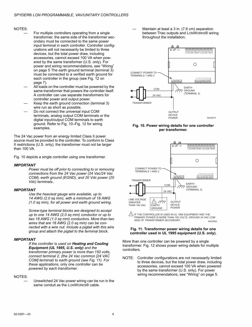
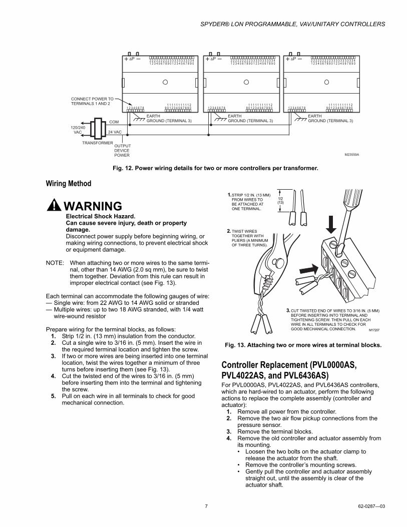
NOTES:— For multiple controllers operating from a single
transformer, the same side of the transformer sec-ondary must be connected to the same power input terminal in each controller. Controller config-urations will not necessarily be limited to three devices, but the total power draw, including accessories, cannot exceed 100 VA when pow-ered by the same transformer (U.S. only). For power and wiring recommendations, see “Wiring” on page 5 The earth ground terminal (terminal 3) must be connected to a verified earth ground for each controller in the group (see Fig. 12 on page 7).
— All loads on the controller must be powered by the same transformer that powers the controller itself. A controller can use separate transformers for controller power and output power.
— Keep the earth ground connection (terminal 3) wire run as short as possible.
— Do not connect the universal input COM terminals, analog output COM terminals or the digital input/output COM terminals to earth ground. Refer to Fig. 10–Fig. 12 for wiring examples.
The 24 Vac power from an energy limited Class II power source must be provided to the controller. To conform to Class II restrictions (U.S. only), the transformer must not be larger than 100 VA.
Fig. 10 depicts a single controller using one transformer.
IMPORTANTPower must be off prior to connecting to or removing connections from the 24 Vac power (24 Vac/24 Vac COM), earth ground (EGND), and 20 Vdc power (20 Vdc) terminals..
IMPORTANTUse the heaviest gauge wire available, up to 14 AWG (2.0 sq mm), with a minimum of 18 AWG (1.0 sq mm), for all power and earth ground wiring.
Screw-type terminal blocks are designed to accept up to one 14 AWG (2.0 sq mm) conductor or up to two 18 AWG (1.0 sq mm) conductors. More than two wires that are 18 AWG (2.0 sq mm) can be con-nected with a wire nut. Include a pigtail with this wire group and attach the pigtail to the terminal block.
IMPORTANTIf the controller is used on Heating and Cooling Equipment (UL 1995, U.S. only) and the transformer primary power is more than 150 volts, connect terminal 2, (the 24 Vac common [24 VAC COM] terminal) to earth ground (see Fig. 11). For these applications, only one controller can be powered by each transformer.
NOTES:— Unswitched 24 Vac power wiring can be run in the
same conduit as the LONWORKS® cable.
— Maintain at least a 3 in. (7.6 cm) separation between Triac outputs and LONWORKS® wiring throughout the installation.
Fig. 10. Power wiring details for one controller per transformer.
Fig. 11. Transformer power wiring details for one controller used in UL 1995 equipment (U.S. only).
More than one controller can be powered by a single transformer. Fig. 12 shows power wiring details for multiple controllers.
NOTE: Controller configurations are not necessarily limited to three devices, but the total power draw, including accessories, cannot exceed 100 VA when powered by the same transformer (U.S. only). For power wiring recommendations, see “Wiring” on page 5.
CONNECT POWER TO
TERMINALS 1 AND 2
EARTH
GROUND
(TERMINAL 3)
TRANSFORMER
OUTPUT
DEVICE
POWER M23557A
ΔP
1 2 3 4 5 6 7 8 1 0 9 2 3 4 5 6 7 8 0 9 1 1 1 1 1 1 1 1 1 2 1
1 2 3 4 5 6 7 8 0 9 2 2 2 2 2 2 2 2 2 3 3
1 2 3 4 5 6 7 8 0 9 3 3 3 3 3 3 3 3 4
COM
24 VAC
M23558A
EARTH
GROUND
(TERMINAL 3)
TRANSFORMER
OUTPUT
DEVICE
POWER
ΔP
1 2 3 4 5 6 7 8 1 0 9 2 3 4 5 6 7 8 0 9 1 1 1 1 1 1 1 1 1 2 1
1 2 3 4 5 6 7 8 0 9 2 2 2 2 2 2 2 2 2 3 3
1 2 3 4 5 6 7 8 0 9 3 3 3 3 3 3 3 3 4
EARTH
GROUND
1 LINE VOLTAGE
GREATER
THAN 150 VAC
IF THE CONTROLLER IS USED IN UL 1995 EQUIPMENT AND THE
PRIMARY POWER IS MORE THAN 150 VOLTS, GROUND 24 VAC COM
SIDE OF TRANSFORMER SECONDARY.
1
COM
24 VAC
CONNECT POWER TO
TERMINALS 1 AND 2
SPYDER® LON PROGRAMMABLE, VAV/UNITARY CONTROLLERS
7 62-0287—03
Fig. 12. Power wiring details for two or more controllers per transformer.
Wiring Method
WARNINGElectrical Shock Hazard.Can cause severe injury, death or property damage.Disconnect power supply before beginning wiring, or making wiring connections, to prevent electrical shock or equipment damage.
NOTE: When attaching two or more wires to the same termi-nal, other than 14 AWG (2.0 sq mm), be sure to twist them together. Deviation from this rule can result in improper electrical contact (see Fig. 13).
Each terminal can accommodate the following gauges of wire:— Single wire: from 22 AWG to 14 AWG solid or stranded— Multiple wires: up to two 18 AWG stranded, with 1/4 watt
wire-wound resistor
Prepare wiring for the terminal blocks, as follows:1. Strip 1/2 in. (13 mm) insulation from the conductor.2. Cut a single wire to 3/16 in. (5 mm). Insert the wire in
the required terminal location and tighten the screw.3. If two or more wires are being inserted into one terminal
location, twist the wires together a minimum of three turns before inserting them (see Fig. 13).
4. Cut the twisted end of the wires to 3/16 in. (5 mm) before inserting them into the terminal and tightening the screw.
5. Pull on each wire in all terminals to check for good mechanical connection.
Fig. 13. Attaching two or more wires at terminal blocks.
Controller Replacement (PVL0000AS, PVL4022AS, and PVL6436AS)For PVL0000AS, PVL4022AS, and PVL6436AS controllers, which are hard-wired to an actuator, perform the following actions to replace the complete assembly (controller and actuator):
1. Remove all power from the controller.2. Remove the two air flow pickup connections from the
pressure sensor.3. Remove the terminal blocks.4. Remove the old controller and actuator assembly from
its mounting.• Loosen the two bolts on the actuator clamp to
release the actuator from the shaft.• Remove the controller’s mounting screws.• Gently pull the controller and actuator assembly
straight out, until the assembly is clear of the actuator shaft.
M23559A
120/240
VAC
TRANSFORMER OUTPUT
DEVICE
POWER
ΔP
1 2 3 4 5 6 7 8 1 0 9 2 3 4 5 6 7 8 0 9 1 1 1 1 1 1 1 1 1 2 1
1 2 3 4 5 6 7 8 0 9 2 2 2 2 2 2 2 2 2 3 3
1 2 3 4 5 6 7 8 0 9 3 3 3 3 3 3 3 3 4
COM
24 VAC
ΔP
1 2 3 4 5 6 7 8 1 0 9 2 3 4 5 6 7 8 0 9 1 1 1 1 1 1 1 1 1 2 1
1 2 3 4 5 6 7 8 0 9 2 2 2 2 2 2 2 2 2 3 3
1 2 3 4 5 6 7 8 0 9 3 3 3 3 3 3 3 3 4
EARTH
GROUND (TERMINAL 3)
ΔP
1 2 3 4 5 6 7 8 1 0 9 2 3 4 5 6 7 8 0 9 1 1 1 1 1 1 1 1 1 2 1
1 2 3 4 5 6 7 8 0 9 2 2 2 2 2 2 2 2 2 3 3
1 2 3 4 5 6 7 8 0 9 3 3 3 3 3 3 3 3 4
EARTH
GROUND (TERMINAL 3)
EARTH
GROUND (TERMINAL 3)
CONNECT POWER TO
TERMINALS 1 AND 2
1/2(13)
STRIP 1/2 IN. (13 MM)
FROM WIRES TO
BE ATTACHED AT
ONE TERMINAL.
1.
2. TWIST WIRES
TOGETHER WITH
PLIERS (A MINIMUM
OF THREE TURNS).
3.CUT TWISTED END OF WIRES TO 3/16 IN. (5 MM)
BEFORE INSERTING INTO TERMINAL AND
TIGHTENING SCREW. THEN PULL ON EACH
WIRE IN ALL TERMINALS TO CHECK FOR
GOOD MECHANICAL CONNECTION. M17207

SPYDER® LON PROGRAMMABLE, VAV/UNITARY CONTROLLERS
Automation and Control SolutionsHoneywell International Inc. Honeywell Limited-Honeywell Limitée1985 Douglas Drive North 35 Dynamic DriveGolden Valley, MN 55422 Toronto, Ontario M1V 4Z9customer.honeywell.com
® U.S. Registered Trademark© 2009 Honeywell International Inc.62-0287—03 K.K. 02-09
LON®, LONTALK®, LONWORKS®, and NEURON® are registered trademarks of Echelon® Corporation.
LONMARK® and the LonMark Logo are trademarks of the LonMark Association.
NIAGARA FRAMEWORK® and the Niagara framework logo are registered trademarks of Tridium, Inc.
5. Mount the new controller and actuator assembly (see“Installation” on page 2).
6. Reconnect the two air flow pickup tubes to the pressuresensor (see “Piping (PVL0000AS, PVL4022AS,PVL4024NS, PVL6436AS, and PVL6438NS)” onpage 5).
7. Replace the terminal blocks:• Insert each terminal block onto its alignment pins.• Press straight down to firmly seat it.• Repeat for each terminal block.
8. Restore power to the controller.9. Perform checkout.
Controller Replacement (PVL4024NS and PVL6438NS)Perform the following to replace the PV4024NS and PVL6438NS controllers:
1. Remove all power from the controller.2. Remove the two air flow pickup connections from the
pressure sensor.3. Remove the terminal blocks.4. Remove the old controller from its mounting.
IMPORTANT (FOR CONTROLLERS MOUNTED TO A DIN RAIL):
1. Push straight up from the bottom to release the toppins.
2. Rotate the top of the controller outwards to releasethe bottom flex connectors (see Fig. 8 on page 5).
5. Mount the new controller.• see “Installation” on page 2
6. Reconnect the two air flow pickup tubes to the pressuresensor (see “Piping (PVL0000AS, PVL4022AS,PVL4024NS, PVL6436AS, and PVL6438NS)” onpage 5).
7. Replace the terminal blocks:• Insert each terminal block onto its alignment pins.• Press straight down to firmly seat it.• Repeat for each terminal block.
8. Restore power to the controller.9. Perform checkout.
Controller Replacement (PUL1012S, PUL4024S, and PUL6438S)Perform the following to replace the PUL1012S, PUL4024S, and PUL6438S controllers:
1. Remove all power from the controller.2. Remove the terminal blocks.3. Remove the old controller from its mounting.
IMPORTANT (FOR CONTROLLERS MOUNTED TO A DIN RAIL):
1. Push straight up from the bottom to release the toppins.
2. Rotate the top of the controller outwards to releasethe bottom flex connectors (see Fig. 8 on page 5).
4. Mount the new controller (see “Installation” on page 2).5. Replace the terminal blocks:
• Insert each terminal block onto its alignment pins.• Press straight down to firmly seat it.• Repeat for each terminal block.
6. Restore power to the controller.7. Perform checkout.
By using this Honeywell literature, you agree that Honeywell will have no liability for any damages arising out of your use or modification to, the literature. You will defend and indemnify Honeywell, its affiliates and subsidiaries, from and against any liability, cost, or damages, including attorneys’ fees, arising out of, or resulting from, any modification to the literature by you.


