
6500-CX Calibration

Warning Signsa.k.a. Your 6500-CX might be out of calibration if...
The analyzer doesn’t level. Distortion measurements seem abnormally
high. Response graph is erratic. When the microphone is alone in the test
box, the RMS OUT is significantly different than the RMS SOURCE.

Three microphones on 6500-CX with real-ear M1550E M200 reference M200 probe
Each of these microphones can be adjusted for correct calibration.

M1550E Microphone Calibration
Sound Field Calibrator
Calibrator Adapter Wrench or bolt driver Flathead screwdriver
You will need:
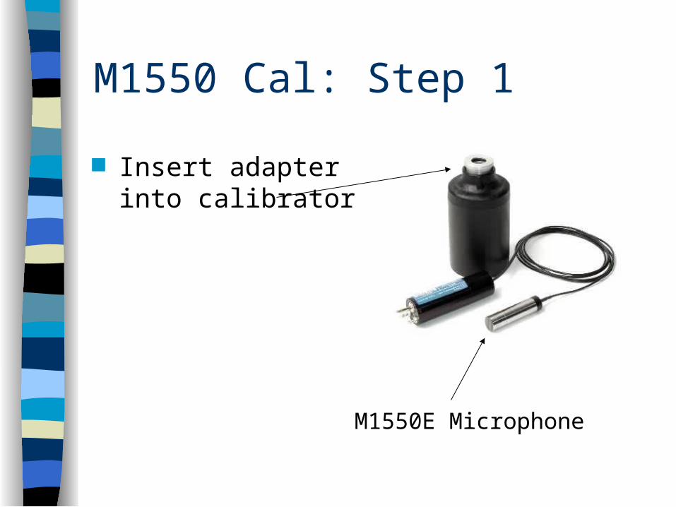
M1550 Cal: Step 1
Insert adapter into calibrator
M1550E Microphone
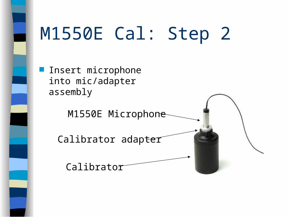
M1550E Cal: Step 2
Insert microphone into mic/adapter assembly
M1550E Microphone
Calibrator
Calibrator adapter
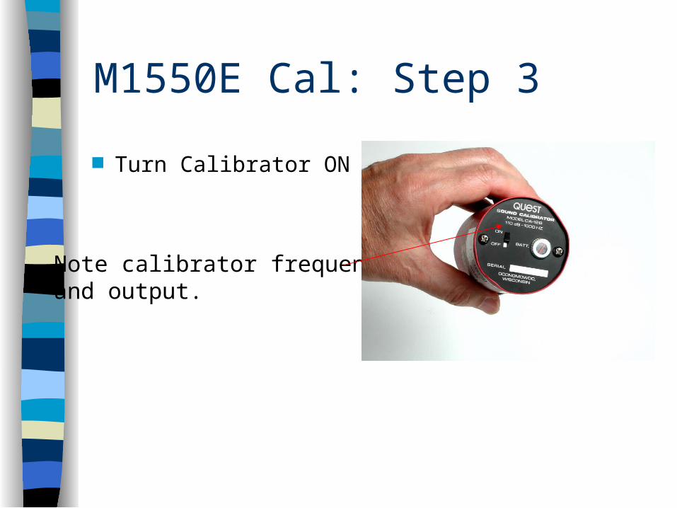
M1550E Cal: Step 3
Turn Calibrator ON
Note calibrator frequencyand output.
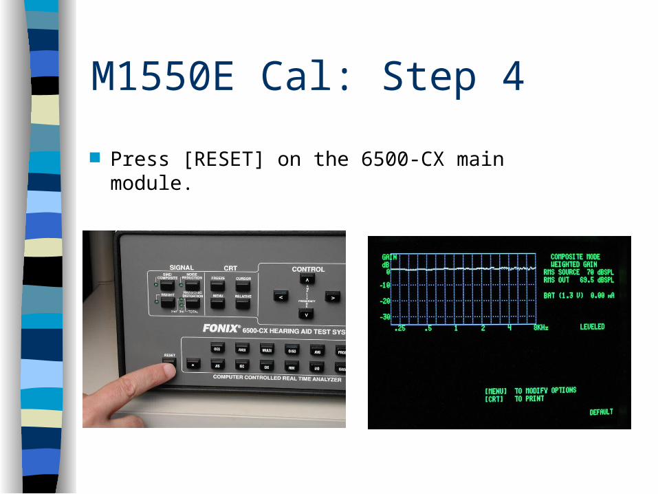
M1550E Cal: Step 4
Press [RESET] on the 6500-CX main module.

M1550E Cal: Step 5 Press [SINE/COMPOSITE] on 6500-CX main
module to put unit in pure tone mode.
Noise reduction set to 4
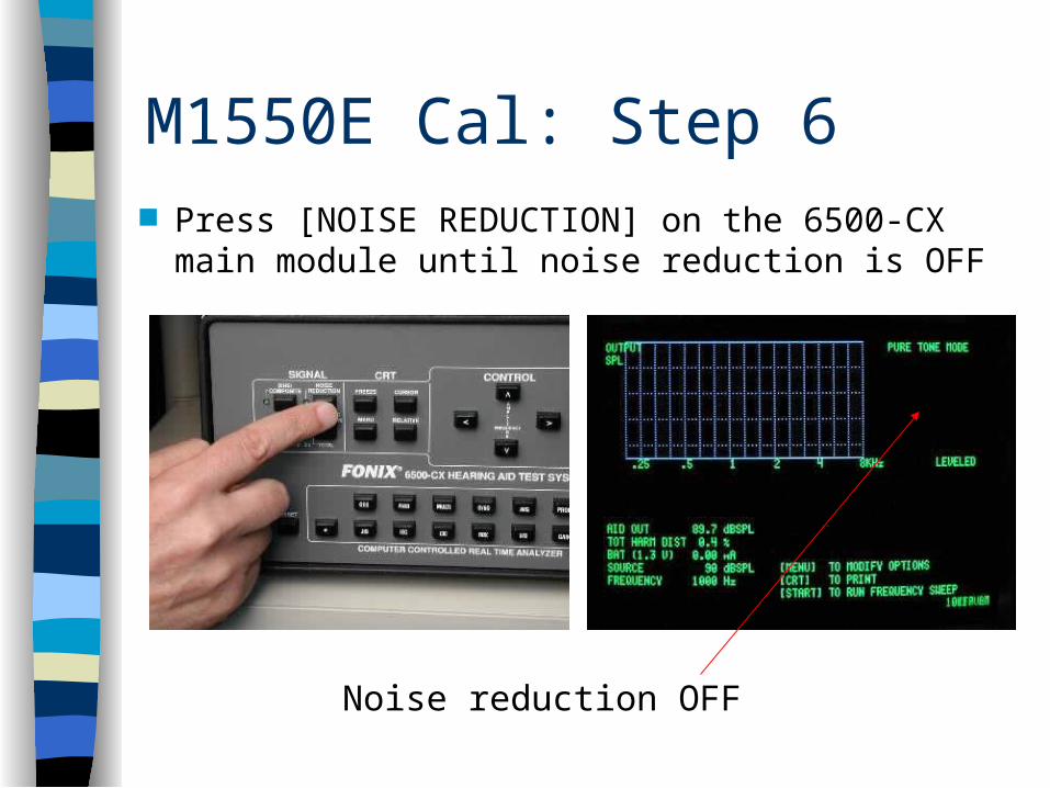
M1550E Cal: Step 6 Press [NOISE REDUCTION] on the 6500-CX
main module until noise reduction is OFF
Noise reduction OFF

M1550E Cal: Step 7
Check that AID OUT matches source of calibrator.
Make sure FREQUENCY matches the calibrator. Adjust with arrow keys if necessary. (Calibrator for this
measurement is 110 dB SPL at 1000 Hz)
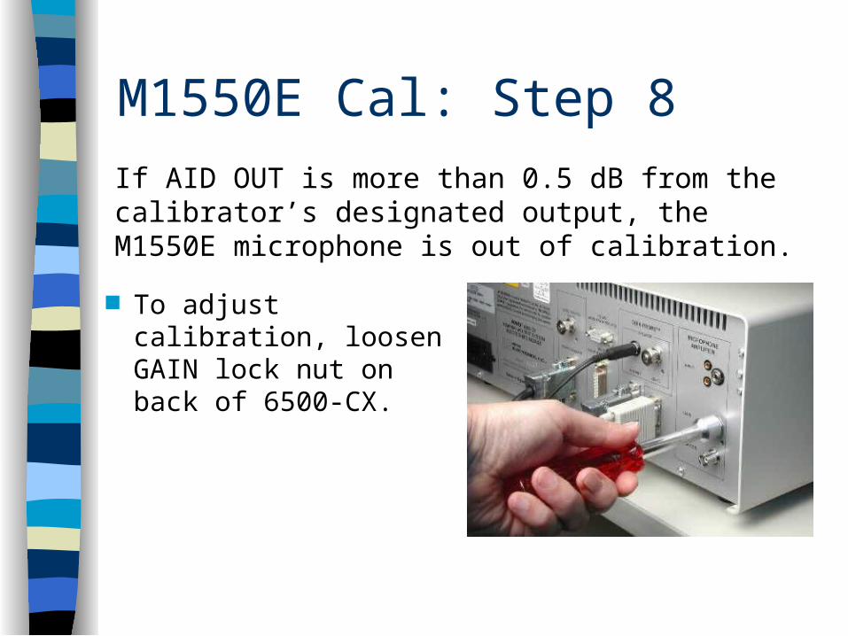
M1550E Cal: Step 8
To adjust calibration, loosen GAIN lock nut on back of 6500-CX.
If AID OUT is more than 0.5 dB from the calibrator’s designated output, the M1550E microphone is out of calibration.

M1550E Cal: Step 9 With flathead screwdriver, adjust GAIN pot
until AID OUT is within 0.5 dB of the calibrator’s output.
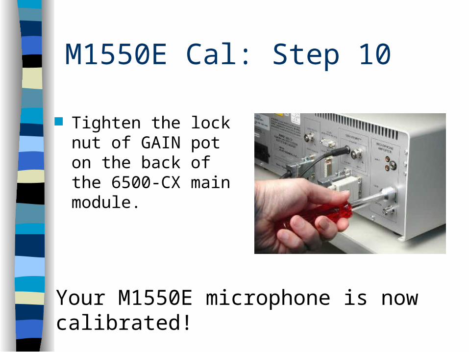
M1550E Cal: Step 10
Tighten the lock nut of GAIN pot on the back of the 6500-CX main module.
Your M1550E microphone is now calibrated!
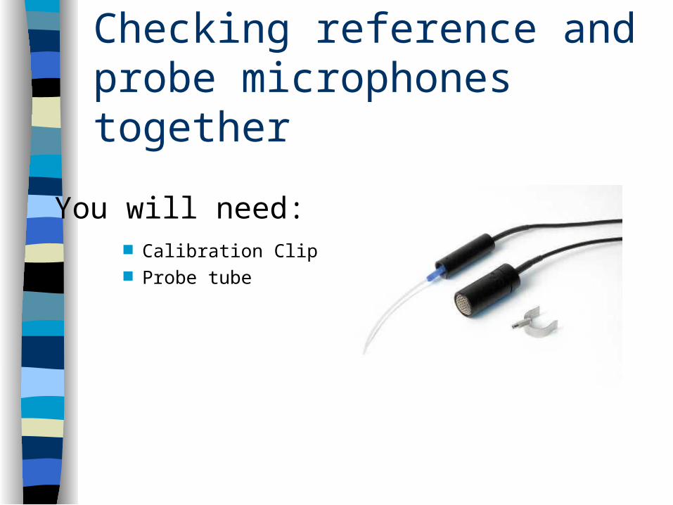
Checking reference and probe microphones together
Calibration Clip Probe tube
You will need:

Ref & Probe check: Step 1
Attach calibration clip to reference microphone

Ref & Probe check: Step 2
Slip probe tube through clip so that tube rests on grill of reference microphone.
Probe tube ends here
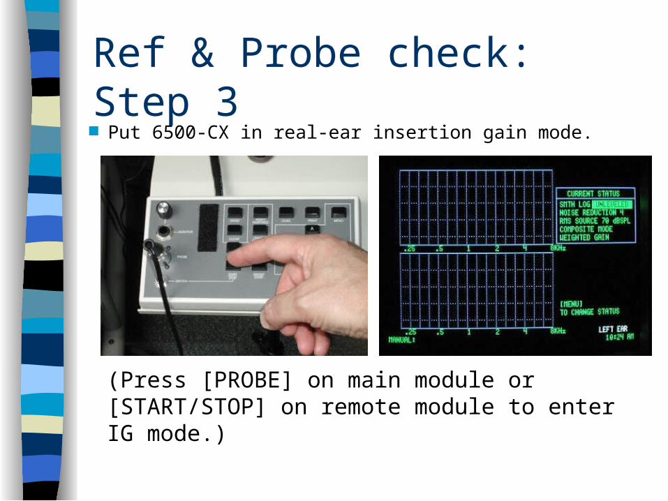
Ref & Probe check: Step 3 Put 6500-CX in real-ear insertion gain mode.
(Press [PROBE] on main module or [START/STOP] on remote module to enter IG mode.)
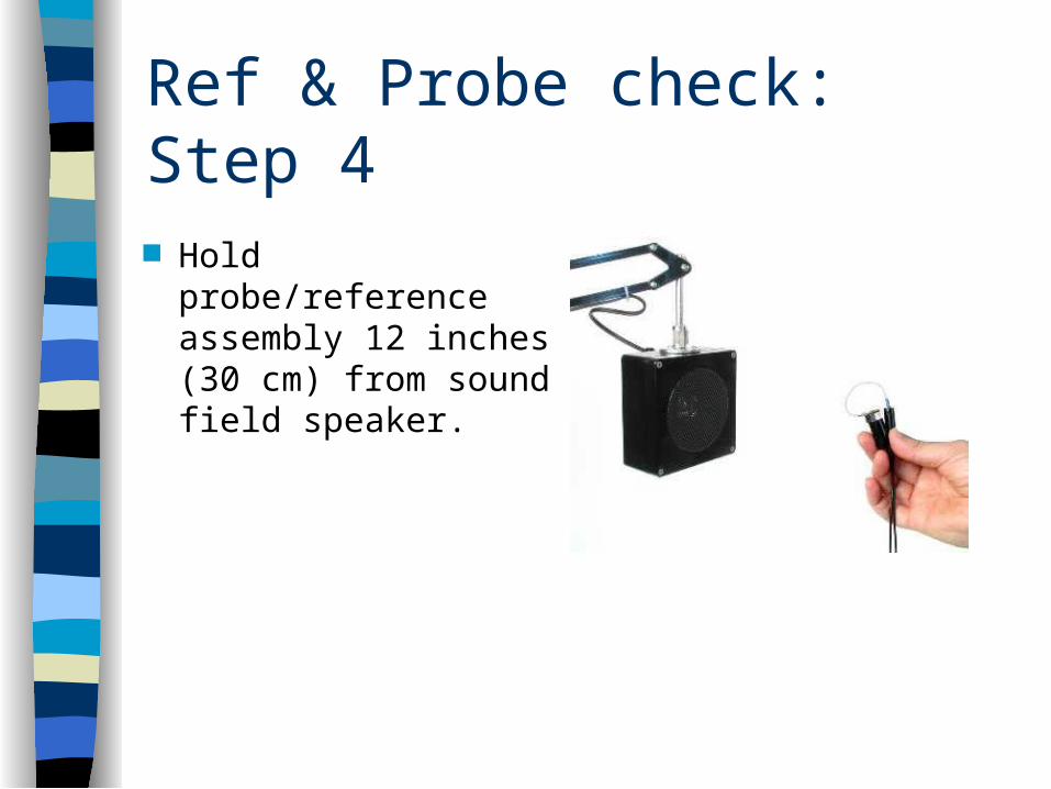
Ref & Probe check: Step 4
Hold probe/reference assembly 12 inches (30 cm) from sound field speaker.

Ref & Probe check: Step 5 Press [START/STOP] on remote module to measure the
response.
The response should be a flat line at 0 dB GAIN.
In calibration Out of calibration
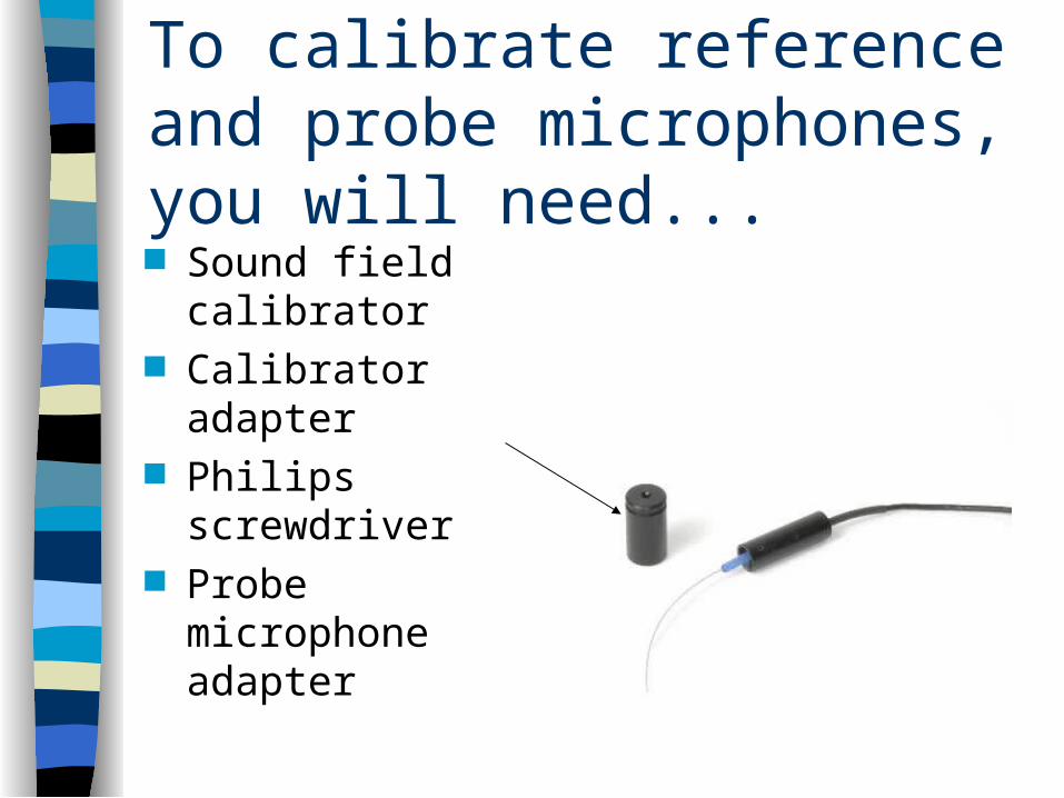
To calibrate reference and probe microphones, you will need... Sound field calibrator Calibrator adapter Philips screwdriver Probe microphone
adapter
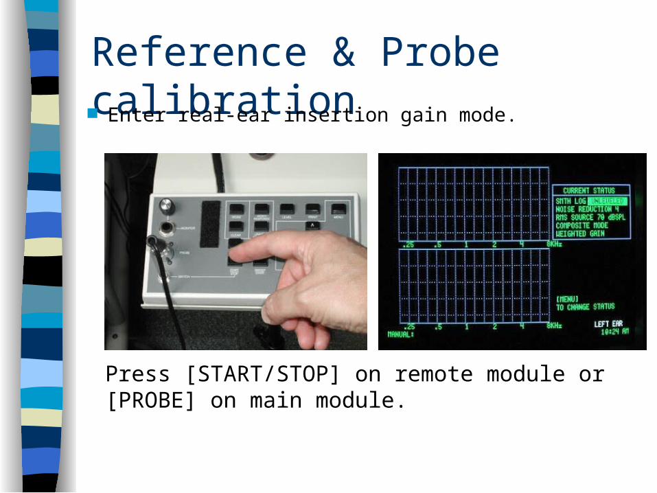
Reference & Probe calibration Enter real-ear insertion gain mode.
Press [START/STOP] on remote module or [PROBE] on main module.

Reference & Probe calibration Press [MENU] to enter Quik-Probe II menu. Highlight CALIBRATE PROBE using up-down arrow keys.

Reference & Probe calibration Press [START/STOP] to enter probe calibration
screen.
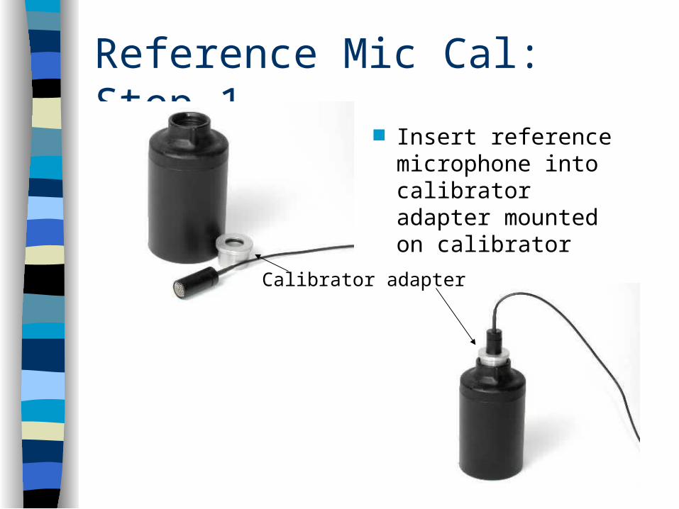
Reference Mic Cal: Step 1 Insert reference
microphone into calibrator adapter mounted on calibrator
Calibrator adapter

Reference Mic Cal: Step 2
Turn calibrator ON
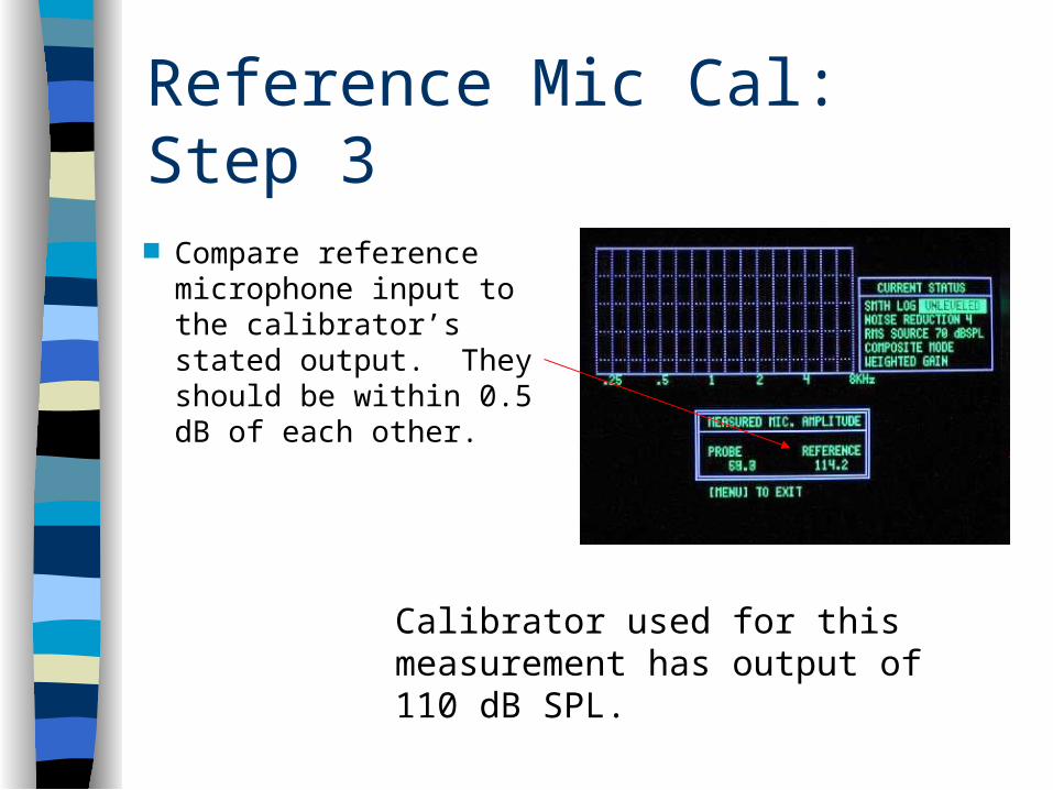
Reference Mic Cal: Step 3
Compare reference microphone input to the calibrator’s stated output. They should be within 0.5 dB of each other.
Calibrator used for this measurement has output of 110 dB SPL.

Reference Mic Cal: Step 4 If necessary, use screwdriver to make adjustments to reference pot on
bottom of remote module.
Reference pot Ref mic at correct level
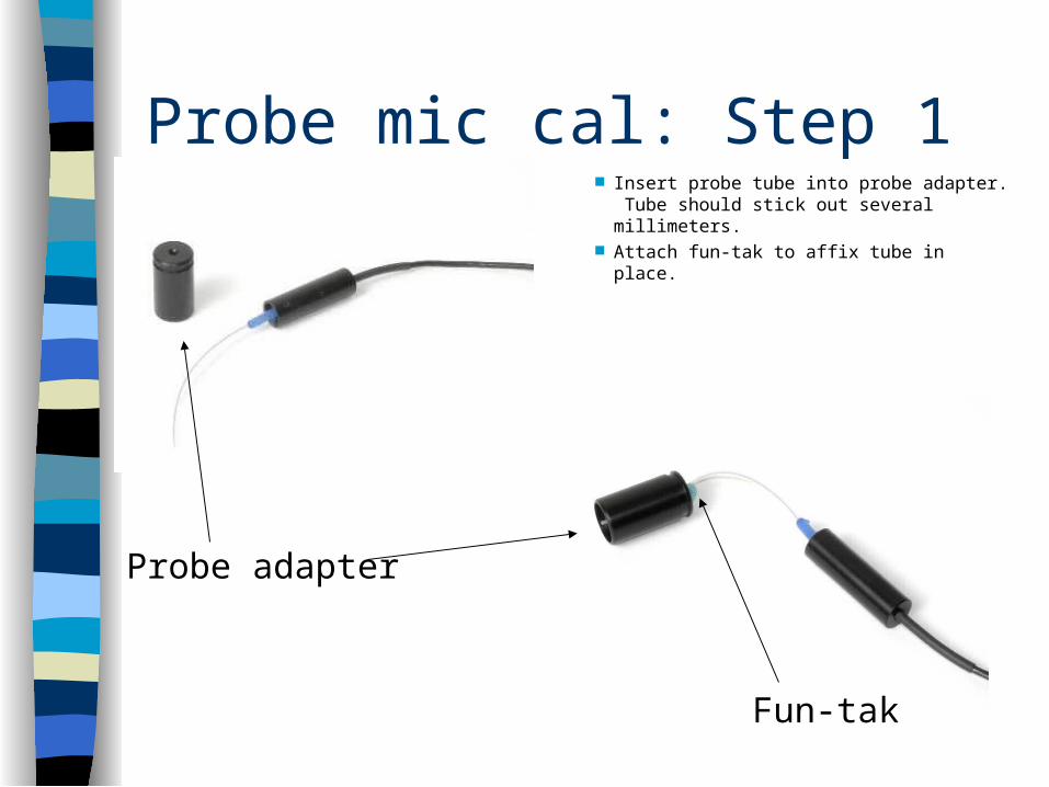
Probe mic cal: Step 1
Probe adapter
Fun-tak
Insert probe tube into probe adapter. Tube should stick out several millimeters.
Attach fun-tak to affix tube in place.
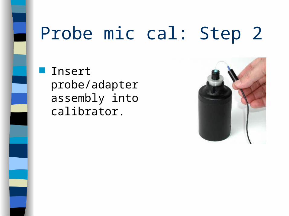
Probe mic cal: Step 2
Insert probe/adapter assembly into calibrator.

Probe mic cal: Step 3
Turn calibrator ON
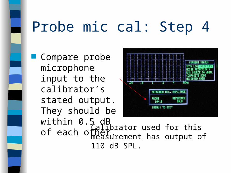
Probe mic cal: Step 4
Compare probe microphone input to the calibrator’s stated output. They should be within 0.5 dB of each other.
Calibrator used for this measurement has output of 110 dB SPL.
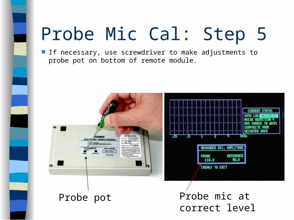
Probe Mic Cal: Step 5 If necessary, use screwdriver to make adjustments to probe pot on bottom
of remote module.
Probe mic at correct level
Probe pot
All your microphones should now be calibrated!
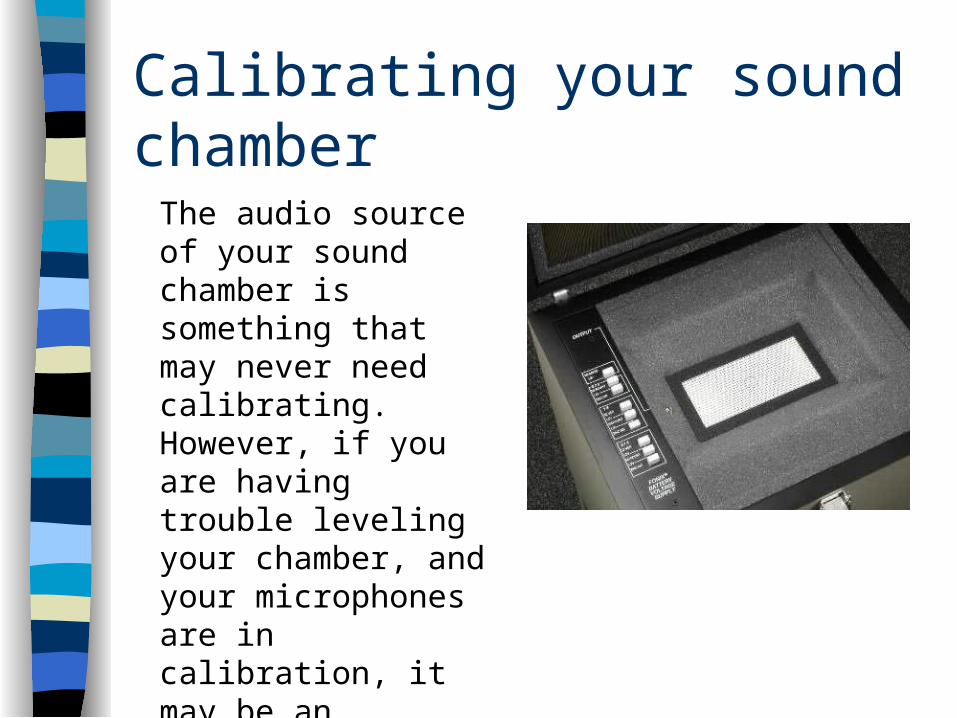
Calibrating your sound chamber
The audio source of your sound chamber is something that may never need calibrating. However, if you are having trouble leveling your chamber, and your microphones are in calibration, it may be an indication that your sound chamber needs to be looked at.

Step 1 Press [RESET] to enter main coupler screen.

Step 2 Press [WEIGHT] twice to put analyzer in
composite unweighted mode.
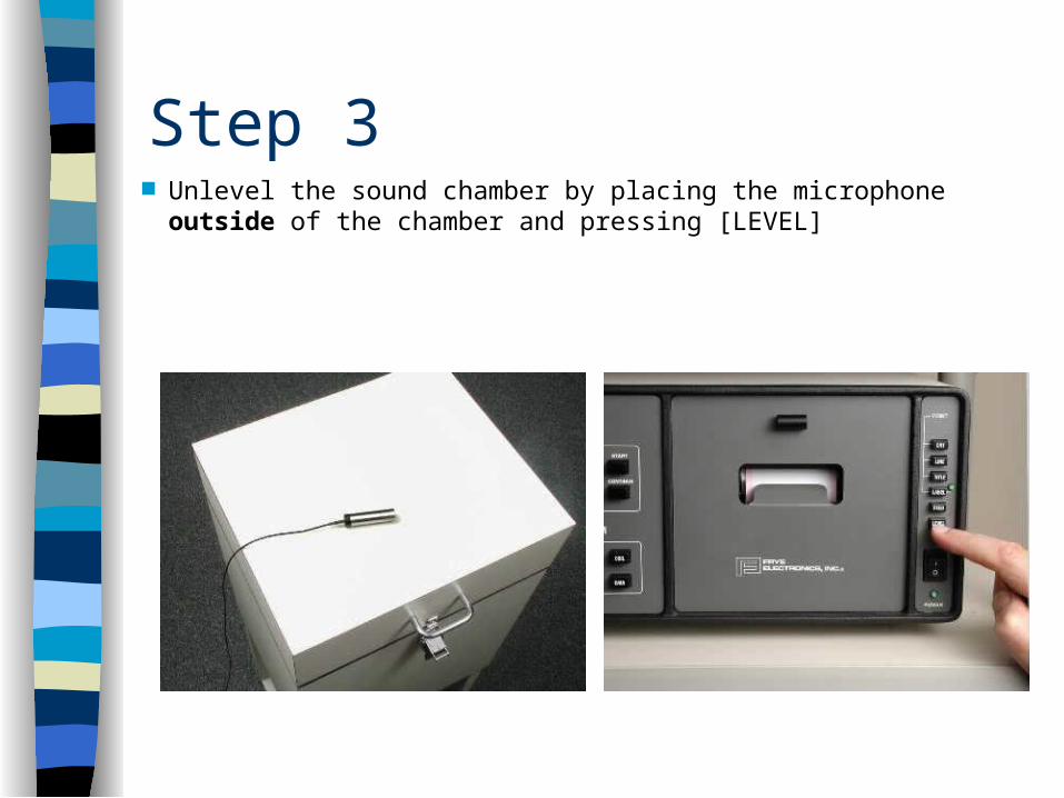
Step 3 Unlevel the sound chamber by placing the microphone outside
of the chamber and pressing [LEVEL]
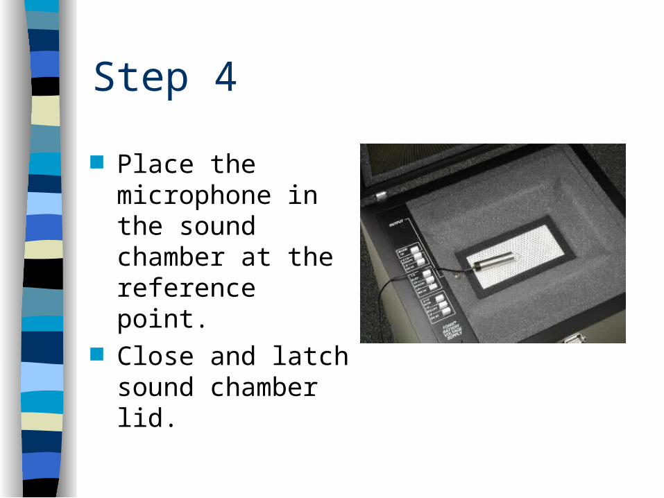
Step 4
Place the microphone in the sound chamber at the reference point.
Close and latch sound chamber lid.

Step 5
Verify that the RMS OUT on the video screen is within 0.5 dB of the RMS SOURCE.
RMS Out
RMS Source

Step 6
If the source needs adjustment, loosen the AUDIO SOURCE LEVEL lock nut on the back of the 6500-CX main module.

Step 7 Using a flathead screwdriver, adjust the AUDIO SOURCE LEVEL pot
on the back of the 6500-CX so that RMS OUT is within 0.5 dB of RMS Source.

Step 8
Tighten the lock nut again to keep the new source level.
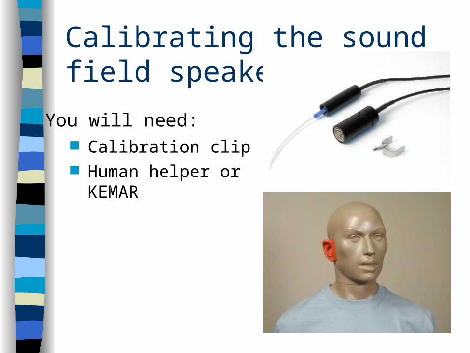
Calibrating the sound field speaker
Calibration clip Human helper or
KEMAR
You will need:
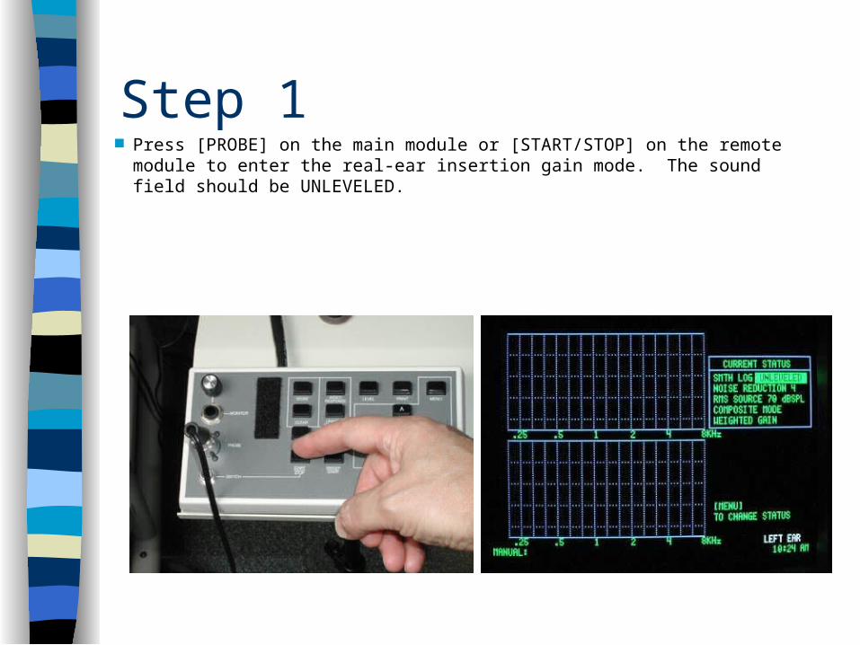
Step 1 Press [PROBE] on the main module or [START/STOP] on the remote module to
enter the real-ear insertion gain mode. The sound field should be UNLEVELED.
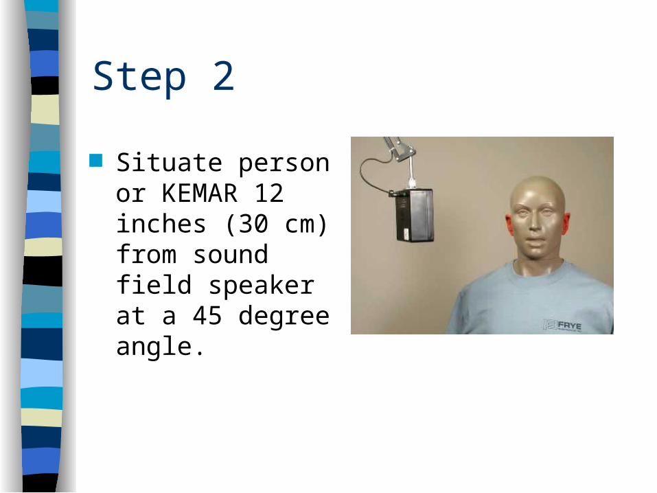
Step 2
Situate person or KEMAR 12 inches (30 cm) from sound field speaker at a 45 degree angle.
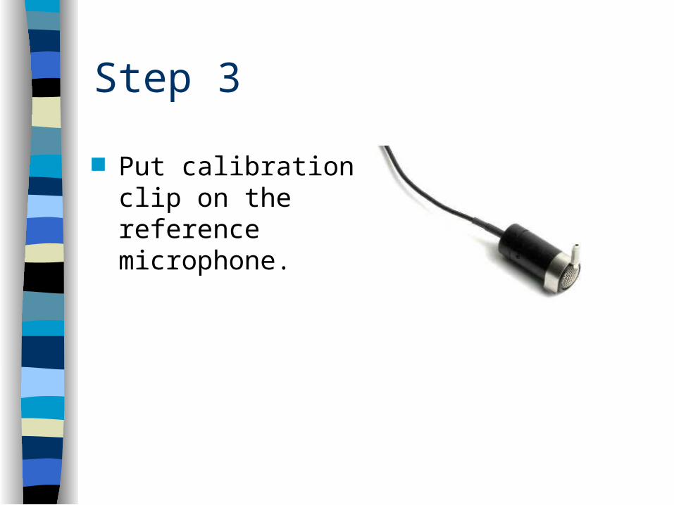
Step 3
Put calibration clip on the reference microphone.
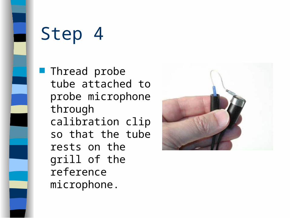
Step 4
Thread probe tube attached to probe microphone through calibration clip so that the tube rests on the grill of the reference microphone.

Step 5
Place both microphones above the ear nearest to the sound field speaker.
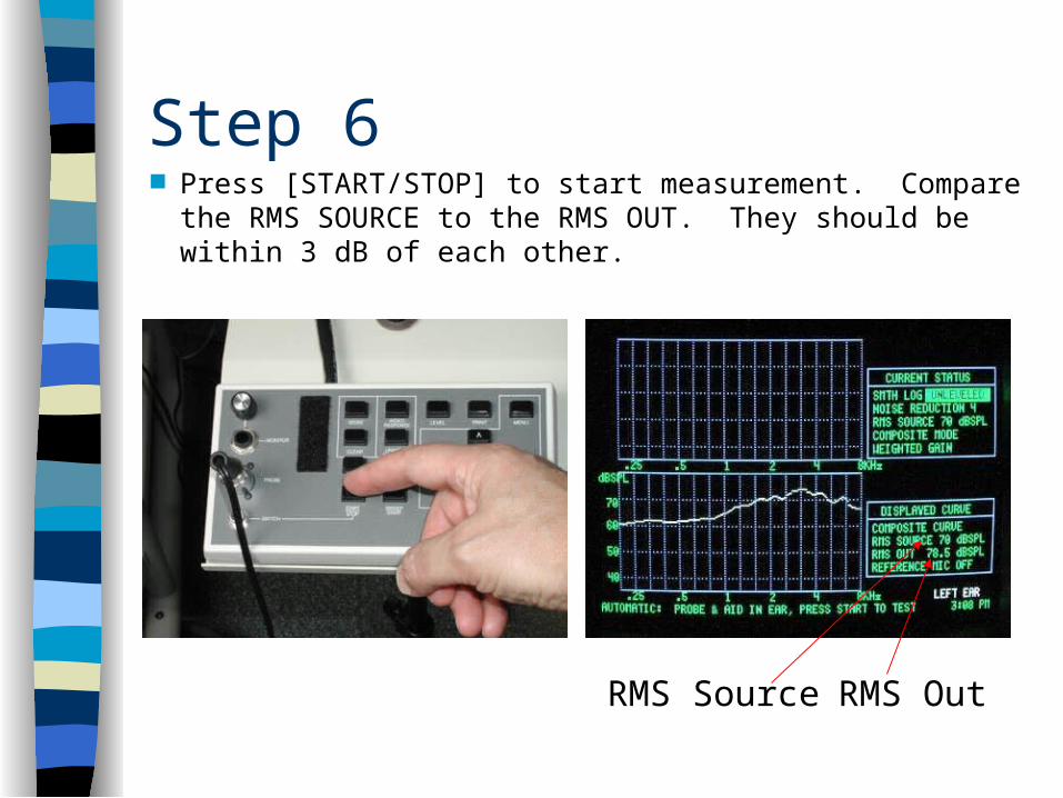
Step 6 Press [START/STOP] to start measurement. Compare the RMS
SOURCE to the RMS OUT. They should be within 3 dB of each other.
RMS Source RMS Out

Step 7
To adjust the sound level of the speaker, locate the LEVEL pot on the back of the main 6500-CX module.
Loosen the lock nut.

Step 8 Use a flathead screwdriver to adjust the source level
until RMS OUT is within 3 dB of RMS SOURCE.
Old level New level
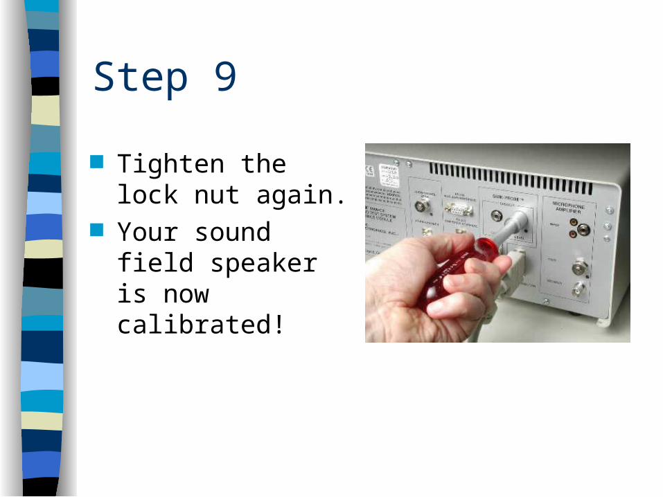
Step 9
Tighten the lock nut again.
Your sound field speaker is now calibrated!


