
7.0 mm Cannulated Screws. Part ofthe Synthes Cannulated Screw System.
Technique Guide

Introduction
Surgical Technique
Product Information
Table of Contents
7.0 mm Cannulated Screws 2
AO Principles 3
Indications 4
Surgical Technique Tips 5
Percutaneous Technique 6
Open Technique 11
Implants 13
Instruments 14
Set List 17
Image intensifier control
Synthes
7.0 mm Cannulated Screws
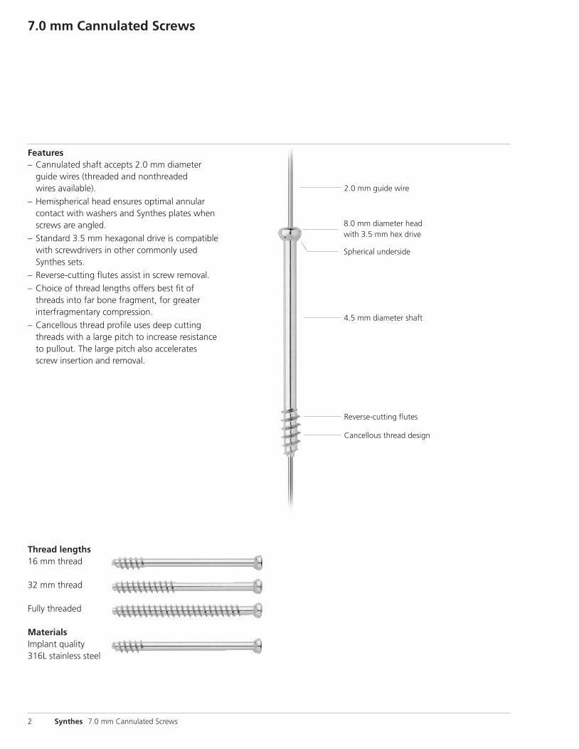
Features– Cannulated shaft accepts 2.0 mm diameter
guide wires (threaded and nonthreaded wires available).
– Hemispherical head ensures optimal annularcontact with washers and Synthes plates whenscrews are angled.
– Standard 3.5 mm hexagonal drive is compatiblewith screwdrivers in other commonly used Synthes sets.
– Reverse-cutting flutes assist in screw removal.
– Choice of thread lengths offers best fit ofthreads into far bone fragment, for greater interfragmentary compression.
– Cancellous thread profile uses deep cuttingthreads with a large pitch to increase resistanceto pullout. The large pitch also acceleratesscrew insertion and removal.
2 Synthes 7.0 mm Cannulated Screws
Cancellous thread design
Reverse-cutting flutes
2.0 mm guide wire
4.5 mm diameter shaft
Spherical underside
8.0 mm diameter headwith 3.5 mm hex drive
Thread lengths16 mm thread
32 mm thread
Fully threaded
MaterialsImplant quality 316L stainless steel
AO Principles
Synthes 3
In 1958, the AO formulated four basic principles, which havebecome the guidelines for internal fixation.1 These principles,as applied to cannulated screws, are:
Anatomic reductionA guide wire marks the prescribed path for the cannulatedscrew and secures alignment of the fragments while thescrew is being inserted. The cannulated screw is insertedover the wire and tightened to further compress the fragments and hold the reduction.
Stable fixationCannulated screws provide interfragmentary compressionand absolute stability across the fracture. The screws areavailable in different threads lengths, allowing the surgeonto optimize purchase in the far fragment for maximum compression and stability.
Preservation of blood supplyThe use of small diameter guide wires allows precise place-ment of cannulated screws through small incisions. Thistechnique minimizes disruption of soft tissue and preservesvascular blood flow for bone healing.
Early, active mobilizationCannulated screws, combined with AO technique, providestable fracture fixation with minimal trauma to vascular supply. This helps to create an improved environment forbone healing, accelerating the patient’s return to previousmobility and function.
1. M.E. Müller, M. Allgöwer, R. Schneider, and H. Willenegger. Manual ofInternal Fixation, 3rd Edition. Berlin: Springer-Verlag. 1991.

Indications
4 Synthes 7.0 mm Cannulated Screws
7.0 mm Cannulated ScrewsFor fracture fixation of large bones and large bone fragments.
Warning: This device is not approved for screw attachmentor fixation to the posterior elements (pedicles) of the cervical, thoracic or lumbar spine.

Synthes 5
Surgical Technique Tips
Cleaning cannulations
Instruments
319.27 Cleaning Brush
319.36 2.0 mm Cleaning Stylet
Cleaning the cannulation in each instrument is imperative for proper function. Instruments should be cleared intraopera-tively with the 2.0 mm cleaning stylet to prevent accu mu lationof debris in the cannulation and potential binding of the instruments about the guide wire. Instruments should becleaned post operatively with the stylet and the cleaning brush.
DrillingBecause of their hollow cross section and long length, cannulated drill bits are more susceptible to breakage than solid drill bits of the same diameter. Use less axial force, avoid bending, and advance the drill bit slowly to minimize the possibility of breakage. Cannulated drill bitsshould be inspected after every procedure and replaced ifworn or damaged.

1Insert guide wire
Instruments
319.31 2.0 mm Trocar
319.32 4.5 mm/2.0 mm Drill Sleeve
319.33 8.0 mm/4.5 mm Drill Sleeve
319.34 11.0 mm/8.0 mm Protection Sleeve
Make a stab incision and insert the percutaneous sleeve assembly (11.0 mm/8.0 mm protection sleeve, 8.0 mm/4.5 mm and 4.5 mm/2.0 mm drill sleeves, and 2.0 mm trocar) through the soft tissue to the bone. Remove the trocar and insert a 2.0 mm threaded guide wire to the appropriate depth. Confirm wire placement under image intensification. Remove all sleeves.
Technique tips:To prevent slippage, the 4.5 mm/2.0 mm drill sleeve may betapped with a hammer to seat the teeth in the lateral surface.
Run the drill at maximum speed to minimize deflection whilegradually advancing the guide wire.
Percutaneous Technique
6 Synthes 7.0 mm Cannulated Screws

Synthes 7
2Insert additional parallel wires (if necessary)
Instruments
319.30 4.5 mm Parallel Drill Guide
319.31 2.0 mm Trocar
319.32 4.5 mm/2.0 mm Drill Sleeve
Insert one 4.5 mm/2.0 mm drill sleeve into the outer-most 4.5 mm hole of the parallel drill guide. Place this combina-tion over the previously inserted guide wire and push directlyto the bone.
Insert a second 4.5 mm/2.0 mm drill sleeve and the 2.0 mmtrocar into any of the other three holes in the parallel drillguide and press the trocar to the near cortex. Remove thetrocar and insert a guide wire through the 4.5 mm/2.0 mmdrill sleeve. Insert any additional guide wires following thesame procedure and then replace the drill guide with thepercutaneous sleeve assembly over one of the guide wires.
Technique tip: Avoid placing any bending forces on the firstguide wire, as this will affect parallelism.
Notes:Any previously inserted guide wire can be used in the outer -most hole of the guide for parallel placement of the nextguide wire.
Possible distances between parallel guide wires are 10 mm,14 mm and 18 mm, measured from the center of the primary hole of the parallel drill guide to the centers of the other holes. Plan placement of each guide wire based on these distances.

3Measure for screw length
Instruments
319.21 Cannulated Screw Measuring Device
319.32 4.5 mm/2.0 mm Drill Sleeve
Remove the two inner drill sleeves. Slide the tapered end ofthe cannulated screw measuring device over the guide wire.This reading determines appropriate screw length. Select a 7.0 mm cannulated screw of this length, with a thread whichengages only the opposite fragment, and set it aside.
Note: Screw length will be 8 mm short of the guide wire tip (the length of the threaded portion of the wire), preventingpenetration of the far cortex.
Percutaneous Technique continued
8 Synthes 7.0 mm Cannulated Screws

Synthes 9
4Predrill
Instruments
310.69 4.5 mm Cannulated Drill Bit
319.33 8.0 mm/4.5 mm Drill Sleeve
Place the 8.0 mm/4.5 mm drill sleeve into the protectionsleeve, and drill with the 4.5 mm cannulated drill bit underimage intensification to the appropriate depth, being carefulnot to drill over the guide wire threads and penetrate the farcortex. Remove the 8.0 mm/4.5 mm drill sleeve.
Technique tip: Avoid directing the drill bit; let it follow theguide wire. Take care to remove the drill bit slowly and topull back straight while running the drill forward to preventguide wire pullout.
Notes:Depending on bone quality, the surgeon may choose to drillonly the near cortex to prevent inadvertent guide wire pullout.
The calibrations on the cannulated drill bits and the cannulatedtap are read at the surface of the bone and therefore can notbe used when using the percutaneous sleeves. Use image intensification for confirmation of drilling and tapping depths.

5Tap
Instruments
311.69 Cannulated Tap for 7.0 mm Cannulated Screws
319.34 11.0 mm/8.0 mm Protection Sleeve
Where necessary, tap the near cortex with the cannulated tap through the protection sleeve. In dense bone, it may benecessary to tap over the entire nonthreaded length of theguide wire.
6Insert screws
Instruments
314.19 Cannulated Hexagonal Screwdriver
319.34 11.0 mm/8.0 mm Protection Sleeve
Using the cannulated hexagonal screwdriver without theholding sleeve, insert the previously selected screw (Step 3)through the protection sleeve. Remove and discard the guide wire.
Note: In osteopenic bone, use a washer to prevent the screwhead from sinking into bone. Washers cannot be placedthrough the percutaneous sleeve. Remove the sleeve beforeplacing the washer over the guide wire.
Percutaneous Technique continued
10 Synthes 7.0 mm Cannulated Screws
Open Technique
Synthes 11
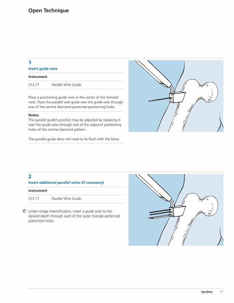
1Insert guide wire
Instrument
312.71 Parallel Wire Guide
Place a positioning guide wire in the center of the femoralneck. Place the parallel wire guide over the guide wire throughone of the central diamond-patterned positioning holes.
Notes: The parallel guide’s position may be adjusted by replacing itover the guide wire through one of the adjacent positioningholes of the central diamond pattern.
The parallel guide does not need to lie flush with the bone.
2Insert additional parallel wires (if necessary)
Instrument
312.71 Parallel Wire Guide
Under image intensification, insert a guide wire to the desired depth through each of the outer triangle-patternedplacement holes.

3Remove guide wire
Remove the parallel guide and the positioning guide wire(inserted in Step 1).
4Insert screws
Measure, drill, tap and insert each screw before proceedingto the next, to prevent loss of reduction.
Open Technique continued
12 Synthes 7.0 mm Cannulated Screws

Implants
Synthes 13
7.0 mm Cannulated Screws, 16 mm thread length– 30 mm–130 mm lengths in 5 mm increments
– 316L stainless steel
7.0 mm Cannulated Screws, 32 mm thread length– 45 mm–130 mm lengths in 5 mm increments
– 316L stainless steel
Washers, 13.0 mm– Prevents screw head from sinking into osteopenic bone

14 Synthes 7.0 mm Cannulated Screws
Instruments
292.65 2.0 mm Threaded Guide Wire, 230 mm
310.19◊ 2.0 mm Drill Bit, 100 mm, quick coupling
310.69◊ 4.5 mm Cannulated Drill Bit, 233 mm, Jacobs chuck
311.69 Cannulated Tap for 7.0 mm CannulatedScrews
312.46 4.5 mm/3.2 mm Double Drill Sleeve
312.71 Parallel Wire Guide
◊ Available nonsterile or sterile-packed. Add S to catalog number for sterile product.

Synthes 15
314.11 Holding Sleeve
314.19 Cannulated Hexagonal Screwdriver
319.21 Cannulated Screw Measuring Device
319.27 2.1 mm Cleaning Brush
319.30 4.5 mm Parallel Drill Guide
319.31 2.0 mm Trocar, 118 mm

16 Synthes 7.0 mm Cannulated Screws
Instruments continued
319.32 4.5 mm/2.0 mm Drill Sleeve, 108 mm
319.33 8.0 mm/4.5 mm Drill Sleeve, 99 mm
319.34 11.0 mm/8.0 mm Protection Sleeve, 88 mm
319.36 2.0 mm Cleaning Stylet
319.97 Screw Forceps

Synthes 17
7.0 mm Cannulated Screw Instrument and Implant Set (105.07)
Graphic Case304.230 7.0 mm Cannulated Screw Instrument and
Implant Set Graphic Case
Instruments292.65 2.0 mm Threaded Guide Wire, 230 mm, 10 ea.
310.19◊ 2.0 mm Drill Bit, 100 mm, quick coupling, 2 ea.
310.69◊ 4.5 mm Cannulated Drill Bit, 233 mm, Jacobs chuck, 2 ea.
311.69 Cannulated Tap for 7.0 mm Cannulated Screws
312.46 4.5 mm/3.2 mm Double Drill Sleeve
312.71 Parallel Wire Guide
314.11 Holding Sleeve
314.19 Cannulated Hexagonal Screwdriver
319.21 Cannulated Screw Measuring Device
319.27 2.1 mm Cleaning Brush
319.30 4.5 mm Parallel Drill Guide
319.31 2.0 mm Trocar, 118 mm, 2 ea.
319.32 4.5 mm/2.0 mm Drill Sleeve, 108 mm, 2 ea.
319.33 8.0 mm/4.5 mm Drill Sleeve, 99 mm
319.34 11.0 mm/8.0 mm Protection Sleeve, 88 mm
319.36 2.0 mm Cleaning Stylet
319.97 Screw Forceps
◊ Available nonsterile or sterile-packed. Add S to catalog number for sterile product.
Note: For additional information, please refer to package insert.
For detailed cleaning and sterilization instructions, please refer tohttp://us.synthes.com/Medical+Community/Cleaning+and+Sterilization.htmor to the below listed inserts, which will be included in the shipping container:—Processing Synthes Reusable Medical Devices—Instruments, Instrument Trays
and Graphic Cases—DJ1305—Processing Non-sterile Synthes Implants—DJ1304

18 Synthes 7.0 mm Cannulated Screws
7.0 mm Cannulated Screw Instrument and Implant Set (105.07) continued
Implants7.0 mm Cannulated Screws, 16 mm thread length
Length (mm) Qty.208.030 30 2208.035 35 2208.040 40 2208.045 45 2208.050 50 2208.055 55 2208.060 60 2208.065 65 2208.070 70 4208.075 75 4208.080 80 4208.085 85 4208.090 90 4208.095 95 4208.100 100 4208.105 105 2208.110 110 2208.115 115 2208.120 120 2208.125 125 2208.130 130 2
Note: For additional information, please refer to package insert.
7.0 mm Cannulated Screws, 32 mm thread length
Length (mm) Qty.209.045 45 2209.050 50 2209.055 55 2209.060 60 2209.065 65 2209.070 70 2209.075 75 2209.080 80 2209.085 85 2209.090 90 2209.095 95 2209.100 100 2209.105 105 2209.110 110 1209.115 115 1209.120 120 1209.125 125 1209.130 130 1
219.99 Washer, for 4.5 mm Cortex and 6.5 mmCancellous Bone Screws, 6 ea.

Synthes
Also Available
Small Battery Drive with 14.4 V Battery Pack Sets105.954H with Hudson Reduction Drive Unit105.954M with Modified Trinkle Reduction Drive Unit105.954T with Trinkle Reduction Drive Unit
105.957 Power Drive Set
Instruments292.651 2.0 mm Threaded Guide Wire, spade point
both ends, 230 mm
292.652 2.0 mm Non-Colored Threaded Guide Wire, spade point, 230 mm
292.656 2.0 mm Non-Threaded Guide Wire, spade point one end, 230 mm, blue
310.79 Cannulated Countersink, for 7.0 mm Cannulated Screws
314.22 Cannulated 3.5 mm Hexagonal Screwdriver Shaft, for 7.0 mm Cannulated Screws
314.27 Large Hexagonal Screwdriver, for removal of 7.0 mm Cannulated Screws
304.234 Screw Rack for 7.0 mm Cannulated Screws, 16 mm and 32 mm Threaded
304.235 Screw Rack for 7.0 mm Cannulated Screws,fully threaded
360.02◊ 7.0 mm Cannulated Drill Bit, large quickcoupling, 90 mm
Implants7.0 mm Cannulated Screws
208.135– 16 mm thread length, 135 mm–150 mm 208.150 (5 mm increments)
209.135– 32 mm thread length, 135 mm–150 mm209.150 (5 mm increments)
209.420– fully threaded, 20 mm–130 mm209.530 (5 mm increments)
◊ Available nonsterile or sterile-packed. Add S to catalog number for sterile product.

Synthes (USA)1302 Wrights Lane EastWest Chester, PA 19380Telephone: (610) 719-5000To order: (800) 523-0322Fax: (610) 251-9056
Synthes (Canada) Ltd.2566 Meadowpine BoulevardMississauga, Ontario L5N 6P9Telephone: (905) 567-0440To order: (800) 668-1119Fax: (905) 567-3185
© 1997 Synthes, Inc. or its affiliates. All rights reserved. Synthes is a trademark of Synthes, Inc. or its affiliates. Printed in U.S.A. 9/10 J2425-G
www.synthes.com


