
7
7-1General Catalogue: 2000/2001 Drives & Systems
SR32 line regen Converters
www.siei.it
7.1 Short description
SR32 devices are AC/DC three-phase converters with a full digital control, which areactive in the four quadrants to supply constant voltage to the DC link of the AMV32,AMD32, AVy and AFy inverters.The SR32 converter is suitable to supply power to both single and multiple invertersystems connected to a common DC link. A part of the regenerated power can beexchanged between the monitoring and regenerating drives; the exceeding power isregenerated back to the Mains via the SR32 converter. The output voltage of theSR32 converter is kept constant within a specified range even if the inverter operatesin a regenerative mode untill it reaches the full current value supplied while functioningin a rectifier mode. This makes it possible to use a SR32 fed inverter in applications requiring a conti-nuous regeneration.
7.2 Identification code
SR32 400 185
SR32 three-phase converterSR32
400 Mains power supply (V)
185 DC link rated output current, class 1 (A)
--
7
General Catalogue: 2000/2001 Drives & Systems7-2
SR32 line regen Converters
www.siei.it
7.3 Converter choice
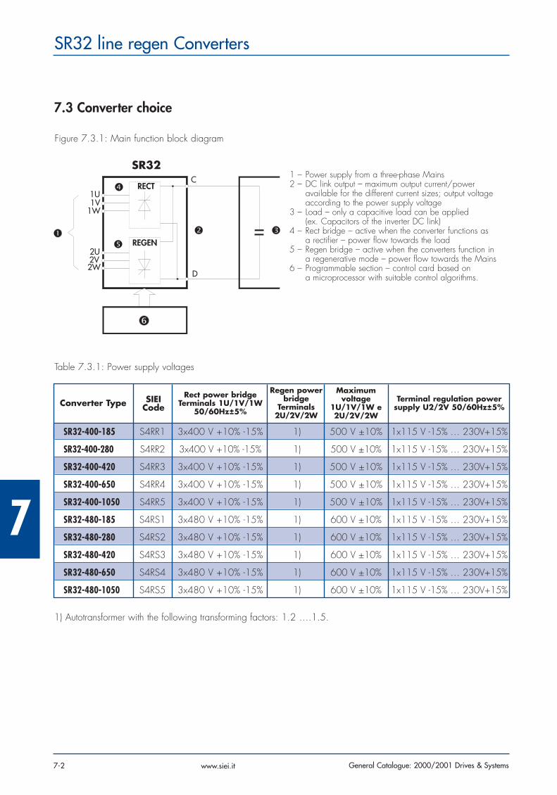
Figure 7.3.1: Main function block diagram
SR32
RECT
REGEN
C
D
2U2V2W
1U1V
1W
1 – Power supply from a three-phase Mains2 – DC link output – maximum output current/power
available for the different current sizes; output voltage according to the power supply voltage
3 – Load – only a capacitive load can be applied (ex. Capacitors of the inverter DC link)
4 – Rect bridge – active when the converter functions as a rectifier – power flow towards the load
5 – Regen bridge – active when the converters function in a regenerative mode – power flow towards the Mains
6 – Programmable section – control card based on a microprocessor with suitable control algorithms.
Table 7.3.1: Power supply voltages
SR32-400-185 S4RR1 3x400 V +10% -15% 1) 500 V ±10% 1x115 V -15% … 230V+15%
SR32-400-280 S4RR2 3x400 V +10% -15% 1) 500 V ±10% 1x115 V -15% … 230V+15%
SR32-400-420 S4RR3 3x400 V +10% -15% 1) 500 V ±10% 1x115 V -15% … 230V+15%
SR32-400-650 S4RR4 3x400 V +10% -15% 1) 500 V ±10% 1x115 V -15% … 230V+15%
SR32-400-1050 S4RR5 3x400 V +10% -15% 1) 500 V ±10% 1x115 V -15% … 230V+15%
SR32-480-185 S4RS1 3x480 V +10% -15% 1) 600 V ±10% 1x115 V -15% … 230V+15%
SR32-480-280 S4RS2 3x480 V +10% -15% 1) 600 V ±10% 1x115 V -15% … 230V+15%
SR32-480-420 S4RS3 3x480 V +10% -15% 1) 600 V ±10% 1x115 V -15% … 230V+15%
SR32-480-650 S4RS4 3x480 V +10% -15% 1) 600 V ±10% 1x115 V -15% … 230V+15%
SR32-480-1050 S4RS5 3x480 V +10% -15% 1) 600 V ±10% 1x115 V -15% … 230V+15%
Converter Type SIEICode
Rect power bridgeTerminals 1U/1V/1W
50/60Hz±5%
Regen powerbridge
Terminals2U/2V/2W
Maximum voltage
1U/1V/1W e2U/2V/2W
Terminal regulation powersupply U2/2V 50/60Hz±5%
1) Autotransformer with the following transforming factors: 1.2 ….1.5.
7
7-3General Catalogue: 2000/2001 Drives & Systems
SR32 line regen Converters
www.siei.it
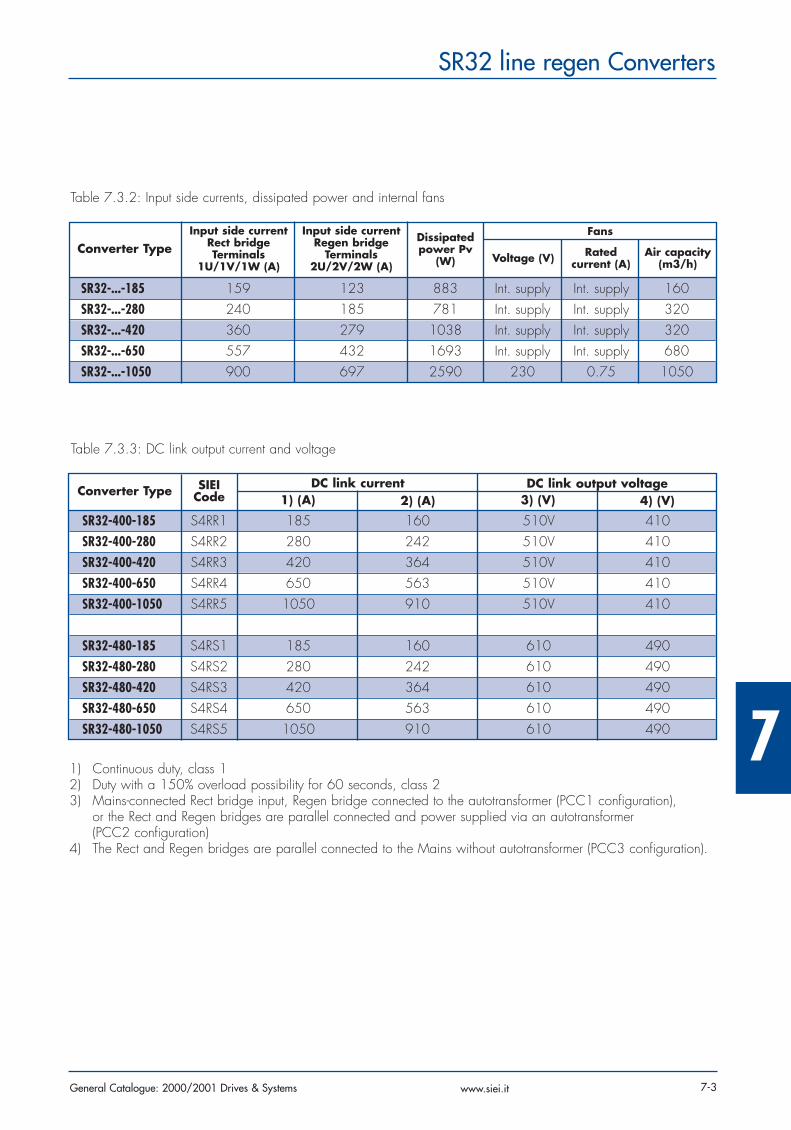
Table 7.3.2: Input side currents, dissipated power and internal fans
SR32-...-185 159 123 883 Int. supply Int. supply 160SR32-...-280 240 185 781 Int. supply Int. supply 320SR32-...-420 360 279 1038 Int. supply Int. supply 320SR32-...-650 557 432 1693 Int. supply Int. supply 680SR32-...-1050 900 697 2590 230 0.75 1050
Converter TypeInput side current
Rect bridgeTerminals
1U/1V/1W (A)
Input side current Regen bridge
Terminals2U/2V/2W (A)
Dissipatedpower Pv
(W)
Fans
Voltage (V) Rated current (A)
Air capacity(m3/h)
Table 7.3.3: DC link output current and voltage
SR32-400-185 S4RR1 185 160 510V 410SR32-400-280 S4RR2 280 242 510V 410SR32-400-420 S4RR3 420 364 510V 410SR32-400-650 S4RR4 650 563 510V 410SR32-400-1050 S4RR5 1050 910 510V 410
SR32-480-185 S4RS1 185 160 610 490SR32-480-280 S4RS2 280 242 610 490SR32-480-420 S4RS3 420 364 610 490SR32-480-650 S4RS4 650 563 610 490SR32-480-1050 S4RS5 1050 910 610 490
Converter Type SIEICode
DC link current DC link output voltage1) (A) 2) (A) 3) (V) 4) (V)
1) Continuous duty, class 12) Duty with a 150% overload possibility for 60 seconds, class 23) Mains-connected Rect bridge input, Regen bridge connected to the autotransformer (PCC1 configuration),
or the Rect and Regen bridges are parallel connected and power supplied via an autotransformer (PCC2 configuration)
4) The Rect and Regen bridges are parallel connected to the Mains without autotransformer (PCC3 configuration).
7
General Catalogue: 2000/2001 Drives & Systems7-4
SR32 line regen Converters
www.siei.it
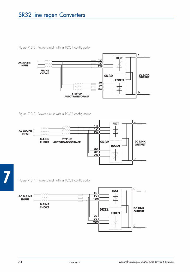
Figure 7.3.2: Power circuit with a PCC1 configuration
AC MAINSINPUT
MAINSCHOKE
STEP-UPAUTOTRANSFORMER
2U2V2W
1U1V1W
SR32
RECT
REGEN
DC LINKOUTPUT
D
C
Figure 7.3.3: Power circuit with a PCC2 configuration
AC MAINSINPUT
MAINSCHOKE
STEP-UPAUTOTRANSFORMER
1U1V1W
2U2V2W
SR32
RECT
REGEN
DC LINKOUTPUT
C
D
Figure 7.3.4: Power circuit with a PCC3 configuration
AC MAINSINPUT
MAINSCHOKE
1U1V1W
2U2V2W
SR32
RECT
REGEN
DC LINKOUTPUT
C
D

7
7-5General Catalogue: 2000/2001 Drives & Systems
SR32 line regen Converters
www.siei.it
7.4 Weights and dimensions
Figure 7.4.1: Dimensions
ac
b
1 a1b1
2
a1
b1
b1
Table 7.4.1: Weights and dimensions
SR32-...-185 1 311 361 368 275 375 M6 18
SR32-...-280 1 311 361 368 275 375 M6 26
SR32-...-420 1 311 361 368 275 375 M6 30
SR32-...-650 1 311 391 368 275 375 M6 31
SR32-...-1050 2 525 554 434 500 200 M6 63
Converter Type Form a(mm)
b(mm)
c(mm)
a1(mm)
b1(mm) Ø Weight
(kilos)

7
General Catalogue: 2000/2001 Drives & Systems7-6
SR32 line regen Converters
www.siei.it
Display configuration for the value readingProgrammable analog outputs to take the value readingsignal on an external displaying device.Identification function for the measurement of the powercircuit parameters and automatic calculation of someregulation parameters used for an easier commissio-ning.Signal internal conditioning (gains, min/max limits, offset…)Control of the power Feed Forward for particular applications with high dynamic needs.Device use:- via the terminal strip- via the keypad- via a PC program- via a Field Bus connection
IsolationHigh impedance galvanic separation between thepower and the regulation section.Galvanic separation between the regulation section andthe digital I/O terminals.
Protection functionsHigh number of protection functions, some with a parti-cular configuration of the converter behavior in case ofan alarm condition.Message storage for the last 10 alarm interventions andindication of the period when the alarm intervened.Temperature linear sensor for an easy control of theheatsink temperature. Converter overload control based on the simulation ofthe I2t function with a warning signal possibility.
Inputs/Outputs- 2 programmable analog outputs- 1 dedicated analog input- 4 dedicated digital inputs- 4 programmable digital inputs- 4 programmable digital outputs- 2 dedicated relay outputs- 1 programmable relay output
Environmental Conditions:Enclosure: IP20Ambient temperature: from 0 to 55°C; if the temperatu-re is higher than 40°C, reduce the current by 1.25%every K. Humidity: from 5% to 85%, 1 g/m3 up to 25 g/m3without condensing or icing.Altitude: up to 1000 meters above sea level; if suchvalue is exceeded, the current has to be reduced by1.2% every 100-meter increase.
Norms and marksEC: in compliance with the EEC directive about low-vol-tage devicesEMC: in compliance with the EEC directive about theelectromagnetic compatibility using option filtersUL/cUL, UL508C norm.
7.5 General features
7
7-7General Catalogue: 2000/2001 Drives & Systems
SR32 line regen Converters
www.siei.it
7.6 Options
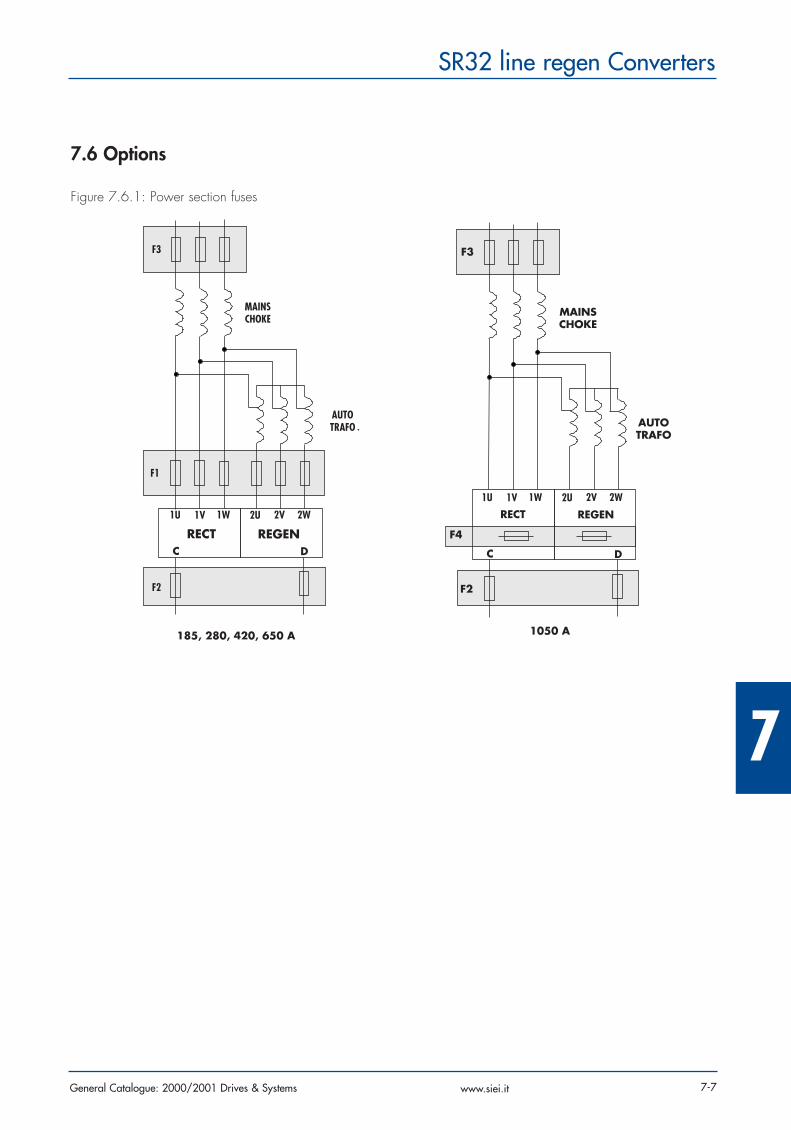
Figure 7.6.1: Power section fuses
F3
MAINSCHOKE
AUTOTRAFO
F1
F2
1U 1V 1W 2U 2V 2W
RECT REGENC D
185, 280, 420, 650 A 1050 A
F2
F4
C
RECT REGEN
D
1U 1V 1W 2U 2V 2W
AUTOTRAFO
MAINSCHOKE
F3

7
General Catalogue: 2000/2001 Drives & Systems7-8
SR32 line regen Converters
www.siei.it
Power section fusesIn order to protect the thyristors on both power bridges it is necessary to use super fast fuses. The line and autotransformer protection requires the use of time-delay fuses. The table lists the suggested fuses.
SR32-…-185 F1 6 S00üf1/80/200A/660V F4G23 A70P175 FWP175A S7G57F2 2 S00üf1/80/200A/660V F4G23 A70P200 FWP200A S7G58F3 3 M1gL 200 F3B63 M1gL 200 F3B63
SR32-…-280 F1 6 S1üf1/110/250A/660V F4G28 A70P250 FWP250A S7G59F2 2 S1üf1/110/315A/660V F4G30 A70P300 FWP300A S7G60F3 3 M2gL 250 F3B65 M2gL 250 F3B65
SR32-…-420 F1 6 S2üf1/110/400A/660V F4G34 A70P400 FWP400A S7G62F2 2 S1üf01/80/450A/660V A70P500 FWP500A S7G63F3 3 M3gL 400 F3C10 M3gL 400 F3C10
SR32-…-650 F1 6 S2üf1/110/630A/660V F4E31 A70P600 FWP600A S7G65F2 2 S2üf01/110/710A/660V F4G85 A70P700 FWP700A S7G67F3 3 M4agL 630 M4agL 630
SR32-…-1050 F2 2 S3üf01/110/1250A/500V A70P1200 FWP1200AF3 3 M4agL 1000 M4agL 1000F4 6 170M5466 S827B 170M5466 S827B
Converter Type Symbol Piecenumber
Suggested fusesEUROPE USA
Type TypeCode Code
a- F1: External fuses for the Rect and Regen bridges of the input side converter- F2: External fuses for the DC link output- F3: External fuses for the line protection- F4: Internal fuses for the Rect and Regen bridges only for the 1050A size- When several fuses are listed for the same code, it means that they are interchangeable.- For SR32-…-1050 sizes the F1 fuses are integrated in the device. They are also supplied with a fuse intervention
internal signaling.
The fuse technical data, such as dimensions, weights, dissipated power, fuse blocks etc. can be found in the catalo-gue of the fuse producer: Jean Muller, Eltville = types S00… , S1… , S3… , M…
Gould Shawmut = A70P… , A2…Bussmann = FWP…, 170M…
7
7-9General Catalogue: 2000/2001 Drives & Systems
SR32 line regen Converters
www.siei.it
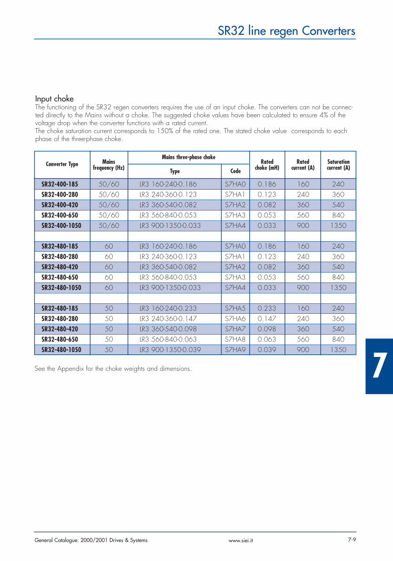
Input chokeThe functioning of the SR32 regen converters requires the use of an input choke. The converters can not be connec-ted directly to the Mains without a choke. The suggested choke values have been calculated to ensure 4% of thevoltage drop when the converter functions with a rated current.The choke saturation current corresponds to 150% of the rated one. The stated choke value corresponds to eachphase of the three-phase choke.
SR32-400-185 50/60 LR3 160-240-0.186 S7HA0 0.186 160 240SR32-400-280 50/60 LR3 240-360-0.123 S7HA1 0.123 240 360SR32-400-420 50/60 LR3 360-540-0.082 S7HA2 0.082 360 540SR32-400-650 50/60 LR3 560-840-0.053 S7HA3 0.053 560 840SR32-400-1050 50/60 LR3 900-1350-0.033 S7HA4 0.033 900 1350
SR32-480-185 60 LR3 160-240-0.186 S7HA0 0.186 160 240SR32-480-280 60 LR3 240-360-0.123 S7HA1 0.123 240 360SR32-480-420 60 LR3 360-540-0.082 S7HA2 0.082 360 540SR32-480-650 60 LR3 560-840-0.053 S7HA3 0.053 560 840SR32-480-1050 60 LR3 900-1350-0.033 S7HA4 0.033 900 1350
SR32-480-185 50 LR3 160-240-0.233 S7HA5 0.233 160 240SR32-480-280 50 LR3 240-360-0.147 S7HA6 0.147 240 360SR32-480-420 50 LR3 360-540-0.098 S7HA7 0.098 360 540SR32-480-650 50 LR3 560-840-0.063 S7HA8 0.063 560 840SR32-480-1050 50 LR3 900-1350-0.039 S7HA9 0.039 900 1350
Converter Type Mains frequency (Hz)
Mains three-phase choke
Type CodeRated
choke (mH)Rated
current (A)Saturation current (A)
See the Appendix for the choke weights and dimensions.
7
General Catalogue: 2000/2001 Drives & Systems7-10
SR32 line regen Converters
www.siei.it
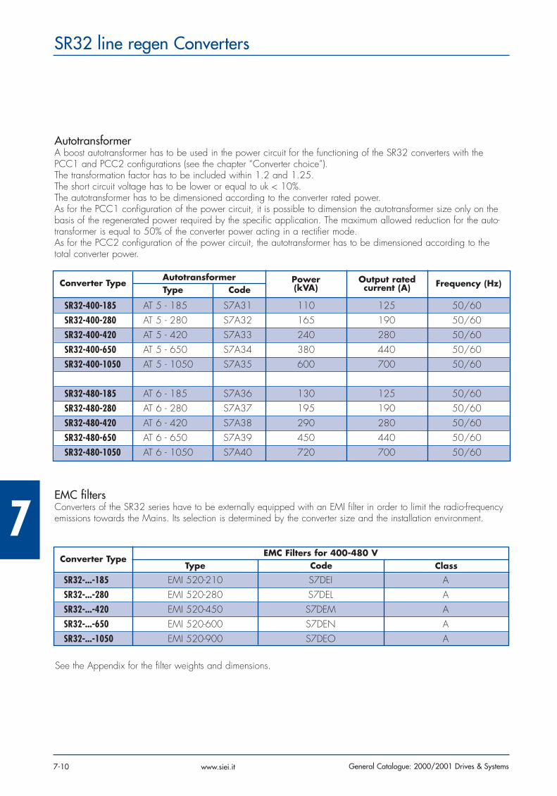
AutotransformerA boost autotransformer has to be used in the power circuit for the functioning of the SR32 converters with thePCC1 and PCC2 configurations (see the chapter “Converter choice”).The transformation factor has to be included within 1.2 and 1.25.The short circuit voltage has to be lower or equal to uk < 10%.The autotransformer has to be dimensioned according to the converter rated power.As for the PCC1 configuration of the power circuit, it is possible to dimension the autotransformer size only on thebasis of the regenerated power required by the specific application. The maximum allowed reduction for the auto-transformer is equal to 50% of the converter power acting in a rectifier mode.As for the PCC2 configuration of the power circuit, the autotransformer has to be dimensioned according to thetotal converter power.
SR32-400-185 AT 5 - 185 S7A31 110 125 50/60SR32-400-280 AT 5 - 280 S7A32 165 190 50/60SR32-400-420 AT 5 - 420 S7A33 240 280 50/60SR32-400-650 AT 5 - 650 S7A34 380 440 50/60SR32-400-1050 AT 5 - 1050 S7A35 600 700 50/60
SR32-480-185 AT 6 - 185 S7A36 130 125 50/60SR32-480-280 AT 6 - 280 S7A37 195 190 50/60SR32-480-420 AT 6 - 420 S7A38 290 280 50/60SR32-480-650 AT 6 - 650 S7A39 450 440 50/60SR32-480-1050 AT 6 - 1050 S7A40 720 700 50/60
Converter TypeAutotransformerType Code
Power(kVA)
Output rated current (A) Frequency (Hz)
EMC filtersConverters of the SR32 series have to be externally equipped with an EMI filter in order to limit the radio-frequencyemissions towards the Mains. Its selection is determined by the converter size and the installation environment.
SR32-...-185 EMI 520-210 S7DEI ASR32-...-280 EMI 520-280 S7DEL ASR32-...-420 EMI 520-450 S7DEM ASR32-...-650 EMI 520-600 S7DEN ASR32-...-1050 EMI 520-900 S7DEO A
Converter TypeEMC Filters for 400-480 V
Type Code Class
See the Appendix for the filter weights and dimensions.

7
7-11General Catalogue: 2000/2001 Drives & Systems
SR32 line regen Converters
www.siei.it
Field Bus cardsAllow connections to Field Buses such as Profibus-DP and Interbus-S.
S5H47 SBI-PDP-32 Profibus_DP interface
S5N80 SBI-SL-D32 Interbus_S interface
KB programming keypadIt allows the converter configuration without using a PC. Converter enabling, disabling, start/stop, control and confi-guration via a keypad with a 2-line display which is backlighted by liquid crystals.
S5P2U KB - SR32 Programming keypad
Others
S51VV Kit for remote keypad Kit for a remotable setting of KB keypads or KC LED modules
S5Z40 A-RS485 External power supply for the RS485 serial line
S546Z PCI-485 RS232/RS485 serial interface
8S8F59 Shielded cable for PCI 485 RS485 serial interface cable (length: 5 meters)
S5QQ1 RS485 kit Serial Adapter RS485 serial line kit (PCI 485+connection cable)
7
General Catalogue: 2000/2001 Drives & Systems7-12
SR32 line regen Converters
www.siei.it


