
82551QM/82540EM Interchangeable LOM Design GuideApplication Note (AP-432)
December 2003
Revision 1.0

ii Application Note (AP-432)
82551QM/82540EM Interchangeable LOM Design Guide
Information in this document is provided in connection with Intel® products. No license, express or implied, by estoppel or otherwise, to any intellectual property rights is granted by this document. Except as provided in Intel's Terms and Conditions of Sale for such products, Intel assumes no liability whatsoever, and Intel disclaims any express or implied warranty, relating to sale and/or use of Intel products including liability or warranties relating to fitness for a particular purpose, merchantability, or infringement of any patent, copyright or other intellectual property right. Intel products are not intended for use in medical, life saving, or life sustaining applications.
Intel may make changes to specifications and product descriptions at any time, without notice.
The NAME OF PRODUCT may contain design defects or errors known as errata which may cause the product to deviate from published specifications. Current characterized errata are available on request.
This document and the software described in it are furnished under license and may only be used or copied in accordance with the terms of the license. The information in this document is furnished for informational use only, is subject to change without notice, and should not be construed as a commitment by Intel Corporation. Intel Corporation assumes no responsibility or liability for any errors or inaccuracies that may appear in this document or any software that may be provided in association with this document. Except as permitted by such license, no part of this document may be reproduced, stored in a retrieval system, or transmitted in any form or by any means without the express written consent of Intel Corporation.
Contact your local Intel sales office or your distributor to obtain the latest specifications and before placing your product order.
Copies of documents which have an ordering number and are referenced in this document or other Intel literature may be obtained by calling 1-800-548-4725 or by visiting Intel's website at http://www.intel.com.
Copyright © 2003, Intel Corporation.
* Third party Other names and brands may be claimed as the property of others.

82551QM/82540EM Interchangeable LOM Design Guide
Revision History
Date Revision Description
Dec 2003 1.0 Initial public release. (Confidential status was removed.)
Application Note (AP-432) iii

82551QM/82540EM Interchangeable LOM Design Guide
iv Application Note

82551QM/82540EM Interchangeable LOM Design Guide
Contents1.0 Introduction....................................................................................................................................1
1.1 Document Scope ..................................................................................................................11.2 Reference Documents ..........................................................................................................11.3 Product Code........................................................................................................................2
2.0 Pin Number to Signal Mapping ....................................................................................................2
3.0 Gigabit Ethernet Design................................................................................................................9
4.0 Reference Schematic ....................................................................................................................9
Application Note (AP-432) v

82551QM/82540EM Interchangeable LOM Design Guide
vi Application Note

82551QM/82540EM Interchangeable LOM Design Guide
1.0 Introduction
The Intel® 82540EM Gigabit Ethernet Controller and the Intel® 82551QM Fast Ethernet Controller are both manufactured in a footprint compatible 15 mm x 15 mm, 196-Ball Grid Array (BGA) package. Many of the critical signal pin locations on the 82540EM are identical to signals on the 82551QM, allowing designers to create a single design that accommodates both parts. However, the usage of some signals and pins differ between the two devices. Thus, they are not referred to as pin compatible. They are footprint compatible, which means that they share the same package size and the same number and pattern of pins, allowing the signal layout to be flexible and cost effective and to be used as a multipurpose design. This enables a single board design for either device maximizing its value and matching performance needs.
This design is also backwards compatible with the 82559 and 82550 controllers. Engineers with experience implementing these previous generations of Intel Fast Ethernet controllers can easily and confidently update older designs or modify those designs enabling upgrades for the 82540EM Gigabit Ethernet Controller to meet customer requirements while minimizing design variables.
Note: The 82559 and 82550 designs are not forward compatible to this design. Support for features such as IP Security, Alert Standard Format, and Alert on Lan*, is dependant on the feature set of the controller, which is detailed in the device product brief or datasheet. These documents should be referenced to better understand the capabilities of the device selected for a design.
1.1 Document Scope
This application note identifies the design differences between the 82540EM and the 82551QM.
Section 2.0, “Pin Number to Signal Mapping,” contains a table summarizing the population options for both devices, and a reference schematic is contained in Section 4.0, “Reference Schematic.”
1.2 Reference Documents
It is assumed that the designer is acquainted with high-speed design and board layout techniques. The following documents provide additional information:
• Intel® 82551QM Fast Ethernet Multifunction PCI/CardBus Controller Datasheet, Intel Corporation.
• Intel® 82540EM Gigabit Ethernet Controller Datasheet, Intel Corporation.
• PCI Local Bus Specification, Revision 2.2, PCI Special Interest Group.
• PCI Bus Power Management Interface Specification, Rev. 1.1, PCI Special Interest Group.
• IEEE Standard 802.3, 1996 Edition, Institute of Electrical and Electronics Engineers (IEEE).
• IEEE Standard 802.3u, 1995 Edition, Institute of Electrical and Electronics Engineers (IEEE).
• IEEE Standard 802.3x, 1997 Edition, Institute of Electrical and Electronics Engineers (IEEE).
• IEEE Standard 802.3z, 1998 Edition, Institute of Electrical and Electronics Engineers (IEEE).
• IEEE Standard 802.3ab, 1999 Edition, Institute of Electrical and Electronics Engineers (IEEE).
• Intel® Ethernet Controllers Timing Device Selection Guide, AP-419. Intel Corporation.
Application Note (AP-432) 1

82551QM/82540EM Interchangeable LOM Design Guide
1.3 Product Code
The product ordering code for the 82551QM is: GD82551QM.
The product ordering code for the 82540EM is: RC82540EM.
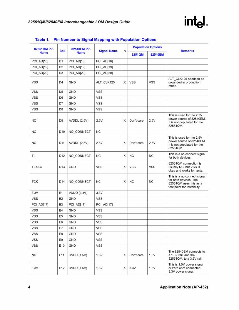
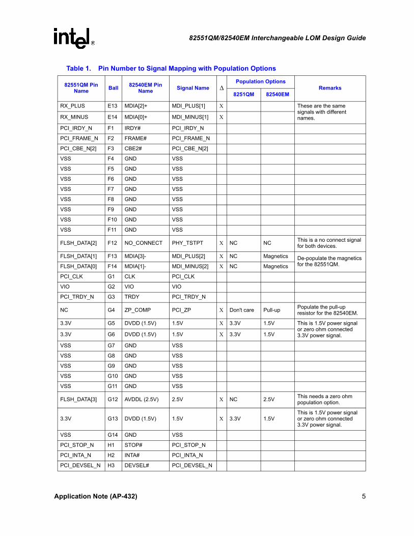
2.0 Pin Number to Signal Mapping
The table below shows the pin names for each controller corresponding to the shared ball reference value.
Note: The 82540EM pin names in this table and reference schematic found at the end of this document may differ slightly from the pin names in the datasheet. The datasheet signal names maintain consistency with the 64-bit gigabit controller naming convention, while the reference schematics follow the convention used by our engineers on their design tools.
Table 1. Pin Number to Signal Mapping with Population Options
82551QM Pin Name Ball 82540EM Pin
Name Signal Name ∆Population Options
Remarks8251QM 82540EM
NC A1 NO_CONNECT NC
PCI_SERR_N A2 SERR# PCI_SERR_N
3.3V A3 VDDO (3.3V) 3.3V
PCI_IDSEL A4 IDSEL PCI_IDSEL
PCI_AD[25] A5 PCI_AD[25] PCI_AD[25]
PCI_PME_N A6 PME# PCI_PME_N
3.3V A7 VDDO (3.3V) 3.3V
PCI_AD[30] A8 PCI_AD[30] PCI_AD[30]
ALT_RST_N A9 LAN_PWR_ GOOD
LAN_PWR_ GOOD Χ
Pull-up or Master Reset
Master Reset
Master chip reset for both; 82551QM can be pulled up and use an internal reset.
SMB_CLK A10 SMBCLK SMB_CLK
3.3V A11 VDDO (3.3V) 3.3V
LINK_LED A12 LINKA# LINK_UP_N Χ These are the same. They just use different names.
TEST A13 TEST TEST_MAC_DM Χ Pull-down Pull-downThis is a test enable signal. Both require an external pull-down resistor.
NC A14 NO_CONNECT NC
PCI_AD[22] B1 PCI_AD[22] PCI_AD[22]
PCI_AD[23] B2 PCI_AD[23] PCI_AD[23]
VSS B3 GND VSS
PCI_AD[24] B4 PCI_AD[24] PCI_AD[24]
PCI_AD[26] B5 PCI_AD[26] PCI_AD[26]
2 Application Note (AP-432)

82551QM/82540EM Interchangeable LOM Design Guide
PCI_AD[27] B6 PCI_AD[27] PCI_AD[27]
VSS B7 GND VSS
PCI_AD[31] B8 PCI_AD[31] PCI_AD[31]
ISOLATE_N B9 RST# PCI_RST_N ΧThese are the same. ISOLATE_N is used as PCI_RST_N.
SMB_ALERT_N B10 SMBALRT# SMB_ALERT_N
SPEED_LED B11 LINKA100# LINK100_N ΧThese signals have the exact same functionality but use different names.
TO B12 LINKA1000# LINK1000_N Χ NC LED LINK1000 LED does not exist in the 82551QM.
RBIAS100 B13 CTRL_25 CTRL_25 Χ619 Ω pull-down resistor
Power Regulator
Populate the 82551QM design with a pull-down and the 82540EM with a transistor.
RBIAS10 B14 PHY REF PHY REF Χ 549 Ω pull-down
2.49 KΩ pull-down
Change the value of the pull-down resistor for each option.
PCI_AD[21] C1 PCI_AD[21] PCI_AD[21]
PCI_RST_N C2 M66EN M66EN Χ Pull-up PCI M66ENThis may require zero ohm resistors to a M66EN signal.
PCI_REQ_N C3 REQ# PCI_REQ_N
PCI_CBE_N[3] C4 CBE3# PCI_CBE_N[3]
CSTCHG C5 APM_WAKEUP APM_WAKEUP ΧThese signals are the same but have different names.
PCI_AD[28] C6 PCI_AD[28] PCI_AD[28]
PCI_AD[29] C7 PCI_AD[29] PCI_AD[29]
CLK_RUN_N C8 NO_CONNECT NC Χ Pull-down Don't care
The pull-down resistor for the 82551QM can be left alone or depopulated for the 82540EM.
SMB_DAT C9 SMBDAT SMB_DAT
VSS C10 GND VSS
ACT_LED C11 ACT_A# ACTIVITY_N ΧThese signals are the same but have different names.
VREF C12 GND VSS Χ VSS VSS
The 82551QM connection is usually NC (it has an internal pull-down), but VSS is okay.
TX_PLUS C13 MDIA[2]- MDI_PLUS[0] Χ These signals are the same but have different names.TX_MINUS C14 MDIA[0]- MDI_MINUS[0] Χ
Table 1. Pin Number to Signal Mapping with Population Options
82551QM Pin Name Ball 82540EM Pin
Name Signal Name ∆Population Options
Remarks8251QM 82540EM
Application Note (AP-432) 3
82551QM/82540EM Interchangeable LOM Design Guide
PCI_AD[18] D1 PCI_AD[18] PCI_AD[18]
PCI_AD[19] D2 PCI_AD[19] PCI_AD[19]
PCI_AD[20] D3 PCI_AD[20] PCI_AD[20]
VSS D4 GND ALT_CLK125 Χ VSS VSSALT_CLK125 needs to be grounded in production mode.
VSS D5 GND VSS
VSS D6 GND VSS
VSS D7 GND VSS
VSS D8 GND VSS
NC D9 AVDDL (2.5V) 2.5V Χ Don't care 2.5V
This is used for the 2.5V power source of 82540EM. It is not populated for the 82551QM.
NC D10 NO_CONNECT NC
NC D11 AVDDL (2.5V) 2.5V Χ Don't care 2.5V
This is used for the 2.5V power source of 82540EM. It is not populated for the 82551QM.
TI D12 NO_CONNECT NC Χ NC NC This is a no connect signal for both devices.
TEXEC D13 GND VSS Χ VSS VSS82551QM connection is usually NC, but VSS is okay and works for tests.
TCK D14 NO_CONNECT NC Χ NC NC
This is a no connect signal for both devices. The 82551QM uses this as a test point for testability.
3.3V E1 VDDO (3.3V) 3.3V
VSS E2 GND VSS
PCI_AD[17] E3 PCI_AD[17] PCI_AD[17]
VSS E4 GND VSS
VSS E5 GND VSS
VSS E6 GND VSS
VSS E7 GND VSS
VSS E8 GND VSS
VSS E9 GND VSS
VSS E10 GND VSS
NC E11 DVDD (1.5V) 1.5V Χ Don't care 1.5VThe 82540EM connects to a 1.5V rail, and the 82551QM, to a 3.3V rail.
3.3V E12 DVDD (1.5V) 1.5V Χ 3.3V 1.5VThis is 1.5V power signal or zero ohm connected 3.3V power signal.
Table 1. Pin Number to Signal Mapping with Population Options
82551QM Pin Name Ball 82540EM Pin
Name Signal Name ∆Population Options
Remarks8251QM 82540EM
4 Application Note (AP-432)
82551QM/82540EM Interchangeable LOM Design Guide
RX_PLUS E13 MDIA[2]+ MDI_PLUS[1] Χ These are the same signals with different names.RX_MINUS E14 MDIA[0]+ MDI_MINUS[1] Χ
PCI_IRDY_N F1 IRDY# PCI_IRDY_N
PCI_FRAME_N F2 FRAME# PCI_FRAME_N
PCI_CBE_N[2] F3 CBE2# PCI_CBE_N[2]
VSS F4 GND VSS
VSS F5 GND VSS
VSS F6 GND VSS
VSS F7 GND VSS
VSS F8 GND VSS
VSS F9 GND VSS
VSS F10 GND VSS
VSS F11 GND VSS
FLSH_DATA[2] F12 NO_CONNECT PHY_TSTPT Χ NC NC This is a no connect signal for both devices.
FLSH_DATA[1] F13 MDIA[3]- MDI_PLUS[2] Χ NC Magnetics De-populate the magnetics for the 82551QM.FLSH_DATA[0] F14 MDIA[1]- MDI_MINUS[2] Χ NC Magnetics
PCI_CLK G1 CLK PCI_CLK
VIO G2 VIO VIO
PCI_TRDY_N G3 TRDY PCI_TRDY_N
NC G4 ZP_COMP PCI_ZP Χ Don't care Pull-up Populate the pull-up resistor for the 82540EM.
3.3V G5 DVDD (1.5V) 1.5V Χ 3.3V 1.5V This is 1.5V power signal or zero ohm connected 3.3V power signal.3.3V G6 DVDD (1.5V) 1.5V Χ 3.3V 1.5V
VSS G7 GND VSS
VSS G8 GND VSS
VSS G9 GND VSS
VSS G10 GND VSS
VSS G11 GND VSS
FLSH_DATA[3] G12 AVDDL (2.5V) 2.5V Χ NC 2.5V This needs a zero ohm population option.
3.3V G13 DVDD (1.5V) 1.5V Χ 3.3V 1.5VThis is 1.5V power signal or zero ohm connected 3.3V power signal.
VSS G14 GND VSS
PCI_STOP_N H1 STOP# PCI_STOP_N
PCI_INTA_N H2 INTA# PCI_INTA_N
PCI_DEVSEL_N H3 DEVSEL# PCI_DEVSEL_N
Table 1. Pin Number to Signal Mapping with Population Options
82551QM Pin Name Ball 82540EM Pin
Name Signal Name ∆Population Options
Remarks8251QM 82540EM
Application Note (AP-432) 5

82551QM/82540EM Interchangeable LOM Design Guide
NC H4 ZN_COMP PCI_ZN Χ Don't care Pull-down Populate the pull-down resistor for the 82540EM.
3.3V H5 DVDD (1.5V) 1.5V Χ 3.3V 1.5V
This is 1.5V power signal or zero ohm connected 3.3V power signal.
3.3V H6 DVDD (1.5V) 1.5V Χ 3.3V 1.5V
3.3V H7 DVDD (1.5V) 1.5V Χ 3.3V 1.5V
3.3V H8 DVDD (1.5V) 1.5V Χ 3.3V 1.5V
VSS H9 GND VSS
VSS H10 GND VSS
NC H11 DVDD (1.5V) 1.5V Χ Don't care 1.5VThe 82540EM connects to a 1.5V rail, and the 82551QM, to a 3.3V rail.
FLSH_DATA[6] H12 NO_CONNECT HSDACN Χ NC NC This is a no connect signal for both devices.
FLSH_DATA[5] H13 MDIA[3]+ MDI_PLUS[3] Χ NC Magnetics De-populate the magnetics for the 82551QM.FLSH_DATA[4] H14 MDIA[1]+ MDI_MINUS[3] Χ NC Magnetics
PCI_PAR J1 PAR PCI_PAR
PCI_PERR_N J2 PERR# PCI_PERR_N
PCI_GNT_N J3 GNT# PCI_GNT_N
NC J4 NO_CONNECT NC
3.3V J5 DVDD (1.5V) 1.5V Χ 3.3V 1.5V
This is 1.5V power signal or zero ohm connected 3.3V power signal.
3.3V J6 DVDD (1.5V) 1.5V Χ 3.3V 1.5V
3.3V J7 DVDD (1.5V) 1.5V Χ 3.3V 1.5V
3.3V J8 DVDD (1.5V) 1.5V Χ 3.3V 1.5V
3.3V J9 DVDD (1.5V) 1.5V Χ 3.3V 1.5V
3.3V J10 DVDD (1.5V) 1.5V Χ 3.3V 1.5V
3.3V J11 DVDD (1.5V) 1.5V Χ 3.3V 1.5V
FLSH_ADDR[1] J12 AUX_PWR AUX_PWR Χ
These are the same. 82551QM FLA[1] signal samples auxiliary power at reset. 82540EM always samples auxiliary power.
FLSH_ADDR[0] J13 NO_CONNECT HSDACP Χ NC NC This can be no connect for both devices.
FLSH_DATA[7] J14 XTAL2 XTAL2 Χ NC XTAL2 These signals need a zero ohm population option.
PCI_AD[16] K1 PCI_AD[16] PCI_AD[16]
VSS K2 GND VSS
3.3V K3 VDDO (3.3V) 3.3V
3.3V K4 VDDO (3.3V) 3.3V
Table 1. Pin Number to Signal Mapping with Population Options
82551QM Pin Name Ball 82540EM Pin
Name Signal Name ∆Population Options
Remarks8251QM 82540EM
6 Application Note (AP-432)

82551QM/82540EM Interchangeable LOM Design Guide
3.3V K5 DVDD (1.5V) 1.5V Χ 3.3V 1.5V
This is 1.5V power signal or zero ohm connected 3.3V power signal.
3.3V K6 DVDD (1.5V) 1.5V Χ 3.3V 1.5V
3.3V K7 DVDD (1.5V) 1.5V Χ 3.3V 1.5V
3.3V K8 DVDD (1.5V) 1.5V Χ 3.3V 1.5V
3.3V K9 DVDD (1.5V) 1.5V Χ 3.3V 1.5V
3.3V K10 DVDD (1.5V) 1.5V Χ 3.3V 1.5V
3.3V K11 DVDD (1.5V) 1.5V Χ 3.3V 1.5V
VSS K12 GND VSS
3.3V K13 VDDO (3.3V) 3.3V
FLSH_ADDR[2] K14 XTAL1 XTAL1 Χ NC XTAL1 These pins require a zero ohm population option.
PCI_AD[14] L1 PCI_AD[14] PCI_AD[14]
PCI_AD[15] L2 PCI_AD[15] PCI_AD[15]
PCI_CBE_N[1] L3 CBE1# PCI_CBE_N[1]
3.3V L4 DVDD (1.5V) 1.5V Χ 3.3V 1.5V This is 1.5V power signal or zero ohm connected 3.3V power signal.3.3V L5 DVDD (1.5V) 1.5V Χ 3.3V 1.5V
VSS L6 GND VSS
MODEM_CS_N L7 NO_CONNECT CLK_BYP_N Χ NC NC No connect.
NC L8 AVDDL (2.5V) 2.5V Χ Don't care 2.5V
This is the 2.5V power source for the 82540EM. It is not populated for the 82551QM.
3.3V L9 DVDD (1.5V) 1.5V Χ 3.3V 1.5V This is 1.5V power signal or zero ohm connected 3.3V power signal.3.3V L10 DVDD (1.5V) 1.5V Χ 3.3V 1.5V
VSS L11 GND VSS
FLSH_ADDR[5] L12 JTAG_TMS JTAG_TMS Χ NC JTAGDe-populate any JTAG passive or active logic in the 82551QM.
FLSH_ADDR[4] L13 JTAG_TRST# JTAG_TRST_N Χ NC JTAG
FLSH_ADDR[3] L14 JTAG_TCK JTAG_TCK Χ NC JTAG
PCI_AD[11] M1 PCI_AD[11] PCI_AD[11]
PCI_AD[12] M2 PCI_AD[12] PCI_AD[12]
PCI_AD[13] M3 PCI_AD[13] PCI_AD[13]
PCI_CBE_N[0] M4 CBE0# PCI_CBE_N[0]
PCI_AD[5] M5 PCI_AD[5] PCI_AD[5]
VSS M6 GND VSS
PCI_AD[1] M7 PCI_AD[1] PCI_AD[1]
FLSH_OE_N M8 CLK_VIEW CLK_VIEW Χ NC NC No connect.
FLSH_WE_N M9 NO_CONNECT FLSH_CE_N Χ NC NC No connect.
Table 1. Pin Number to Signal Mapping with Population Options
82551QM Pin Name Ball 82540EM Pin
Name Signal Name ∆Population Options
Remarks8251QM 82540EM
Application Note (AP-432) 7

82551QM/82540EM Interchangeable LOM Design Guide
FLSH_ADDR[15]/EESK M10 EE_SK EESK Χ
These are the same signals but have different names.
FLSH_ADDR[12] M11 NO_CONNECT FLSH_SI Χ NC NC No connect.
FLSH_ADDR[11] M12 SDP[7] SDP[7] Χ NC SDP De-populate any SDP logic with the 82551QM.
FLSH_ADDR[7] M13 JTAG_TDI JTAG_TDI Χ NC JTAG De-populate any JTAG passive or active logic in the 82551QM.FLSH_ADDR[6] M14 JTAG_TDO JTAG_TDO Χ NC JTAG
VSS N1 GND VSS
PCI_AD[10] N2 PCI_AD[10] PCI_AD[10]
PCI_AD[9] N3 PCI_AD[9] PCI_AD[9]
PCI_AD[7] N4 PCI_AD[7] PCI_AD[7]
PCI_AD[4] N5 PCI_AD[4] PCI_AD[4]
3.3V N6 VDDO (3.3V) 3.3V
PCI_AD[0] N7 PCI_AD[0] PCI_AD[0]
3.3V N8 VDDO (3.3V) 3.3V
FLSH_CE_N N9 NO_CONNECT FLSH_SCK Χ NC NC No connect.
FLSH_ADDR[14]/EEDO N10 EE_DO EE_DO Χ
These are the same signals but have different names.
XTAL1 N11 NO_CONNECT NC Χ XTAL Don't care These require a zero ohm population option.
VSS N12 GND VSS
FLSH_ADDR[10] N13 SDP[6] SDP[6] Χ NC SDPDe-populate any SDP logic with the 82551QM.FLSH_ADDR[8]
/IOCHRDY N14 SDP[0] SDP[0] Χ NC SDP
NC P1 NO_CONNECT NC
3.3V P2 VDDO (3.3V) 3.3V
PCI_AD[8] P3 PCI_AD[8] PCI_AD[8]
PCI_AD[6] P4 PCI_AD[6] PCI_AD[6]
PCI_AD[3] P5 PCI_AD[3] PCI_AD[3]
PCI_AD[2] P6 PCI_AD[2] PCI_AD[2]
EE_CS P7 EE_CS EE_CS
VSS P8 GND VSS
FLSH_ADDR[16] P9 NO_CONNECT FLSH_SO Χ NC NC No connect.
FLSH_ADDR[13]/EEDI P10 EE_DI EE_DI Χ
These are the same signals but have different names.
XTAL2 P11 CTRL_15 CTRL_15 Χ XTAL Power Regulator
These require a zero ohm population option.
Table 1. Pin Number to Signal Mapping with Population Options
82551QM Pin Name Ball 82540EM Pin
Name Signal Name ∆Population Options
Remarks8251QM 82540EM
8 Application Note (AP-432)

82551QM/82540EM Interchangeable LOM Design Guide
3.0 Gigabit Ethernet Design
The 82540EM Gigabit Ethernet Controller Datasheet provides information relating to design considerations specific to Gigabit Ethernet. Fast Ethernet and Gigabit Ethernet designs share many of the same requirements. The primary differences between Fast Ethernet and Gigabit Ethernet designs are:
• The increased number of traces from the device PHY unit. Gigabit Ethernet requires 8 traces, and Fast Ethernet, 4 traces.
• Tighter signaling characteristics for Gigabit Ethernet.
4.0 Reference Schematic
The following pages illustrate a dual purpose Fast Ethernet and Gigabit Ethernet design using the 82551QM and 82540EM controllers.
Note: The 82540EM pin names in the reference schematic found at the end of this document may differ slightly from the pin names in the datasheet. The datasheet signal names maintain consistency with the 64-bit gigabit controller naming convention, while the reference schematics follow the convention used by our engineers on their design tools.
3.3V P12 VDDO (3.3V) 3.3V
FLSH_ADDR[9] P13 SDP[1] SDP[1] Χ NC NC De-populate any SDP logic with 82551QM.
NC P14 NO_CONNECT NC
Table 1. Pin Number to Signal Mapping with Population Options
82551QM Pin Name Ball 82540EM Pin
Name Signal Name ∆Population Options
Remarks8251QM 82540EM
Application Note (AP-432) 9

82551QM/82540EM Interchangeable LOM Design Guide
Fo
r 8
25
40
EP
de
sig
ns,
Ball
C5
is
a N
C p
in
int
le
R
1m
m P
itch
15
mm
x 1
5m
m B
GA
Pin
Nam
e D
ec
od
e =
LA
VO
N S
ign
al N
am
e −
KE
NA
I32
Sig
nal
Nam
e
LA
VO
N/K
EN
AI32
Com
bo S
ym
bol
10/10
0/1
000
Mbp
s
Eth
ern
et
Co
ntr
oller
No
te:
Fo
r 8
25
40
EP
de
sig
ns,
ba
ll C
8 i
s a
CL
KR
UN
# p
inan
d i
s ro
ute
d t
oa
co
ntr
ol
lin
e
on
th
e s
yste
m
82
55
1
Som
e E
Epro
m m
anufa
cture
sm
ay
require a
pull-
up
resist
or o
n p
in 6
.
Ensu
re that th
e S
MBD a
nd S
MBCLK
trace
s are
pulle
d to lo
gic
hig
h w
ith
weak
pullu
p resist
ors
som
ewhere
on
the N
IC o
r pla
nar.
82
55
1
Pla
ce th
is c
ap c
lose
to th
is E
EP
RO
M
82
55
18
25
51
82
55
1/8
25
40
82
55
1
82
54
0
82
55
1
= In
sta
ll c
om
po
nen
t if
usi
ng
KE
NA
I M
AC
/P
HY
= In
sta
ll c
om
po
ne
nt
if u
sin
g L
AV
ON
MA
C/
PH
Y
825
51
/82
540
IN
TE
RFA
CE
8254
0-82
551
RE
F. D
ES
IGN
1.5
v Rail
only
required
with 8
2540 C
ontrolle
r2.5
v Rail
only
required
with 8
2540 C
ontrolle
r.Not co
nnect
ed w
ith 8
2551
Fo
r R
6:
Inst
all
54
9 o
hm
re
sist
or
(1%
) w
ith
82
55
1
Co
ntr
oll
er
or
2.4
9K
oh
m r
esis
tor
(1%
) w
ith
82
54
0 C
on
tro
lle
r.
Ro
ute
to
Pw
r M
gm
t lo
gic
Ro
ute
to
JTA
G l
og
ic
82
54
0
82
54
0
82
54
0
82
54
0
82
54
08
25
40
If the P
CI bus
segm
ent
is n
ot ca
pable
of >
33M
hz
opera
tion the M
66EN
signal sh
ould
be p
ulle
dto
a logic low b
y th
e N
ICor pla
nar.
Use
SM
T 0
805 s
ize
resist
or fo
r R1
10 Application Note (AP-432)

82551QM/82540EM Interchangeable LOM Design Guide
RTermination
RTermination
RTermination
RTermination
RJ4
5-8
RJ4
5-7
RJ4
5-5
RJ4
5-4
RJ4
5-6
RJ4
5-3
RJ4
5-2
RJ4
5-1
82
55
1
82
54
0
82540/82551
82540/82551
Thes
e th
ree
capa
cito
rsac
ross
the
CH
AS
SIS
_GN
Dto
GN
D s
plit,
are
loca
ted
belo
wth
e m
agne
tics
mod
ule.
Pla
ce
as c
lose
as
poss
ible
to th
e m
agne
tics
mod
ule.
The
se th
ree
capa
cito
rsac
ross
the
CH
AS
SIS
_GN
Dto
GN
D s
plit,
are
loca
ted
abov
eth
e m
agne
tics
mod
ule.
Pla
ce
as c
lose
as
poss
ible
to th
e m
agne
tics
mod
ule.
KE
NA
I32-
LAV
ON
RE
F. D
ES
IGN
BI-
CO
LO
R S
PE
ED
LE
D
LIN
K/
AC
TIV
ITY
LE
D
10
/1
00
/1
00
0 P
HY
IN
TE
RFA
CE
wit
h I
nte
gra
de
d M
ag
ne
tic
s &
RJ4
5
82
54
0
82
54
0
82
54
08
25
40
82
54
08
25
40
82
54
0
82
54
0
82
54
08
25
40
82
54
0
82
54
08
25
40
Fo
r R
10
5 a
nd
R1
14
:
I
nsta
ll 1
% 4
9 o
hm
r
esis
tors w
ith
82
54
0
o
r 1
% 6
0.4
oh
m r
esis
tors
w
ith
a 8
25
51
co
ntro
lle
r.
82540/82551
82540/82551
82540/82551
Application Note (AP-432) 11

82551QM/82540EM Interchangeable LOM Design Guide
82
54
0
82
54
0
82
54
0
82
54
0
82
54
0
82
54
0/8
25
51
VC
C3
.3v
De
co
up
lin
g C
ap
s
2.5
V &
1.5
V P
OW
ER
RE
GU
LA
TIO
N
LE
D &
CR
YS
TA
L C
IR
CU
IT
S
Insta
ll p
ow
er
transis
tors
Q1 &
Q2 a
nd s
upport
com
ponents
only
when u
sin
g 8
2540 C
ontr
oller.
This
dev
ice
shou
ld b
e pl
aced
as
clos
e as
po
ssib
leto
the
crys
tal i
nput
pin
s of
the
825
40 E
ther
net
Con
trol
ler.
Kee
p tr
aces
sho
rt a
s po
ssib
le8
25
51
82
55
1
DS
1
LIN
K/
AC
TIV
IT
Y L
ED
DS
2 B
I-C
OL
OR
SP
EE
D L
ED
8254
0-82
551
RE
F. D
SG
N
82
55
1
=
Inst
all
co
mp
on
en
t if
usi
ng
82
54
0 M
AC
/P
HY
=
Inst
all
co
mp
on
en
t if
usi
ng
82
55
1 M
AC
/P
HY
Layout m
ay
require
multip
le resist
ors
in
para
llel here
for pro
per
pow
er disapation.
12 Application Note (AP-432)

82551QM/82540EM Interchangeable LOM Design Guide
PC
I IN
TE
RFA
CE
(la
yo
ut a
id o
nly
)
Application Note (AP-432) 13


