
The Southern African Institute of Mining and Metallurgy
Platinum 2012
65
D. Nardini, M. Andrews, G. Brooks
A conceptual study into optimizing the delivery of trackbound twin ends
through trackless mechanized development
D. Nardini Sandvik Mining
M. Andrews Sandvik Mining
G. Brooks Sandvik Mining
Abstract
The need to move towards faster and safer mine development is a key priority in mining houses
globally. In addition to this, South Africa faces an array of challenges introduced by labour-
intensive operations; hence a study was conducted to look into improving development rates
and labour productivity, specifically in the areas where trackbound flat-end development is
required. The aim of the study was to propose a method to deliver fit-for-purpose tracked
tunnels that advanced at a rate of one blast per end every single working day. A major part of
the study was to optimize the selection of an appropriate trackless fleet and mitigate any
constraints introduced with the mechanization. This was done by creating scenarios, based on a
typical case study, looking into the aspects around safety, mine design, mine activity cycling,
men and machine requirements, service installations, and trackless-trackbound interfaces. The
case study was based on a deep-level gold mine developing twin headings with connectings;
however, with the move to extend and deepen platinum operations it is foreseen that twin end
development will become more prevalent due to ventilation, logistical, and other requirements.
With the introduction of the trackless mechanized system suggested, development rates of 56
m of system advance are expected (189 m total development), with on an average of three
headings and fixed blast times. Scenarios run with multi-blast conditions yield expectations of
75 m/month advance of the system, significantly higher than the conventional performance
seen today.
Introduction
The need to increase development rates is not a new challenge, and the benefits from higher
development rates are both financial (with a better NPV result) and operational (allowing more
flexibility). Additionally, the single biggest barrier to achieving mine call is insufficient face
availability; higher rates of development would mitigate this problem. Typically mining activities
in conventional mines have been evolving for decades, and development rate and stoping rate
were matched to optimize production. However, with more labour and safety constraints,
performance has progressively deteriorated.

The Southern African Institute of Mining and Metallurgy
Platinum 2012
66
A step change is needed to achieve the results that the mining houses are now striving towards.
It is perceived that this can be achieved through the introduction of a trackless system
employing mechanized equipment and ways of working.
Blast rounds in conventional mining are limited by the ability of operators to accurately drill
blastholes with hand-held rockdrills. Mechanized drill rigs enable mines to drill longer and more
accurate rounds and thus achieve higher rates of advance per blast. More advance means more
rock to clean and more support to install. All activities are increased but need to be completed
in the available time.
The introduction of trackless mechanized machinery into South African mining operations has
been slow and marred by many challenges and setbacks. The focus on safety is a top priority,
and mines are looking for ways to remove men from the face and other dangerous working
areas.
Additionally, the mine design and its supporting infrastructure is based on trackbound
machinery and hand-held equipment. As a result, trackbound mines have been slow to adopt
new technology available through trackless machinery. The challenge explored in this paper is
how to integrate trackless mechanized mining at a higher rate than conventional mining with
operational trackbound rock transport systems.
In small single-end development, trackless equipment has limited application, there is just no
space for different pieces of equipment to pass each other, to be parked or maintained.
Typically the deep-level gold mines employ the twin-end trackbound development designs.
With the platinum mines progressing deeper, the need for twin-end flat development is
foreseen to be more widely adopted due to ventilation requirements, man and material
transport, safety aspects, and the need to mechanize.
To this end Sandvik has looked into a conceptual study of a mechanized fleet of trackless
equipment for flat twin-end development supporting trackbound machinery for production.
The study was based on an actual case study from a deep-level gold mine. This paper discusses
the details and benefits of such a system, with the aim of applying the lessons learned to future
platinum mines. Understandably, the challenge remains in implementing such a change both in
an operating mine with an established way of working and to new operations resistant to
change.

The Southern African Institute of Mining and Metallurgy
Platinum 2012
67
Objectives
The objective of the case study was to evaluate a new approach to ‘fit-for purpose’ level
development of rail/trackbound mines to realize, amongst others, production and safety
benefits.
• First and foremost, safety on mines is not only a strategic objective but impacts
operations on a frequent basis. The study recognized an array of safety benefits with the
introduction of the trackless machines on the case study site
• The system objective was set to achieve one blast per end per day. This entailed the
two twin ends as a priority, the footwall (FWD) drive and return airway (RAW), and
either the crosscut to the orebody or the connectings
• With further mechanization, the labour productivity is expected to increase, allowing
mining houses to better utilize their resources. This aspect is becoming more of a
concern with the availability of skilled personnel and more importantly the willingness
of people to work in such environments.
Methodology
Based on site studies, information, and observations the following fundamentals were used as a
basis for evaluating and selecting the optimal mining system:
• the mine design
• resources (machines, people, time)
• the mining process.
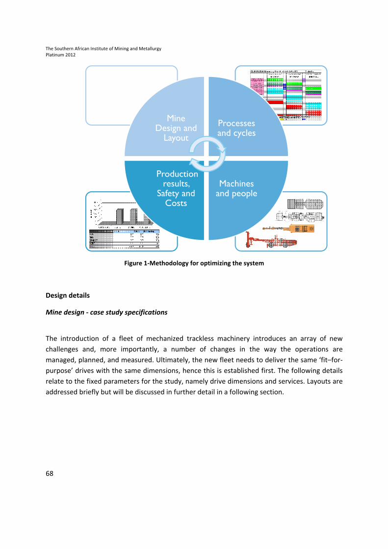
The purpose was understanding and estimating the impact of changes on the mine
performance and costs. In order to establish the most optimal state a number of scenarios were
tested, resulting in an iterative process shown in Figure 1.
The Southern African Institute of Mining and Metallurgy
Platinum 2012
68
Figure 1-Methodology for optimizing the system
Design details
Mine design - case study specifications
The introduction of a fleet of mechanized trackless machinery introduces an array of new
challenges and, more importantly, a number of changes in the way the operations are
managed, planned, and measured. Ultimately, the new fleet needs to deliver the same ‘fit–for-
purpose’ drives with the same dimensions, hence this is established first. The following details
relate to the fixed parameters for the study, namely drive dimensions and services. Layouts are
addressed briefly but will be discussed in further detail in a following section.
Mine Design and
Layout
Processes and cycles
Machines and people
Production results,
Safety and Costs
The Southern African Institute of Mining and Metallurgy
Platinum 2012
69
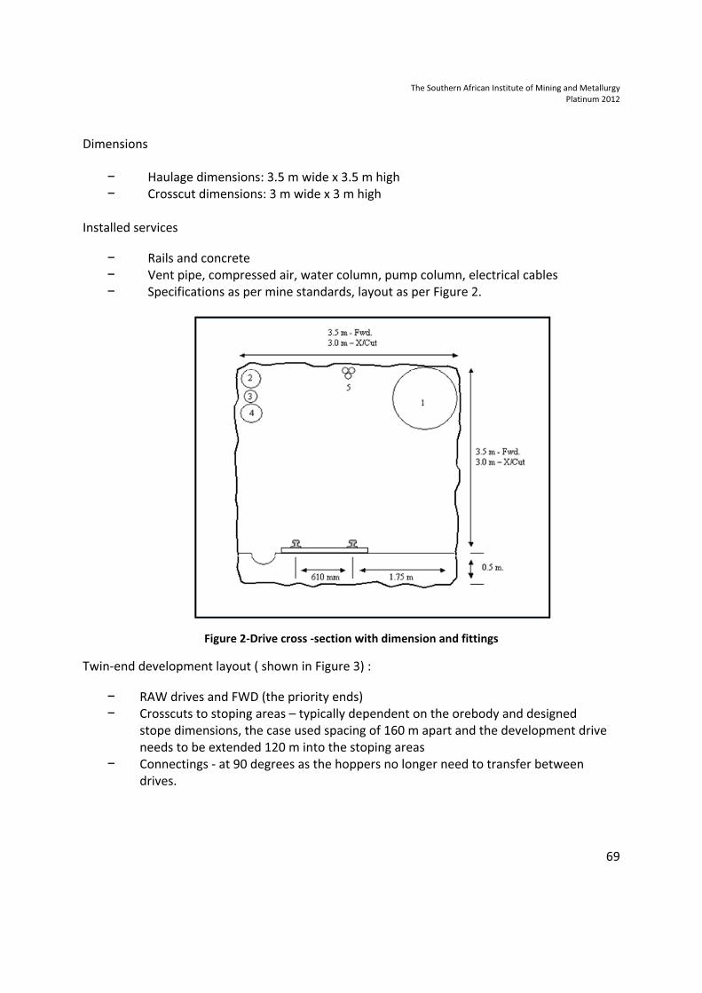
Dimensions
− Haulage dimensions: 3.5 m wide x 3.5 m high
− Crosscut dimensions: 3 m wide x 3 m high
Installed services
− Rails and concrete
− Vent pipe, compressed air, water column, pump column, electrical cables
− Specifications as per mine standards, layout as per Figure 2.
Figure 2-Drive cross -section with dimension and fittings
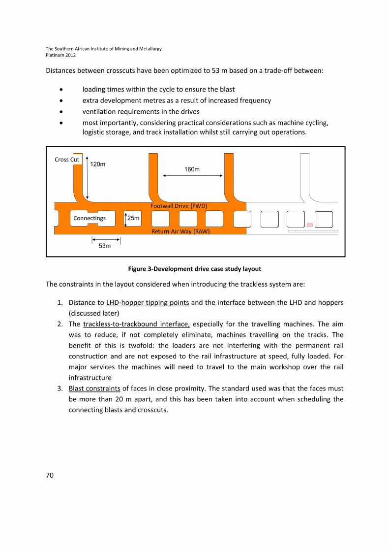
Twin-end development layout ( shown in Figure 3) :
− RAW drives and FWD (the priority ends)
− Crosscuts to stoping areas – typically dependent on the orebody and designed
stope dimensions, the case used spacing of 160 m apart and the development drive
needs to be extended 120 m into the stoping areas
− Connectings - at 90 degrees as the hoppers no longer need to transfer between
drives.
The Southern African Institute of Mining and Metallurgy
Platinum 2012
70
Distances between crosscuts have been optimized to 53 m based on a trade-off between:
• loading times within the cycle to ensure the blast
• extra development metres as a result of increased frequency
• ventilation requirements in the drives
• most importantly, considering practical considerations such as machine cycling,
logistic storage, and track installation whilst still carrying out operations.
Figure 3-Development drive case study layout
The constraints in the layout considered when introducing the trackless system are:
1. Distance to LHD-hopper tipping points and the interface between the LHD and hoppers
(discussed later)
2. The trackless-to-trackbound interface, especially for the travelling machines. The aim
was to reduce, if not completely eliminate, machines travelling on the tracks. The
benefit of this is twofold: the loaders are not interfering with the permanent rail
construction and are not exposed to the rail infrastructure at speed, fully loaded. For
major services the machines will need to travel to the main workshop over the rail
infrastructure
3. Blast constraints of faces in close proximity. The standard used was that the faces must
be more than 20 m apart, and this has been taken into account when scheduling the
connecting blasts and crosscuts.
160m
53m
Return Air Way (RAW)
Footwall Drive (FWD)
Connectings
120m
25m
Cross Cut
The Southern African Institute of Mining and Metallurgy
Platinum 2012
71
Mining activities
Each activity is considered separately initially in order to address the mining requirements
(planned dimensions and development meters). However when considering mechanized
operations no activity occurs without influence of another activity, hence a holistic approach is
considered when creating the ‘mining system’.
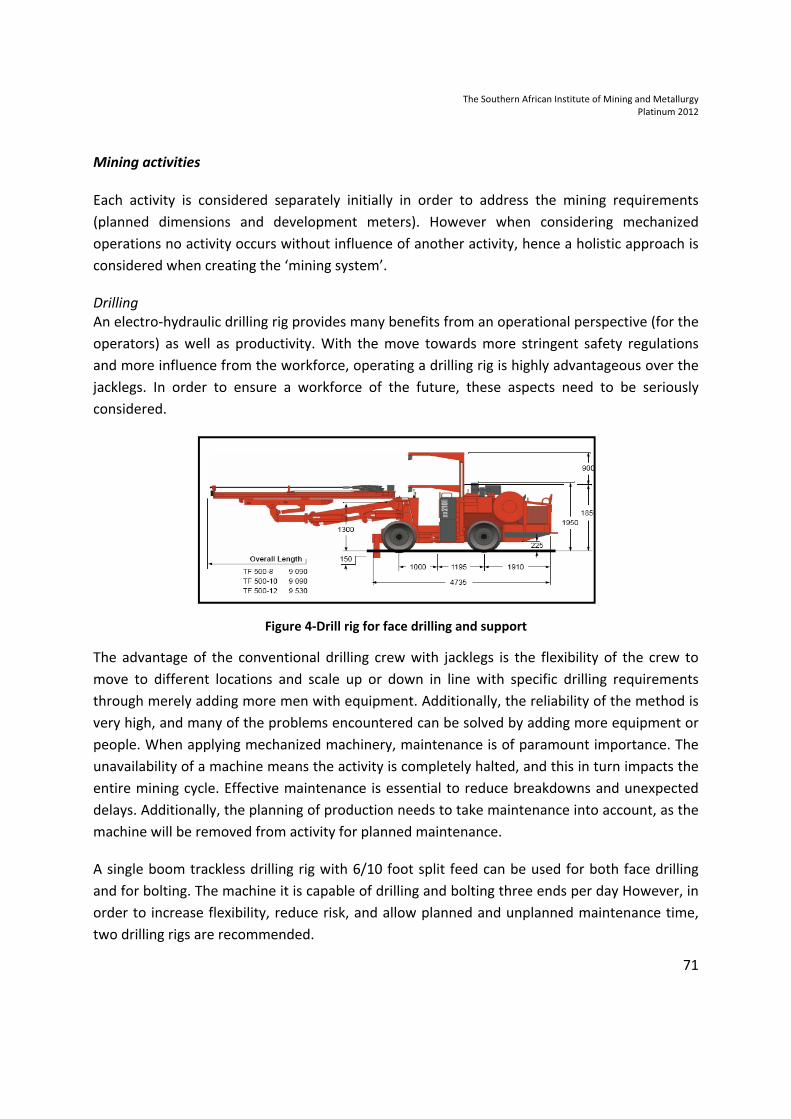
Drilling
An electro-hydraulic drilling rig provides many benefits from an operational perspective (for the
operators) as well as productivity. With the move towards more stringent safety regulations
and more influence from the workforce, operating a drilling rig is highly advantageous over the
jacklegs. In order to ensure a workforce of the future, these aspects need to be seriously
considered.
Figure 4-Drill rig for face drilling and support
The advantage of the conventional drilling crew with jacklegs is the flexibility of the crew to
move to different locations and scale up or down in line with specific drilling requirements
through merely adding more men with equipment. Additionally, the reliability of the method is
very high, and many of the problems encountered can be solved by adding more equipment or
people. When applying mechanized machinery, maintenance is of paramount importance. The
unavailability of a machine means the activity is completely halted, and this in turn impacts the
entire mining cycle. Effective maintenance is essential to reduce breakdowns and unexpected
delays. Additionally, the planning of production needs to take maintenance into account, as the
machine will be removed from activity for planned maintenance.
A single boom trackless drilling rig with 6/10 foot split feed can be used for both face drilling
and for bolting. The machine it is capable of drilling and bolting three ends per day However, in
order to increase flexibility, reduce risk, and allow planned and unplanned maintenance time,
two drilling rigs are recommended.
The Southern African Institute of Mining and Metallurgy
Platinum 2012
72
Ideally one rig should be dedicated to bolting and one to face drilling, even though essentially
the rig can perform both functions.
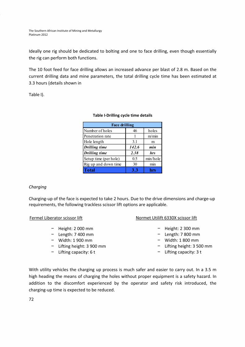
The 10 foot feed for face drilling allows an increased advance per blast of 2.8 m. Based on the
current drilling data and mine parameters, the total drilling cycle time has been estimated at
3.3 hours (details shown in
Table I).
Table I-Drilling cycle time details
Charging
Charging-up of the face is expected to take 2 hours. Due to the drive dimensions and charge-up
requirements, the following trackless scissor lift options are applicable.
With utility vehicles the charging up process is much safer and easier to carry out. In a 3.5 m
high heading the means of charging the holes without proper equipment is a safety hazard. In
addition to the discomfort experienced by the operator and safety risk introduced, the
charging-up time is expected to be reduced.
Fermel Liberator scissor lift
− Height: 2 000 mm
− Length: 7 400 mm
− Width: 1 900 mm
− Lifting height: 3 900 mm
− Lifting capacity: 6 t
Normet Utilift 6330X scissor lift
− Height: 2 300 mm
− Length: 7 800 mm
− Width: 1 800 mm
− Lifting height: 3 500 mm
− Lifting capacity: 3 t
Number of holes 46 holes
Penetration rate 1 m/min
Hole length 3.1 m
Drilling time 142.6 min
Drilling time 2.38 hrs
Setup time (per hole) 0.5 min/hole
Rig up and down time 30 min
Total 3.3 hrs
Face drilling
The Southern African Institute of Mining and Metallurgy
Platinum 2012
73
Support
The same model of machine used for face drilling will be used for support. Removing the
operator from unsupported ground, and providing him with better lift, visibility, and the ability
to drill the correct angle of holes are intangible benefits of the drilling rig. Again, the
introduction of the mechanized fleet required a change in the way the cycles need to be
planned and measured. With two rigs that can bolt or face drill this allows the shift boss
flexibility to move machines as desired. The way the mining cycles need to be arranged
(discussed in further detail below) ensures that the rig drills the bolt holes and the bolts are
installed once the face is cleaned. This eliminates the potential of support not installed to
standard, which is possible with the current set-up.
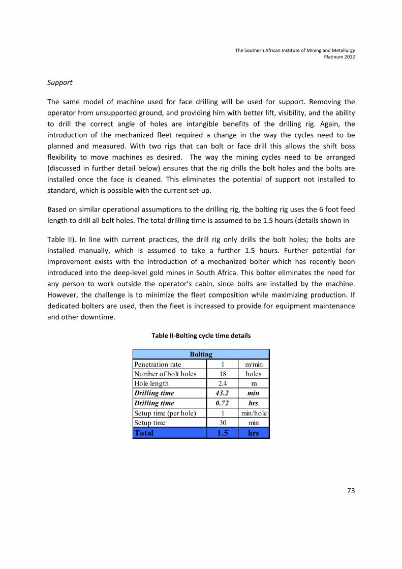
Based on similar operational assumptions to the drilling rig, the bolting rig uses the 6 foot feed
length to drill all bolt holes. The total drilling time is assumed to be 1.5 hours (details shown in
Table II). In line with current practices, the drill rig only drills the bolt holes; the bolts are
installed manually, which is assumed to take a further 1.5 hours. Further potential for
improvement exists with the introduction of a mechanized bolter which has recently been
introduced into the deep-level gold mines in South Africa. This bolter eliminates the need for
any person to work outside the operator’s cabin, since bolts are installed by the machine.
However, the challenge is to minimize the fleet composition while maximizing production. If
dedicated bolters are used, then the fleet is increased to provide for equipment maintenance
and other downtime.
Table II-Bolting cycle time details
Penetration rate 1 m/min
Number of bolt holes 18 holes
Hole length 2.4 m
Drilling time 43.2 min
Drilling time 0.72 hrs
Setup time (per hole) 1 min/hole
Setup time 30 min
Total 1.5 hrs
Bolting
The Southern African Institute of Mining and Metallurgy
Platinum 2012
74
Loading
The cleaning cycle proposed is one of the biggest changes for the conventional miner to adapt
to. The current process with boesman loaders loading onto hoppers, which in turn need to be
shunted backward and forward, is hugely inefficient and has a number of associated safety
concerns. In addition to this, the numbers of people still willing to work in such conditions are
expected to become a problem. Careful consideration was given to the current infrastructure,
mining layout, and operational requirements in order to determine a feasible and practical
loading alternative.
The constraints introduced with a trackless loader are:
a) Interface between trackless loading and trackbound hauling, additionally allowance for
stockpiling to eliminate any waiting time from the loader or hoppers
b) Extra ventilation requirements
c) Interference of the loading cycle with other operations
d) Man-machine interface ( width of the loader is larger than the boesman)
e) Distances between loading bays and transfer points need to be managed
f) Dependence on loader availability.
The following review addresses these points and provides an indication of expected
productivity based on the trade-offs conducted.
a. Loader-hopper interface
• A transition point arrangement has been devised that eliminates the loader travelling on
rails to load the hoppers, removes the need for shunting the hoppers backward and
forward, and allows for a small buffer capacity
• The transition point includes a feeder receiving rock from the loader and feeding the
hoppers at a constant rate. The feeder provides the height and constant flow rate for
the hoppers to ensure that the hoppers are filled correctly and efficiently. The feeder
has a capacity of two buckets, which allows a small buffer for the loader. An area for
stockpiling is necessary near the transition point when the train of hoppers are being
exchanged or to act as a buffer for other process delays. The stockpiling area should be
located close to the face being cleaned, in an area out of the flow of any traffic and in an
area large enough for all the rock from a blast (Figure 5)

The Southern African Institute of Mining and Metallurgy
Platinum 2012
75
• The transition point is located three connectings back from the face to allow space for
the train of hoppers to move, to allow the machines space to move freely between
drives, and to provide sufficient space for any machines to be maintained or materials to
be stored
• Matching to loader, feeder, and hoppers – the feeder acts as a buffer between the
loaders and hoppers, hence matching is not necessary. However, if the feeder is
unavailable, the loader bucket size should be in line with feeder capacity and hopper
dimensions. The hoppers in use at the moment are 2.8 m³. Based on fill factors and
heaping factors the LH306E (6 t loader) and LH307 (7 t loader) are most appropriate.
Figure 5-Trackless-trackbound transition point
b. Ventilation
• Ventilation is challenging and expensive in all operations, especially at the depths the
platinum mines are moving towards and given that the thermal gradient in platinum
mines is approximately twice that in gold mines. Diesel-powered LHDs generate
approximately three times more heat for a rated power output than similar-size electric
loaders. Consequently, the efficiencies of using electric LHDs and lack of noxious gases
allow far less ventilation for electric loaders
Rail in RAW
Transition point
trackless to
trackbound
Area available
for stockpiling
Footwall Drive (FWD)
Return Air Way (RAW)
The Southern African Institute of Mining and Metallurgy
Platinum 2012
76
• Simulation scenarios were carried out with the LH306E (6 t loader) and the LH409E (9 t
loader) based on a range of anchor points for the cable and tipping configurations
• The LH410 (10 t loader) diesel loader has 46 per cent more power output than the
LH307( 7 t loader) with their 220 kW and 150 kW engines respectively. This requires a
significant amount of extra ventilation, hence power output played a large part in loader
selection. The cycle time of the LH410 is expected to be 1.5 hours, whereas the cycle
time of the LH307 is expected to be 2.5 hours (for a maximum traveling distance of 200
m one way).
c. Interference of the loading cycle with other operations
• With the introduction of new machinery, new constraints can be expected. The nature
of the loading process sterilizes a portion of the working areas due to travel routes.
These have been considered in the light of the mining cycle with supporting machines. A
notable concern has been raised when evaluating the electric loader, that of the cable
management
• The cable lengths are 200-240 m long (for 525 V supply), which is sufficient for loading
and tipping in the layout. However, the location of the tether points posed a problem. A
situation arose where the other mining activities would be in operation in the FWD and
the loader cleaning the RAW would block access and pose a safety risk for personnel
moving around that area. It is for this reason that the electric loading options are not
practical at this point. A recommendation for further studies to be done with new
technology or new layouts should be considered.
d. Man-machine interface
• Due to the nature and flexibility of trackless machinery, several benefits are realized
(better operator comfort, safer working conditions, etc.). However, further
considerations need to be addressed. Here we discuss the man-machine interface when
considering the loader model
• The drive dimensions constrain the size of machine capable of operating safely in the
mining environment. The LH409E and LH410 are 2.5 m and 2.6 m wide respectively
(Table III). This increase in machine width requires more consideration be given to the
turning radius, especially in the connectings. Additionally, the machines in general are
wider and more mobile than the tracked boesman, and hence could pose an additional
safety hazard. To address this, in industry the general rule is to allow 40-50 cm width
allowance on each side of the machine, but this is not possible in the connecting drives
with the LH409E and LH410.

The Southern African Institute of Mining and Metallurgy
Platinum 2012
77
e. Loader tramming distances
• In the recommended shift setup, a 22 hour working day is available (discussed below),
where on average three faces need to be blasted in this time frame. Assuming one
blasting time per day, at the start of a shift three faces are waiting to be cleaned, so the
longest complete mining cycle occurs on face 3 owing to waiting for face 1 and face 2 to
be cleaned. This mining cycle is considered below based on increasing tramming
distances to evaluate the maximum distance allowable in order to achieve the
development aims (one blast per face per day) with the LH307. At the extremities the
loader will be cleaning at the end of a crosscut, so the maximum distance is expected to
be 280 m. Figure 6 shows that even with a one-way distance of 300 m the mining cycle
is still easily able to be completed in the available time
Figure 6-Mining cycle times for varying loading distances for the LH307
• Based on the average loading cycle times, the mining layout, the interference with other
mining activities, and especially considering the distance into the crosscuts, simulation
scenarios were run for varying connecting dimensions and transition point locations. It
was decided that the most optimal connecting spacing was 53 m apart and the transfer
point location should be three connectings from the furthest development face
(discussed previously). This results in an average one-way tramming distance of 150 m.
0
5
10
15
20
25
100m 150m 200m 250m 300m
To
tal
Cy
cle
tim
e (
hrs
)
Tramming Distance (one way)
Charging
Drilling
Mark-up
Drill & Install Support
Cleaning
Wait for loader
Shift Time Available
The Southern African Institute of Mining and Metallurgy
Platinum 2012
78
f. Loader availability
• In all aspects of mechanized mining operations maintenance plays a significant role in
ensuring the machines are cost-effective and more importantly available to perform the
required work. This translates to operational planning for planned maintenance where
the machine is not available for a whole shift each week and effectively managing
machine breakdowns through good communication systems, maintenance skills, and
correct tools at the very least. As can be seen from the cycle times in Figure 6, delays in
any part of the process are exacerbated due to the limited number of faces and limited
effective face time. It is recommended that two loaders are required in order to ensure
that one blast per face per day is achieved. This means that an LHD is always available
and that the longer cycle times in the crosscut do not pose any additional risks.
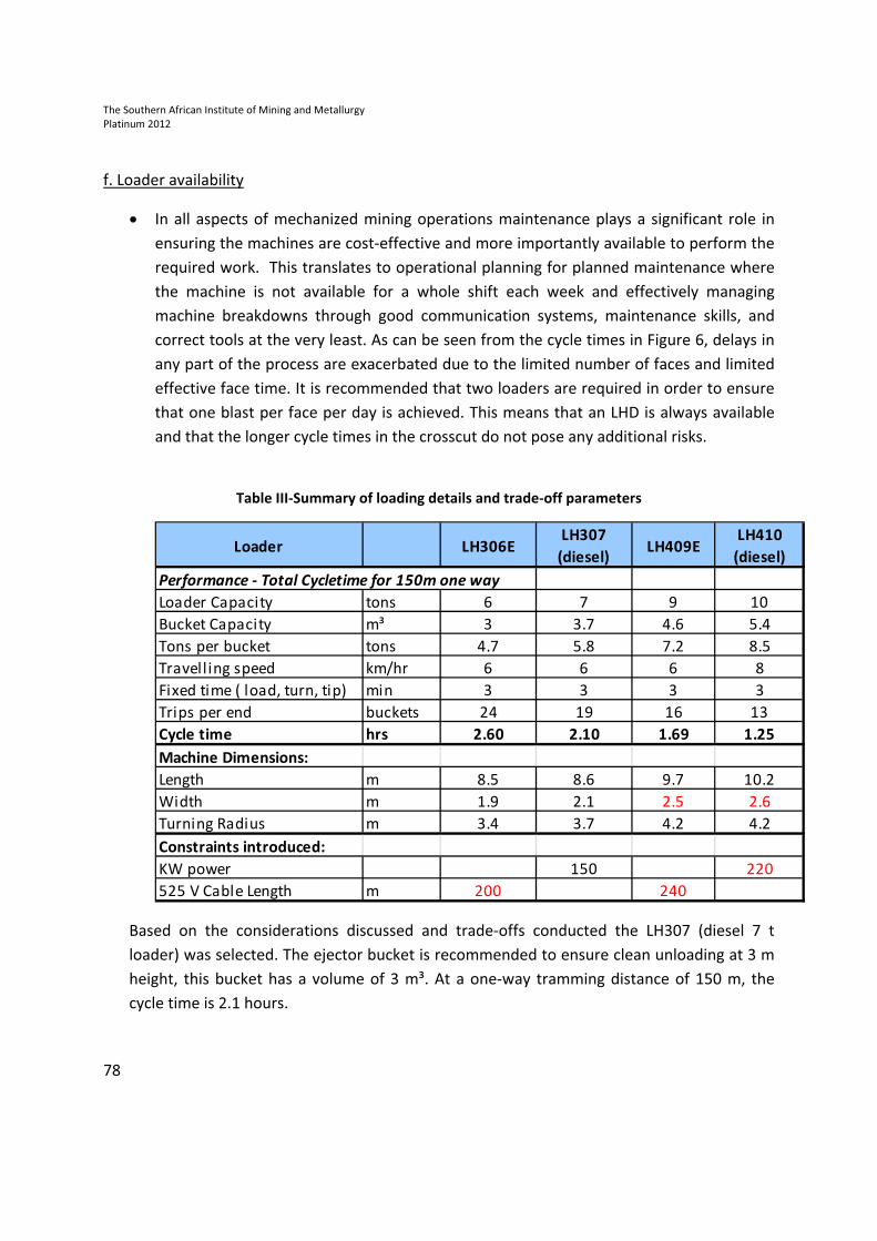
Table III-Summary of loading details and trade-off parameters
Based on the considerations discussed and trade-offs conducted the LH307 (diesel 7 t
loader) was selected. The ejector bucket is recommended to ensure clean unloading at 3 m
height, this bucket has a volume of 3 m³. At a one-way tramming distance of 150 m, the
cycle time is 2.1 hours.
Loader LH306ELH307
(diesel)LH409E
LH410
(diesel)
Performance - Total Cycletime for 150m one way
Loader Capacity tons 6 7 9 10
Bucket Capacity m³ 3 3.7 4.6 5.4
Tons per bucket tons 4.7 5.8 7.2 8.5
Travell ing speed km/hr 6 6 6 8
Fixed time ( load, turn, tip) min 3 3 3 3
Trips per end buckets 24 19 16 13
Cycle time hrs 2.60 2.10 1.69 1.25
Machine Dimensions:
Length m 8.5 8.6 9.7 10.2
Width m 1.9 2.1 2.5 2.6
Turning Radius m 3.4 3.7 4.2 4.2
Constraints introduced:
KW power 150 220
525 V Cable Length m 200 240
The Southern African Institute of Mining and Metallurgy
Platinum 2012
79
This is acceptable, since the drill rig drilling time is expected to be 3.3 hours so the drill rig
will dictate the speed of the mining cycle. With at least 50 minutes of slack time, this
reduces any risks of not cleaning out the face in the allowable time. However, extra
opportunity exists with an additional loader, allowing all the faces to be completed sooner
and if an extra face is available (crosscut and connecting) the system has the potential to
achieve four blasts.
Service installation
It is essential that the ventilation, meshing and lacing, and service piping closely follow drive
development. The assumption is that these activities do not interfere with the primary
development cycle, but need to be installed nonetheless. A scissor lift should be purchased to
aid in completing these activities safely and effectively. Acquiring a similar scissor lift to that
specified for charging allows these two machines to be interchangeable and hence reduces risk
if the machine is unavailable, increased flexibility, requires less parts-holding space and skills for
maintenance etc. These activities typically occur behind the drill rigs or when the face is waiting
to be blasted. An activity cycling diagram has been completed for each activity based on
different shift breakdowns, including the extension of services (Figure 10).
Mining sequence
In order to complete the mining cycle in the proposed manner, the following process and
practicalities have been proposed:
- During development of the section, only one rail should be installed, the rails must be
constructed in the RAW giving easy access to the crosscuts by trackless equipment
- The rails must be extended only as far as two connectings are still available. This gives
access to the machines between drives and allows space for stockpiling of the broken
rock (shown in Figure 7)
- The tip should be placed in the next closest connecting, which is the transition area for
loading the hoppers. The rail can extend beyond the tip to avoid shunting
- Trackbound waste is hauled by the hoppers in the RAW
- To control ventilation, vent walls must be installed in the connectings behind the tip.

The Southern African Institute of Mining and Metallurgy
Platinum 2012
80
Figure 7-Drive layout with initial set-up
After one month of development (estimated to be 56 m system advance) the rails can be
extended up until just before the next connecting and then the tipping point can be moved
forward. This ensures that there are sufficient routes for the trackless loaders to access the
tip without crossing the rails and the tramming distance for the loaders remains in range
(see Figure 8).
Figure 8-Drive layout with advancing parameters
160m
53m
Return Air Way (RAW)
Footwall Drive (FWD)
Connectings
120m
25m
Rail in RAW
Transition point
trackless to
trackbound
Area available
for stockpilingTipping
point
Cross Cuts
3. Tip advanced
1. Drives advance
2. Rails extended
The Southern African Institute of Mining and Metallurgy
Platinum 2012
81
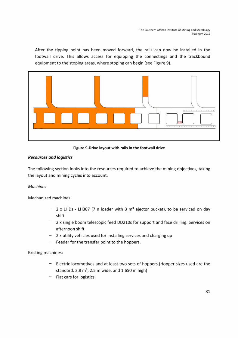
After the tipping point has been moved forward, the rails can now be installed in the
footwall drive. This allows access for equipping the connectings and the trackbound
equipment to the stoping areas, where stoping can begin (see Figure 9).
Figure 9-Drive layout with rails in the footwall drive
Resources and logistics
The following section looks into the resources required to achieve the mining objectives, taking
the layout and mining cycles into account.
Machines
Mechanized machines:
− 2 x LHDs - LH307 (7 n loader with 3 m³ ejector bucket), to be serviced on day
shift
− 2 x single boom telescopic feed DD210s for support and face drilling. Services on
afternoon shift
− 2 x utility vehicles used for installing services and charging up
− Feeder for the transfer point to the hoppers.
Existing machines:
− Electric locomotives and at least two sets of hoppers.(Hopper sizes used are the
standard: 2.8 m³, 2.5 m wide, and 1.650 m high)
− Flat cars for logistics.
The Southern African Institute of Mining and Metallurgy
Platinum 2012
82
Maintenance
The cornerstone of effective mechanized machine utilization is to ensure that machines are
serviced on schedule, inspections are conducted daily, and that there is a suitable service
facility. The service bay for the mechanized machinery will move with development. These
should be equipped approximately three connectings back from the working faces (after the
free connecting for access and the connecting for the tipping point). After this connecting
becomes available the vent doors should be installed.
Re-fuelling
Refuelling of the loaders is to be done from a 1000/2000 litre drum on a flat top on rails. This
reduces the lost time due to tramming long distances to refuel points.
Services and rail are extended with development and advance of the RAW and FWDs (to be
discussed later)
Labour
Labour is a crucial aspect in the mining process and comes with higher and higher risks. The
labour component will be discussed next. An important factor in activity cycling is the amount
of available working time at the face. The activity cycling has been done on three different shift
structures.
The options available are:
Two-shift set-up:
• 2 x 8.5 hour shifts and 1 half shift for loading. This allows 22 actual working hours out of
28 shift hours worked in a 24 hour day. The shift times are shown in Table IV below for
illustrative purposes. The objective in overlapping shift times is to reduce idle time at
the face. This is essential in such deep and extensive mines where travelling time to the
working end can take up to one hour.

The Southern African Institute of Mining and Metallurgy
Platinum 2012
83
TableIV-Working times of the two-shift set-up
Three-shift set-up:
• 2 x 9 hour shifts and 1 x 10 hour shift resulting in 28 hours shift time and 22 hours actual
work time.
Multiblast set-up:
• 3 x 10 hour shifts, these are overlapped to allow for changeovers and mining delays
associated with SOS and EOS procedures. This results in 30 hours’ shift time and 24
hours actual work time. The major differentiator in multiblast operation is the
assumption that blasts can be carried out at any time of the day (ventilation and
regulation permitting).
Based on the shift options and mining cycles required, as well as current labour structures, the
number of labour required for each shift setup has been estimated. An example is shown in
Table V. The total number of people has been estimated to be:
− Two-shift set-up: 43 people
− Three-shift set-up: 53 people (increase due to full afternoon shift)
− Multiblasting: 57 people (4 extra to charge up on all shifts).
Shift Shift Times Hours
Night Shift 10-00pm to 06-30am 8.5
Day Shift 06-30am to 03-00pm 8.5
Afternoon Shift 05-00pm to 10-00pm 5
22
Shift Shift Times Hours
Night Shift 09-00pm to 07-30am 10.5
Day Shift 05-30am to 04-00pm 10.5
Afternoon Shift 04-00pm to 11-00pm 7
28
Work Hours
Actual Shift Hours
Work face time
Payment time

The Southern African Institute of Mining and Metallurgy
Platinum 2012
84
Table V: Labour structure for a two-shift set -up
Labour skill requirement change with the introduction of the mechanized fleet. These higher
skills needs to be planned for upfront through training (for both mining personnel and
maintenance personnel), outsourced, or recruited from outside. It is recommended that
appropriate training facilities/programmes are considered to ensure the sustainability of the
operations. Special attention should be paid to the supervisors. New skills are required for
achieving successful mechanized operations, it is not just a change in the machinery.
Mining cycles
Activity cycling simulation scenarios look at the activity cycle times, number of faces, and shift
set-up. This allows one to determine the amount of blasts that can be achieved on each face
and hence determine the face utilization or potential for improved development performance.
Figure 10 shows the activity cycling based on the two-shift setup and highlights the relationship
between each activity and the utilization of the face. This has been done for all shift set-up
alternatives and run over 6 months.
1 Shift Supervisor 1 Shift Supervisor 1 Shift Supervisor
1 Miner 1 Miner 1 Miner
1 Face Drill Operator 1 Loader Operator 1 Bolter Drill Operator
1 Helper 2 Locomotive Driver 1 Helper
1 Loader Operator 2 Helper 2 Rockbolt Installation
1 Locomotive Driver 2 Meshing / Lacing 1 Face Drill Operator
1 Helper 1 Ventilation 1 Helper
2 Meshing / Lacing 1 Pipes 1 Loader Operator
1 Ventilation 2 Locomotive Driver
1 Pipes 2 Helper
4 Charge up 2 Meshing / Lacing
1 Ventilation
1 Pipes
15 11 17
43Total Crew Numbers
SHIFT STRUCTURE - 2 SHIFTS
Night ShiftDay Shift Afternoon Shift
*From below Mine Overseer

The Southern African Institute of Mining and Metallurgy
Platinum 2012
85
Figure 10-Activity cycling for two-shift set-up
The focus of the activity cycling is to understand the constraints in the system and to determine
the development metres achievable. In the additional columns the services have also been
accounted for, these include meshing and lacing, extending ventilation, and extending other
mine services ( compressed air, power, and water). These are not considered part of the critical
path but can occur behind the primary activities.
DEVELOPMENT
END FWD
DEVELOPMENT
END RAW
DEVELOPMENT
END X-Cut
blast blast blast
blast blast blast
DA
Y O
NE
12 to 1-00pm
Lo
ad
ing
Nig
ht S
hift
Da
y S
hift
Da
y S
hift
Nig
ht S
hift
Lo
ad
ing
10-00am to 11-00am
10-00pm to 11-00pm
3-00am to 4-00am
4-00am to 5-00am
5-00am to 6-00am
4-00pm to 5-00pm
5-00pm to 6-00pm
6-00pm to 7-00pm
7-00pm to 8-00pm
9-00pm to 10-00pm
8-00am to 9-00am
11-00pm to 12-00
1-00pm to 2-00pm
11-00pm to 12-00
6-00am to 7-00am
7-00am to 8-00am
8-00pm to 9-00pm
2-00pm to 3-00pm
3-00pm to 4-00pm
2-00am to 3-00am
12 to 1-00pm
1-00pm to 2-00pm
2-00pm to 3-00pm
8-00am to 9-00am
9-00am to 10-00m
10-00am to 11-00am
12 to 1-00am
9-00pm to 10-00pm
10-00pm to 11-00pm
3-00pm to 4-00pm
4-00pm to 5-00pm
5-00pm to 6-00pm
6-00pm to 7-00pm
7-00pm to 8-00pm
11-00am to 12-00
1-00am to 2-00am
DA
Y T
WO
12 to 1-00am
1-00am to 2-00am
2-00am to 3-00am
3-00am to 4-00am
4-00am to 5-00am
9-00am to 10-00m
7-00am to 8-00am
8-00pm to 9-00pm
5-00am to 6-00am
6-00am to 7-00am
11-00am to 12-00
BLASTING and RE-ENTRY
BLASTING and RE-ENTRY
3hrs
and Pump
Columns2hrs
3hrs
1.5hrs
Load face
Meshing / Lacing
Drill Support
Install Support
Mark up face
Drill face
Extend Ventilation
3hrs
1.5hrs
2hrs
.5hr
1.5hrs
Charge face
The Southern African Institute of Mining and Metallurgy
Platinum 2012
86
Typically these services are installed while drilling, bolting, or charging the end. This activity
cycles diagram (Figure 10) excludes the connecting development due to the priorities set for
the simulation month. Cycle diagrams are applied in line with faces available.
In the activity cycling a number of assumptions have been made, these include:
1. 30 minutes idle time at the start of shift (once already at the face)
2. 30 minutes idle time between activities
3. 2 hour blast and re-entry time
4. One machine is dedicated to drilling, one machine is dedicated to bolting, and one
loader is used for loading.
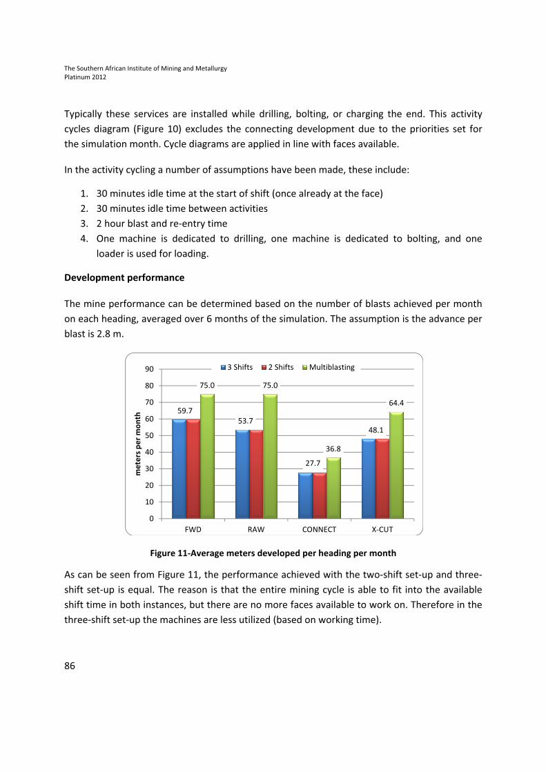
Development performance
The mine performance can be determined based on the number of blasts achieved per month
on each heading, averaged over 6 months of the simulation. The assumption is the advance per
blast is 2.8 m.
Figure 11-Average meters developed per heading per month
As can be seen from Figure 11, the performance achieved with the two-shift set-up and three-
shift set-up is equal. The reason is that the entire mining cycle is able to fit into the available
shift time in both instances, but there are no more faces available to work on. Therefore in the
three-shift set-up the machines are less utilized (based on working time).
59.7
53.7
27.7
48.1
75.0 75.0
36.8
64.4
0
10
20
30
40
50
60
70
80
90
FWD RAW CONNECT X-CUT
me
ters
pe
r m
on
th
3 Shifts 2 Shifts Multiblasting

The Southern African Institute of Mining and Metallurgy
Platinum 2012
87
System advance achieved for two- and three-shift set-up is equivalent to 56.7 m system
advance per month. In multiblast conditions, this system advance is expected to reach 75 m per
month. These performance numbers can be compared to that seen in industry in trackbound
operations: numbers in the range of 30-40 m/month are typical (Figure 12).
Figure 12-Development performance per month
As mentioned throughout, not only are there performance benefits but with the increased
metres there are labour efficiencies to be gained. Based on the data in Table VII it is evident that
labour effectiveness increases by 25 % - 54 %.
Table VII-Summary of development performance and labour productivity
*Conventional 3 shifts 2 shifts Multiblasting
Average metres per month 189 189 251
Number of people per crew 53 43 57
Metres per man 2.9 3.6 4.4 4.4
0
50
100
150
200
250
300
Conventional 3 Shifts setup 2 Shifts setup Multiblasting
189 189 251
To
tal
me
ters
pe
r m
on
th
The Southern African Institute of Mining and Metallurgy
Platinum 2012
88
Conclusions
With current technology and operating practices, the application of trackless mechanized
machines in trackbound infrastructure is possible and practical, offering not only production
benefits but also reducing safety hazards and employing labour more effectively and
sustainably.
A mind-set expresses concerns that mechanization is perceived to be costly, inflexible, and not
reliable in delivering performance. However, with the proposed system these concerns have
been sufficiently addressed through the fleet selection and shift set-up where the machines are
semi-redundant (for the loading) or dedicated to activities (bolting and face drilling) to allow
for effective maintenance and ensuring all processes are completed as scheduled. The
proposed fleet would consist of 2 x LHDs, 2 x drilling rigs, and 2 x utility vehicles working in
conjunction with the current trains and hoppers.
In the given environment, with two development ends, cross-cuts, and connecting drives, on
average three faces are available for the fleet, and the planned system advance is significantly
higher than that currently being achieved. According to the simulations, 56 m per month can be
expected, and up to 75 m/month in multiblast conditions.
Labour productivity increases by 25-54 per cent, depending on the shift set-up. This has far-
reaching implications; not only can the mine generate more development metres with the
same workforce, but the workforce is now operating in safer working environment; has a better
working environment;, and applies higher skills to the task at hand. The job is less taxing and
allows the workforce to work longer before becoming fatigued, and remain in a better state
(physically and mentally), which in turn has further knock-on benefits.
The major challenge is to allow the machines to perform to their potential, far surpassing
production numbers currently seen in conventional development with the same workforce,
which necessitates a shift in the mind-set from shift supervisors and above.

The Southern African Institute of Mining and Metallurgy
Platinum 2012
89
The Author
Danielle Nardini, trans4minetm
Project Manager – Systems, Sandvik Mining
After graduating from Wits in 2006 I started work as a junior engineer at Sandvik. As an
Industrial engineer in the mining industry my role has been to optimise mining productivity
through a structured and quantitative. This typically entails the development and application of
specific tools and approaches on mining sites globally. I started out applying the tools on
strategic customer sites, both locally and globally, as I gained more experience I moved into
developing new tools and took on a bigger role within the team and gained more mining
exposure. Currently as a project manager I am also involved in customer liaison and feedback,
and ensuring the team delivers what the customer expects.

The Southern African Institute of Mining and Metallurgy
Platinum 2012
90


