
University of KentuckyUKnowledge
University of Kentucky Master's Theses Graduate School
2007
A CONTROLLER AREA NETWORK LAYERFOR RECONFIGURABLE EMBEDDEDSYSTEMSNithyananda Siva JeganathanUniversity of Kentucky, [email protected]
Click here to let us know how access to this document benefits you.
This Thesis is brought to you for free and open access by the Graduate School at UKnowledge. It has been accepted for inclusion in University ofKentucky Master's Theses by an authorized administrator of UKnowledge. For more information, please contact [email protected].
Recommended CitationJeganathan, Nithyananda Siva, "A CONTROLLER AREA NETWORK LAYER FOR RECONFIGURABLE EMBEDDEDSYSTEMS" (2007). University of Kentucky Master's Theses. 484.https://uknowledge.uky.edu/gradschool_theses/484

Abstract of Thesis
A CONTROLLER AREA NETWORK LAYER FOR RECONFIGURABLE
EMBEDDED SYSTEMS
Dependable and Fault-tolerant computing is actively being pursued as a research area since the 1980s in various fields involving development of safety-critical applications. The ability of the system to provide reliable functional service as per its design is a key paradigm in dependable computing. For providing reliable service in fault-tolerant systems, dynamic reconfiguration has to be supported to enable recovery from errors (induced by faults) or graceful degradation in case of service failures. Reconfigurable Distributed applications provided a platform to develop fault-tolerant systems and these reconfigurable architectures requires an embedded network that is inherently fault-tolerant and capable of handling movement of tasks between nodes/processors within the system during dynamic reconfiguration. The embedded network should provide mechanisms for deterministic message transfer under faulty environments and support fault detection/isolation mechanisms within the network framework. This thesis describes the design, implementation and validation of an embedded networking layer using Controller Area Network (CAN) to support reconfigurable embedded systems. KEYWORDS: Dependable Computing, Fault Tolerance, Embedded Networks, Distributed system, Controller Area Network (CAN).
Nithyananda Siva Jeganathan
10/17/2007

A CONTROLLER AREA NETWORK LAYER FOR RECONFIGURABLE EMBEDDED SYSTEMS
By
NITHYANANDA SIVA JEGANATHAN
DR. JAMES E. LUMPP Jr.
Director of Thesis
DR.YU MING ZHANG
Director of Graduate Studies
10/17/2007
RULES FOR THE USE OF THESIS
Unpublished theses submitted for the Master’s degree and deposited in the University of
Kentucky Library are as a rule open for inspection, but are to be used only with due
regard to the rights of the authors. Bibliographical references may be noted, but
quotations or summaries of parts may be published only with the usual scholarly
acknowledgements.
Extensive copying or publication of the dissertation in whole or in part also requires the
consent of the Dean of the Graduate School of the University of Kentucky.
A library that borrows this project for use by its patrons is expected to secure the
signature of each user.
Name Date ________________________________________________________________________ ________________________________________________________________________ ________________________________________________________________________ ________________________________________________________________________ ________________________________________________________________________ ________________________________________________________________________ ________________________________________________________________________ ________________________________________________________________________

THESIS
NITHYANANDA SIVA JEGANATHAN
The Graduate School
University of Kentucky
2007

A CONTROLLER AREA NETWORK LAYER FOR RECONFIGURABLE EMBEDDED
SYSTEMS
THESIS
A thesis submitted in partial fulfillment of the requirements for the degree of Master of
Science in the College of Engineering
at the University of Kentucky
By
Nithyananda Siva Jeganathan
Lexington, KY
Director: Dr. James E. Lumpp Jr. , Professor of Electrical Engineering
Lexington, KY
2007

Dedicated to my family, friends and
to Almighty who shows me the way…

Acknowledgements
I would like to thank my advisor Dr. James E. Lumpp, Jr. for his invaluable guidance and
support, without which this work would not have been possible. I am grateful for the
motivation and the inspirations he had provided. I would also like to thank my Thesis
Committee members Dr. Henry G. Dietz and Dr. William R. Dieter not only for serving on
the committee, but also for providing me with great learning opportunities.
This work is dedicated to my loving family and to Seema for their understanding, support
and for being the guiding light of my life. Their love and sacrifices made everything possible
and words cannot express my gratitude.
I would like to thank Nate Rhodes and Niveditha for their painstaking efforts in proof-
reading of the thesis work and their valuable suggestions. Last, but not the least I thank my
friends who had motivated me and stood by me in everything.
iii

Table of Contents Acknowledgements .................................................................................................................. iii List of Figures .......................................................................................................................... vi List of Tables .......................................................................................................................... vii Chapter 1: Introduction ............................................................................................................. 8
1.1 Background ............................................................................................................... 8 1.2 Embedded Networks Overview ................................................................................ 9 1.3 Data Communication Protocols .............................................................................. 11
1.3.1 Message Oriented Protocols ........................................................................... 12 1.4 Medium Access Control (MAC) ............................................................................. 13 1.5 Ardea Run-time Environment ................................................................................. 14
1.5.1 IDEAnix Framework ...................................................................................... 16 1.6 Embedded Network Selection ................................................................................. 18
1.6.1 CAN Advantages ............................................................................................ 21 1.7 Problem Statement .................................................................................................. 21
Chapter 2: CAN Protocol and Applications............................................................................ 24
2.1 CAN Applications ....................................................................................................... 24 2.1.1 Vehicle Application: Light Electrical Vehicles (LEVs) ...................................... 25 2.1.2 Marine Applications: Autonomous/ Manned vehicles ........................................ 25 2.1.3 Space Applications: CANAerospace ................................................................... 26
2.2 CAN Protocol Specification ....................................................................................... 27 2.2.1 CAN Physical Layer ............................................................................................ 28 2.2.2 CAN Bit timing for the Physical Layer ............................................................... 28 2.2.3 CAN Error detection ............................................................................................ 36
Chapter 3: CAN Hardware ...................................................................................................... 39
3.1 CAN Hardware Properties: ........................................................................................... 39 3.1.1 CAN Controller Chips ......................................................................................... 39 3.1.2 CAN Transceiver chips ........................................................................................ 39 3.1.3 CAN Repeaters .................................................................................................... 40 3.1.4 CAN Bridges ........................................................................................................ 40 3.1.5 CAN Gateways .................................................................................................... 40
3. 2 CAN Microcontrollers Overview .............................................................................. 40 3.2.1 Silicon Laboratories ............................................................................................. 41 3.2.2 Infineon Technologies ......................................................................................... 41 3.2.3 Texas Instruments ................................................................................................ 43 3.2.4 Design Choice of Microcontroller ....................................................................... 43
3.3 C_CAN Controller Overview ..................................................................................... 44 3.3.1 C_CAN Engine .................................................................................................... 44 3.3.2 C_CAN Registers................................................................................................. 45
iv

Chapter 4: ENDURA Design & Implementation Details ....................................................... 48 4.1 Special Function Register Access in C8051F04x Processors ..................................... 48 4.2 ENDURA Design.......................................................................................................... 49
4.2.1 Initialization Module ............................................................................................ 52 4.2.2 Register Module ................................................................................................... 56 4.2.3 Unregister Module ............................................................................................... 61 4.2.4 Get Packet Module ............................................................................................... 64 4.2.5 Send Packet Module ............................................................................................ 65 4.2.6 Translation Module (CAN2.0A CAN2.0B CAN2.0A) ................................ 70 4.2.7 CAN Interrupt Service Routine ........................................................................... 73
Chapter 5: CAN Performance & Reliability Tests ................................................................. 79
5.1 Background ................................................................................................................. 79 5.2 Test bench Set-up ........................................................................................................ 79
5.2.1 Steps to set up the test-bench ............................................................................... 81 5.3 CAN 2.0A/ B conformance testing ............................................................................. 82
5.3.1 Register identifier test .......................................................................................... 82 5.3.2 Unregister a Message Identifier Test ................................................................... 83 5.3.3 Send Packet Test .................................................................................................. 85 5.3.4 Receive packet module test .................................................................................. 86
5.4 Performance Testing of ENDURA ............................................................................. 86 5.4.1 Bandwidth Tests and Analysis ............................................................................. 87 5.4.2 Latency Tests ....................................................................................................... 92 5.4.3 Reliability testing ................................................................................................. 97 5.4.4 Sporadic Packet Tests ......................................................................................... 98
5.5 Performance Analysis Summary................................................................................. 99 Chapter 6: Conclusion........................................................................................................... 101 Appendix A: CAN Protocol Specification ............................................................................ 103
Appendix B: C_CAN Processor ........................................................................................... 109
References ............................................................................................................................. 114 Vita ........................................................................................................................................ 118
v

List of Figures Figure 1: Distributed system view on a UAV [2] ..................................................................... 9 Figure 2: OSI Layer Reference Architecture .......................................................................... 10 Figure 3: Node oriented communication ................................................................................ 11 Figure 4: Message oriented communication ........................................................................... 12 Figure 5: Ardea Dependency Graph model [26] ..................................................................... 16 Figure 6: IDEAnix Block diagram and Task level communication with MeRL [4] .............. 17 Figure 7: MeRL block diagram [4] ......................................................................................... 18 Figure 8: State Diagram for CAN Engine ............................................................................... 31 Figure 9: CAN Data Frame Format ........................................................................................ 32 Figure 10: CAN Remote Request Frame ................................................................................ 34 Figure 11: Error Frame Format ............................................................................................... 35 Figure 12: Block Diagram of CAN Application ..................................................................... 51 Figure 13: CAN Module block diagram ................................................................................. 52 Figure 14: Flow chart for initialization module ...................................................................... 54 Figure 15: Flow chart for Register module ............................................................................. 57 Figure 16: Flow chart for Unregister module ......................................................................... 62 Figure 17: Flow chart for Send Message Module ................................................................... 66 Figure 18: Translation Module block Diagram ...................................................................... 71 Figure 19: Flowchart for CAN ISR functionality ................................................................... 74 Figure 20: Block diagram for ENDURA test set up ............................................................... 80 Figure 21: Test Bench Setup for ENDURA layer testing ....................................................... 80 Figure 22: Test bench set up (a closer look) ........................................................................... 81 Figure 23: Bandwidth Graph for Packet rate Vs Packets dropped ......................................... 90 Figure 24: Block diagram representing different times measured in Latency tests ................ 93 Figure 25: Timing diagram for receiving a packet ................................................................. 94 Figure 26: Timing diagram for Sending packet ...................................................................... 95 Figure 27: Test Register Details ........................................................................................... 109
vi

vii
List of Tables Table 1: Design matrix for the embedded networks .............................................................. 20 Table 2: CAN frame format for a basic CAN 2.0A frame ...................................................... 33 Table 3: Bandwidth Analysis report for 100ms tick delay ..................................................... 88 Table 4: Bandwidth Analysis report for 10ms tick delay ....................................................... 89 Table 5: Bandwidth Analysis with number of packets sent over time ................................... 90 Table 6: Reliability test data after continuous run for 40 hours ............................................. 97 Table 7: Sporadic Test data for CAN ..................................................................................... 98 Table 8: Test Register Bits .................................................................................................... 109 Table 9: List of Protocol Registers in C_CAN processor ..................................................... 111 Table 10: List of Interface Registers in C_CAN processor .................................................. 112 Table 11: List of Message handler Registers in C_CAN processor ..................................... 113

Chapter 1: Introduction This chapter provides a background and introduction to the problem of providing a
networking layer to support reconfigurable systems, embedded network architectures,
data communication protocols, media access control logics are discussed. The motivation
for the thesis is discussed along with the different embedded networks options and
motivation for the choice of Controller Area Network (CAN) as the desired embedded
network. Finally the goals for the system to be developed are described in detail.
1.1 Background Dependable and Fault-tolerant computing is being actively pursued as a research area for
deployment in safety-critical applications where guaranteed functional operations of
system is paramount. The system should provide reliable services based on its functional
design and this key requirement is the motivation for implementing fault-tolerant
techniques in system. A Fault-tolerant system should be capable of detecting faults/
errors in the system and also provide minimal services in case of recoverable errors or
degrade gracefully in case of failures. Any distributed system depends on a network
mechanism for establishing communication between the different nodes and for a
reconfigurable distributed architecture, the embedded network should provide
mechanisms for deterministic message transfer under faulty environments and support
fault detection/isolation mechanisms within the network framework.
This thesis research work presents an implementation of an Embedded Network Driver
for Use on Reconfigurable Architectures (ENDURA) that supports fault-tolerant
mechanisms and can be integrated into any reconfigurable architecture as a network
layer. Controller Area Network is a differential signaling serial bus that was developed by
Robert Bosch GmbH for deployment as a system bus in Automobiles. For analyzing the
efficiency of the ENDURA implementation using CAN, a typical safety-critical
distributed system using an Unmanned Aerial Vehicle (UAV) will be considered as an
example where required. Figure 1 shows the system view for a distributed UAV system.
The Tiny Interface Module (TIM) processor boards [2] are embedded on servos and
8

mounted on the wings and the ailerons. The processor boards are connected through a
CAN bus that provides the communication mechanism for the UAV system.
Figure 1: Distributed system view on a UAV [2]
The other CAN applications that are used in Small vehicles (Light Electric Vehicles),
Marine applications (SeaCAN, NAUTILE) and Space applications (SOFIA, SMART-1)
are discussed in detail in Chapter 2.
1.2 Embedded Networks Overview An overview of the embedded networks is provided in this section. The nodes in a
network can communicate with each other or nodes outside their network through a
variety of software architecture models and physical layers (PHY). Two of the most
popular software architectures in use are the Transfer Control Protocol (TCP)/Internet
Protocol (IP) suite and the International Standards Organization (ISO)/Open Systems
Interconnection (OSI) Reference model (also known as the seven layer ISO/OSI
Reference model) [28].
The TCP/IP model was developed by the Department of Defense (DoD) to establish
connections between nodes of different types within different networks [26] . The TCP/IP
model was designed to provide guaranteed delivery of information between systems and
9

includes a sliding window protocol controlled by congestion control mechanisms [27].
The TCP/IP model led to the interconnection of networks and to the origin of the Internet.
The main reference for most of the present embedded networks protocol specifications is
the ISO/OSI Reference model [28]. It is devised by the International Standards
Organization to support open networks communications and also to encapsulate the
existing interconnection standards within the ISO reference model. The model does not
define the exact implementation methodologies but rather defines the mutual recognition
and support of the applicable standards. For more detailed description on the ISO/ OSI
model and implementation requirements refer to [28].
Figure 2 shows the communication mechanism for the OSI Model and classifies 7
different layers based on their functionality. The ISO/ OSI model form the basis for many
of the industrial and embedded networks that are in use today [28].
Figure 2: OSI Layer Reference Architecture
10

1.3 Data Communication Protocols The data communication protocols basics that are currently being used in many
applications are discussed in the following sections. The data communication protocols
can be broadly classified into two categories:
1. Node Oriented Protocols
2. Message Oriented Protocols
Node Oriented Protocols
In node oriented protocols the information is exchanged between nodes by their node
address. Hence the sender transmits the data with the destination node’s unique address,
that is either predefined for the network or can be obtained through a query message and
also optionally the sender’s source address. Typically reserved address(es) is/are
designated for broadcasting information to all or a group of nodes in the network. In the
node oriented scheme, besides specifying the receiver’s nodes address, the content of the
transmitted message needs to be specified as well. In general, all the information sent
across the network follow the same packet formats with payload (or data field) variations.
The information sent across network could be a fixed sized payload or variable payloads.
Figure 3: Node oriented communication
11

Figure 3 shows a generic network based on node oriented protocols. The packet format is
to send the Destination address (Node 3) of the node being addressed to and optionally
the Sender’s address (Node 1). An example of a Node oriented communication is the
Ethernet network technology [29].
1.3.1 Message Oriented Protocols In Message Oriented Protocols the information is exchanged between nodes through a
Frame or Message Identifiers. The Node transmitting the data sends the information on
the bus with a unique Message Identifier. The nodes on the network make the decision on
accepting or dropping the packets that arrive through the bus. The Frame sent could be
received by one/some/all or none of the nodes. Since the transmitting node does not get
any acknowledgement of the data sent, confirmed message exchange is not suitably
realized [23]. This can be overcome via error-signaling techniques that enable the
receiver inform the sender of problems on the network. There are no reserved message
identifiers or broadcast message identifiers unlike the Node oriented protocols. The
arbitration purely depends on the message identifiers transmitted and higher preference is
normally for lower numbered message identifiers.
Figure 4: Message oriented communication
12

Figure 4 shows the communication between nodes in a message oriented methodology.
The packet that is sent on the network contains only the Message Identifier and not the
destination node’s address as in Node oriented mechanism. For example: in Figure 4
Node 2 rejects the packet and Node 3 accepts the packet. Example of a message oriented
network is Controller Area Network [6].
1.4 Medium Access Control (MAC) Medium Access Control (MAC) is the mechanism of establishing asynchronous
communication between nodes and this section briefs in detail on the strategies used on
the embedded networks in general. MAC determines which transmitter gets control over
the media for transmission. The MAC logic arbitrates between 2 or more nodes from
transmitting at the same time and prevents collision of information from different nodes.
MAC decisively controls the Real-time behavior and packet latency and choice of MAC
is essential in choosing the data communication protocol.
MAC can be generally classified into two categories as methods with deterministic access
and methods with random bus access. Deterministic bus access methods are in turn
classified into two methods as allowing centrally controlled arbitration and distributed
controlled arbitration. The non-deterministic or random bus access is classified into two
methods as methods allowing collisions and no collisions methodology.
In deterministic bus access method, the arbitration is clearly broken prior to a bus access
thus guaranteeing that only one node will get the bus for transmission. The maximum
system response time can be determined for the bus with accuracy. In centrally controlled
deterministic access, one or more nodes act as the master and determine which node gets
the bus. But if the master/s fails, then network communication is impossible. In
distributed controlled deterministic access, the arbitration is broken by individual nodes
based on a protocol and not controlled by a master node. Hence even if one or more
nodes fail in the network, communication is still possible between the remaining nodes.
Distributed controlled arbitration is more robust in fault-tolerant applications, but its
implementation is more complex than the centrally controlled arbitration.
13

In random bus access, any node on the network could send information once the bus is
idle. Since many different nodes can sense that the bus is idle at the same time, it is
referred to as Carrier Sense Multiple Access (CSMA). The random bus access can be
implemented with Collisions or without collisions. The random bus access without
collisions differs from collision-free bus access (as in deterministic bus access
implementation). The CSMA method in which collisions can occur but also can be
detected is called Carrier Sense Multiple Access/ Collision Detection (CSMA/CD). The
CSMA method in which collisions can occur but are identified later as error in
communication is implemented in the Local Operating Network protocol (LON) [23].
CSMA in which there are no collisions are called Carrier Sense Multiple Access/
Collision Avoidance (CSMA/CA).
1.5 Ardea Run-time Environment This section provides an overview on the Automatically Reconfigurable Distributed
Embedded Architectures (ARDEA) framework and the basic concepts of dependability
and fault-tolerance. Any safety-critical system that is being developed is a multitude of
hardware and software and the ability of the system to provide reliable functional service
as per its design is a principal paradigm in dependable computing.
In order to achieve high reliability on the data obtained, the system must be able to
withstand the errors that are generated in the system (either deliberate or due to design
flaws) or in case of failures, degrade gracefully or provide reduced services [25]. Hence a
fundamental requirement for any dependable system is to be fault-tolerant and to achieve
fault tolerance within the system redundant processing structures will have to be
incorporated in the system design phase [25].
ARDEA framework considers reconfiguration of the system as a mechanism of providing
fault-tolerance. Ardea framework supports traditional fault-tolerant techniques using
redundant modules and also graceful degradation [26]. The graceful degradation implies
that the system will reconfigure dynamically to produce reduced services of operation
14

depending on the type of fault suffered by the system and as the reconfiguration schemes
are supported in addition to the traditional fault tolerant schemes, make the Ardea
framework highly efficient in handling faults on the system. The dynamic reconfiguration
allows fault-tolerant applications to identify alternate modes of operation and not suffer
system failure during a catastrophic error, but rather have reduced services for the system
through reconfiguration.
The Ardea framework allows for reconfiguration of the architecture by capturing the
system architecture as Dependency Graphs (DG) and the DG’s indicate flow of data
between the modules within the Ardea framework. Redundant modules are also
incorporated into the DGs and the decision of correct data can be made by the process of
voting between the redundant modules. The voting process is represented using Logic-
gates on the DG and hence a DG can be used to represent redundant modules, logic gates,
input and output sources and the quality of the input or output sources. The flow of
information on a DG starts from the input sources end and terminates at the output
devices section. Figure 5 shows a model Ardea DG that shows functional flow of
information from the input modules to the output modules.
15

Figure 5: Ardea Dependency Graph model [26]
1.5.1 IDEAnix Framework IDEAnix task messaging framework [4] is critical for implementation for the Ardea
model where location independence of tasks is required for establishing seamless task
movement in the event of reconfiguration. The Ardea software framework consists of a
Real-Time Operating System (RTOS), application level software and a network interface
task. The application level software together with the RTOS and network interface task
were combined together to produce the IDEAnix framework where the tasks can be
moved seamlessly between the processor modules for reconfiguration of architecture as
required by the Ardea framework. The IDEAnix framework is a unique port of a MicroC
OS-II (uCOS-II) a real-time operating system for Si-Labs C8051F04x processors and
Keil compilers. IDEAnix framework includes boot-up and initialization routines specific
to the Si-Labs C8051F04x processors.
The framework consists of two layers of software:
1. Message Routing layer (MeRL)
2. A lower-level embedded network (CAN).
16
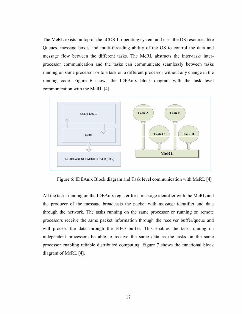
The MeRL exists on top of the uCOS-II operating system and uses the OS resources like
Queues, message boxes and multi-threading ability of the OS to control the data and
message flow between the different tasks. The MeRL abstracts the inter-task/ inter-
processor communication and the tasks can communicate seamlessly between tasks
running on same processor or to a task on a different processor without any change in the
running code. Figure 6 shows the IDEAnix block diagram with the task level
communication with the MeRL [4].
BROADCAST NETWORK DRIVER (CAN)
MeRL
USER TASKS
Figure 6: IDEAnix Block diagram and Task level communication with MeRL [4]
All the tasks running on the IDEAnix register for a message identifier with the MeRL and
the producer of the message broadcasts the packet with message identifier and data
through the network. The tasks running on the same processor or running on remote
processors receive the same packet information through the receiver buffer/queue and
will process the data through the FIFO buffer. This enables the task running on
independent processors be able to receive the same data as the tasks on the same
processor enabling reliable distributed computing. Figure 7 shows the functional block
diagram of MeRL [4].
17

Figure 7: MeRL block diagram [4]
The MeRL is implemented independent of the lower level broadcast network and invokes
a set of well-defined API calls. As long as the network driver is implemented to match
the specifications of the API and is a broadcast type network, the lower level network can
be replaced with no change on the MeRL implementation.
1.6 Embedded Network Selection There are different embedded networks that are available in the market and the design
considerations on the choice of a network for reconfigurable architecture implementation
are discussed in this section. The Ardea framework requires an embedded network for
communicating between the software modules on different processors and also for
18

propagation of system faults, and configuration information. Also the embedded network
should have fault tolerant standards in-built inside the network framework and physical
media should have the ability to communicate under high-noise environments. These
were some of the design considerations in choosing an embedded network for the
implementation of the Ardea network interface task.
Before choosing an embedded network that can be selected, the software architecture
employed by the network standard and the MAC level communication mechanisms are
also taken into consideration. As the Ardea environment will be used safety-critical
applications, the network must be able to provide deterministic communication between
the nodes. Some of the embedded networks considered for implementation are:
1. Controller Area Network [6]
2. Bluetooth [30]
3. Universal Serial Bus (USB) [31]
4. IEEE 1394 [32]
A design matrix is charted to highlight the properties of the embedded networks and their
relative differences are tabulated as shown in Table 1. It can be seen that some of the
networks chosen have high-overhead in the embedded market and requires a personal
computer to monitor the device communication. This makes some of the networks
undesirable for pure embedded system communications.
Bluetooth [30] network has an advantage of communicating wirelessly over longer
distances, but it is a master-slave communication mechanism and the master node
synchronizes and initiates the communications on the bus. This feature makes the
Bluetooth undesirable in safety-critical applications, where a single failure to the Master
would stop the communications on the network. The USB and IEEE 1394 standards are
aimed at interconnecting peripherals with a desktop computer or any other compatible
device and have higher bandwidths but less channel length. The point to point
communication violates one of the principal requirements of the Ardea framework, where
a packet sent by one node should be visible across all the nodes.
19

Table 1: Design matrix for the embedded networks
Property CAN Bluetooth USB IEEE 1394
Physical layer 2 wire
differential
signaling
2.4GHz
Wireless
spectrum
Twisted pair Two
separately
shielded
Twisted pairs
Topology Multi-master
Bus
Master- Slave
Communication
Point to Point
Star, Tree
Peer to Peer
Data Rate 1 MBits/ Sec 1 MBits/Sec 1.5 MBits/ Sec
to 480
Mbits/Sec
98.3
MBits/Sec to
393.20
MBits/Sec
Maximum Number
of nodes in
network
40 7 Active and
125 passive
devices on
network
127 63
Cable length 40 meters 1- 100 m
(depending
upon class of
device)
5 meters 4.5 meters
Typical application Automotive
applications
(soft real-
time)
Personal Area
networks (cell
phones, PDAs,
cameras)
Personal area
networks
Personal
Area
networks,
Automotive
application
(Renault)
Based on the properties from Table 1, Controller Area Network (CAN) is the only
network that can reliably provide communication at higher data rates and also has
inherent fault-tolerant capabilities. The advantages of using Controller Area Network for
implementing reconfigurable architectures are discussed in Section 1.6.1.
20

1.6.1 CAN Advantages CAN has reliable data transfer mechanism and due to its 2-wire differential signaling,
remains unaffected by the Electro Magnetic Interference (EMI) on the channel. As CAN
is a bus-based topology and all the nodes on the network using a message-oriented
protocol resulting in loss-free arbitration of the bus. This ensures high determinacy in
packet transmission/reception and enables use of CAN in real-time applications where
critical deadlines have to be met for packets.
In the CAN bus, the Message Identifier determines both the priority of the message and
the bus access resulting in the higher priority messages having short latency time
regardless of the bus load. The CAN also has active error detection and isolation
mechanisms for erroneous nodes on the bus thereby preventing one faulty node from
disturbing the communication on the bus. If a node exceeds the pre-defined error rates,
then the CAN controller disconnects the node from the bus at run-time and the node can
rejoin the network in case it is once again capable of sending/ receiving packets reliably.
CAN supports bandwidth upto 1 Mbits/Sec for a maximum distance of 40 meters is
higher than any other embedded network considered. CAN hardware is cheaper and
microcontrollers support for CAN is significantly higher than any other embedded
network considered (At least 40 known microcontroller vendors support CAN [5]
hardware).
1.7 Problem Statement This section describes the actual motivation for the thesis research work, the design
constraints and provides a brief overview on the problems that are solved by the thesis
work. The motivation for ENDURA implementation is for the network layer to be
deployed on reconfigurable architectures as network tasks, where the system data can be
reliably communicated between the nodes. The embedded network chosen for Ardea
framework is required to have the ability to efficiently send small payloads, dynamic
registering/unregistering for packets and have real-time application capabilities in-built
on the network framework. Some of the networks that adhere to these criteria are CAN,
21

802.15.4 [33] and ZigBee [34]. The ENDURA layer implementation with CAN requires
that the driver layer adhere to the well defined API prototypes that are exposed to the
higher layers and this will enable higher layers to abstract the network layer below and
invoke the driver APIs for the services required. The ENDURA layer should provide
configuration of the C_CAN controller and also to provide a common platform for
communication between the different sub-systems.
For verification of design and implementation of ENDURA, an UAV application will
have to be tested with a customized implementation. The Auto-pilot communication is
the key to achieving autonomous flight on an UAV and the Auto-pilot used for the CAN
UAV application is a Commercial Off-The Shelf (COTS) Piccolo Auto-pilot. The Piccolo
provides an Extended CAN interface (CAN2.0B) for communicating on the bus and the
rest of the sub-systems on-board the UAV are CAN 2.0A type. Hence the ENDURA
implementation is required to perform the translation of CAN 2.0B packets with 29-bit
message identifiers to the CAN 2.0A format with 11-bit identifiers and vice-versa.
The ENDURA layer should have the ability to send packets either in the CAN2.0A or
CAN2.0B format and be able to receive all the packets that are sent on the network. The
size of the packets can vary from 0 bytes to 8 bytes and the ENDURA layer should
correctly be able to send/ receive all the packets with different payloads. The ENDURA
implementation should expose standard Application Programming Interfaces (APIs) to
the higher level applications and for CAN UAV application the API standard is
mentioned in PAXCAN protocol [21].
Further, the ENDURA layer should be able to meet the minimum performance and
latency requirements for the application. For the CAN UAV application, ENDURA
should be able to send and receive data at least twice as fast as the fastest packet that can
be sent on the network as per the PAXCAN protocol [21]. The ENDURA layer is
required to have limited operating system calls in order to make the driver platform
independent of the operating systems and also for portability across operating systems.
22

23
The full implementation of the ENDURA layer should have fault-tolerant capabilities and
provides reliable communication under noisy environments.
Given the functional requirements expected from ENDURA, the following chapters will
be discussing more in detail on design, implementation and performance details of the
Controller Area Network driver for reconfigurable systems. Chapter 2 discusses the CAN
Physical layers, protocol overview on error detection, packet formats and some CAN
applications and their design. Chapter 3 provides an overview on the hardware that is
available commercially for implementation of CAN and discusses the Microcontroller
support for CAN and the CAN controller details. Chapter 4 documents the functional
requirements, the design decisions, the implementation procedure for ENDURA layer
and fault-tolerant schemes added into the layer. Chapter 5 lists the performance
characteristics that are expected of the network, the results of conformance testing, data
from bandwidth, latency, reliability tests and sporadic packet testing. Chapter 6 shows the
compatibility of the ENDURA implementation with the CAN requirements and provides
the conclusion to the thesis work.
Appendix A provides an overview on the CAN protocol standard and Appendix B
provides an overview on the CAN controller hardware. Appendix C lists the references
that are used for preparing this thesis document.

Chapter 2: CAN Protocol and Applications
This chapter will provide an overview on the CAN Data Link layer, CAN protocol
background information and some popular CAN based applications in use. The CAN
protocol standard specifies only the Data-Link layer and physical layer and the higher
level protocols are not standardized and are application dependent. For implementing an
Ardea reconfigurable architecture, a higher level application layer namely MeRL
(Message Routing Layer) has been developed that controls the binding of message
identifiers with application tasks and also enables seamless passing of tasks / messages
between processors [2].
2.1 CAN Applications CAN is a widely used many industrial applications and this section briefly discusses
some of the popular applications that use CAN. The CAN protocol is a Data link layer
(DLL) protocol and hence a higher level application has to be implemented to control the
communication mechanisms, application specific message identifier tagging, packet re-
transmission and for deterministic system operation. There are different standardized
higher level protocols that are being used to develop applications through CAN. Some of
the well-defined CAN application layers are:
1. CANOpen
2. CAN Kingdom
3. DeviceNet
4. SAE J1939 ( Specific only for Automotive vehicle application)
5. CANAerospace
Besides these higher level protocols, there are many application specific layers that are
being used by the developers for their custom projects. The IDEA Lab at University of
Kentucky uses IDEAnix framework for implementing a reconfigurable architecture
platform. The CAN application layer is the highest level of software that exists on top of
all the protocol specific software layers. Before presenting the custom developed
24

application for CAN some of the well known commercial / Space applications that use
CAN are discussed in following sections.
2.1.1 Vehicle Application: Light Electrical Vehicles (LEVs) Though CAN was primarily developed for Cars and trucks, CAN-in-Automation (CiA)
and EnergyBus are jointly developing an open network for Light Electric Vehicles
(LEVs). The resulting bus is to be named EnergyBus and will control all the electrical
devices present on the vehicle and the design will also include a CANOpen network that
will be used to control all the devices and connecting sensors on the vehicle.
LEVs provide a cheaper and environment friendly mode of travel and can be used for
traveling short distances. The LEV market sector focuses on scooters, bicycles, tricycles,
motor scooters/cycles, commute cars and power-assisted wheel chairs. LEVs range in
size from electric scooters in the smaller segment to up to a one-man car that will use the
High Occupancy Lanes (HOV) on freeways.
2.1.2 Marine Applications: Autonomous/ Manned vehicles Details on some of the application of the CAN on marine projects are discussed in this
section. Research on using local data networks for marine applications has been studied
and implemented in recent years due to advent of new developments in the embedded
network domain. CAN with its high data-rate, availability and built-in error detection
mechanisms make it a highly desirable network standard for any embedded application
requiring local data networks. An Application using CAN for Maritime vehicles is
discussed in the following section.
2.1.2.1 SeaCAN Architecture for Maritime vehicles The SeaCAN architecture is designed and deployed on all new unmanned seaborne
targets by the United States Navy to aid in its maritime applications. The design includes
an Auto-pilot which controls a closed loop over the network and monitors the GPS
receivers/ Rudder Feedback nodes/Pitch-Roll-Heading, throttle control modules and
Command/ control modules. The SeaCAN architecture is implemented on a number of
25

Infineon C167 microcontrollers, connected through CAN. The entire system is run at a
speed of 125KBits/Sec and lower speed is considered for scalability for larger boats and
longer bus lengths. The Software environment consists of CAN Kingdom architecture
and an Operating system with support in-built for CAN.
2.1.3 Space Applications: CANAerospace CAN 2.0 A/ B implementation is an event-based protocol and as such cannot be used in
the aerospace industry requiring higher reliability and safety constraints. Hence a version
of the CAN higher level layer called CANAerospace was developed by Stock Flight
systems to provide higher reliability in communication between the nodes on a
distributed space applications. CANAerospace is a light weight protocol which consists
of 5 basic message types and each with its own message identifier range and priority [12].
A Space application design using CAN is discussed in following section.
2.1.3.1 SMART-1 Spacecraft Small Missions for Advanced Research in Technology (SMART-1) was the first space
craft developed by European Space Agency to travel to the moon and was launched in
September 2003. SMART-1 space craft system is divided into 2 major modules: System
module for controlling the SMART-1 and another to control the space applications. Each
of the module uses a different system CAN bus (System CAN and Payload CAN) for
communications and are controlled by two redundant CONA-A and CONA-B.
For making the system more robust, all the modules in the system are redundant
including the CAN buses. Each CAN bus has one normal path and a redundant path of
communication and the system controller can choose at any time to switch from the
nominal CAN bus to redundant bus. Besides this, all the nodes also look for life sign
message on the network and if the life-sign message wasn’t received within certain
duration, then the nodes switch from the nominal to the redundant bus. In order to reduce
the bus errors due to radiation, radiation hardened CAN controllers were developed and
deployed. SMART-1 successfully was launched on September, 2003 and after 3 years of
26

monitoring the lunar surface reached the end of its mission on September, 2006 by a
mini-impact with the lunar surface.
2.2 CAN Protocol Specification This section provides an overview on the structure of the protocol specifications and the
details on the different physical layers available. The International Standards
Organization (ISO) had released the specification standards for Controller Area Networks
under CAN 2.0A for Normal 11 bit identification packets and CAN 2.0B for Extended
CAN with 29 Bit identifiers for packets. For the purposes of compatibility between
different implementations of the CAN, the realizations of the CAN should meet the CAN
2.0A [6] or CAN 2.0B [7] standard.
The protocol is based on the OSI “Reference Model” for data communication and the
CAN protocol is standardized mainly in the Data Link Layer – Logical Link Control
(LLC) Sub-layer and Medium Access layer (MAC) and to an extent on the physical layer.
The protocol standard is broadly classified into 3 layers
1. The CAN object layer
2. The CAN transfer layer
3. The physical layer
Layers 1 and 2 together act as the Data-Link Layer of the OSI model and Physical layer
implementation is the actual bit transmission and bit timing schemes. The following
sections will explain some of the layers in more detail. The Can transfer layer represents
the kernel for the CAN protocol and the functionality of the CAN Transfer layer is
implemented mostly in hardware. This implies that the CAN transfer layer offers limited
flexibility and please refer to Appendix A: CAN Protocol S for more information on the
functionality of the CAN Transfer layer.
27

2.2.1 CAN Physical Layer The physical layer is the lowest and the medium where messages are transmitted between
nodes. The physical layer defines parameters such as the signaling schemes, electrical
levels, cable impedance and cable termination parameters [8] and this section provides an
overview of the CAN physical layers and describes some of the properties of these layers.
There are several different physical layers that can support the operation of Controller
Area Network. Some of them are listed below
1. CAN Standard ISO-11898-2
2. CAN Standard ISO-11898-3
3. SAE J2411
4. Time Triggered CAN ISO-11898-4
5. Modifications of RJ485 connectors were also in use
Besides these physical layer standards, there are several proprietary physical layers that
are in existence. The different physical layers cannot interoperate between each other due
to the difference in the signaling schemes, bit-timing methodology and the type of
electrical signals used and hence the physical layer must be the same for all the nodes
within the same network for communication to be possible except for CAN standard ISO-
11898-2 and CAN standard ISO-11898-3 where transceivers on the same bus could
interoperate in some cases [8].
The CAN Standard 2.0 A/ B does not define the Physical layer requirements for the CAN
layer letting the application designers customize the signaling and the bandwidth
constraints. Refer APPENDIX A for more information on CAN physical layer details.
2.2.2 CAN Bit timing for the Physical Layer The need for Bit timing in CAN and properties on configuring the Bit-timing registers,
parameters that are included in Bit-timing calculation are discussed in this section. As the
arbitration among nodes is based on the message identifiers, the calculation of bit-timing
is crucial in establishing reliable communication between the nodes. This section
28

provides the various components that compromise a bit sampling time and its calculation
strategies. CAN physical layer uses synchronized transmission at the bit-level and
continuous bit-wise resynchronization is required rather than frame-wise synchronization.
The CAN specification 2.0A/ 2.0B states that the physical layer should have identical bit-
timing for all nodes within the same network.
Each node has its own clock and with no separate clock for synchronization on the
network and the nodes depends on the bit-timing mechanisms to co-ordinate the data
transmission. As the network uses Non-Return to Zero (NRZ) encoding, the CAN
transmitter adds an extra bit after 5 successive bits of same polarity and the receiver
removes these stuffed bits from the packet during decoding. Reception of 6 successive
bits of same polarity is considered as an error in transmission and has to be retransmitted.
Nominal bit time is the number of bits that can be transmitted on the bus per second
without the hard synchronization of the clocks on ideal transmitters. The nominal bit time
is classified into 4 non-overlapping time segments. Refer APPENDIX A for more
information on the exact parameters that control the bit-timing for the CAN protocol.
2.2.2.1 CAN Bus Arbitration
. Controller Area Network is a message-based, broadcast network and the packets
transmitted on the bus can be received by all the nodes present on the bus. This section
explains the concepts involved in CAN bus arbitration and resolving simultaneous
transmission of data by two nodes Since there is no mechanism to detect packet collisions
(due to asynchronous start of packet transmission by the nodes) like in Carrier Sense
Multiple Access-Collision Detection (CSMA-CD) or to avoid collisions like Carrier
Sense Multiple Access-Collision Avoidance (CSMA-CA), CAN uses a decentralized
contention-based bus arbitration to break collisions on the network.
The CAN arbitration field consists of an 11 bit frame identifier (In case of CAN 2.0B, the
frame identifier field is 29 bits) and a Remote Transmit Request (RTR) bit. Whenever
nodes start transmitting simultaneously, bit-wise non-destructive arbitration is used to
29

break the conflict on the bus. The Most Significant Bit (MSB) of the frame identifier is
transmitted first. The network behaves like a Wired-AND logic with the Recessive Level
at +5V and the Dominant level at 0V. All the nodes transmit a Recessive bit as long as
the nodes are idle and the bus is at a Recessive state. Start of Transmission is indicated by
the transmission of a Start-Of-Frame (SOF) bit on the network (Dominant Level).
All the transmitting nodes compare the transmitted bit level with the signal level on the
bus. If a node transmits a Recessive Level and observes that signal level on the bus is
Dominant, the node stops transmitting the packet immediately (as there is at least one
transmitting node with lower message ID) and enters the listening mode. It waits for the
other transmitting node(s) to complete the packet transfer and waits for the intermission
bit fields to start transmitting again. The state diagram for the Packet transmission,
arbitration and reception is shown in Figure 8. For the bit-wise arbitration based on
Message Identifiers to work, it is assumed that no two nodes can start transmitting packet
frames for the same id with non-zero payload and this constraint is adhered to, during the
system design phase.
30

Figure 8: State Diagram for CAN Engine
31

2.2.2.2 CAN Frame Formats
The different packet formats that can possibly be sent on the network are discussed in this
section in detail. Some of the packets are sent only during special conditions (mostly for
error conditions) and typically majority of the packets that are sent on the network are
normal CAN data frames. CAN 2.0A/B Standard specifies that there are 4 different type
of CAN Frames that can be found during the lifetime of the network.
1. CAN Data Frame
2. CAN Remote Request Frame
3. CAN Error Frame
4. CAN Overloaded Frame
CAN Data Frame
CAN Data Frame is the format in which data is sent from transmitter to the receiver. It is
initiated by the source and can be received by one or many nodes depending on the
configuration of the receiving nodes. Figure 9 shows the different fields within a CAN
data frame and Table 2 describes the individual fields on the CAN data frame.
Figure 9: CAN Data Frame Format
32

Table 2: CAN frame format for a basic CAN 2.0A frame
Parameter Name No. of
bits
Description
Start of Frame
(SOF)
1 bit Single dominant bit (0V)
Message Id
(Mesg. Id)
11 bits
or
29 bits
11 or 29 bit message identifier is used to
identify the packet on the network and the
message identifiers are transferred in Big
Endian Format (MSB->LSB).
Remote Request
(RTR)
1 bit Remote request bit is sent when a node requires
a packet from any other node on the network. In
RTR request, RTR bit is set to 1 and in RTR
response, RTR bit is zero.
Control Field
6 bits The least significant 4 bits are reserved for Data
Length Code (DLC) to indicate the size of
payload (maximum 8 bytes)
Data Field 64 bits This field contains the payload data that is to be
sent on the network. Maximum payload 8 bytes.
Cyclic redundancy
check (CRC)
15 bits Contains a 15 bit CRC sequence value
CRC Delimiter 1 bit This field is used to indicate end of CRC field
Acknowledgement
field (ACK)
2 bits The transmitter sends 2 bits one for ACK slot
and one as ACK delimiter. All the receivers on
successful reception of packet after CRC check
respond within the ACK slot by overriding the
ACK Slot Recessive bit with a Dominant Bit.
End of Frame
(EOF)
1 bit End of Frame is indicated by a flag sequence of
7 Recessive Bits
33

CAN Remote Frame
Any Node on the network can request for a message ID from the data source of the
identifier by having the Remote Transmit Request (RTR) bit set to 1. The Control field
(Data Length Code) should match the packet length expected by the Request Initiator and
the rest of the packet is same as that of the generic CAN data frame.
The data source of the message ID responds with a CAN Data Frame with the Remote
Request Bit set to 0. As the RTR bit is the last bit in the arbitration field of the frame, the
Remote Request frame has a lower priority than a Data Frame on the network. A Remote
Request frame format is shown in Figure 10.
SOF
MESSAGE ID 11 or 29 bit
RTR
CONTROLFIELD6 bits
DATA FIELD 0 – 8 bytes
CRC15 bits
CRC
DLMT
ACK
SLOT
ACK
DLMT
EOF7
1-bits
ID10
ID9
ID0
ID1
ID2
RTR
RSRV1
RSRV0
DLC3
DLC0
DLC1
DLC2
THE MESSAGE ID HAS 29 BITS
IN CASE OF CAN2.0B
...RTR BIT
SET TO 1 FOR REMOTE REQUEST
FRAME
Figure 10: CAN Remote Request Frame
34

CAN Error Frame
In the CAN Data Frame, the ACK Slot is set to Recessive (+5V) by the first recipient of a
complete packet after CRC Checksum and there is no guarantee that the other nodes on
the network have received the packet correctly. So, any node on the network that did not
receive a packet ( Normal Data Packet, Remote Transmit Request or Overloaded packet)
correctly could signal the transmitter by using a CAN Error Frame.
The CAN Error Frame deliberately breaks the Bit-Stuffing rules for the network by
sending 6-bits of same polarity and causes the transmitter to retransmit the data.
Detection of error during transmission or after reception of an error frame or overloaded
frame generates a new error frame. The generic Error Frame format is shown Figure 11.
INTERFRAME SPACE
ERROR FLAGS VIOLATING BIT-STUFFING
6-12 bits
8 BIT ERROR DELIMITER
Figure 11: Error Frame Format
CAN Overload Frame
This section provides an overview on the CAN overload frame, the circumstances when
the Overload frame is sent and the response of the nodes on the networks. The CAN
Overload frame can be transmitted under two conditions
1. Request Overload frame – requesting for delay in next data
2. Reactive Overload frame – due to errors in intermission field
The CAN Request Overload frame is allowed to be transmitted only during the first bit of
the transmission of a new data frame and can be used to delay the data frame by at most
two frames. The CAN Reactive Overload frame is transmitted to indicate special
35
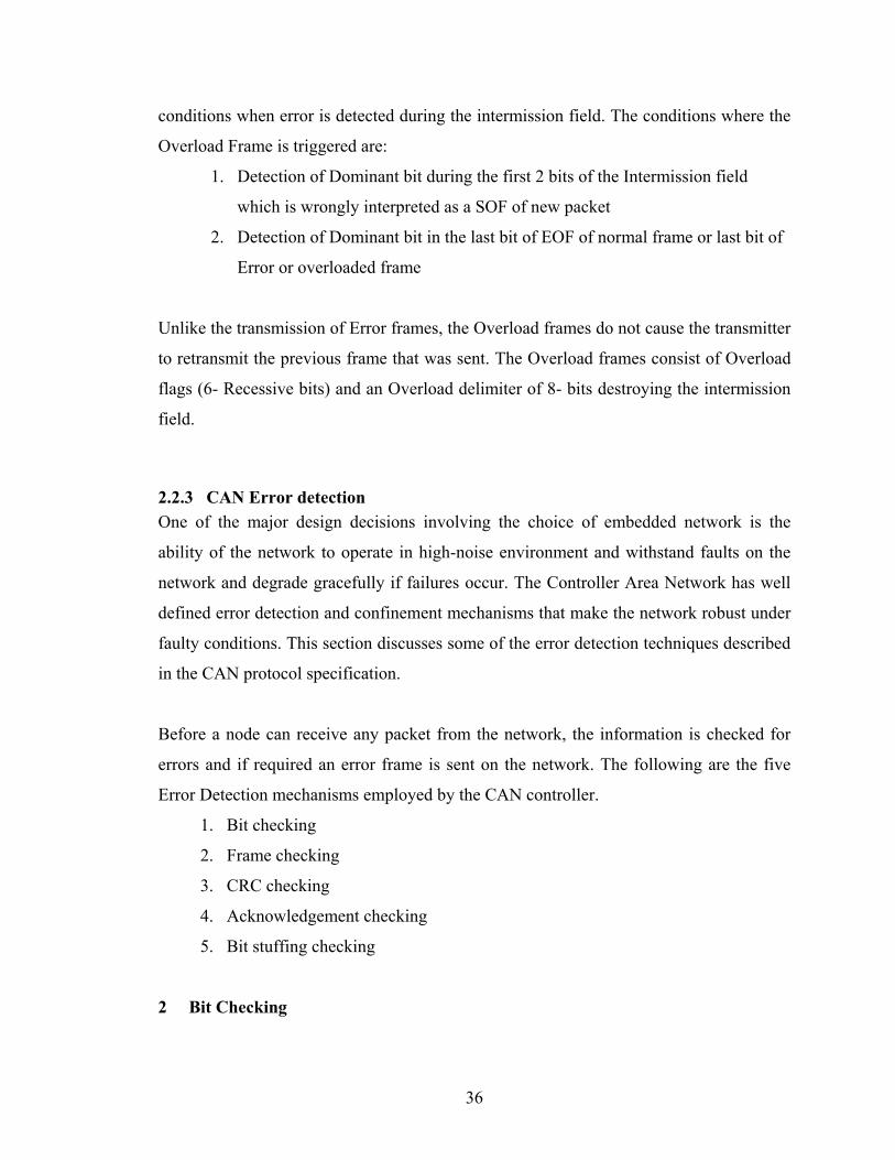
conditions when error is detected during the intermission field. The conditions where the
Overload Frame is triggered are:
1. Detection of Dominant bit during the first 2 bits of the Intermission field
which is wrongly interpreted as a SOF of new packet
2. Detection of Dominant bit in the last bit of EOF of normal frame or last bit of
Error or overloaded frame
Unlike the transmission of Error frames, the Overload frames do not cause the transmitter
to retransmit the previous frame that was sent. The Overload frames consist of Overload
flags (6- Recessive bits) and an Overload delimiter of 8- bits destroying the intermission
field.
2.2.3 CAN Error detection One of the major design decisions involving the choice of embedded network is the
ability of the network to operate in high-noise environment and withstand faults on the
network and degrade gracefully if failures occur. The Controller Area Network has well
defined error detection and confinement mechanisms that make the network robust under
faulty conditions. This section discusses some of the error detection techniques described
in the CAN protocol specification.
Before a node can receive any packet from the network, the information is checked for
errors and if required an error frame is sent on the network. The following are the five
Error Detection mechanisms employed by the CAN controller.
1. Bit checking
2. Frame checking
3. CRC checking
4. Acknowledgement checking
5. Bit stuffing checking
2 Bit Checking
36
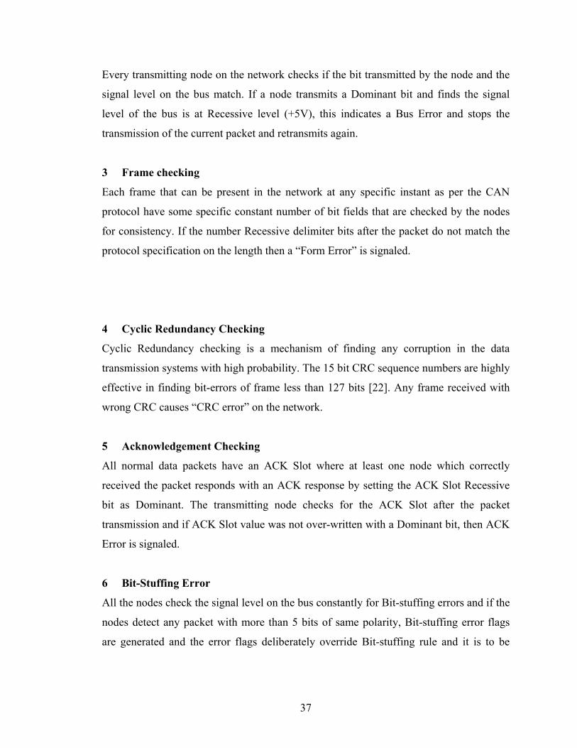
Every transmitting node on the network checks if the bit transmitted by the node and the
signal level on the bus match. If a node transmits a Dominant bit and finds the signal
level of the bus is at Recessive level (+5V), this indicates a Bus Error and stops the
transmission of the current packet and retransmits again.
3 Frame checking
Each frame that can be present in the network at any specific instant as per the CAN
protocol have some specific constant number of bit fields that are checked by the nodes
for consistency. If the number Recessive delimiter bits after the packet do not match the
protocol specification on the length then a “Form Error” is signaled.
4 Cyclic Redundancy Checking
Cyclic Redundancy checking is a mechanism of finding any corruption in the data
transmission systems with high probability. The 15 bit CRC sequence numbers are highly
effective in finding bit-errors of frame less than 127 bits [22]. Any frame received with
wrong CRC causes “CRC error” on the network.
5 Acknowledgement Checking
All normal data packets have an ACK Slot where at least one node which correctly
received the packet responds with an ACK response by setting the ACK Slot Recessive
bit as Dominant. The transmitting node checks for the ACK Slot after the packet
transmission and if ACK Slot value was not over-written with a Dominant bit, then ACK
Error is signaled.
6 Bit-Stuffing Error
All the nodes check the signal level on the bus constantly for Bit-stuffing errors and if the
nodes detect any packet with more than 5 bits of same polarity, Bit-stuffing error flags
are generated and the error flags deliberately override Bit-stuffing rule and it is to be
37

38
noted this error flags also cause all the other nodes to generate an error frame for the
packet.
Error detection mechanism is capable of identifying all global errors across the bus and
also all local errors at transmitters. The mechanism is also capable of detecting up to 5
randomly distributed errors in a message, bursts of packet with length less than 15 or odd
number of bits in a packet. The message Error rate is proportional to the frame length of
the packet and hence the undetected message probability is significantly higher for
CAN2.0B (Extended frame format) than the CAN2.0A standard. Appendix A: CAN
Protocol S provides more information on fault tolerant mechanisms within the CAN
protocol.

Chapter 3: CAN Hardware This Chapter provides a review on the hardware available on the market that provide
CAN support and also discusses in detail the microcontrollers with CAN capability and
C_CAN CAN Controller module architecture and configuration steps. The CAN
hardware is supported widely by different manufactures and the entire list of the
manufacturers is listed in [5].
3.1 CAN Hardware Properties: A large number of vendors provide CAN hardware and the ready availability of hardware
support makes CAN ideal for quick development. The different CAN hardware includes
CAN controller chips, Transceivers, Repeaters, bridges and Gateways and the hardware
properties of these devices are described in Sections 3.1.1 through 3.1.5.
3.1.1 CAN Controller Chips The CAN controller is responsible for communication on the bus as per the CAN 2.0A/B
protocol and also for maintaining the fault detection and confinement on the bus. This
section explains some of the functionality of the CAN Controller chips and the different
CAN controller chips available in the market are listed. The bit rates can be programmed
up to a speed of 1MBits/sec for a bus length of up to 40 meters. But for actual connection
to the physical layer, CAN Transceiver chips are needed. Some of the CAN Controller
chips available in market are:
1. C_CAN chip from Robert Bosch
2. 82527 from Intel Technologies
3. MCP2150 from Micro-chip
4. SJA1000 Philips
3.1.2 CAN Transceiver chips CAN transceiver chips provide an abstraction of the physical layer to the CAN controller
chips and also provide mechanisms for electrical isolation of the microcontroller from
network. The CAN transceiver consists of a transmitting amplifier and a receiving
39

amplifier. The transmitting amplifier is responsible for providing sufficient driver output
capacity and also for preventing on-controller driver from overloading and Electro
Magnetic Interference (EMI) reduction. The receiver amplifier is responsible for
maintaining the defined recessive signal level on the bus and also for protecting on-chip
input comparator from the voltage surges on the bus. CAN transceivers also detect shorts
and line breakage on the bus.
3.1.3 CAN Repeaters CAN Repeaters are passive components that are added to the bus line to increase the
length of the bus. But addition of CAN Repeaters on the bus increases the signal
propagation time on the line. The Repeaters split the bus into two physically separate
electrical segments but are still treated as one logical entity.
3.1.4 CAN Bridges CAN Bridges connect two logically separate networks on the Data Link Layer level and
the CAN message IDs are different in each of the separate segments. CAN Bridges are
used for defining packet forwarding mechanisms between the networks and can be used
to forward packets or part of packets in an independent time-delayed mode. CAN Bridges
differ from the Repeaters that they forward packets from one network to other, unlike
amplifying the signal like the Repeater. Also Bridges forward packets from two logically
separate networks unlike the Repeaters.
3.1.5 CAN Gateways CAN Gateways are used to connect two networks with different higher level protocol and
the translation of information occurs at the Layer 7 of the OSI framework. CAN
gateways provide a mechanism for accessing the network through other communication
protocols.
3. 2 CAN Microcontrollers Overview Microcontrollers provide the development environment for implementation of ENDURA
layer and also for higher level protocols over the CAN controller chips. This section
40

provides an outline on the capabilities of these microcontrollers from the CAN point of
view. Different families of microcontrollers are available in the market with CAN
support and can also be customized as per the application. Most of these microcontrollers
differ in the number of hardware message objects supported by the board and also on the
main processor family. Some of the processor families available on the boards are:
1. 8051 family
2. C16x/ST 10/ XC16x family
3. ARM 7/9 family
4. Cortex M3 family
Microcontrollers with CAN support generically either have an On-chip CAN controller
or can be integrated into the board as a stand-alone device. Some of the Microcontrollers
with varied processor families and CAN controllers are analyzed in Sections 3.2.1
through 3.2.3 (from CAN perspective).
3.2.1 Silicon Laboratories The Silicon Labs provides CAN support in their Chipset models: C8051F04x and
C8051F06x. The C8051F04x family is a fully integrated system-on-chip 8051 core
microcontroller and can execute at 25 MIPS (Millions of Instructions Per Second). The
C8051F04x development board is integrated with an on-board C_CAN controller chip
from Robert Bosch Gmbh and supports up to 32 message objects [17], each with its own
individual message identifier mask and can be configured in either Receive or Transmit
mode. The C8051F04x supports both CAN 2.0A and CAN 2.0B and a maximum
bandwidth of 1 MBits/S.
3.2.2 Infineon Technologies Infineon Technologies provides the most extensive CAN support and manufactures
different families of microcontrollers in 8-bit or 16-bit or 32 bit processors with
integrated CAN controllers. This section analyzes the microcontrollers that exist in the 8-
bit, 16-bit and 32-bit processors.
41

3.2.2.1 8051 Family: C500 series (8-bit) C500 Series of Microcontrollers consists of a fully compatible 8051 core processors and
an On-chip CAN controller with support for CAN 2.0A and CAN 2.0B and supports a
maximum speed of 1 MBaud when the operating frequency is greater than 8 MHz. The
CAN Controller has upto 256 register/ data bytes located in the external RAM and upto
16 message objects can be configured for sending and receiving packet information [13].
3.2.2.2 8051 Family: XC88x series (8-bit) XC88x series is an enhanced version of the 8051 based core and has extensive
networking capabilities due to an on-chip multiCAN controller and an on-chip LIN
Bootstrap loader [14]. The On-chip CAN Controller handles the networking tasks
specific to the higher level CAN layers and reduces the load on the main processor. The
multiCAN controller has 2 CAN nodes and 32 message objects are shared among both
the nodes. XC88x provides support for connecting to CAN gateways.
3.2.2.3 16-bit Microcontroller (C161 Series) C161 Series microcontrollers use high performance 16-bit core microcontrollers and
capable of running at peak speeds of 12.5 MIPS. The C161 series consists of an
integrated CAN module with CAN 2.0B support that can send and receive packets in
either 11 bit or 29 bit message identifiers. Fifteen message objects are available for
configuration by the software and the Message object number 15 can be configured
explicitly to support only CAN 2.0A [16]. Like the other Infineon processors, the
maximum bandwidth supported is 1 M Baud. In C161-CS, there are 2 CAN modules and
they can be configured individually and have separate interrupt nodes.
3.2.2.4 32 bit Microcontrollers (XC2200 Series) XC2200 series employ a high performance 32-bit processor core and consists of an On-
chip MultiCAN controller which can support upto 6 different CAN nodes on a single
processor. There are 256 different message objects [16] that can be configured
individually and supports CAN 2.0A and CAN 2.0B standards at maximum bandwidth of
42

1M Baud. XC2200 Series provides support for Gateway interfacing of CAN networks
and also has support for FlexRay [18] communications.
3.2.3 Texas Instruments Texas Instruments manufactures higher end microcontrollers with ARM processors and
with high-end Can controllers. This section reviews the ARM based microcontrollers
from Texas Instruments.
Texas Instruments TMS470R1x series of Microcontrollers use a 16 / 32-bit ARM 7
TDMI RISC core processor as the main controller. The Microcontroller may contain
either of the two variants of the CAN controller namely a Standard CAN Controller
(SCC) or a High-End CAN Controller (HECC). Both the controllers use CAN Protocol
Kernel (CPK) module for controlling the protocol tasks and SCC or HECC differ only in
their message control mechanisms. SCC has 16 message Objects and 3 receive identifier
Masks and HECC has 32 message objects and 32 receive identifier Masks [19]. The
maximum bandwidth that is supported by the CAN controllers is 1 MBits/ Sec at 8 MHz
system clock. HECC is also compatible for the software written for SCC.
3.2.4 Design Choice of Microcontroller After careful comparisons of different microcontroller chipsets and tool chains, Silicon
Laboratories C8051F040 board is chosen as the preferred development platform for
implementation of the Controller Area Network layer for Reconfigurable Embedded
Systems.
The ease of availability of Cross-compilers (Keil, SDCC), tool chains, cost of obtaining
evaluation boards and prior working experience with other 8-bit microcontrollers from
Si-Labs made the Silicon Laboratories a better option over other microcontrollers. The
Si-Labs C8051F040 board uses an integrated C_CAN processor and the
structure/operations of the C_CAN processor are described in Section 3.3.
43
3.3 C_CAN Controller Overview C_CAN controllers are used for CAN communications in C8051040 boards that are
chosen for implementation of ENDURA and this section provides an overview of the
structure of the C_CAN controller. The C_CAN controller can be used as a stand alone
module or can be integrated as a part of an ASIC [20]. C_CAN controller can be
configured to communicate as per the CAN 2.0A or CAN 2.0B (Extended CAN) protocol
and can be configured for communicating with bit rates upto 1 MBits/Sec. There are 32
message objects that can be individually configured for message transmission or
reception and all the message objects have their own individual identifier mask.
3.3.1 C_CAN Engine The CAN Engine can be configured through an 8-bit module interface or 2 16-bit ARM
AMBA APB bus. The main components of a C_CAN Controller are:
1. CAN Core
2. Message RAM
3. Message Handler
4. Module Interface
3.3.1.1 CAN Core This section provides an overview on the CAN Core that runs the CAN Kernel and also
has a Receive/ Transmit shift register for serial/parallel conversion of the packets on the
bus. The CAN Core has to be initialized before the node can start communicating through
the controller. The controller cannot be initialized at run time and any initialization can
take place only after a reset of the controller. During the initialization phase of the
controller, the Init bit of the CAN control register is set to 1 and the Bit timing register
and BRP Extension register has to be set with their corresponding values.
When the Init bit is cleared from the CAN control register, Bit Stream Processor (BSP)
waits for 11 recessive bits for synchronizing with the data transfer with the bus. The CAN
Engine can communicate with the bus only after this synchronization has been
established. For more information on the modes at which the CAN engine can be run
refer to Appendix B.
44

3.3.1.2 Message RAM The Message RAM within the CAN engine are the locations where the message objects
and the Identifier masks are stored. The message objects are analogous to the hardware
buffers available on the Network Interface Cards (NIC) and the number of message
objects present on the controller provides the flexibility to the software driver for
configuration specific to receive or transmit purposes.
There are 32 message objects that are present in the Message RAM and each with its own
identifier mask. The significance of the identifier mask for each of the Message object is
that, each message object can be configured to receive or transmit a frame with message
Id or a ranges of message Id that are different from the other message objects. Hence it is
possible to have 32 different configurations for the sending and receiving packets.
3.3.1.3 Message handler The message handler is the state machine that controls the transfer of information
between the Message RAM and the Receive /Transmit shift register that is present in the
CAN Core. The state machine is also responsible for generation of the interrupts (after
successfully receiving/ transmitting a packet or due to error conditions) as per the
configuration of the control / configuration registers.
3.3.1.4 Module Interface The C_CAN processor can be interfaced through any of the 3 interfaces made available.
The processor has an 8-bit interface for communication with the family of processors that
have 8-bit address bus and two 16-bit interfaces for communication with processors that
have 16 bit address bus. The Silicon Laboratories C8051F04x & C8051F06x interface
with the controller through the 8-bit interface.
3.3.2 C_CAN Registers The C_CAN processor is accessible to the software for configuration and behavior
control (CAN engine and the message RAM) through the registers provided by the
45

processor. This section provides an overview on the C_CAN registers and the
functionalities of the registers that are stored in the Message RAM. The registers reside in
the 256 bytes of addressable memory space of the processor and all the registers are 16
bit wide with the high-byte at the odd address and low-byte at the even address. C_CAN
Registers are classified based on their control properties.
1. Protocol Control Registers
2. Message Interface Registers
3. Message Handler Registers
3.3.2.1 Protocol Control Registers An overview on the Protocol control registers and the functionalities provided by the
registers are discussed in this section. The protocol control registers are responsible for
setting the different modes of operation on the CAN controller, controlling the Global
enable/ disable scheme for the error, interrupts, change configuration and Test registers.
The Protocol control registers also provide status interrupts on Tx/Rx, error
active/passive, Warning and bus off information and also configure the bit-timing
registers. For a list of protocol registers and their operation refer Appendix B: C_CAN P
and C_CAN processor User manual [20].
3.3.2.2 Message Interfacing Registers An overview on the CAN message interface registers and their functionalities are
discussed in this section. The transfer of data from the Message RAM and the CAN
Engine is controlled by a set of 2 interface registers. The interface registers are used to
avoid conflicts between the RAM and the CAN Engine communication and between
transmit block and receive block of the message handlers. The 2 sets of the interface
registers are identical in function and the advantage of the duality of registers is that they
can be used separately for buffering transmitted and received information. This also
enables transmit and receive tasks to interrupt each other and this feature is helpful in
handling high-priority message reception/ transmission. For a list of message interfacing
46

47
registers and their operation refer Appendix B: C_CAN P and C_CAN processor User
manual [20].
3.3.2.3 Message Handler Registers The Message handler registers that are provided as a mechanism by the message handler
to view the status of the message objects that are configured and as a result the registers
are read-only & 4 bytes wide. The message control values can be set/clear by updating
the values of the corresponding message interface registers for the specific message
object. For a list of message handler registers and their operation refer Appendix B:
C_CAN P and C_CAN processor User manual [20].

Chapter 4: ENDURA Design & Implementation Details This chapter provides an overview on the ENDURA layer design and implementation
details for reconfigurable embedded systems. The ENDURA layer has been designed
with an objective to provide the reconfigurable architectures the ability to propagate
status, configuration and error messages between nodes seamlessly. In order to test the
validity of the driver design, an application using Unmanned Aerial Vehicle is taken as
an example platform for implementation of ENDURA. The base design from ENDURA
layer can be customized for any reconfigurable application desired and the corresponding
fault-tolerant schemes are highlighted where required.
To achieve portability and application independence, any software developed for the
Unmanned Aerial Systems from the Intelligent Dependable Embedded Architecture
(IDEA) Lab at University of Kentucky uses the IDEAnix [4] framework as the base
platform. The Network driver has been designed to work seamlessly with the IDEAnix
framework and the design & implementation of the network driver are discussed in detail
in this chapter.
4.1 Special Function Register Access in C8051F04x Processors The Special Function Registers (SFRs) configuration on the C8051F04x boards provides
mechanisms to control and communicate with the 8051-core processor peripherals and
resources. The C8051F040 board has the upper 128 bytes of data RAM (0x80-0xFF)
configured as Special Function Registers (SFRs) [17]. These memory locations can be
accessed either direct addressing (to refer to SFRs) or can be addressed indirectly (to
access data).
The SFRs having addresses ending with 0x0 or 0x8 are bit or byte addressable. The C51
processor maps the addresses (0x80-0xFF) with a paging scheme so that many SFRs can
be mapped into the available memory of 128 bytes. C8051F040 board uses 5 SFR pages
0, 1, 2, 3, F and these pages can be selected using a selection register SFRPAGE.
Read or write to any of these SFR registers can be achieved through the following steps:
1. Load the SFRPAGE with the appropriate page number containing the SFR
2. Use direct addressing to write or read values into the register
48

Some of the C_CAN processor registers are mapped on to the SFRs and they can be
directly addressed to control the registers on the C_CAN processor. The registers that can
be accessed directly/indirectly are: (All the CAN registers are in SFRPAGE 0x1)
1. CAN Control Register (CAN0CN)
2. CAN Test Register (CAN0TST)
3. CAN Status Register (CAN0STA)
All the other CAN registers are accessed indirectly through the other CAN SFR registers.
The other CAN Registers are:
1. Register containing the address of the CAN Register (CAN0ADR)
2. Register to read/write the higher 8 bits of data on the CAN register
(CAN0DATH)
3. Register to read/write the lower 8 bits of data on the CAN register
(CAN0DATL)
The CAN0ADR is loaded with the index appropriate to the CAN register and the
CAN0DATH & CAN0DATL is used to write/read values on the CAN register. For index
values 0x08 – 0x12 (Interface register 1) and 0x20 – 0x2A (Interface register 2), the
CAN0ADR is auto-incremented by 1 to point to the next CAN Register when the data is
read/ written into CANDATL register.
4.2 ENDURA Design This section explains the design details on the different components that make up the
ENDURA layer and also the functional details of the various modules. The Controller
Area Network driver design involves configuration of the C_CAN processor,
initialization of the CAN Engine, setting up the message objects for the required Tx/Rx
set-up, management of message id registering/ unregistering and maintaining software
buffers in the C8051F040 processors.
The block diagram in Figure 12 shows the framework for an application to run using the
IDEAnix on an UAV. The ENDURA layer exposes a set of well defined APIs for the
49

IDEAnix to invoke and handles the interrupts from the C_CAN processor as per the
interrupt configuration.
The Silicon Laboratories (Si-Labs) C8051F040 processor executes all the driver level
code and allocates all the memory required for buffers and data storage on the data RAM
of the processor. The Si-Labs processor interacts with the C_CAN processor through the
address and data bus interface provided by the C_CAN processor. The address and data
bus are 8-bits wide and the module interface for the C_CAN processor receives these
requests/inputs and passes the requests to the respective module.
50

Figure 12: Block Diagram of CAN Application
The CAN Core interacts with the CAN Transceiver through the CAN_RX and CAN_TX
pins and in turn controls the values in and out of the CAN bus. The ENDURA layer has
been split into modules based on their functionalities as Initialization module, Register
module, Unregister module, Get Message module, Send Message module and Translation
51

module. Figure 13 shows the interaction between modules within ENDURA and the
registers read/written on the C_CAN processor by each of the modules.
Figure 13: CAN Module block diagram
4.2.1 Initialization Module This module is responsible for the initialization of the C_CAN processor and is invoked
before any other module from the ENDURA layer could be used. The CAN Core within
52

the C_CAN processor has to be initialized during a Reset or Power ON before any of the
CAN related communication can begin on the network for the node.
The Bit-timing register and the Baud Rate Pre-scaler (BRP) register have to be
configured with the appropriate value for the bus to ensure the correct flow of data. If
Bit-timing and BRP registers are not set correctly with the appropriate value,
communication at the expected bandwidth cannot be possible. Figure 14 shows the
initialization sequences and the registers to be configured (with corresponding Pseudo
code).
4.2.1.1 API Prototype exposed Void Init_network(void);
4.2.1.2 Configuration Steps in Initialization Module The Controller Area Network Transmit pin on the C8051F040 board by default is Open
drain and CAN_TX pin has to be enabled as Push-Pull to enable communication on the
network. The digital cross-bar on the C8051040 board also has to be enabled for the low
ports to become active and available for communication. XBR registers [17] are used to
control the port I/O through the crossbar configurations. For the above configuration,
XBR2, XBR3 registers are manipulated.
SFRPAGE = 0xF (SFR page for configurations)
XBR2 = XBR2 | 0x40 (Setting bit number 6 to enable the
crossbar)
XBR3 = XBR3 | 0x80 (Enable the CAN_TX pin to Push-pull
by setting bit number 7)
Hardware reset does not reset any of the values stored on the Message RAM of the
C_CAN processor and have to be cleared by the software during the initialization phase.
SFRPAGE = 0x1 (CAN0PAGE)
CAN0ADR = 0x09 (Interface register 1 –Command Mask)
53
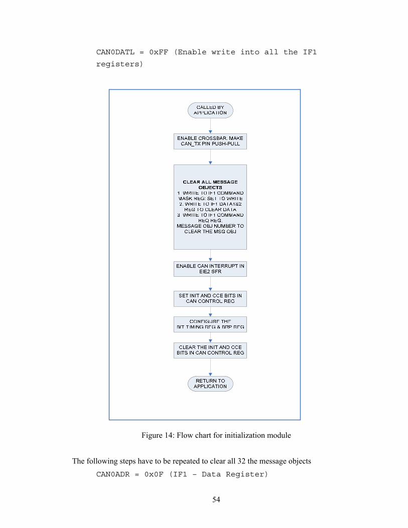
CAN0DATL = 0xFF (Enable write into all the IF1
registers)
Figure 14: Flow chart for initialization module
The following steps have to be repeated to clear all 32 the message objects CAN0ADR = 0x0F (IF1 – Data Register)
54
CAN0DATH = 0x00 (clearing bytes 2-3 of data reg)
CAN0DATL = 0x00 (Clearing bytes 0-1 of data reg)
Address is auto-incremented to CAN Data Register B1 and B2 CAN0DATH = 0x00 (clearing bytes 6-7 of data reg)
CAN0DATL = 0x00 (Clearing bytes 4-5 of data reg)
CAN0ADR = 0x08 (IF1 – Command Request)
CAN0DATL = 0x01 (Message Object Number)
Once the Command Request value is written with the Message object number, the
CANDAT register values are automatically transferred to the message objects in Message
RAM. CAN interrupts have to be enabled on the C805104x core to check for the
interrupts coming from C_CAN processor.
EIE2 = 0x20 (Enable CAN related interrupt)
SFRPAGE = 0x1 (CAN PAGE)
CAN0CN = 0x41 (Enable the CCE and init bit)
CAN0ADR = 0x03 (point to Bit timing register)
CAN0DAT = 0x6FC0 (Configuring Bit timing register)
0x6FC0 configures the bit-timing register for a bandwidth of 1Mbits/Sec. Finally the
CCE and Init bits are cleared and global interrupts are enabled to activate the CAN
engine. CAN0CN = 0x06 (Enable global interrupts)
CAN0CN = ~0x41 (Clear the CCE and init bit)
Two arrays of length 32, global to the entire driver module, are allocated to store the
message ids and the data corresponding to the message objects. The object array
(ObjArray) is of type integer and stores the message id received from the message object.
The data array (DataArray) is of type unsigned long and stores the data present in the
message objects. These arrays are used as software buffers to store the values before
sending the information to the higher layers.
55

4.2.2 Register Module This module is responsible for enabling a node to receive packets that are sent on the
network and in the C8051F04x board, it is possible for configuring a node to receive
either a packet with one specific message identifier or a range of message identifier. This
section explains the details on configuration (with corresponding Pseudo code) for
receiving a single packet or a range of packets and some fault tolerant techniques that can
be used to make the software more tolerant to faults due to message objects being full.
The CAN message handler in the C_CAN processor is responsible for receiving the
packets that are transmitted on the network and storing them in the Message RAM. It also
controls the Tx/Rx shift register in the C_CAN processor. Though all the packets that are
transmitted can be received by all the nodes on the network, the packets have to pass the
message filtering mechanism before they can be stored on the message objects.
The register module is responsible for configuring a message object to store packets with
one or a range of message ids. The CAN2.0A implementation can have 2048 (2^11)
different message ids and CAN2.0B can have 536,870,912 (2^29) different message ids.
But the maximum message objects available on the hardware are only 32 and hence some
message objects may have to be configured to receive more than one packet and the
arbitration masks are used for this purpose of specifying a range or multiple message ids
to occupy one message object.
Figure 15 shows the configuration steps that are involved in registering a node
with the given message identifier.
4.2.2.1 API Prototype exposed UINT8 reg_pkt ( CAN_ID_TYPE can_id);
56

Figure 15: Flow chart for Register module
57

4.2.2.2 Configuration of a message object for a single message id This section describes the steps (with corresponding Pseudo code) that are involved in
configuring a message object to receive a single message identifier. Before a message
object can be configured for the given message id, the initialization module checks to see
if any of the message object is available for configuration. If all the message objects are
full then an error CAN_MSGOBJS_FULL (201) is returned to the caller.
The message id (can_id) which is input through the API is checked against the values are
stored in ObjArray to see if the message id has already been registered for a message
object. If this condition is true, then an error CAN_DUPLICATE_ID_REG (204) is
returned to the caller indicating that an attempt has been made to register an id which has
already been configured.
A design decision is made on using Interface register 1 for configuring a message object
in receive mode and Interface register 2 for configuring a message object in transmit
mode, to enable the receive and transmit process to interrupt each other when required.
Interface register 1 is used for registering a message id with a message object as below: SFRPAGE = CAN0PAGE
CAN0ADR = 0x09 (IF1 Command Mask)
CAN0DAT = 0x00B8 (Set for write and use arbitration and
Control bits)
CAN0ADR = 0x0C (IF1 ARB1)
CAN0DAT= 0x00 (Set the higher 15 bits to zero)
Auto-incremented to IF1 ARB2 register and the Message valid bit is set to 1 and message
id is left shifted by 2 bits to copy the message id into bits 28-18. CAN0DAT = (0x8000) | (message_id << 2)
CAN0ADR = 0x0E (IF1 Message Control)
CAN0DAT = 0x0480 (Enable Rx Interrupt and do not use
Mask registers)
58

The message id is written into the command request register to enable transfer of data
from the IF1 registers to the Message objects. Finally the ObjArray is updated with the
message id for the corresponding message object.
CAN0ADR = 0x08 (IF1 Command Request)
CAN0DATL = (Message object number)
4.2.2.3 Configuration of a message object for group of message ids This section describes the configuration steps (with corresponding Pseudo code) that are
involved in configuring a message object to receive a single message identifier. The
initial checks are performed to identify, if a message id has already been configured or
check if the message objects are full, else corresponding error codes are returned to the
caller.
To register a message object with a group or range of message objects, the configuration
steps are followed as below: SFRPAGE = CAN0PAGE
CAN0ADR = 0x09 (IF1 Command Mask)
CAN0DAT = 0x00F8 (Set for write and use arbitration,
Mask and Control bits)
CAN0ADR = 0x0C (IF1 ARB1)
CAN0DAT= 0x00 (Set the higher 15 bits to zero)
CAN0DAT = 0x8000 (Set the Message valid bit)
The IF1 Mask register has to be used in this case to configure a group of message objects CAN0ADR = 0x0A (IF1 Mask Register)
CAN0DAT = 0x0000 (allows all the packets to be received
by the message object after acceptance filtering)
CAN0DAT = 0x0010 (allows packets with message ids from
0x10 – 0x1F to pass through the acceptance filtering
mechanism)
CAN0ADR = 0x0E (IF1 Message Control)
59

CAN0DAT = 0x1480 (Enable Rx Interrupt and use Mask
registers)
The message id is written into the command request register to enable transfer of data
from the IF1 registers to the Message objects. CAN0ADR = 0x08 (IF1 Command Request)
CAN0DATL = (Message object number)
4.2.2.4 Fault Tolerance mechanisms for Register module This section details some of the changes that might have to be added to include the fault
tolerant mechanisms. For implementation of a fault tolerant version of the software, the
register module is modified accordingly to meet the requirements.
The register module in the base version can register for only a maximum of 32 message
identifiers and any attempt to register for more message identifiers return an error to the
caller. This might lead to faults on a node requiring more than 32 packets with different
message identifiers.
Hence in order to accommodate for more message identifiers in the register module, a
group of message objects are allocated for normal configuration and another group of
message objects for special configurations. If the number of message objects under
normal configuration is filled, any message object allocated for special configuration is
chosen for receiving the packets with the given message identifier. The message object is
configured to receive all the packets and the given message identifier is stored
corresponding to the message object number. Subsequent calls to register unique
message identifiers are queued in the list for the message object.
Upon acceptance filtering, a packet with a message identifier that didn’t match normally
configured message objects, the packet is stored on the specially configured message
object. The message identifier value is checked against the values on the message id array
and if a match is found, the packet is forwarded to next layer, else it is discarded. This
60

mechanism ensures that only the packets that have been registered are fetched from the
message object and the rest of the packets are discarded.
4.2.3 Unregister Module This section explains some steps in configuring a message object that will prevent a node
from receiving the packet with the specific message identifier and also on some steps that
will make the unregister module more fault tolerant in case of using more than 32
message identifiers for a node.
The CAN application can dynamically unregister the message identifiers which have
been previously registered through the register modules and the unregister module
provides the capability to the software application to disassociate a node with a message
identifier at run-time.
After the message identifier has been successfully unregistered, the driver will not be
receiving packets with that specific message identifier or groups of message identifiers.
The same configuration steps are followed for unregistering a single message identifier or
groups of message identifiers. Figure 16 shows the steps that are involved in
unregistering a message identifier from a message object.
4.2.3.1 API Prototype exposed UINT8 unreg_pkt ( CAN_ID_TYPE can_id);
61

Figure 16: Flow chart for Unregister module
4.2.3.2 Steps to unregister a message identifier: This section describes the steps (with corresponding Pseudo code) that are involved in
unregistering a message object to receive a single message identifier. The message
identifier that is input is checked against the ObjArray to check if the message identifier
has been registered previously for a message object. The unregister module returns an
error message of CAN_UNREG_ID_ERR (205) if the message identifier is already not
registered with the driver.
62

The message object configured to receive the message identifier is obtained by searching
through the ObjArray and then arbitration register is cleared to remove the association of
the message id with the object. The message id entry in the ObjArray is cleared to
remove all associations of the identifier with the message object.
SFRPAGE = 0x1 (CAN PAGE SFR)
CAN0ADR = 0x09 (IF1 command Mask Register)
CAN0DAT = 0x00B8 (Set the Write)
CAN0ADR = 0x0C (IF1 Arbitration register 1)
CAN0DAT = 0x0000 (clear the upper 15 bits of msg id)
CAN0DAT = 0x0000 (clear the lower 15 bits of msg id)
CAN0DAT = 0x0000 (Message control reg. is cleared)
CAN0ADR = 0x08 (IF1 Command Request register)
CAN0DAT = message object number
4.2.3.3 Fault tolerant mechanism for Unregister module: This section details some of the changes that might have to be added to include the fault
tolerant mechanisms. For implementation of a fault tolerant version of the software, the
unregister module is modified accordingly to meet the requirements.
The unregister module checks to see if the message identifiers that are configured are less
than the maximum allowed for normal configuration, if true, then the module simply
unregisters the message identifier and returns to the caller. If the message identifiers that
are configured are more or equal to the maximum number of message objects available
(MAX_MSG_OBJS_RX in our current implementation) then the message identifier is
unregistered from the message object and a message identifier from the special
configuration list is fetched and stored in the message object for reception. If the
message object with special configuration has no message identifiers to receive, then the
message object is unregistered from receiving any packets.
63
This mechanism will ensure that when the message objects equal the number of message
identifiers required, only normal configurations will remain and all the special
configurations will be unregistered.
4.2.4 Get Packet Module This section explains how the Get packet module returns the packet data information to
the calling application. When the message identifiers have been registered with the driver
and the packets that match the acceptance filtering are stored in the corresponding
message objects.
As a part of the design, the first N number of message objects (user defined at compile
time) are configured for receiving data and the last 32-(N+R) ( N is the number of
message objects reserved for receiving packets and R is the number of other reserved
message objects by translation module) message objects are configured for transmitting
data. Once the data has been fetched from the message object, the data bytes from the
message object will be cleared and hence are stored in software buffers (ObjArray and
DataArray) in the Driver layer until they are either fetched by the calling application or
overwritten by new data.
The Get packet module searches through the ObjArray to check for the matching
message identifier stored in any of the message objects. If any match was found, the
corresponding data from the DataArray is returned to the calling application and if a
match was not found among the message objects, a payload data of 0 and message
identifier of 0 (which is illegal on the CAN network) is sent back to the calling
application to indicate that there was no packets for the message identifier requested.
4.2.4.1 API Prototype exposed UINT8 get_pkt ( CAN_ID_TYPE *can_id_ptr,
PAYLOAD_TYPE *payload_ptr);
64

4.2.4.2 Fault Tolerant implementation for Get packet module This section gives an overview of the some of the modifications that have to be made to
the Get Packet module to make it fault tolerant. The existing implementation of the get
packet module is a non-blocking call and fetches the data bytes from the ObjArray and
DataArray. It is entirely possible that the message object could have been updated with a
new value by the time this packet is being read from the Software buffers.
The fault tolerant implementation would have to make the get_pkt call a blocking
synchronous call with the function checking a global packet receipt variable flag to see if
packet data has ever been overwritten in the message object before the get_pkt call. This
flag has to be set in the Interrupt service routine when it is invoked due to packet lost
error. If the global packet receipt flag was set for the message identifier, this implies that
some packet was lost due to overwrite and has to be informed to the caller with an
appropriate error code and return the latest packet message that was received.
This mechanism will ensure that both the data lost due to overwrites and the latest packet
that was successfully received on the network is captured and the caller of the API is
informed of the loss of packets.
4.2.5 Send Packet Module The Send Packet module is responsible for sending the packet data through the CAN bus
and this section explains the basic configurations involved in configuring a node to send
CAN2.0A and CAN2.0B packets on the network. The maximum payload that can be sent
through the CAN bus is 8 bytes, but after examining the maximum packet size for the
application, the maximum payload size for a packet through the CAN bus for the
CANOED UAV was restricted to 4 bytes.
This restriction is application specific and can be readily modified by changing the
compile time Macros. Figure 17 shows the steps involved in configuring a message
object to be able to transmit a packet on the network.
65

4.2.5.1 API Prototype exposed
UINT8 send_pkt (CAN_ID_TYPE can_id,
PAYLOAD_TYPE payload);
UINT8 send_pkt_ext (CAN_ID_TYPE can_id,
PAYLOAD_TYPE payload);
CALLED BY APPLICATION
SET THE IF2 COMMAND MASK REG TO WRITE
WRITE ARBITRATION BITS INTO IF2 ARB1 & ARB2 REGS
SET THE MSG VALID BIT AND THE PAYLOAD LENGTH
WRITE INTO THE IF2 COMMAND REQ REG WITH
MSG OBJ NUMBER
EXIT
IF CAN2.0A TYPE?
SET MESSAGE ID TO 11 BITS
SET MESSAGE ID TO 29 BITS
YES NO
Figure 17: Flow chart for Send Message Module
4.2.5.2 Configuration steps to send 11-bit (CAN 2.0A) packet on the network This section describes the steps that are to be followed to configure a message object for
transmitting a CAN2.0A type of packet and this configuration has to be every time a
66

packet is sent out as the message identifier for sending could be different. The number of
message objects to be configured as transmit only are user-dependant (defined at compile
time).
The last 32-(N+R) message objects are configured for transmit purposes and to enable
faster transmission of data sent by the application and the send packet module goes
through these message objects in Round-Robin to choose the next message object to
configure for sending. For the purposes of interacting with the message objects, Interface
register 2 is used to keep the Transmit & Receive pipelines isolated and also to provide
them with the ability to interrupt each other to send or receive higher priority messages.
The Configuration steps for the message objects are shown below: SFRPAGE = 0x1 (CAN PAGE)
CAN0ADR = 0x21 (IF2 Command Mask)
CAN0DAT = 0x0087 (Set the Write bit, alter all
except Mask bits)
CAN0ADR = 0x24 (IF2 Arbitration register 1)
CAN0DAT = 0x00 (Set upper 15 bits to zero in
CAN2.0A implementation)
Setting Message Valid bit and loading the message id in bits 18-28 bits of ARB2 register CAN0DAT = 0xA000 | (message id <<2)
CAN0DAT = 0x8000 | (MAX_PAYLOAD_LENGTH)
Setting the transmit request bit and data length code and copying data bytes into IF2 data
register CAN0ADR = 0x27 (IF2 Data register 1)
CAN0DATH = Data byte [1]
CAN0DATL = Data byte [0]
CAN0DATH = Data byte [3]
CAN0DATL = Data byte [2]
67

Finally the IF2 Command Request register is written with the message object to start the
transfer of data from the Registers to the Message RAM. CAN0ADR = 0x20
CAN0DATL = (message object number)
4.2.5.3 Configuration steps to send 29-bit packet on the network This section describes the steps involved in sending a CAN2.0B type packet and a user-
dependent number of message objects are chosen for configuration of CAN2.0B type
packets. Some message objects may be configured for translation purposes and to enable
faster transmission of data sent by the application and the send packet extended frame
module goes through these message objects in Round-Robin to choose the next message
object to configure for sending.
For the purposes of interacting with the message objects, Interface register 2 is used to
keep the Transmit & Receive pipelines isolated and also to provide them with the ability
to interrupt each other to send or receive higher priority messages.
The Configuration steps for the message objects are shown below: SFRPAGE = 0x1 (CAN PAGE)
CAN0ADR = 0x21 (IF2 Command Mask)
CAN0DAT = 0x0087 (Set the Write bit, alter all
except Mask bits)
CAN0ADR = 0x24 (IF2 Arbitration register 1)
CAN0DAT = 0x0000|(message id) (Filling 0-15 bits with
the message id)
Setting Message Valid bit and loading the message id in bits 18-28 bits of ARB2 register CAN0DAT = 0xB000 | (0x00)( Setting Extended bit)
Message Control Register setting TX request bit and maximum payload CAN0DAT = 0x8000 | (MAX_PAYLOAD_LENGTH)
68
Setting the transmit request bit and data length code and copying data bytes into IF2 data
register CAN0ADR = 0x27 (IF2 Data register 1)
CAN0DATH = Data byte [1]
CAN0DATL = Data byte [0]
CAN0DATH = Data byte [3]
CAN0DATL = Data byte [2]
Finally the IF2 Command Request register is written with the message object to start the
transfer of data from the Registers to the Message RAM. CAN0ADR = 0x20
CAN0DATL = (message object number)
4.2.5.4 Fault Tolerant implementation for Send packet module
The send packet module in the present implementation is an asynchronous call (non-
blocking) and the module returns to the caller after configuring the message object for
transmit. There is a possibility that packets ready for transmit could be lost by
overwriting if the send packet module is invoked faster than the time taken by the CAN
controller could send packets on the network. This scenario is possible when the Transmit
shift register on the CAN controller waits for the bus to be free while higher priority
packets are occupying the bus and the send packet module is invoked and it overwrites
the existing message identifier and payload with the new information.
As there is no hardware based logic to identify such a scenario of overwrite on the
transmit buffer, the send packet call will have to be synchronous and it could read a
global transmit flag for data and the flag could be updated by the Interrupt service routine
when a packet is sent. This mechanism ensures that there is a One to one correspondence
with the send_pkt call and packets sent on the network else a corresponding error is
returned to the caller and any failure to transmit a packet on the network can also be
tracked due to this implementation.
69
4.2.6 Translation Module (CAN2.0A CAN2.0B CAN2.0A) The translation module implementation details are discussed in this section and it
converts the packets of CAN 2.0A format into CAN 2.0B format and vice versa in detail.
By hardware design, C_CAN processor is complaint with both CAN2.0A and CAN2.0B
standards. But the message objects as per rule cannot be configured to send or receive
both CAN2.0A and CAN2.0B packets and each message object can send or receive either
CAN2.0A or CAN2.0B type of packets. Due to this hardware limitation, the software has
to be written separately to translate the packets that are of type CAN2.0A to CAN2.0B
type and vice versa.
The translation module is responsible for receiving packets that have 11-bit or 29-bit
identifiers and converts the packets into the format required. There is no significant
change when an 11-bit identifier is converted into a 29-bit identifier with the other 18 bits
simply being padded as zeros. But when a 29-bit identifier is truncated into an 11-bit
identifier, care has to be taken to ensure that there are no conflicts with any other
message 11-bit identifier frame. In either case the payload should be kept unaffected and
transmitted as received. This has to be ensured during the system design phase and static
assignment of message identifiers to sub-systems eliminates possible clashes among
nodes during the translation.
The significance of the translation module in the CANOED UAV project is that the
Piccolo Auto-pilot generates packets in CAN2.0B format and all the other sub-systems
on the network receives / transmits packets in CAN2.0A format [21]. The driver
implements two API’s that can be invoked separately to translate data from one format
into another. Figure 18 illustrates the functionality of the translation module and
interaction of the software and registers on the CAN Controller.
4.2.6.1 API Prototype exposed UINT8 can11_to_29(CAN_ID_TYPE can_id);
UINT8 can29_to_11(CAN_ID_TYPE can_id);
70

MSG OBJ FOR 2.0AMSG OBJ FOR 2.0B
CAN BUS
SEND_PACKET SEND_PACKET_EXT
CAN2.0APACKET
CAN2.0B PACKET
IF REGISTERS
CAN ISR
CONVERSION FROM 2.0A FRAME TO
2.0B FRAME
CONVERSION FROM 2.0B FRAME TO
2.0A FRAME
IF CAN2.0A PACKET IS RXD
IF CAN2.0B PACKET IS RXD
Figure 18: Translation Module block Diagram
4.2.6.2 Steps in implementing the CAN 11-bit to CAN 29-bit translator This section describes the sequence to follow to convert a CAN 2.0A type packet into a
CAN 2.0B type packet. The message identifier that is input is checked to identify if it has
already been configured to be received by the register module by looking up the
ObjArray. If the message identifier was already registered with some other message
object, then the message object is disassociated with the message identifier. A message
identifier list is created so that the identifiers that have to be converted from CAN 2.0A to
CAN 2.0B are stored and compared with the packets received after the packets are
received in the message object. Configuring a message object for receiving all the packets
are described in register module section. After the configuration, the module returns to
the calling application with the appropriate error code or CAN_DRIVER_NOERROR if
no error was found.
71

4.2.6.3 Steps in implementing the CAN 29-bit to CAN 11-bit translator This section describes the sequence to follow to convert a CAN 2.0B type packet into a
CAN 2.0A type packet. A message identifier list is created to maintain the list of message
identifiers to be converted. The message object allocated for translation purposes is
configured for receiving a CAN 2.0B type packet as follows: SFRPAGE = CAN0PAGE
CAN0ADR = 0x09 (IF1 Command Mask)
CAN0DAT = 0x00F8 (Set for write and use Mask,
Arbitration and Control bits)
CAN0ADR = 0x0C (IF1 ARB1)
CAN0DAT= 0x00 (Set the higher 15 bits to zero)
CAN0DAT = 0x8000 (Set the Message valid bit to 1)
The IF1 Mask register is configured to receive all the packets of type CAN 2.0B and the
IF1 Message control registers are configured to receive interrupts on successful packet
reception. CAN0ADR = 0x0A (IF1 Mask Register)
CAN0DAT = 0x0000 (sets the higher 15 bits of mask to
zero)
CAN0DAT = 0x8000(allows all the CAN2.0B frames to be
received by the message object after acceptance
filtering)
CAN0ADR = 0x0E (IF1 Message Control)
CAN0DAT = 0x1480 (Enable Rx Interrupt and use Mask
registers)
The message id is written into the command request register to enable transfer of data
from the IF1 registers to the Message objects. After the configuration, the module returns
to the calling application with CAN_DRIVER_NOERROR (1) if no error or the
appropriate error code. CAN0ADR = 0x08 (IF1 Command Request)
CAN0DATL = (Message object number)
72

4.2.7 CAN Interrupt Service Routine This section describes the role of the CAN interrupt service routine in the ENDURA
layer and the implementation details of the ISR. The Controller Area Network driver is
configured to receive interrupts from the C_CAN processor for asynchronous response to
handle sending or receiving of packets. The Si-Labs C8051F04x processor assigns an
interrupt number of 19 for the CAN processor core to use and the CAN interrupt is
enabled by the initialization module by setting the 5th bit in the Extended Interrupt
Enable 2 register.
Upon an interrupt request from the CAN hardware, the interrupt pending flag will be
generated and the processor executes a LCALL to a pre-determined location and executes
the first instruction for the ISR. As the normal program execution flow is stopped when
an interrupt arrives, the ISR execution time has to be kept as small as possible.
In order to ensure deterministic execution times for ISR, there are certain limitations on
implementation of an ISR:
1. The ISR must execute in as little time as possible and any calls to blocking
resources like semaphores, mutexs and message boxes should not be made.
2. The ISR should limit the use of operating system calls and should not create new
threads in a multi-threaded operating system.
3. The ISR should disable all the other interrupts during the execution of the critical
section within the ISR and should re-enable the interrupts once the critical section
has been handled.
Figure 19 illustrates the flow chart for execution of the CAN Interrupt service routine and
the sequences of instructions executed by the ISR to receive a packet.
73

DISABLE GLOBAL INTERRUPTS
Get Interrupt from C_CAN processor
READ FROM NEW DATA REGISTERS
IF RX
IPT?
CLEAR THE 4TH BIT IN STATUS REGISTER
READ ARBITRATION ID AND PAYLOAD FROM
MSG OBJ
STORE IN SOFTWARE BUFFER
IFMSG OBJ
CONF SPECIAL?
EXIT
SEND ID AND PAYLOAD TO MeRL INPUT QUEUE
IF NEW DATA
IN MSG OBJ?NO A
A
IF CAN 2.0A CONF?
NO
YES
YES
NO
PAD UP 11-bit ID to 29-bits
CALLSEND_PACKET_EXT()
TRUNCATE 29-bits tto 11-bits ID
CALLSEND_PACKET()
CLEAR THE 5TH BIT IN STATUS REGISTERNO
YES
YES
Figure 19: Flowchart for CAN ISR functionality
74
4.2.7.1 CAN ISR implementation details This section provides an overview on the sequence of instructions that are executed by
the CAN ISR upon invocation by the C8051F04x processor. Before execution of any of
the user instructions in an ISR, the CAN ISR should disable all the other global interrupts
by setting the 7th bit in the Interrupt Enable SFR to 1 (EA = 1). This ensures that no other
interrupt occurs while the CAN ISR is processing the critical section.
The CAN Status register (CANSTA0) is read first to identify the source of the interrupt.
It could be either of the following:
a. 4th Bit is set: RxOK – Successfully received a packet
b. 3rd Bit is set: TxOK – Successfully sent a packet
c. 2nd bit is set: Error - Error interrupt
If the interrupt was generated after receiving a new packet, then the RxOK bit is cleared
in the CAN Status register and the NewDat registers are read to identify which of the
message object received a new packet since the last invocation of the ISR. CAN0STA = CAN0STA ^ (1 <<4)(Compliment 4th bit)
CAN0ADR = 0x48 (New Data 1 Register)
newDataReg[1] = CAN0DATH;
newDataReg[0] = CAN0DATL;
newDataReg[3] = CAN0DATH;
newDataReg[2] = CAN0DATL;
The newDataReg array is searched linearly to find the message object which generated
the interrupt and once a message object with new data is found, then it has to be read and
stored into the software buffer which in turn can be fetched by the Get Packet module. CAN0ADR = 0x09 (IF1 Command Mask)
CAN0DAT = 0x007F (configure to read the entire
object)
CAN0ADR = 0x08 (Command Request Register)
CAN0DAT = message object
75

The critical sections of the message object that are of interest when monitoring for
receiving a packets are the arbitration, control and data bits. The arbitration and data bits
provide the actual message identifier and payload information from the packet and the
control data provides the payload length of the packet. Hence after reading a message
object into the Message RAM, the Arbitration, Control and Data bits are read and stored
into the software buffers or sent up to the MeRL layer through the input queue.
CAN0ADR = 0x0E (Message Control Register)
MsgLen = CAN0DAT (Get the Data Length Code)
MsgLen &= 0x0F (only the last 4 bits of DLC)
In case of CAN2.0A implementation, the arbitration bits are extracted from the second
arbitration register IF ARB2 as the first 16 bits are unused in the protocol version 2.0A.
In the IF ARB2 registers, the arbitration bits are stored from bit positions 18- 28 with the
LSB being stored in bit position 18 and MSB at 28th bit. CAN0ADR = 0x0D (Arbitration register 2)
Message id = CAN0DAT (Get the 11-bit
Arbitration id)
Message id = (message id >> 2) & 0x7FF
In case of 2.0B implementation, the arbitration bits are extracted from both the arbitration
registers IF ARB1 & ARB2 as all the 29 bits are used in the protocol version 2.0B. In this
case, the LSB is stored in bit 0 if IF ARB1 and the MSB is stored in bit 28 of IF ARB 2
register. CAN0ADR = 0x0C (Arbitration Register 1)
Message id = CAN0DAT (First 15-bit arb. id)
Message id = (message id >>15)| CAN0DAT
Message id &= 0x1FFF (Get the next 16 bits)
The payload is obtained by reading the IF1 Data 1 and IF2 Data 2 registers. As the
payload size has been restricted to 4 bytes for the application, it is sufficient to read the
data bytes from the first 2 IF1 data registers. If more than 4 bytes are considered then all
the 4 data registers have to be read to get the full payload.
76

CAN0ADR = 0x0F ( IF1 Data 1 register)
Msg Data = CAN0DAT (Copy first 16 bits)
Msg Data1 = CAN0DAT (Copy next 16 bits)
Msg Data = Msg data | (Msg Data1 <<16)
This information that is fetched from the Message RAM is stored in Software buffers
ObjArray and DataArray and/or sent to the MeRL if configured. These sequences
complete the steps involved in receiving a packet from the CAN controller into the
Software buffers.
But if the interrupt was generated after successfully transmitting a packet on the network
(if configured) then the TxOK (3rd bit) has to be cleared in the CAN status register. As
per the present implementation no other sequences of steps are done if an interrupt occurs
due to successful packet transmit. This section has been left unchanged for future
development purposes where it might be used in implementing a more fault tolerant
network driver layer. CAN0STA = CAN0STA ^ (1 <<4)(Compliment 3rd bit)
EA = 1 (Enable Global interrupts)
Finally the Global Interrupt is enabled to restore the normal execution of the processor.
4.2.7.2 Fault tolerant implementations of the CAN ISR This section describes possible extensions to the CAN ISR implementation to make the
software architecture fault tolerant. As per the present implementations, the CAN ISR has
been configured to act only upon successful reception of packets and this feature could be
extended to include successful transmission of packets or to identify errors on the
network.
If the successful transmit interrupt is enabled, then the CAN ISR will set a global variable
flag that will be monitored by the Send Packet or Send Packet Extended modules to
confirm the transfer of a packet on the line. This mechanism can be used to maintain a
one-to-one correspondence to the function call and the packet transfer on the network.
77

78
Similarly if error interrupts are enabled, then the Last changed Error codes (LEC) values
are read and then can be used to identify the problems on the network. The Error codes
will enable a node to enter the “Error Passive” or “Error Active” or “Bus Off” modes and
this would be used in fault detection and isolation mechanism implementations for the
node.
Finally the present CAN ISR implementation does not include the functionality of the
CAN Translator module and when added into the CAN ISR has to be modified from its
standard operation. If the interrupt has been generated by the RxOK and the message
object with the new data has been configured to translate CAN2.0A to CAN2.0B, then
the Arbitration data and packet payload is read from the message object. The Arbitration
id is padded up to 29-bits and the send_packet_ext() API is invoked with the message id
and payload.
If the interrupt has been generated by RxOK and the message object with the new data
has been configured to translate CAN2.0B to CAN2.0A, then arbitration data and
payload is read from the message object. The Arbitration id is truncated to 11-bit
identifier and send_packet() API is invoked with message id and payload.

Chapter 5: CAN Performance & Reliability Tests
5.1 Background Chapter 1 discussed the details on implementing the ENDURA layer for a distributed
system and the fault tolerant schemes to be add within the driver for safety critical
applications. For a reconfigurable architecture based system, the reliability and
performance of the system has to be analyzed thoroughly before it can be deployed in
applications.
This chapter has been dedicated to describe the test setup on which the tests were run, the
Conformance requirements and tests, observations and performance analysis tests, data
and report. The performance analysis tests include bandwidth testing, Inter-layer Latency
tests, reliability tests and sporadic packet testing. The Conformance tests includes
verification of the services offered by the CAN layer and adherence to the protocol. The
ENDURA layer is tested as a stand-alone module and also integrated into the MeRL,
IDEAnix layers.
5.2 Test bench Set-up The details on setting up the test bench for Conformance and performance tests are
discussed in this section. The test set-up includes at least 2 Si-Labs C8051F040
evaluation boards connected through a custom-made CAN bus, a PCAN CAN packet
analyzer, a JTAG debugger to burn the user code onto the flash of C8051F040 boards and
RS232 cables to monitor the debugging output from the processors. Figure 20 explains
the connectivity between the nodes and mechanisms to send inputs/ view outputs. Figure
21 and Figure 22 provide a snap shot view on the actual set-up that is used for testing and
also the connections on the set-up.
79

Figure 20: Block diagram for ENDURA test set up
Figure 21: Test Bench Setup for ENDURA layer testing
80

Figure 22: Test bench set up (a closer look)
5.2.1 Steps to set up the test-bench The procedure in setting up the test bench to analyze the ENDURA implementation and
application is overviewed in this section. The test bench includes 2 or more Si-Labs
C8051040 boards, a PCAN sniffer and a custom-made CAN bus. To configure the test
bench, the CAN bus is connected to the CAN ports of the C8051F040 boards and the
PCAN Sniffer is connected and launched on a desktop computer. For debugging
purposes, RS-232 serial cables are connected to the appropriate ports of C8051F040
boards and optionally they may be connected to a desktop computer to analyze the debug
outputs.
The ENDURA software is compiled together with the IDEAnix framework and MicroC
OS-II using the Keil cross compiler for the Si-Labs C8051F040 board and on successful
compilation, the executable is downloaded onto the C8051F040 boards through Si-Labs
IDE software and JTAG in-circuit emulator. The code is executed on the processors by
starting the application through the Si-Labs IDE software. The debug console on the
81
desktop computer (using HyperTerminal) is monitored and the software can be tested by
providing appropriate input on the debug console.
5.3 CAN 2.0A/ B conformance testing This section provides an overview on the conformance test requirements, the test inputs
and the observations of the tests. The ENDURA implementation has to meet the basic
functional requirements of the CAN 2.0A and CAN 2.0B protocol in order to be
compatible with other implementations of CAN. This is a critical requirement for
integrating with other devices that are CAN compatible. For example in the UAV project
the COTS Auto-pilot used sends packets in CAN 2.0B type formats and these packets
should be received without errors by the CAN application. Before testing for
conformance, the test bench is set up as indicated in Section 5.2.1 to feed input and to
analyze the results.
The conformance test for the ENDURA layer includes the following:
1. Registering an identifier
2. Unregister an identifier
3. Send a packet with any identifier
4. Receive a packet (for identifiers registered)
5.3.1 Register identifier test The test logic and inputs used in testing the Register module are discussed in this section.
This test checks for the conformance of the register packet module by inputting different
message identifiers and monitoring whether the ENDURA layer can accept those packets.
Some invalid message identifiers are also input to test the functionality of the driver.
Once the software is initialized, a packet with message identifier 0x5 and arbitrary
payload of 4 bytes is sent through the CAN bus (from PCAN sniffer). The get_pkt() API
is invoked (by pressing one of the options on the debug screen) and the resulting value
82

from the API is checked. As the message identifier 0x5 is not registered with the system,
the message id and payload should be equal to 0.
After this, the reg_pkt() API is invoked from the debug console (by pressing one of the
options on the debug screen) and the message identifier 0x5 is entered. A packet with
message id 0x5 and arbitrary payload of 4 bytes is sent from the PCAN sniffer software
and the get_pkt() API is invoked. The value of message identifier and payload returned
by the get_pkt() API is compared with the value sent and verified and the payload and the
message id should match.
The reg_pkt() API is invoked multiple times for same identifier and this should result in
an error code different from CAN_DRIVER_NOERROR. The test can be repeated to
check the boundary conditions by registering for more than 32 message identifiers.
5.3.1.1 Test Result 1. Register message is found to register the identifier as expected and the packets
with the registered message identifier are received correctly.
2. The Register message returned an error (CAN_DRIVER_ERROR) when an
invalid message identifier was entered.
3. The register message module returned an error (CAN_DUPLICATE_ID_REG)
when the message id has already been registered with other message object
4. The module returned an error (CAN_MSGOBJS_FULL) when an attempt was
made to register for more than 32 message identifiers.
5.3.1.2 Test Observation Based on the above test results, the register module is found to be working as per the
requirements for the CAN 2.0A/ B protocols.
5.3.2 Unregister a Message Identifier Test The test logic and inputs used in testing the Unregister module are discussed in this
section. This test checks for the conformance of the unregister packet module by
83

inputting different message identifiers and monitoring whether the ENDURA layer can
disassociate itself from receiving those packets. Some invalid message identifiers are also
input to test the functionality of the driver.
First a message identifier 0x5 is registered for the node by invoking reg_pkt() API and a
packet is sent through the PCAN sniffer with the message id 0x5. Then get_pkt() API is
invoked to check if the packet is received successfully by the driver. After verifying the
reg_pkt() functionality, the unreg_pkt() API is invoked with the message identifier 0x5
and the same packet with message identifier 0x5 and arbitrary payload is sent from the
PCAN sniffer. Finally get_pkt() API is invoked to verify if the packet is still being
received by the node or not. The unreg_pkt() API is also invoked multiple times with the
same message identifier and also with invalid identifiers to check for the correct
functionality of the unregister module.
5.3.2.1 Test Result 1. The unregister message module works as expected when a call is made to
unregister an already registered id, the module removes all association of the
message id from the message object and the node no longer receives the packet
from the bus.
2. The unregister module returns the error codes (CAN_UNREG_ID_ERR) to the
caller if any attempt is made to register an already unregistered message id.
3. The unregister module also returns an error code (CAN_UNREG_ID_ERR) when
given an invalid message identifier is input.
5.3.2.2 Test Observation Based on the test results, the unregister module is found to be working as per the
requirements for the CAN 2.0A/ B protocols.
84
5.3.3 Send Packet Test This test validates the conformance of the send packet module by inputting different
message identifiers and monitoring the CAN bus to verify if the packets have been
successfully been sent by the test node. This test can be performed in conjunction with
the Get Packet module test by receiving the packets sent from the test node. Some invalid
message identifiers are also input to test the functionality of the module driver.
send_pkt() API is invoked with the desired message identifier 0x5 and arbitrary payload
and the message identifier, data that is sent is verified using another node registered for
the particular message identifier or through the PCAN sniffer. Similar test is performed
using send_pkt_ext() API to test successful sending of an extended CAN frame and
monitored using PCAN sniffer. The send packet module is tested for boundary conditions
by entering a 0x7FF (2.0 type packet) message identifier and 0x1FFFF (extended CAN
type). These are the last valid message identifiers allowed by each of the protocols and
these packets should be successfully be sent on the network.
Send packet module is tested for invalid message identifiers by entering a message
identifier 0x0 and arbitrary payload. A message identifier of 0x00 is invalid in the CAN
protocol and should not be sent on the network.
5.3.3.1 Test Result 1. All valid packets with message identifiers 0x5, 0x7FF, 0x1FFFF are all seen on
the PCAN sniffer validating the sending of valid packets on the network.
2. The packets with message id 0x0 is not sent on the network and error code
(CAN_DRIVER_ERROR) is returned to the caller.
5.3.3.2 Test Observation Based on the above tests, the send module is found to be working as expected and meets
the conformance required for the CAN2.0 A/ B protocols.
85

5.3.4 Receive packet module test This test checks for the conformance of the receive packet module by verifying for
successful reception of packets that are sent from another node. This test can be
performed in conjunction with the Register packet module and Send Packet module
testing by receiving the packets sent from the Send Packet module.
First the reg_pkt() API is invoked with message identifier 0x05 to enable the node to
receive the packets of the message identifier from the network. From the other node, the
send_pkt() API is invoked with message identifier 0x5 and arbitrary payload or through
the transmit section of the PCAN sniffer. The get_pkt() API is invoked and checked for
the message identifier and payload sent through the PCAN sniffer or through any other
node. The get_pkt() API is invoked repeatedly to check for value returned by the module.
5.3.4.1 Test Result 1. The get_pkt() API returns the latest packet that was received by the node and the
payload and message identifier is found to match the values sent.
2. The get_pkt() API invoked without sending any packet returns 0x0 for the
message id and 0x0 for the payload for the packet.
5.3.4.2 Test Observation Based on the above tests, the receive packet module is found to be working as expected
and was able to receive the packets that were sent to the module. Please refer to the
Performance test section for the efficiency of the get_pkt() API implementation and the
limitations of the driver software.
5.4 Performance Testing of ENDURA The performance tests that are subject on the ENDURA layer, the test logic behind the
inputs, the results and the observations made after analysis of output data are discussed in
this section. The Conformance test for CAN only provides the accuracy of the
implementation with respect to the CAN protocols and it does not indicate any reliability
86
or performance information. For this purposes, rigorous performance and reliability tests
were performed on the ENDURA layer to observe the performance data for the driver.
ENDURA implementation is tested with a series of performance tests for analysis of the
ability of the driver to perform at various loads. The performance tests can be broadly
classified into 3 sections:
1. Bandwidth Tests and analysis
2. Packet Latency tests
3. Endurance testing
5.4.1 Bandwidth Tests and Analysis The main objective of the ENDURA layer is to enable communication between nodes
with maximum speed/efficiency possible and hence bandwidth data provided by the
ENDURA implementation is critical to understand the effectiveness of the network driver
and suitability of the network for the application. The requirements for the bandwidth
tests, the different test logics applied on the CAN application, analysis of the results with
the expected value and feasibility study of application are explained in this section. For
testing the bandwidth provided by CAN application, the build of IDEAnix integrated
with the ENDURA layer is considered together with MicroC OS-II.
An application is developed as a user thread on top of the IDEAnix with priority 5 and
another thread with priority 4 (higher priority user thread) is assigned to the network
router that is responsible for routing incoming packets to the corresponding tasks. The
application thread registers for a message identifier through the reg_pkt() API and a
packet with that particular message identifier is sent through the PCAN Sniffer or
through a separate node that has an application thread sending packets continuously.
It is observed that as the packet transmit pipeline takes longer time than the packet
receive pipeline and hence a delay has to be inserted into the send_pkt() and get_pkt()
module to synchronize the sender and receiver with uniform time interval. Any
implementation of the packet receive and transmit pipeline without the software delay
87

swamped the limited number of software buffers available for the driver/ IDEAnix layers
and resulted in packets being lost due to overwriting of software buffers. The bandwidth
is measured under different OS delay values entered on the Receive Packet routine
against the rate at which the packet is sent to the nodes and the results are discussed in the
Sections 5.4.1.1 and Sections 5.4.1.2, which describe the bandwidth test scenarios with 2
different delay timings at the receive packet pipeline of the CAN application.
5.4.1.1 Bandwidth Analysis for 100ms delay in packet receive pipeline This section provides an analysis on the data obtained from the bandwidth tests of
ENDURA by substituting a delay of 10 OS ticks (100ms) between the every successive
packet transmit/receive call and Table 3 shows the relevant data for the different rates of
packet transmission. It is observed that with bit-rate of approximately 1 to 2 Kbits/Sec
(100ms between successive packets) packets are lost at the receiving end. This is
expected because the application thread has to enable context switching for the network
router thread to process the next packet in queue and as the OS delay is at 10 OS ticks
(100ms), any data that is sent at rate faster than the OS delay will be lost due to overhead
of context switching. Hence the OS delay values are reduced and further analyzed in
section 5.4.1.2.
Table 3: Bandwidth Analysis report for 100ms tick delay
Bit Rate
(Bits/sec)
Number of packets
sent
Number of
packets Rxd
Number of packets
Lost
108 5000 5000 0
216 5000 5000 0
432 5000 5000 0
1K 5000 5000 0
2K 5000 3948 1052
10K 5000 2894 2106
20K 5000 1634 3366
100K 5000 945 4055
88

5.4.1.2 Bandwidth Analysis for 10ms delay in packet receive pipeline An analysis on the data obtained from the bandwidth analysis of ENDURA layer by
substituting a delay of 1 OS tick (10ms) is explained in this section. The data in Table 4
indicates that with a 10ms delay between successive packets, the CAN application starts
to lose packets at 20K bits/sec. This is expected as the inter-packet delay is decreased by
a factor of 10, the bandwidth is increased by a factor of approximately 10 as well, as the
10ms delay between packets, drops packet at approximately 20K Bits/sec It is observed
that with rate approximately equaling 100K, packets are lost at the receiver due to
overwriting of packet data. The minimum inter-packet time delay that can be achieved for
the ENDURA implementation with IDEAnix and MicroC OS-II is 10ms and with this
minimum inter-packet time delay, it is possible to receive all the packets on the network
with no packet being lost.
Table 4: Bandwidth Analysis report for 10ms tick delay
Bit Rate
(Bits/sec)
Number of packets
sent
Number of
packets received
Number of packets
lost
108 5000 5000 0
216 5000 5000 0
432 5000 5000 0
1K 5000 5000 0
2K 5000 5000 0
10K 5000 5000 0
20K 5000 5000 0
100K 5000 1783 3217
89

Bandwidth Analysis: Packets dropped
0
500
1000
1500
2000
2500
3000
3500
4000
4500
108 216 432 1K 2K 10K 20K 100K
Bit Rate (Bits/Sec)
Num
ber o
f Pac
kets
Delay of 100ms Delay of 10ms
Figure 23: Bandwidth Graph for Packet rate Vs Packets dropped
5.4.1.3 Bandwidth Analysis with Packets sent over time The Bandwidth Analysis with respect to the time taken to send packets between node is
discussed in this section. The projection on bandwidth is made by sending a fixed number
of packets and measuring the time taken to receive the packets successfully to calculate
the bandwidth on the network. Table 5 shows the relevant data for the number of packets
sent against time taken to send them and bandwidth data for the entire network is
calculated based on the data from the table.
Table 5: Bandwidth Analysis with number of packets sent over time
Number of
packets sent
Number of packets Time taken to send packets (sec)
Received lost
65531 65531 0 75
90

Number of Packets transmitted = 65531
Number of bits per packet = 108 (approximately)
Time taken to send = 75 seconds
Total number of bits sent = No. of Packets transmitted * No. of bits/packet
= 65531*108 = 7077347 bits
Bandwidth = 7077347/ (75*1024) = 92.15 KBits/Sec (approximately)
5.4.1.4 Bandwidth verification with respect to dropped packets The bandwidth data that was obtained from the Table 3 and Table 4 shows that the CAN
application breaking points in terms of the bandwidth that will be made available by the
application. Based on these data, it is possible to validate the bandwidth tests. The latency
values
For 10 ms delay between packets:
Time spent by the Application thread waiting = 10ms
Time spent in processing a packet = 850μs
The maximum bandwidth that is possible = (1/10.85ms)*108 = (apprx) 10 KBits/sec
For 100ms delay between packets:
Time spent by the Application thread waiting = 100ms
Time spent in processing a packet = 850μs
The maximum bandwidth that is possible = (1/100.85ms)*10 = (apprx) 1KBits/sec
The data for the 100ms delay corresponds to the value shown in Figure 23 as the packets
were dropped at 1KBits/sec as per the calculation above. For 10ms delay between
packets, the bandwidth achieved is higher and does not match the values obtained from
Figure 23. This could be due to the operating system interaction and varying response
times for the function calls due to semaphore blocks.
5.4.1.5 Bandwidth Data Report Summary of the tests from Section 5.4.1.1 through 5.4.1.3 are provided in this section.
Figure 23 shows the number of packets dropped for the delay of 100ms between packets
and 10ms delay between packets. It can also be observed from the data in Table 3, Table
91

4, Table 5 that the bandwidth provided by the ENDURA layer together with IDEAnix
layers is much less than that of the peak bandwidth capacity of the C_CAN processor of
1Mbits/sec. The peak bandwidth that can be achieved through the IDEAnix layers is
approximately 100Kbits/Sec and this is 1/10 of the maximum bandwidth.
This is due to the fact that the minimum time required by the operating system for
delaying a task and a context switch to another thread is 1 OS Tick and the number of OS
ticks per second are fixed at 100. This overhead restricts the speed at which the
application thread and the network thread can interact. Responses of the order of 1μ
Second is required to receive packets at 1 MBits/ Sec and as the response time of the OS
is in the order of 10mSecs, the maximum bandwidth of 1 MBits/Sec cannot be achieved
with the MicroC OS-II and IDEAnix setup. The bottleneck can only be removed by
making the OS respond in µSeconds by modifying the OS tick rate and the time that is
considered as one OS tick.
For the PAXCAN UAV application, the packets with highest frequency are to be sent/
received at 20 Hz (50msec) and all the other packets are at period lower than this rate.
Hence, the present software application of IDEAnix framework + ENDURA would be
able to meet the bandwidth needs and requirements of the PAXCAN UAV application.
5.4.2 Latency Tests The objective of the latency tests, the different test logics applied on the CAN
application, analysis of the results for the latency tests are discussed in this section. A
critical parameter besides the bandwidth data in measuring the efficiency of the
ENDURA & the MeRL is the time taken by the layers to process a packet. The packet
processing times for the ENDURA and MeRL layer can be used to identify the minimum
possible inter-frame spacing and to obtain a higher ceiling on the maximum rate of packet
transfer.
To identify the Latency between the layers, 3 General Purpose I/O pins are chosen on the
Si-Labs C8051F040 board: Port 3 Pin 0, Port 4 Pin 0, Port 5 Pin 0. Initially the receiver
92

pipeline in application sets all the pins to low level and the application spins on the
get_msg() API until a valid packet is fetched by the invoked API.
Port 4 Pin 0 is assigned for ENDURA ISR and the pin will be pulled high whenever a
packet enters the node and the ISR is invoked. Port 3 Pin 0 is assigned to MeRL layer and
the pin is pulled high when a call to the load_up_buff() API is made from the CAN ISR.
Port 5 Pin 0 is assigned to the get_msg() API and pulls the pin high just before it sends
the packet to the Application layer. Once the message is returned to the application layer,
the higher level layer sets all the pins to low again and waits for a new packet to arrive.
Figure 24 shows the different times measured across the software layers during the
latency tests for sending a packet and receiving a packet.
Figure 24: Block diagram representing different times measured in Latency tests
5.4.2.1 Measuring the Latency in receiving a packet The packet latencies in receive packet pipeline across layers are analyzed in this section
and the maximum bandwidth that the ENDURA can support based on the latencies are
93

compared against the values of the Bandwidth tests. For measuring the latency between
layers, the Port 4 Pin 0 and Port 5 Pin 0 are connected to an Oscilloscope and the low-to-
high transitions are monitored. The time taken to process a packet from the CAN ISR to
higher level application can be observed through this process. Figure 25 shows the timing
diagram for the receive packet pipeline and the total time taken to receive a packet.
Figure 25: Timing diagram for receiving a packet
In the next step, the Pin 0 from Port 3 is connected to the oscilloscope and the transition
from low-to-high for the Pin 3 is analyzed with Pin 0 of Port4 for the time spent in
processing a packet in the ENDURA layer and similarly, the transition can be analyzed
from a higher level layer to MeRL to identify the time spent processing a packet in the
MeRL. Time taken to process a packet by the ENDURA layer is measured as follows:
Time taken by the ENDURA layer (T1) = 101 µSeconds
Time taken by the MeRL (T2) = 756 µSeconds
Total time taken to process a packet (T3) = 856 µSeconds
The times T4, T5, T6 are referenced from Figure 24. Based on the latency values for the
layers computed, it is possible to analyze the maximum bandwidth that can be supported
by the IDEAnix framework and verify it against the actual bandwidth data obtained in
section 5.4.1.
94
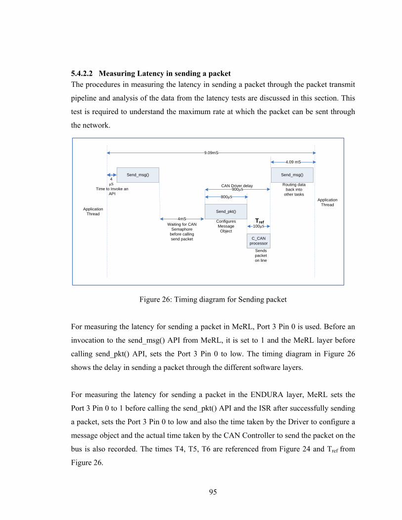
5.4.2.2 Measuring Latency in sending a packet The procedures in measuring the latency in sending a packet through the packet transmit
pipeline and analysis of the data from the latency tests are discussed in this section. This
test is required to understand the maximum rate at which the packet can be sent through
the network.
Send_msg()
Send_pkt()
4mS
100μS
C_CAN processor
Send_msg()
Waiting for CAN Semaphore
before calling send packet
800μS
900μSRouting data
back into other tasks
Configures Message
Object
Sends packet on line
CAN Driver delay4μS
Time to Invoke an API
Application Thread
Application Thread
9.09mS
4.09 mS
Tref
Figure 26: Timing diagram for Sending packet
For measuring the latency for sending a packet in MeRL, Port 3 Pin 0 is used. Before an
invocation to the send_msg() API from MeRL, it is set to 1 and the MeRL layer before
calling send_pkt() API, sets the Port 3 Pin 0 to low. The timing diagram in Figure 26
shows the delay in sending a packet through the different software layers.
For measuring the latency for sending a packet in the ENDURA layer, MeRL sets the
Port 3 Pin 0 to 1 before calling the send_pkt() API and the ISR after successfully sending
a packet, sets the Port 3 Pin 0 to low and also the time taken by the Driver to configure a
message object and the actual time taken by the CAN Controller to send the packet on the
bus is also recorded. The times T4, T5, T6 are referenced from Figure 24 and Tref from
Figure 26.
95

Time taken to send a packet through the ENDURA layer (T4) = 924 µSeconds
Time taken by MeRL to send a packet to ENDURA (T5) = 4.166 mSeconds
Time taken for sending a packet through the Application (T6) = 9.099 mSeconds
Time taken by the C_CAN Processor to send packet (Tref) = 110μSeconds
The total time taken for sending a packet is high, because the IDEAnix layer after
sending a packet reroutes the message id and payload back into a queue for other tasks
that might have registered for the same message id.
5.4.2.3 Bandwidth calculation for the CAN Application: The bandwidth that can be expected from the CAN application based on the Latency tests
performed in section 5.4.2.1 and 5.4.2.2 are calculated in this section. The entire CAN
application (IDEAnix + ENDURA) is taken into consideration for this measurement.
Total Time taken to process a packet = 856 μSeconds
The Max bandwidth for CAN = 1 Mbits/sec
= 1 Mbits/sec / 108 (app. packet size)
= 9260 packets/ sec
Time taken by the application to process 9260 packets:
Time taken = 9260 * 856 μSeconds
= 7.87 Seconds
Number of packets that can be received at 856 μSeconds:
Number of bits that can be received = (9260/ 7.87)* 108
= 1176 * 108
= 127074 Bits/ Sec
= 124 KBits/Sec ( appx)
The Maximum bandwidth that can be supported by the IDEAnix layer together
with ENDURA is 124 Kbits/ Sec. This value matches with the bandwidth result
96

where the maximum bandwidth obtained is 100 KBits/Sec.
5.4.2.4 The Bandwidth Calculation for ENDURA layer The bandwidth that can be expected from the ENDURA layer based on the Latency tests
performed in section 5.4.2.1 and 5.4.2.2 are calculated in this section. The ENDURA
layer alone is considered independent of IDEAnix for this Bandwidth measurement.
Total Time taken to process a packet in Driver = 100 μSeconds
The Max bandwidth for CAN = 1 Mbits/sec
= 1 Mbits/sec / 108 (app. packet size)
= 9260 packets/ sec
Time taken by the driver to process 9260 packets:
Time taken = 9260 * 100 μSeconds
= 0.926 Second ( < 1 second )
The Maximum bandwidth that can be supported by the ENDURA layer (without
including the IDEAnix and Operating system) is 1 MBits/ Sec. Hence the driver is
implementation is able to meet the functional requirement of supporting the maximum
expected bandwidth of 1 MBits/Sec.
5.4.3 Reliability testing The requirements for reliability testing and the test logic used in the reliability tests are
detailed in this section. The reliability of the application is a key property in analyzing the
performance characteristics of the network. Controller Area Network was subject to 40
hours of continuous packet forwarding and the packets of payload 8 bytes are sent
continuously at the maximum possible packet rate of 10ms/packet.
Table 6: Reliability test data after continuous run for 40 hours
Packet rate
( kbits/sec)
Number of
hours of test
Number of
packets sent
Number of packets
Received lost
10 40 14,406,543 14,406,543 0
97

After running the packets for 40 hours, it was found that no packet was lost in the process
and the packet counts on the transmitting and receiving pipeline were identical. No
leakages of buffers or unexpected software resets were observed. Based on the present
software environment and reliability test data, the CAN application was found to be
reliable at the bandwidth of 100KBits/ sec and received all the packets sent at that rate.
5.4.4 Sporadic Packet Tests This section provides an overview on the motivation behind the Sporadic packet testing
of the CAN network and the test setup, input and data analysis from the tests. CAN is an
event-based network and asynchronous events on the system triggers packet movement
on the network. Sporadic tests are used to test the robustness of the CAN application for
packet bursts that might occur on the network. Hence the application is tested with bursts
of packets at different rates and for random durations and the results of the sporadic tests
are shown in Table 7.
Table 7: Sporadic Test data for CAN
Sl.
No
Packet
rate
(Kbits
/sec)
Duration of
packet burst
(minutes)
Number of packets
sent
Number of packets
Received lost
1. 1000 5 300 300 0
2. 500 5 600 600 0
3. 100 10 6480 6480 0
4. 50 7 8980 8980 0
5. 10 2 15409 15409 0
Based on the sporadic packet burst test data, it can be deducted that the CAN network is
capable of receiving packets in bursts at different rates/packet numbers and no packets
are lost due to communication errors.
98

5.5 Performance Analysis Summary The summary of the result of the ENDURA layer implementation validation and the
efficiency/ feasibility of the network for a reconfigurable embedded system are discussed
in this part. The performance analysis data indicates the operating bandwidth where
maximum reliable operation from the CAN application can be expected from the system.
The conformance test for the ENDURA layer to the CAN protocol specification shows
that the ENDURA layer meets the requirements of the CAN protocol and can be
interfaced with other standard CAN hardware without any compatibility issues. The
implementation also provides the feature of translating packet types from CAN 2.0A to
CAN 2.0B and vice-versa. This can be very useful for the CAN UAV application where
the Auto-pilot sends the packet on CAN 2.0B format and the rest of the system desires
packets of CAN 2.0A type.
The Bandwidth tests for the CAN application measures the maximum capability of the
embedded network without loss of packets on the network and the CAN application
achieves maximum efficiency when the packets are transmitted at or greater than
10ms/packet rate and reliable communication is possible at 100KBits/sec based on this
data.
The latency tests for the CAN application validated the measurements of the bandwidth
tests and maximum time taken to send a packet as 9.09mSeconds and the time to receive
a packet as 900μSeconds. The calculations based on the latency measurements showed
the maximum bandwidth that can be supported by the CAN application together with
IDEAnix is 120Kbits/Sec. This bandwidth is approximately 1/10th of the peak value
expected and the drop in efficiency of the network layer due to the overhead added by the
operating system in sending a packet and the time taken by the CAN core to send a
packet through the network after a message object has been configured. As a stand-alone
module the ENDURA layer has a latency of 100μSeconds to receive a packet through the
network and is capable of receiving packets at 1Mbits/ Sec.
99

100
The performance data provides an insight on the maximum reliable bandwidth of the
CAN application and the performance data has to be considered during the system design
phase before deploying the CAN application. For the CAN UAV project, the maximum
packet frequency is 20Hz and this requires a minimum bandwidth of 50KBits/ Sec. As
the performance data extracted from the CAN application is capable of meeting the
desired bandwidth/latency requirements, the CAN application can reliably be ported for
CAN UAV project.

Chapter 6: Conclusion The design objectives were setup by the constraints and requirements mentioned in Chapter
1. The CAN protocol specification was analyzed in Chapter 2 and the specifications for the
ENDURA layer was set using the protocol capabilities. The various modules that were to
form the driver layer were identified and analyzed individually in Chapter 4. The individual
modules implementation details were discussed in detail and the fault-tolerant schemes that
can be added to module to meet the requirements of the reconfigurable architecture were
explained.
The ENDURA implementation was proved to work as per the functional requirements of the
network layer, with the performance and conformance test data. The performance and
conformance test data prove that the CAN application is capable of reliably communicating
with the nodes on the network at 120 KBits/Sec at variable payloads from 0-8 bytes. Based
on the performance data, the viability of the CAN application for an UAV type of application
was proven to operate reliably under the timing / bandwidth constraints. The ENDURA layer
uses no operating system calls in its implementation, making the driver layer independent
and portable across operating systems. The work on ENDURA layer presented here is a part
of a larger research on reconfigurable embedded architecture by the Intelligent Dependable
Embedded Architecture (IDEA) lab at University of Kentucky. The implementation and
subsequent validation of the ENDURA layer aids in the design of dynamically reconfigurable
architectures.
There are several enhancements and future research directions for this thesis work. The
CAN application as per the present implementation is capable of operating at a bandwidth of
120KBits/Sec. The maximum bandwidth supported by the application can be improved
significantly if the tick time on the MicroC OS-II can be decreased from its present 10ms/
tick timing. The OS tick can be decreased by reducing the Timer 0 counter reload value on
the C8051F040 board and increasing the number of ticks per second to more than 100 ticks
per second. It is to be noted that the OS kernel will also have to be modified and validated
accordingly to match the timing requirements. An another improvement would be to increase
101

102
the clock rate to make the C8051F040 board run the programs faster and improve upon the
speed of the CAN communication.
The MeRL send packet module can be optimized by reducing the time taken to route a packet
within the tasks on a same processor. This can be improved by allowing the user task to
register for a packet with the driver and as the receive packet pipeline is at least 10 times
faster than the time taken by the MeRL to route a packet internally to other tasks, this would
improve the send packet pipeline time by a factor of 10.
The scope of Controller Area Network can be extended by adding CAN Gateways that are
capable of communicating with other networks of different physical media. The CAN
gateways can convert the packets of CAN type into any other broadcast network packets and
thereby be able to communicate with other networks that are different from CAN. For
example in UAV application, 2 UAVs with different physical networks (CAN and a wireless
network like 802.15.4) can interact with each other through a Gateway that is capable of
converting a CAN packet into 802.15.4 packets and vice-versa. This can be used in forming
Ad-hoc networks dynamically in forming joint missions.

Appendix A: CAN Protocol Specification
Physical layers for CAN Standard:
This section provides details on the different CAN physical layer standards that are available
in the market and their properties, electrical signals and the peak bandwidth supported.
1. CAN Standard ISO-11898-2 This is also called the “High Speed CAN” and the 11898-2 implementation supports
bandwidth up to 1 Mbits/Sec for a maximum distance of 40m and is a two wired balanced
signaling scheme. The characteristic line impedance for the bus is specified to be at 120Ω
and for the two wire system, the common mode voltage ranges are from -2V for CAN_L to
+7V for CAN_H lines. The number of nodes that can be connected to the network is limited
by the Electrical busload. For the Peak 1Mbits/sec bandwidth to be achieved the maximum
propagation delay can be 5ns/m. The CAN standard 2.0A/B specifies that for all the nodes to
communicate within the network, all the nodes must use the similar bit-timing calculation
[5].
2. CAN Standard ISO-11898-3 This is also called the “Low-Speed CAN” or “Fault-Tolerant” CAN and the 11898-3
implementation supports bandwidth up to 125 Kbits/sec. Even though this standard is a two-
wired balanced signaling, the bus could support asymmetric signaling even if one of the
wires is grounded or damaged. As per the CAN 2.0A/B Specification, the 11898-3 standard
is assumed to be for shorter network and the maximum length supported depends on the
maximum load expected on the network. The physical layer can support up to a maximum of
32 nodes. The common mode voltage specification is from -2V to +7V and the power supply
is defined at +5V.
3. SAE J2411 Single wire standard SAE J2411 is also a CAN standard for the physical layer with low requirements on the bit
rate, bandwidth, bus length. The maximum number of nodes that can be present on the
network is restricted to 32 and SAE J2411 uses an unshielded single wire for communication
at maximum of 33 Kbits/sec.
103

4. Time Triggered CAN (TTCAN): ISO-11898-4 CAN2.0A/ B implementations are event-driven networks i.e asynchronous events trigger
movement of packets on the network. But in many automotive/ space applications,
guaranteed bus access for higher priority packets at a certain rate is required besides
supporting asynchronous behavior. Hence TTCAN protocol was standardized to support
deterministic communication on top of CAN.
TTCAN protocol requires a global clock that has to be implemented in hardware and all the
other modifications are software extensions to existing BasicCAN. All the nodes wait for a
global reference message which is sent periodically from a central reference node and all the
nodes register to get bus access in multiples of reference message slots. The nodes can send a
packet on the bus only when the required message slot time has been reached and by this
mechanism, both TTCAN and BasicCAN nodes can exist/ communicate on the same bus.
Bit-timing for CAN Physical layer (PHY)
This section provides more details on the bit-timing segments within a CAN bit-time and the
parameters that are involved in adjusting the sampling point.
1. Synchronization segment (SYNC_SEG)
2. Propagation delay segment (PROP_SEG)
3. Phase buffer segment 1 (PHASE_1)
4. Phase buffer segment 2 (PHASE_2)
Sample point is defined by the CAN 2.0A/B as the time at which the signal level on the bus
is read and interpreted as either “Recessive (5V)” or “Dominant (0V)”.
1. Synchronization segment (SYNC_SEG): The synchronization of the bit-timing between the nodes occurs during this segment and the
transition of Recessive (1) to Dominant (0) or vice-versa should occur within this bit-time.
2. Propagation delay segment (PROP_SEG): The propagation delay segment is for the countering the physical delay in the electrical
signals reaching the nodes and it is at least 2 times the time taken by the electrical signals on
104
the bus sent between the edge nodes on the network. Propagation delay also includes the
input comparator delay at the receiver and also the transmitter driver relay delay.
PROP_SEG = (2* Signal delay on bus b/w end nodes) +
Comparator delay at receiver + Driver delay at transmitter
3. Phase Buffer Segments 1 and 2: CAN uses synchronized transmission at the bit-level and frame-wise synchronization cannot
be applied since there is only one Start of Frame (SOF) bit in every frame. Hence continuous
resynchronization is required by the nodes to enable receivers decode the packets correctly
and phase buffer segments are included to compensate for the edge phase errors. Phase buffer
segments can be lengthened or shortened with resynchronization. There are two types of
synchronization in the physical layer during data transmission.
a. Hard Synchronization: Hard synchronization occurs during the start of every frame transmission and at the end of
the SYNC_SEG, the bit-timing registers are restarted so that the edge that caused the Hard
Synchronization lies within the SYNC_SEG.
b. Resynchronization: Resynchronization occurs within the frame and it is used to shorten or lengthen the Phase
buffer segments so that the sampling point lies within the detected edge.
Fault Confinement Since CAN deviates from the conventional arbitration mechanisms, it is a possibility that one
faulty node could block the entire system from operating normally if left unchecked. This
section explains mechanisms to isolate a faulty node(s) and limit the effect of such a scenario
where a faulty node disrupts communications.
The mechanism of error signaling could enable a faulty node to generate error flags
continuously and could effectively block the transmission of normal frames on the network.
This scenario is analogous to “ICMP Error messages attack” on the TCP/IP based inter-
network, where an ICMP Error messages could be continuously sent on the network to
swamp the nodes from transmitting useful data.
105

To facilitate the confinement of errors, the CAN 2.0A/B protocol specifies that each node
should contain two counters.
1. Transmit counter
2. Receive Error counter
The Receive Error counter is increased by a fixed value whenever the node detects an
erroneous packet on the network. The value of the counter is decreased by a specific fixed
value whenever a packet is received correctly. To ensure correct functional working of this
mechanism, the counter value is increased by larger number than the decrement value.
The Transmit counter is used to record errors encountered during or immediately after the
transmission of packet on the network. If a transmitting node detects an error in transmission,
it increases the counter value by a different fixed value and decreases it by 1 whenever it
successfully sends a packet on the network.
The values of the counters are used to determine the state of the node and are critical in fault
confinement logic implementation. The value by which the counter values are increased
varies depending upon the scenario in which the error was encountered.
The fault confinement state machine could be in any of the 3 states:
1. Error Active
2. Error Passive
3. Bus Off
‘Error Active’ state is the observed by nodes who have Transmit and Receive error counter
values less than 128. The value of less than 128 signifies that the node in itself is free from
faults and detects the errors on the bus reliably. Only the ‘Error Active’ nodes are allowed to
transmit Active Error flags (6 Dominant Bits) during the Error signaling.
‘Error Passive’ state is observed by nodes who have Transmit or Receive error counter values
greater or equal to 128. Since the error increment and decrement values are different, a value
greater than 128 signifies that there could be a fault in the node. ‘Error Passive’ nodes could
only transmit Passive Error flags (6 Recessive Bits) during error signaling. ‘Error Passive’
106

nodes take part in error signaling, but as long as the same error is not recognized by any other
‘Error Active’ node, the Passive Error flags will be ignored. An ‘Error Passive’ node is
allowed to become ‘Error Active’ only after its Transmit and Receive error counter values
are less than 128.
‘Bus Off’ state is observed when the Transmit error counter value exceeds 256 and used to
isolate a node or nodes from communicating on the network. A node can switch from ‘Bus
Off’ to ‘Active Error’ when it correctly recognizes 128 occurrences of 11 consecutive
Recessive bits. The Transmit and Receive error counters are reset to 0 and Active Error flags
rights are enabled.
These mechanisms ensure that decisions on fault confinement, isolation of faulty nodes and
rejoining the network are distributed to individual nodes and effectively ensure fault
tolerance of the network under erroneous conditions.
CAN Transfer Layer This section provides an overview of the CAN transfer layer and the functionalities of the
module and the CAN Transfer Layer represents the kernel of the CAN protocol. The Transfer
layer is responsible for the actual frame communication in the CAN bus and the CAN
specification defines the standard for CAN Transfer layer precisely. For an implementation
of CAN to be compatible with other implementations, the Transfer Layer should adhere to
the CAN 2.0 A/ B specification strictly.
The CAN Transfer layer is responsible for the Transport protocol and the functionalities of
the transfer layer includes Arbitration of the CAN bus, Frame control and formation, Data
Transmission / Reception on the Can Bus, Error identification/ Signaling, Fault confinement,
Remote transmit request and Packet Acknowledgement.
The transfer layer processes the message to be sent from the Object layer and formats the
message into the CAN frame and transmits it on the CAN Bus and also receives the CAN
frame, checks for errors and passes the message onto the Object layer. The transfer layer also
107

108
controls general configurations related to the bit-timing on the CAN bus and also arbitration
of the bus (identifying if the bus is idle or some other node is transmitting).
The Transfer layer implementation is handled by the CAN Controller chips and offer limited
flexibility in implementation and also the configuration of the transfer layer is performed
through the initial configuration of the CAN Controller Engine.

Appendix B: C_CAN Processor
C_CAN Modes of Operation: The C_CAN controller supports different modes of operation to facilitate debugging and
analysis of the network. The test modes in which the C_CAN controller can be operated are
1. Basic Mode
2. Loop-back mode
3. Silent mode
4. Loop-back & silent mode
For testing the network with any of these modes, the Test mode has to be enabled in the CAN
Control register [20]. When the 7th bit is set in the CAN Control Register (Address 0x00 and
0x01), the test mode register is enabled and this allows the software to test the network under
different modes listed.
Figure 27: Test Register Details
Table 8: Test Register Bits
Bit No Symbol Description
0-1 R Reserved
2 BSC Basic Mode
3 S Silent Mode
4 LB Loop back Mode
5-6 TX0, TX1 Transmit Control
7 RX 0 – CAN_RX pin is Dominant
1 – CAN_RX pin is Recessive
8-15 R Reserved
109

1. Basic Mode: When the CAN Control Register is in Test Mode and the 2nd Bit of the Test Register
is set, Basic mode is enabled. In Basic mode, Interface Register 1 is used as Transmit buffer
and Interface Register 2 is set for Receive buffer. All Message control registers are disabled
and once the bus is idle, the value from the Interface Register 1 is loaded on the CAN TX
shift register and transmitted on the network. When a packet is received from the network,
the message is stored on Interface Register 2 without any acceptance filtering. This mode is
used for testing the basic transmission and reception capabilities of the CAN controller.
2. Loop-Back mode: The Loop-back mode is used to test the Transmit and Receive functionality of the
driver by treating the packet sent through the CAN_TX as a packet received. Acknowledge
errors are ignored in this mode. The CAN_RX pin is kept at Recessive level, so no external
packets can be received. Loop-Back mode can be enabled by setting the 4th bit of the Test
Register.
3. Silent Mode: In Silent mode, the CAN controller receives all the packets that are found on the
network but the CAN_TX pin is set at Recessive level. This enables successful reception of
all the packets on the network, including remote request frames, but no packet data is sent out
through the bus. This mode can be used to analyze the network without affecting the
communication on the bus.
4. Loop-Back and Silent Mode Loop-back and Silent mode can be combined together by setting the bits 3 and 4 of
the Test register. This mode of testing is called ‘Hot Self-test’ [20] where the CAN network
driver can be tested without sending any information to the CAN transceiver connected to the
CAN_RX and CAN_TX pins. The CAN_RX pin is disconnected from the CAN core and the
CAN_TX pin is held at Recessive level.
110

Registers in C_CAN processor:
Protocol Registers in C_CAN processor: Table 9: List of Protocol Registers in C_CAN processor
Sl.
No
Protocol Register Description
1 CAN Control Register Controls the Global enable/ disable scheme for
the error, interrupts, change configuration and
Test registers
2 CAN Status Register Indicates the status of Tx/Rx, error active/passive,
Warning and bus off information
3 CAN Error Counter
Register
This is a read-only register and gives the counts
of the number of transmit or receive errors on the
bus
4 Bit Timing Register This register is used to configure the Bit timing
for the CAN controller (as per the CAN
bandwidth required).
5 Test Register This register is used for testing the CAN protocol
with different modes such a Loop back, Silent,
Silent & Loop back and Basic CAN mode
6 BRP Extension Register This register is used to pre-scale the baud rate for
the CAN communication
111

Interface Registers in C_CAN processor: Table 10: List of Interface Registers in C_CAN processor
Sl.
No
Message Interface
Register
Description
1 IF Command Request This register is used to read or write into a message
object. Once a message object number is written
into this register, an automatic transfer to or from
the message object will be started.
2 IF Command Mask
Register
The mask register is used to specify the direction of
movement of data and to specify which message
RAM as source or target
3 IF Mask Registers Interface Mask registers are used to specify the
mask that will be used for message arbitration if
enabled in the Command mask register
4 IF Arbitration Registers Interface arbitration registers is used to specify the
message identifier to apply the interface mask
5 IF Message control
registers
Interface message control registers contain the data
related to message object configuration
6 IF Data Registers A1 &
A2 and B1 and B2
Interface Data registers 1 &2 buffer the data for the
before storing in the Message RAM or transmitting
on the CAN bus. The CAN data is stored in Little
Endian format with the LSB occupying the lower
address and the MSB occupying the higher address.
But the bytes are transmitted in Network byte order
(Big Endian).
112

Message handler Registers in C_CAN processor: Table 11: List of Message handler Registers in C_CAN processor
Msg handler
Reg
Description
Interrupt
Register
The interrupt register indicates which of the message objects
currently have an interrupt pending. If more than one message
object has an interrupt pending, the interrupt register only
contains the message object number of highest pending interrupt.
The flag remains in active until the interrupt is serviced
Transmission
Request
Registers
Transmission request register indicates which of the message
objects currently have a request to send a message on to the bus.
This register provides the transmit request status by reading the
TxRqst bit from all the 32 message objects.
New Data
Registers
The new data registers are compliment of Transmit request
registers and provide which of the message object has newly
received packet data after it was last cleared by the CAN core.
The new data registers and Transmission request registers are
both 4 bytes in length and each bit represent one of the 32
message objects.
Interrupt
Pending
Register
Interrupt pending register indicates which of the message object
currently has a pending interrupt that is yet to be serviced. The
values for the interrupt pending registers are obtained by reading
the IntPnd bits of the 32 message objects. Lower the message
object number, higher the priority associated with it and this
priority determines which of the message object interrupt is
updated on the Interrupt register for servicing.
Message
Valid
Register
The message valid registers contain the value of the MsgVal bit
of the 32 message objects. The MsgVal bits indicate which
among the 32 message objects have been configured for either
transmit or receive.
113

References [1] O. Rawashdeh and J. Lumpp, Jr. “Run-Time Behavior of Ardea: A Dynamically
Reconfiguring Distributed Embedded Control Architecture.” IEEEAC paper #1516. IEEE
Aerospace Conference. Big Sky, Montana. March 2006.
[2] T. Arrowsmith, D. Brown and Dr. J. E. Lumpp Jr, "Reconfigurable Embedded Control
for UAVs”, 12th Annual Kentucky EPSCOR Conference. Louisville, KY.
May 2006.
[3] Association for Unmanned Aerial Vehicle Systems International. 2700 S. Quincy
Street, Suite 400, Arlington, VA 22206, http://www.auvsi.org, September 7th, 2007.
[4] D. Brown, C. Collins, D. McClure, A. A. Meriden,P. Profitt, M. Smith, and V.
Yadack, “University of Kentucky Aerial Robotics Team: 2006 AUVSI Student UAV
Competition Design”, University of Kentucky, Lexington, KY 40506, Spring 2006.
[5] CAN in Automation. Am Weichselgarten 26, DE-91058 Erlangen, http://www. can-
cia.org, September 7, 2007.
[6] CAN Specification version 2.0, Part A. Robert Bosch GmbH, Stuttgart, Germany,
1991.
[7] CAN Specification version 2.0, Part B, Robert Bosch GmbH, Stuttgart, Germany, 1991. [8] KVaser Incorporated. 567 W Channel Island Blvd #336, Port Hueneme, CA 93041,
http://www.kvaser.com, September 7, 2007.
[9] K. H. Johansson, M. Torngren, L. Nielsen, “Vehicle Applications of
Controller Area Network”, Handbook of Networked and Embedded Control Systems,
Birkhäuser, 2005. Invited paper.
[10] Light Electric Vehicle Conference Presentation, Hsinchu Taiwan, March 2007.
114
[11] National Institute of Marine Research, 155, rue Jean-Jacques Rousseau
92138 Issy-les-Moulineaux Cedex, http://ifremer.fr/, May 9, 2007.
[12] Michael Stock Flight Systems, 27a Umsatzsteuergesetz: DE151230778,
http://www.canaerospace.com, September 7, 2007.
[13] Infineon C500 Architectures and Instruction Set Manual, Infineon Technologies,
http://www.infineon.com/cms/en/product/channel.html?channel=ff80808112ab681d0112ab6
b76fa0841, July 2000.
[14] Infineon XC866 Product Brief, Infineon Technologies, http://www.infineon.com
/cms/en/product/channel.html?channel=ff80808112ab681d0112ab6b81d00865, February 7,
2007.
[15] Infineon C161CS Data sheet 3.0v, Infineon Technologies, http://www.infineon.
com/cms/en/product/channel.html?channel=ff80808112ab681d0112ab6b38840779&tab =2,
Jan 01, 2001.
[16] Infineon XC2200 Family Product Brief, Infineon Technologies,
http://www.infineon.com/cms/en/product/channel.html?channel=ff80808112ab681d0112ab6
b655c0807, March 7, 2007.
[17] Silicon Laboratories C8051F04x data sheet, Silicon Laboratories, http://www.
silabs.com/public/documents/tpub_doc/dsheet/Microcontrollers/CAN/en/C8051F04x.pdf,
December, 2005.
[18] FlexRay Consortium, http://flexray.com, September 9, 2007.
[19] Texas Instruments TMS470R1x data sheet, Texas Instruments, http://focus.ti.com
/mcu/docs/mcusupporttechdocsc.tsp?sectionId=96&tabId=1502&abstractName=spnu197e,
July 2005.
115

[20] C_CAN User Manual Revision 1.2, Robert Bosch GmbH, http://www.
semiconductors.bosch.de/en/20/can/products/ccan.asp/, June 6, 2000.
[21] PAXCAN protocol, Intelligent Dependable Embedded Architecture Lab, University
of Kentucky, http://www.engr.uky.edu/idea/wiki/doku.php?id =projects:
active:pax:workspace:protocol , September 9, 2007.
[22] Weisstein, Eric W. "BCH Code.", From MathWorld--A Wolfram Web Resource.
http://mathworld.wolfram.com/BCHCode.html, October 17, 2005.
[23] Dr. K Etschberger, “Controller Area Network”, Published by IXXAT Automation
GmbH, 88250 Weingarten, Germany, July 2001.
[24] Controller Area Network Solutions (M) Sdn Bhd, 34-2, Jalan Puteri 2/2, Bandar
Puteri Puchong, 47100 Puchong, Malaysia, http://www.cans.com.my, September 7, 2007.
[25] A. Avizienis, J.-C. Laprie and B. Randell, Fundamental Concepts of Dependability,
Research Report N01145, LAAS-CNRS, April 2001.
[26] RFC 124, Defense Advanced Research Projects Agency, Information Processing
Techniques Office, 1400 Wilson Boulevard, Arlington, Virginia, December 1979.
[27] RFC 2581, Defense Advanced Research Projects Agency, Information Processing
Techniques Office, 1400 Wilson Boulevard, Arlington, Virginia, December 1979.
[28] ISO/IEC 7498 The Basic Model, part 1, International Standard Organization,
http://www.sigcomm.org/standards/iso_stds/OSI_MODEL/index.html, 1994.
[29] Digital Equipment Corporation, Intel Corporation, and Xerox Corporation: "The
Ethernet -- A Local Area Network: Data Link Layer and Physical Layer (Version 2.0)",
November 1982.
[30] Bluetooth Special Interest Group (SIG), Bellevue, Washington, USA,
http://www.bluetooth.com/bluetooth/, September 18, 2007.
116

117
[31] Universal Serial Bus Implementers Forum, 5440 SW Westgate Dr., Portland, OR
94221, http://usb.org, September 18, 2007.
[32] IEEE 1394 Trade Association, 1560 East Southlake Blvd., Suite 242
Southlake, TX 76092, USA, http://www.1394ta.org/index.html, September 18, 2007.
[33] IEEE 802.15 TG4 Group, 11 Louis Road, Attleboro, MA 02703 USA, http://ieee802.org
/15/index.html, October 17, 2007.
[34] Freescale Semiconductors, 7700 West Parmer Lane, Austin, Texas 78729, USA,
http://www.freescale.com/webapp/sps/site/homepage.jsp?nodeId=01J4Fs2565, October 17,
2007.

Vita The author, Nithyananda Siva Jeganathan, was born in Palani, Tamil Nadu, India on January
9, 1982. He completed his undergraduate degree in Electronics and Communication
Engineering in April, 2003 from the University of Madras, Tamil Nadu, India. He joined the
Masters of Science program in Electrical Engineering at University of Kentucky in Fall 2005.
He was a Graduate Student Assistant at the Intelligent Dependable Embedded Architecture
(IDEA) lab at the Department of Electrical and Computer Engineering in UK.
118


