
B Precision Ground Plates and Flat Bars
C Lifting and Clamping Devices
D Guide Elements
E Ground Precision Components
F Springs
G Elastomer-Bars, -Sheets, -Sections
H FIBRO Chemical Tooling Aids
J Peripheral Equipment
K Cam Units
L Standard Parts for Mould Making
A Die Sets

subject to alterationsL2
Standard Parts for Mould Making

subject to alterations L3
Guide ElementsLocating units, roundLocating units, flat L6Compensation Discs L7Adjusting washers L7Ejector rods L8Centering sleeves L9Guide pillars L10-L11Guide pillars, shouldered L12-L15Locating guide pillars, shouldered L16-L19Guide pillars with flange L20Guide pillars (diagonal load pillars) L21Guide sleeves L22Guide bushes L23Locating guide bushes L24Ball Bearing Guides L25Oilless Guide Bushes with collar, Bronze with Non-Liquid Lubricant
L26-L29
Oilless Guide bushes Bronze with and without Non-Liquid lubricant
L30-L31
Rectangular Guides L32Rectangular Guides with rollers L33
Forming / DemouldingSliders for transverse bolt guides L36Bolt Guides L37Hardened Ejector Pins - DIN ISO 6751 L38Hotwork Precision Ejector Pins - Nitrided DIN ISO 6751
L39
Hardened Ejector Pins DIN ISO 8694 L40Hotwork Precision Ejector PinsNitrided DIN ISO 8694
L41
Hardened Ejector Pins - Conical Head similar to DIN 1530 Shape D
L42
Hotwork Precision Ejector Pins Nitrided - similar to DIN 1530 Shape D
L43
Blade Precision Ejectors -Hardened similar to DIN ISO 8693
L44
Hotwork Blade Precision Ejectors - Nitrided similar to DIN ISO 8693
L45
Precision-Ejector Sleeves - Hardened - DIN ISO 8405
L46
Hotwork Precision Ejector Sleeves - Nitrided - DIN ISO 8405
L47
Date insert, complete –(standard version)embossed lettering
L48
Date insert, complete –(short version)embossed lettering
L49
Quill holders for core tempering L50O-Rings L51
Gas SpringsFML Gas Springs for Mould Making L53-L69
Contents

subject to alterationsL4
subject to alterations L5
Guide Elements
subject to alterationsL6
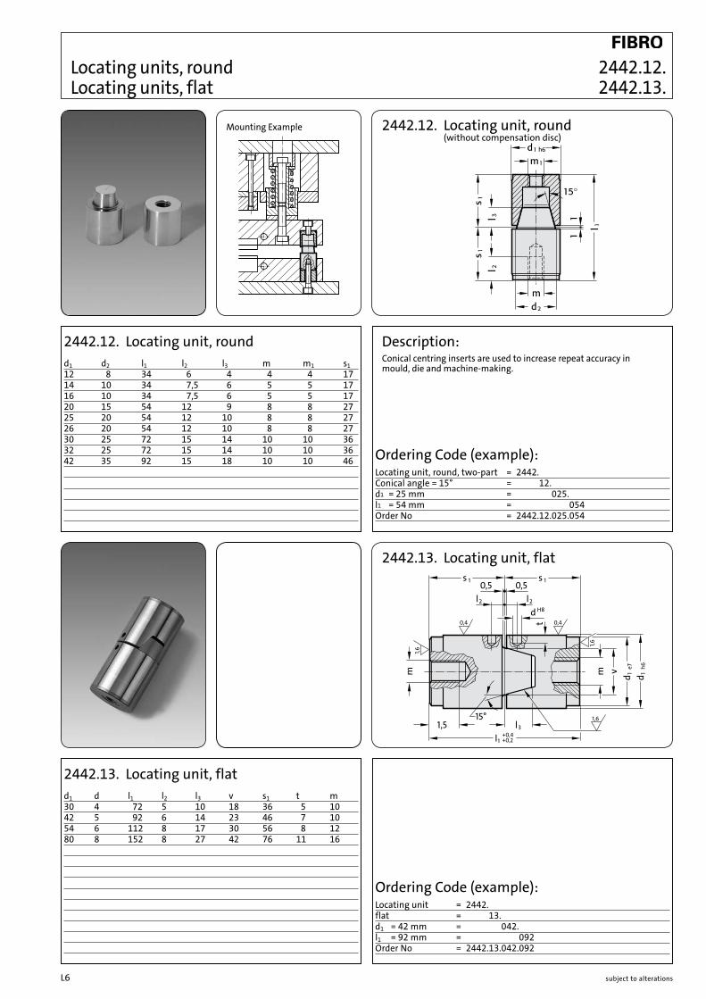
2442.12. Locating unit, round (without compensation disc)
Mounting Example
Locating units, round Locating units, flat
d1 d2 l1 l2 l3 m m1 s112 8 34 6 4 4 4 1714 10 34 7,5 6 5 5 1716 10 34 7,5 6 5 5 1720 15 54 12 9 8 8 2725 20 54 12 10 8 8 2726 20 54 12 10 8 8 2730 25 72 15 14 10 10 3632 25 72 15 14 10 10 3642 35 92 15 18 10 10 46
2442.12. Locating unit, round Description:Conical centring inserts are used to increase repeat accuracy in mould, die and machine-making.
Ordering Code (example):Locating unit, round, two-part = 2442.Conical angle = 15° = 2442.12.d1 = 25 mm = 2442.12.025.l1 = 54 mm = 2442.12.025.054Order No = 2442.12.025.054
v
l 31,5l +0,4
+0,21
1s1s0,50,5
2l2ld H8
e71d
h61dmm
t 0,40,4
1,6
1,6
1,615°
2442.13. Locating unit, flat
d1 d l1 l2 l3 v s1 t m30 4 72 5 10 18 36 5 1042 5 92 6 14 23 46 7 1054 6 112 8 17 30 56 8 1280 8 152 8 27 42 76 11 16
2442.13. Locating unit, flat
Ordering Code (example):Locating unit = 2442.flat = 2442.13.d1 = 42 mm = 2442.13.042.l1 = 92 mm = 2442.13.042.092Order No = 2442.13.042.092
2442.12. 2442.13.

subject to alterations L7
2442.12.3. 2442.12.4.
1,6
1,6
d ±0,12
d -0,2-0,44
d3
h+0
,2+0
,1 k±0
,1
2442.12.3. Compensation Discs
d1 s d d1 s d d1 s d d1 s d12 10 4,5 20 9 8,5 26 9 8,5 42 10 10,5 10 10 20 15 20 3014 5 5,5 20 30 10 30 30 10 12,5 14 40 20 19 25 9 10,5 3016 5 6,5 10 40 10 15 50 15 20 32 10 12,5 19 25 20 20 35 30 25 45 40 55 50
2442.12.3. Compensation Discs
Ordering Code (example):Locating unit, round = 2442.12.Compensation Disc = 2442.12.3.d1 = 25 mm = 2442.12.3.025.s = 10 mm = 2442.12.3.025.010Order No = 2442.12.3.025.010
2442.12.4. Adjusting washers
d4 d3 d2 h k14 5,5 16 5 3,220 8,5 25,5 9 6,326 8,5 31,5 9 6,330 11 35,5 10 6,342 11 47,5 10 6,3
2442.12.4. Adjusting washers
Ordering Code (example):Locating unit, round = 2442.12.Adjusting washer = 2442.12.4.d4 = 30 mm = 2442.12.4.030Order No = 2442.12.4.030
Compensation Discs Adjusting washers

subject to alterationsL8
l 2 l 4
d 2d 2g6
1d
l js12
R Z4
SW
d1 l d2 l2 l4 A/F24 120 M12 25 14 19 140 160 180 200 24030 180 M16 30 16 24 220 260 300
3300.10. Ejector rodsd1 l d2 l2 l4 A/F10 60 M 6 16 9 9 70 80 100 120 14014 60 M 8 16 11 12 70 80 100 120 140 160 18018 100 M10 20 12 14 120 140 160 180 200 220 24020 100 M12 25 14 16 120 140 160 180 200 220 240
Ejector rods
3300.10. Ejector rods
Ordering Code (example):Ejector rod = 3300.10.d1 = 20 mm = 3300.10.020.l = 140 mm = 3300.10.020.140Order No = 3300.10.020.140
3300.10.
A/F

subject to alterations L9
+0,5
l2
l1
l ±0,5
k63d
j63d1d
2d
R Z4
3100.04.
3100.04. Centering sleeves
d3 l d2 d1 l1 l254 60 M20 43 13 4,5 80 120 160 200 240 280
3100.04. Centering sleevesd3 l d2 d1 l1 l214 20 M 6 11 8 2 30 40 50 60 70 80 10020 30 M 8 16 13 2 40 60 80 100 120 140 16026 30 M10 21 13 2,5 40 60 80 100 120 140 160 18030 40 M12 25 13 2,5 60 80 100 120 140 160 180 200 24042 40 M16 33 13 4,5 60 80 100 120 140 160 180 200 220 260 300
Ordering Code (example):Centering sleeve = 3100.04.d3 = 26 mm = 3100.04.026.l = 30 mm = 3100.04.026.030Order No = 3100.04.026.030
Centering sleeves

subject to alterationsL10
l1
l
0,4x45°
k ±0,05
-0,2
4d
h41d
8°
R2
Guide pillars
3202.12. Guide pillars
d1 l d4 k l112 80 16 4 4 100 12018 120 22 6 7 140 16030 160 36 6 7 200 240
3202.12. Guide pillars
Ordering Code (example):Guide pillar = 3202.13.d1 = 18 mm = 3202.13.018.l = 160 mm = 3202.13.018.160Order No = 3202.13.018.160
Ordering Code (example):Guide pillar = 3202.12.d1 = 18 mm = 3202.12.018.l = 160 mm = 3202.12.018.160Order No = 3202.12.018.160
l1
l
h41d
8°
R23
8°
3202.13. Guide pillars
d1 l l112 100 3 12518 125 6 16030 160 6 240
3202.13. Guide pillars
3202.12. 3202.13.
subject to alterations L11
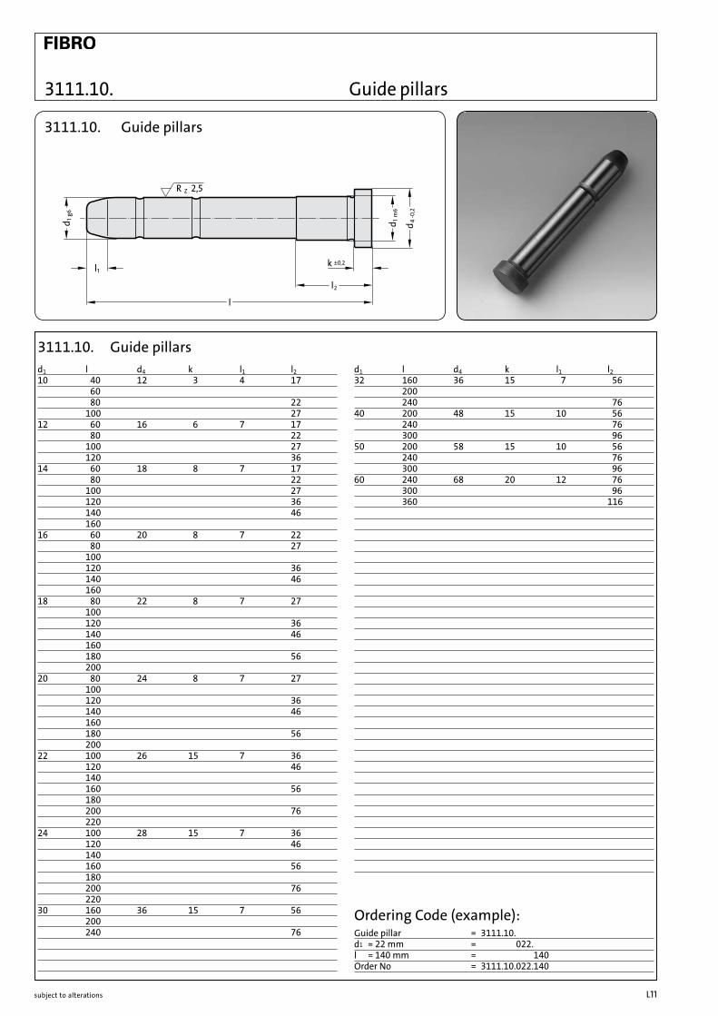
3111.10.
R Z 2,5
l
l1
l2
k ±0,2
-0,2
4d
m6
1d
g61d
3111.10. Guide pillars
d1 l d4 k l1 l232 160 36 15 7 56 200 240 7640 200 48 15 10 56 240 76 300 9650 200 58 15 10 56 240 76 300 9660 240 68 20 12 76 300 96 360 116
d1 l d4 k l1 l210 40 12 3 4 17 60 80 22 100 2712 60 16 6 7 17 80 22 100 27 120 3614 60 18 8 7 17 80 22 100 27 120 36 140 46 160 16 60 20 8 7 22 80 27 100 120 36 140 46 160 18 80 22 8 7 27 100 120 36 140 46 160 180 56 200 20 80 24 8 7 27 100 120 36 140 46 160 180 56 200 22 100 26 15 7 36 120 46 140 160 56 180 200 76 220 24 100 28 15 7 36 120 46 140 160 56 180 200 76 220 30 160 36 15 7 56 200 240 76
3111.10. Guide pillars
Ordering Code (example):Guide pillar = 3111.10.d1 = 22 mm = 3111.10.022.l = 140 mm = 3111.10.022.140Order No = 3111.10.022.140
Guide pillars

subject to alterationsL12
Guide pillars, shouldered
A 0,80,8
-0,2
4d
k63
d
e73
d
g61d
∅0,01 A
k ±0,05
s -0,5-1,0
l1
l
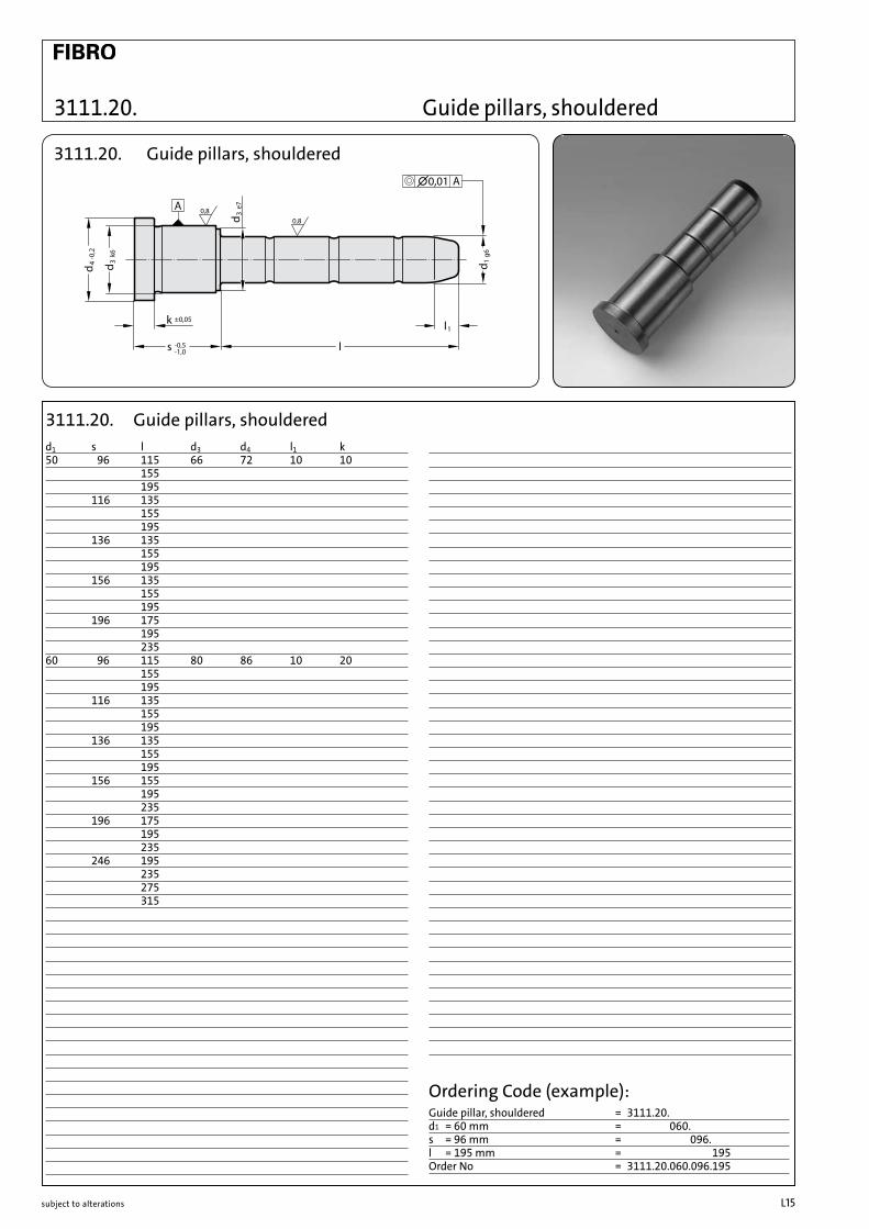
3111.20. Guide pillars, shouldered
d1 s l d3 d4 l1 k14/15 56 20 20 25 7 6 35 55 75 95 66 55 65 95 76 55 95 86 55 95 18/20 22 20 26 31 7 6 35 40 45 50 55 60 65 70 80 85 115 27 20 35 40 45 50 55 60 65 70 80 85 105 125
d1 s l d3 d4 l1 k9/10 12 45 14 16 4 3 17 20 30 35 22 25 35 55 27 25 30 35 50 36 25 35 45 46 30 45 55 75 14/15 22 20 20 25 7 6 35 40 45 50 55 65 70 90 110 27 20 35 40 45 55 65 85 105 36 20 35 40 45 55 65 75 95 46 20 35 45 65 85 105
3111.20. Guide pillars, shouldered
Ordering Code (example):Guide pillar, shouldered = 3111.20.d1 = 14 mm = 3111.20.014.s = 36 mm = 3111.20.014.036.l = 75 mm = 3111.20.014.036.075Order No = 3111.20.014.036.075
3111.20.

subject to alterations L13
3111.20.
A 0,80,8
-0,2
4d
k63
d
e73
d
g61d
∅0,01 A
k ±0,05
s -0,5-1,0
l1
l
3111.20. Guide pillars, shouldered
d1 s l d3 d4 l1 k22/24 36 25 30 35 7 6 45 50 55 60 70 75 80 95 115 135 165 46 25 45 50 60 65 70 80 85 105 125 165 56 25 45 55 75 95 115 165 66 55 75 95 76 25 45 55 75 95 115
d1 s l d3 d4 l1 k 18/20 36 20 26 31 7 3 35 40 45 50 55 60 65 70 75 80 95 115 135 46 20 45 65 85 105 135 165 56 20 26 31 7 6 35 55 75 95 66 55 75 95 76 55 75 95 86 55 75 95 96 55 95 116 115 22/24 27 25 30 35 7 6 45 50 60 65 70 80 85 105 125 165
3111.20. Guide pillars, shouldered
Ordering Code (example):Guide pillar, shouldered = 3111.20.d1 = 24 mm = 3111.20.024.s = 76 mm = 3111.20.024.076.l = 115 mm = 3111.20.024.076.115Order No = 3111.20.024.076.115
Guide pillars, shouldered

subject to alterationsL14
Guide pillars, shouldered
A 0,80,8
-0,2
4d
k63
d
e73
d
g61d
∅0,01 A
k ±0,05
s -0,5-1,0
l1
l
3111.20. Guide pillars, shouldered
d1 s l d3 d4 l1 k30/32 116 75 42 47 7 6 115 155 136 95 115 155 156 115 155 196 155 195 40/42 56 75 54 60 7 10 115 155 195 66 75 135 76 75 115 175 86 75 135 96 75 115 155 116 95 135 195 136 95 135 215 156 115 155 215 196 155 195 235
d1 s l d3 d4 l1 k22/24 86 55 30 35 7 6 75 95 96 55 75 95 116 75 115 155 136 135 30/32 27 45 42 47 7 6 65 105 165 36 55 75 95 115 155 46 45 65 85 105 125 165 56 55 75 95 115 135 175 66 55 75 95 115 135 175 76 55 75 95 115 155 86 55 75 95 115 155 96 55 75 95 115 155
3111.20. Guide pillars, shouldered
Ordering Code (example):Guide pillar, shouldered = 3111.20.d1 = 32 mm = 3111.20.032.s = 116 mm = 3111.20.032.116.l = 115 mma = 3111.20.032.116.115Order No = 3111.20.032.116.115
3111.20.
subject to alterations L15
3111.20.
A 0,80,8
-0,2
4d
k63
d
e73
d
g61d
∅0,01 A
k ±0,05
s -0,5-1,0
l1
l
3111.20. Guide pillars, shouldered
d1 s l d3 d4 l1 k 50 96 115 66 72 10 10 155 195 116 135 155 195 136 135 155 195 156 135 155 195 196 175 195 235 60 96 115 80 86 10 20 155 195 116 135 155 195 136 135 155 195 156 155 195 235 196 175 195 235 246 195 235 275 315
3111.20. Guide pillars, shouldered
Ordering Code (example):Guide pillar, shouldered = 3111.20.d1 = 60 mm = 3111.20.060.s = 96 mm = 3111.20.060.096.l = 195 mm = 3111.20.060.096.195Order No = 3111.20.060.096.195
Guide pillars, shouldered
subject to alterationsL16
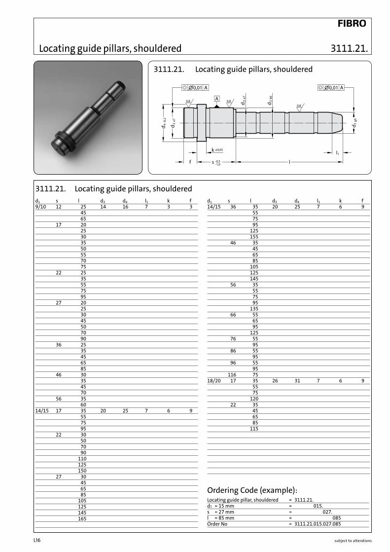
Locating guide pillars, shouldered
k
A0,80,8
0,8
±0,05
f s -0,5-1,0
l1
l-0,2
4d
e73
d
g61d
k63
d
e73
d
∅0,01 A∅0,01 A
3111.21. Locating guide pillars, shouldered
d1 s l d3 d4 l1 k f 14/15 36 35 20 25 7 6 9 55 75 95 125 155 46 35 45 65 85 105 125 145 56 35 55 75 95 135 66 55 65 95 125 76 55 95 86 55 95 96 55 95 116 75 18/20 17 35 26 31 7 6 9 55 75 120 22 35 45 65 85 115
d1 s l d3 d4 l1 k f 9/10 12 25 14 16 7 3 3 45 65 17 20 25 30 35 50 55 70 75 22 25 35 55 75 95 27 20 25 30 45 50 70 90 36 25 35 45 65 85 46 30 35 45 70 56 35 60 14/15 17 35 20 25 7 6 9 55 75 95 22 30 50 70 90 110 125 150 27 30 45 65 85 105 125 145 165
3111.21. Locating guide pillars, shouldered
Ordering Code (example):Locating guide pillar, shouldered = 3111.21.d1 = 15 mm = 3111.21.015.s = 27 mm = 3111.21.015.027.l = 85 mm = 3111.21.015.027.085Order No = 3111.21.015.027.085
3111.21.

subject to alterations L17
3111.21.
k
A0,80,8
0,8
±0,05
f s -0,5-1,0
l1
l
-0,2
4d
e73
d
g61d
k63
d
e73
d
∅0,01 A∅0,01 A
3111.21. Locating guide pillars, shouldered
d1 s l d3 d4 l1 k f 22/24 17 35 30 35 7 6 9 55 75 22 35 55 75 105 130 27 35 45 65 85 105 125 165 205 245 285 36 35 55 75 95 115 135 165 205 245 285 46 35 45 65 85 105 125 165 205 56 35 55 75 95 115 165 205
d1 s l d3 d4 l1 k f 18/20 27 35 26 31 7 6 9 45 65 85 105 125 165 225 245 36 35 55 75 95 115 135 165 225 255 46 35 45 65 85 105 135 165 245 56 35 55 75 95 155 66 35 55 75 95 145 76 55 75 95 135 86 55 75 95 125 96 55 95 116 75 115 136 135
3111.21. Locating guide pillars, shouldered
Ordering Code (example):Locating guide pillar, shouldered = 3111.21.d1 = 20 mm = 3111.21.020.s = 46 mm = 3111.21.020.046.l = 105 mm = 3111.21.020.046.105Order No = 3111.21.020.046.105
Locating guide pillars, shouldered

subject to alterationsL18
Locating guide pillars, shouldered
k
A0,80,8
0,8
±0,05
f s -0,5-1,0
l1
l-0,2
4d
e73
d
g61d
k63
d
e73
d
∅0,01 A∅0,01 A
3111.21. Locating guide pillars, shouldered
d1 s l d3 d4 l1 k f 30/32 66 55 42 47 7 6 9 75 95 115 135 175 245 295 76 55 75 95 115 155 225 86 55 75 95 115 155 225 96 55 75 95 115 155 205 116 75 115 155 136 95 115 155 156 115 155 196 155 195
d1 s l d3 d4 l1 k f 22/24 66 35 30 35 7 6 9 55 75 95 155 76 55 75 95 115 145 86 55 75 95 135 96 55 75 95 125 116 75 115 155 136 95 135 156 155 30/32 27 45 42 47 7 6 9 65 105 165 185 245 285 36 55 75 95 115 155 245 285 46 45 65 85 105 125 165 245 285 56 55 75 95 115 135 175 245 295
3111.21. Locating guide pillars, shouldered
Ordering Code (example):Locating guide pillar, shouldered = 3111.21.d1 = 32 mm = 3111.21.032.s = 86 mm = 3111.21.032.086.l = 95 mm = 3111.21.032.086.095Order No = 3111.21.032.086.095
3111.21.
subject to alterations L19
3111.21.
k
A0,80,8
0,8
±0,05
f s -0,5-1,0
l1
l
-0,2
4d
e73
d
g61d
k63
d
e73
d
∅0,01 A∅0,01 A
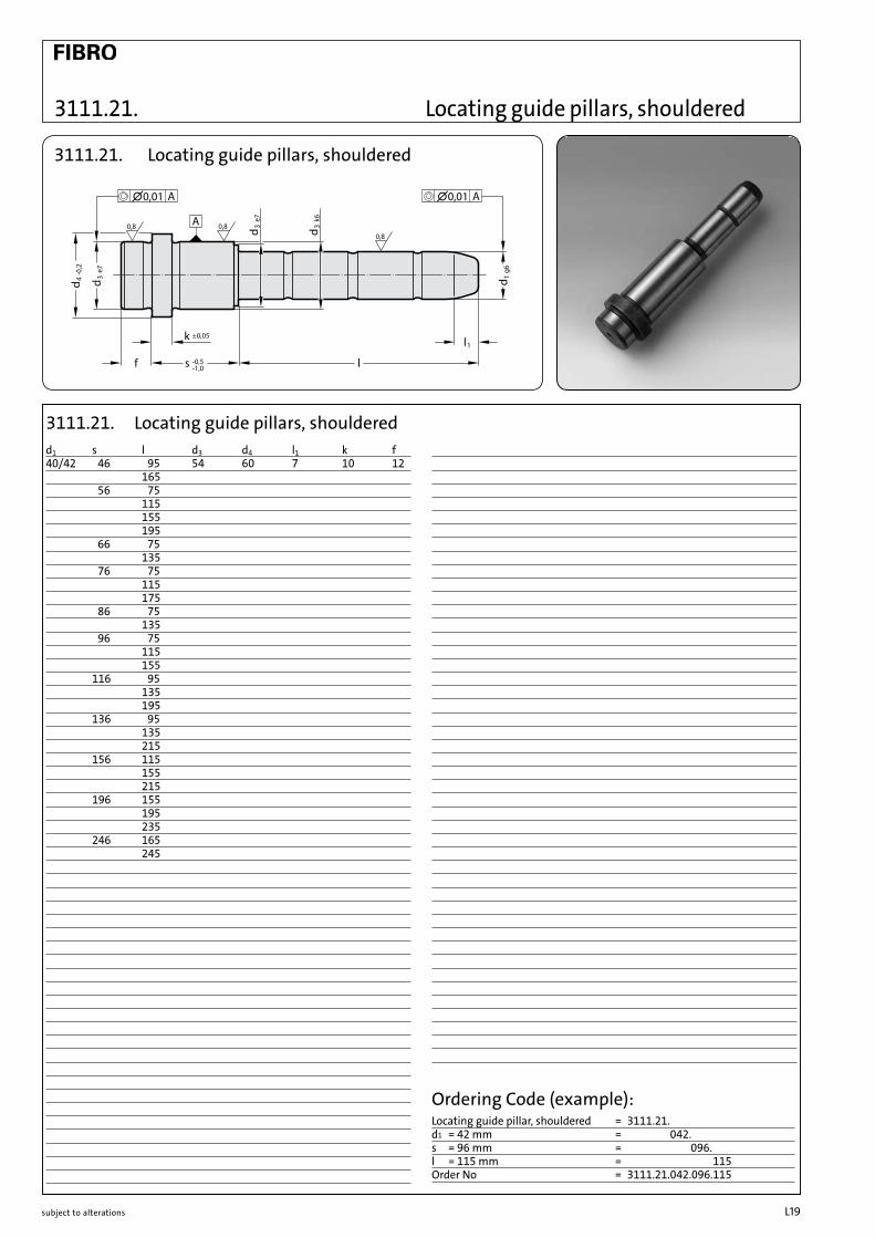
3111.21. Locating guide pillars, shouldered
d1 s l d3 d4 l1 k f 40/42 46 95 54 60 7 10 12 165 56 75 115 155 195 66 75 135 76 75 115 175 86 75 135 96 75 115 155 116 95 135 195 136 95 135 215 156 115 155 215 196 155 195 235 246 165 245
3111.21. Locating guide pillars, shouldered
Ordering Code (example):Locating guide pillar, shouldered = 3111.21.d1 = 42 mm = 3111.21.042.s = 96 mm = 3111.21.042.096.l = 115 mm = 3111.21.042.096.115Order No = 3111.21.042.096.115
Locating guide pillars, shouldered

subject to alterationsL20
d1 32 40 50 63 80d2 40 50 63 80 100d3 76 92 112 138 170d5 55 68 84 105 130d6 9 11 14 16 18d7 15 18 20 24 26r 1,6 2 2,5 2,5 3r1 4 4 5 6 8 l2 11 13 14 16 20l3 6 6 8 8 10l5 15,1 18,4 22,5 27,4 32,1l6 11 13 14 16 20l7 19 23 28 34 40l8 8 9 10 13 15l9 9 10 12 15 18l10 1,5 1,5 2 3 4l1 ( l ) ( l ) ( l ) ( l ) ( l )067 97080 110 116095 125 131 137112 142 148 154 162132 168 174 182 192160 202 210 220190 240 250224 284436 486
Ordering code (example):Guide pillar with flange = 3111.31.d1 = 32 mm = 3111.31.032.l1 = 112 mm = 3111.31.032.112Order no. = 3111.31.032.112
Guide pillars with flange
3111.31. Guide pillars with flange
3111.31. Guide pillars with flangeMaterial:SteelSurface hardness: case hardened 62+2 HRCHardness penetration depth: 1.2 mm
Execution:Ground
Note:Holding fixture bore H7. Delivery does not include screws.
Fixing:socket head screw DIN EN ISO 4762M 8 x 20 M 10 x 25 M 12 x 30 M 14 x 35 M 16 x 40should be used
radiussed
3111.31.

subject to alterations L21
Guide pillars (diagonal load pillars)
R Z 2,5
l
k -0,2l1
g61d
-0,2
4d
3110.11. Guide pillars (diagonal load pillars)
d1 8 9 10 12 14 15 16 18 20 22 24 30 32 40 50d4 10 12 12 16 18 18 20 22 24 26 28 36 36 48 58k 3 3 3 6 8 8 8 8 8 15 15 15 15 15 15l1 4 4 4 7 7 7 7 7 7 7 7 7 7 10 10
l 40 b b b b b 60 b b b b b b b b b 80 b b b b b b b b b b b 100 b b b b b b b b b b b b b 120 b b b b b b b b b b b b 140 b b b b b b b b 160 b b b b b b b b b b b b180 b b b b b b b 200 b b b b b b b b b220 b b 240 b b b b b b b b300 b b b b b b360 b b b b
3110.11. Guide pillars (diagonal load pillars)
Ordering Code (example):Guide pillar (diagonal load pillar) = 3110.11.d1 = 20 mm = 3110.11.020.l = 180 mm = 3110.11.020.180Order No = 3110.11.020.180
3110.11.
subject to alterationsL22
3100.09.
l js10
d 2
g61d
R Z4
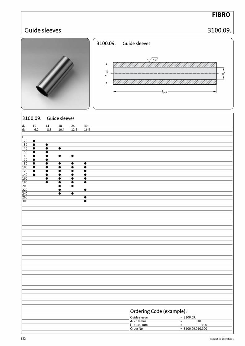
3100.09. Guide sleeves
d1 10 14 18 24 30d2 6,2 8,3 10,4 12,5 16,5
l 20 b 30 b b 40 b b b 50 b b 60 b b b b 70 b b 80 b b b b b100 b b b b b120 b b b b b140 b b b b b160 b b b b180 b b b b200 b b 220 b b240 b b 260 b300 b
3100.09. Guide sleeves
Ordering Code (example):Guide sleeve = 3100.09.d1 = 10 mm = 3100.09.010.l = 100 mm = 3100.09.010.100Order No = 3100.09.010.100
Guide sleeves
subject to alterations L23
Guide bushes
A
s -0,5-1,0 s -0,5
-1,0
k ±0,05
l
l
-0,2
4d1d
H7
1dH
7
e73d
k63d
+0,2
1d+0
,5
0,8
0,8
∅0,01 A
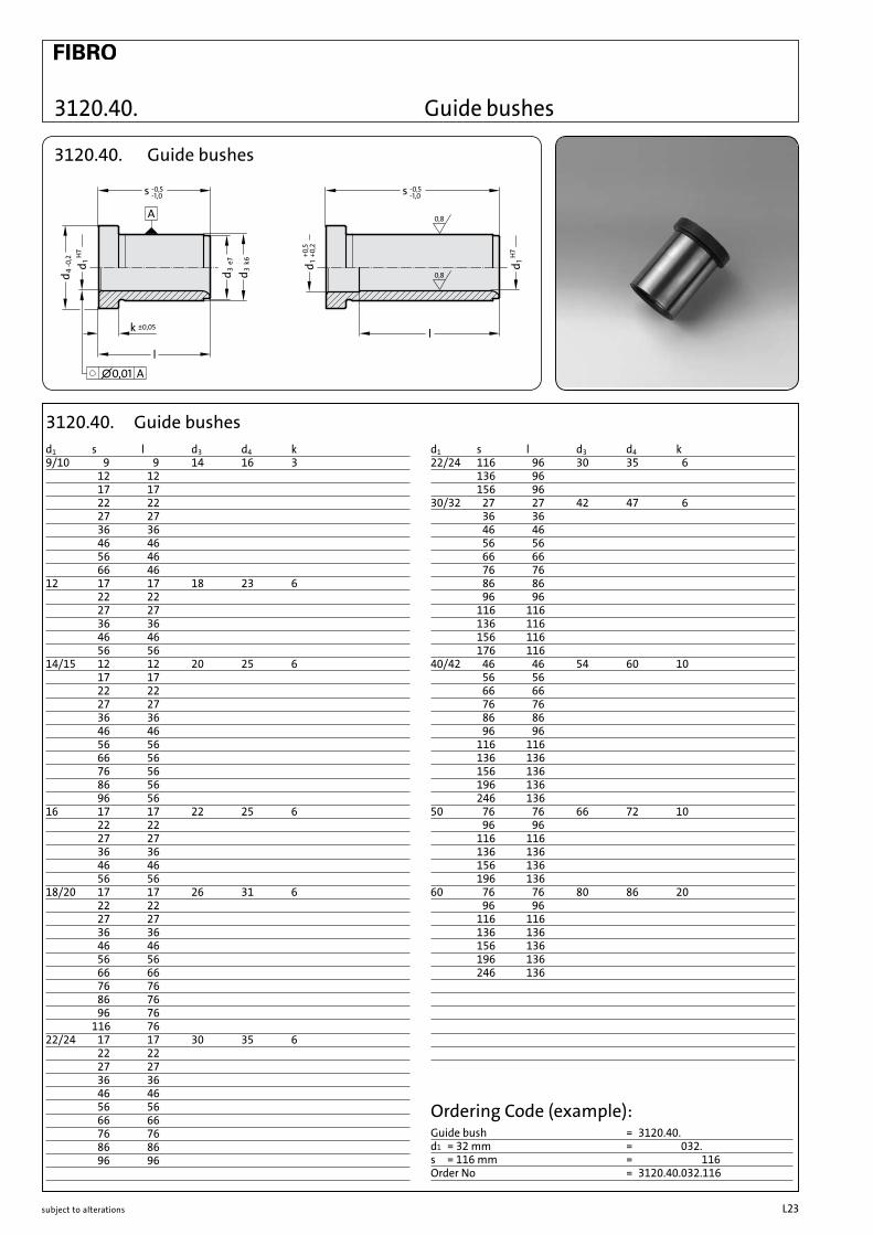
3120.40. Guide bushes
d1 s l d3 d4 k22/24 116 96 30 35 6 136 96 156 96 30/32 27 27 42 47 6 36 36 46 46 56 56 66 66 76 76 86 86 96 96 116 116 136 116 156 116 176 116 40/42 46 46 54 60 10 56 56 66 66 76 76 86 86 96 96 116 116 136 136 156 136 196 136 246 136 50 76 76 66 72 10 96 96 116 116 136 136 156 136 196 136 60 76 76 80 86 20 96 96 116 116 136 136 156 136 196 136 246 136
d1 s l d3 d4 k9/10 9 9 14 16 3 12 12 17 17 22 22 27 27 36 36 46 46 56 46 66 46 12 17 17 18 23 6 22 22 27 27 36 36 46 46 56 56 14/15 12 12 20 25 6 17 17 22 22 27 27 36 36 46 46 56 56 66 56 76 56 86 56 96 56 16 17 17 22 25 6 22 22 27 27 36 36 46 46 56 56 18/20 17 17 26 31 6 22 22 27 27 36 36 46 46 56 56 66 66 76 76 86 76 96 76 116 76 22/24 17 17 30 35 6 22 22 27 27 36 36 46 46 56 56 66 66 76 76 86 86 96 96
3120.40. Guide bushes
Ordering Code (example):Guide bush = 3120.40.d1 = 32 mm = 3120.40.032.s = 116 mm = 3120.40.032.116Order No = 3120.40.032.116
3120.40.
subject to alterationsL24
3120.42.
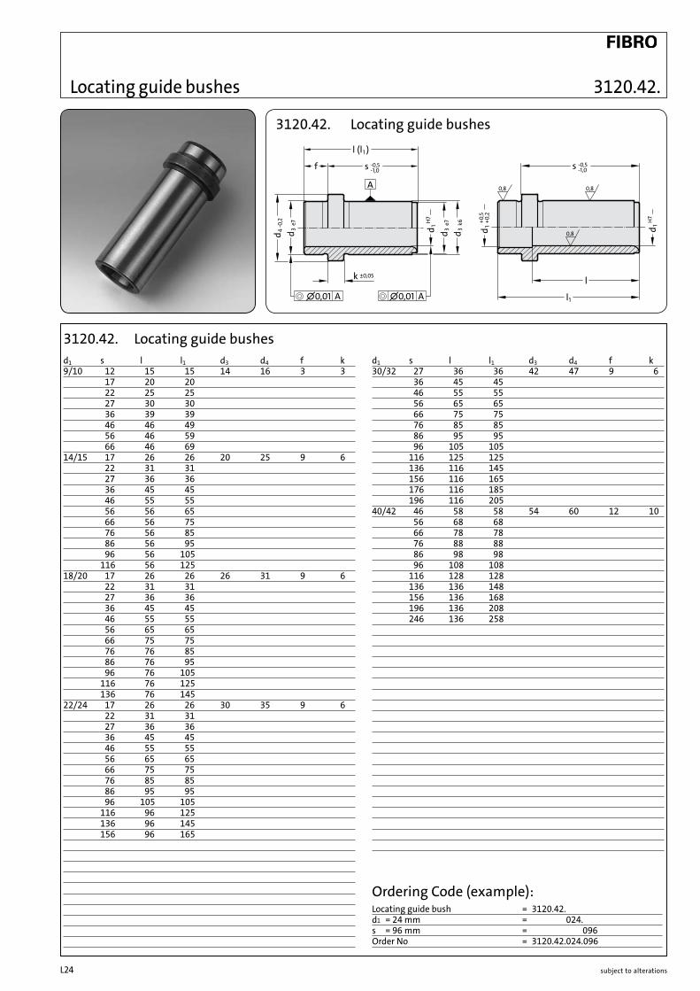
3120.42. Locating guide bushes
d1 s l l1 d3 d4 f k 30/32 27 36 36 42 47 9 6 36 45 45 46 55 55 56 65 65 66 75 75 76 85 85 86 95 95 96 105 105 116 125 125 136 116 145 156 116 165 176 116 185 196 116 205 40/42 46 58 58 54 60 12 10 56 68 68 66 78 78 76 88 88 86 98 98 96 108 108 116 128 128 136 136 148 156 136 168 196 136 208 246 136 258
d1 s l l1 d3 d4 f k 9/10 12 15 15 14 16 3 3 17 20 20 22 25 25 27 30 30 36 39 39 46 46 49 56 46 59 66 46 69 14/15 17 26 26 20 25 9 6 22 31 31 27 36 36 36 45 45 46 55 55 56 56 65 66 56 75 76 56 85 86 56 95 96 56 105 116 56 125 18/20 17 26 26 26 31 9 6 22 31 31 27 36 36 36 45 45 46 55 55 56 65 65 66 75 75 76 76 85 86 76 95 96 76 105 116 76 125 136 76 145 22/24 17 26 26 30 35 9 6 22 31 31 27 36 36 36 45 45 46 55 55 56 65 65 66 75 75 76 85 85 86 95 95 96 105 105 116 96 125 136 96 145 156 96 165
3120.42. Locating guide bushes
Ordering Code (example):Locating guide bush = 3120.42.d1 = 24 mm = 3120.42.024.s = 96 mm = 3120.42.024.096Order No = 3120.42.024.096
l (l
A
∅0,01 A ∅0,01 A
1
s -0,5
)
-1,0f
k ±0,05-0
,24d
e73d
1dH
7
e73d
k63d
0,8 0,8
0,8
s -0,5-1,0
l
l1
1dH
7
+0,2
1d+0
,5
Locating guide bushes
l (l
A
∅0,01 A ∅0,01 A
1
s -0,5
)
-1,0f
k ±0,05-0
,24d
e73d
1dH
7
e73d
k63d
0,8 0,8
0,8
s -0,5-1,0
l
l1
1dH
7
+0,2
1d+0
,5

subject to alterations L25
3120.65.
3120.65. Ball bearing guides
Ordering Code (example):Ball bearing guide = 3120.65.d1 = 18 mm = 3120.65.018.l1 = 56 mm = 3120.65.018.056Order No = 3120.65.018.056
3120.65. Ball bearing guidesd1 l l1 l2 d3 d4 f s2 Strokemax.12 24 40 2,1 22 26 6 18 50 56 8218 34 45 3 30 35 11 23 44 56 66 71 9630 54 56 4,8 46 52 21 33 32 75 78 95 110
Stro
kem
ax.
Ball Bearing Guides
subject to alterationsL26
2087.72.
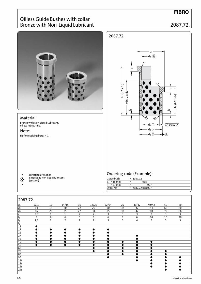
Material:Bronze with Non-Liquid Lubricant, oilless lubricating.
Note:Fit for receiving bore: H 7.
2087.72. d1 9/10 12 14/15 16 18/20 22/24 25 30/32 40/42 50 60d2 14 18 20 22 26 30 32 42 54 66 80d3 16 23 25 27 31 35 38 47 60 72 86r 0,5 1 1 2 2 3 3 3 3 3 3l3 3 6 6 6 6 6 6 6 10 10 20l4 1,5 2 2 2 2 3 3 4 5 5 5l112 ●17 ● ● ● ● ● ● 22 ● ● ● ● ● ● 27 ● ● ● ● ● ● ● 36 ● ● ● ● ● ● ● 46 ● ● ● ● ● ● ● ● ●56 ● ● ● ● ● ● ● ● ●66 ● ● ● ● ●76 ● ● ● ● ● ●86 ● ● ● ● ●96 ● ● ● ● ●116 ● ● ● ●136 ● ● ●156 ● ● ●196 ● ●
Direction of Motion Embedded non-liquid lubricant (section)
Ø0,02
2087.72.
Ordering code (Example):Guide bush = 2087.72.d1 = 18 mm = 2087.72.018.l1 = 27 mm = 2087.72.018.027Order No = 2087.72.018.027
Oilless Guide Bushes with collar Bronze with Non-Liquid Lubricant

subject to alterations L27
Oilless Guide Bushes with collar Bronze with Non-Liquid Lubricant
Ø0,02
Ø0,02
Material:Bronze with Non-Liquid Lubricant, oilless lubricating.
Note:Fit for receiving bore: H 7.
Direction of Motion Embedded non-liquid lubricant (section)
2087.70.d1 9 10 14 15 18 20 22 24 30 32 40 42d2 14 20 26 30 42 54d3 16 25 31 35 47 60l3 3 6 6 6 6 10l4 1,5 2 2 3 4 5l5 3 6 8 8 8 12r 0,5 1 2 3 3 3l1 l2
15 12 b 20 17 b 23 17 b 25 17 b b 25 22 b 28 22 b 30 22 b b 30 27 b 33 27 b 35 27 b b b 39 36 b 42 36 b 44 36 b b b 49 46 b 52 46 b 54 46 b b b 58 46 b 59 56 b 62 56 b 64 56 b b b 68 56 b 69 66 b 72 66 b 74 66 b b b 78 66 b 82 76 b 84 76 b b b 88 76 b 92 86 b 94 86 b b b 98 86 b104 96 b b b108 96 b124 116 b b b128 116 b144 136 b b148 136 b164 156 b168 156 b208 196 b
Ordering Code (example):Guide bush = 2087.70.d1 = 18 mm = 018.l2 = 27 mm = 027Order No = 2087.70.018.027
2087.70.
2087.70.
subject to alterationsL28
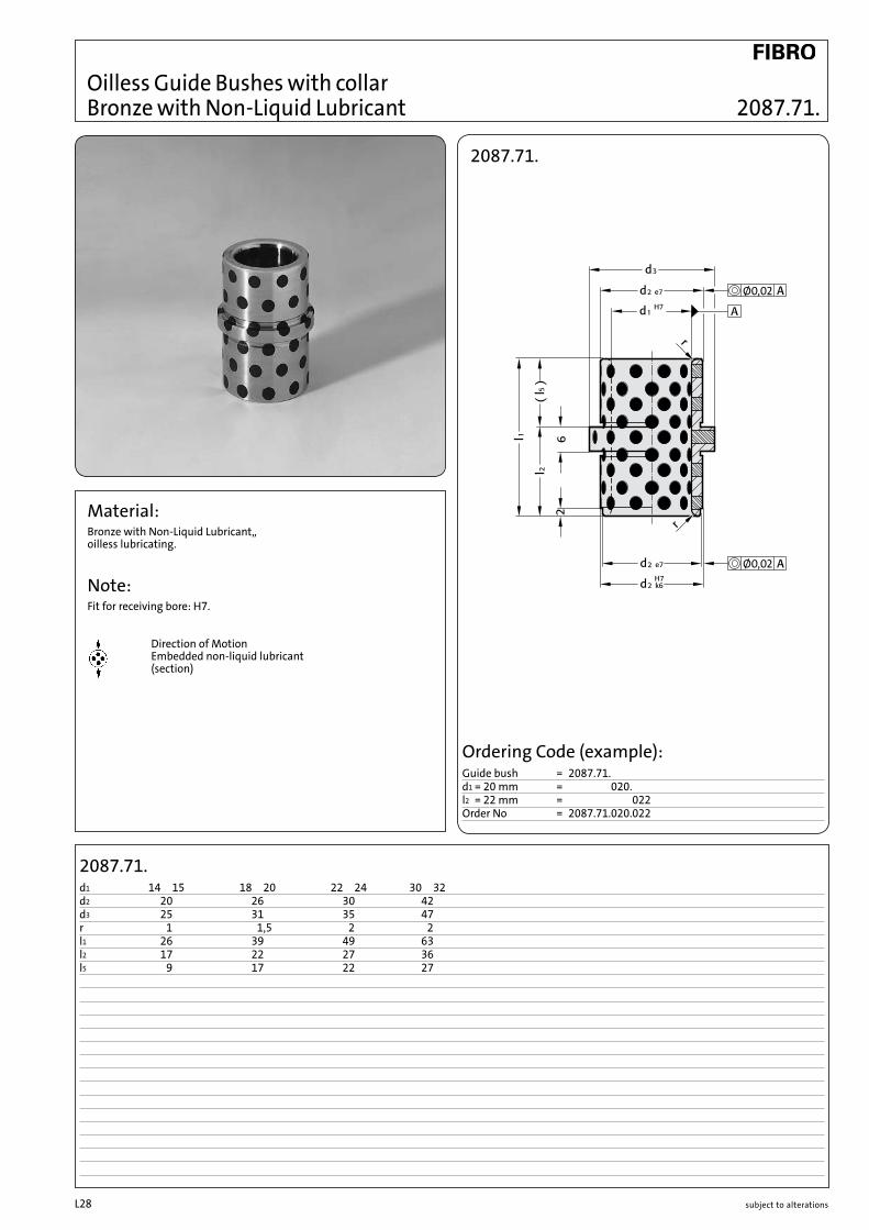
Material:Bronze with Non-Liquid Lubricant,, oilless lubricating.
Note:Fit for receiving bore: H7.
Direction of Motion Embedded non-liquid lubricant (section)
2087.71.d1 14 15 18 20 22 24 30 32d2 20 26 30 42d3 25 31 35 47r 1 1,5 2 2l1 26 39 49 63l2 17 22 27 36l5 9 17 22 27
Oilless Guide Bushes with collar Bronze with Non-Liquid Lubricant
2087.71.
Ø0,02
Ø0,02
Ordering Code (example):Guide bush = 2087.71.d1 = 20 mm = 2032.70.020.l2 = 22 mm = 2032.70.020.022Order No = 2087.71.020.022
2087.71.

subject to alterations L29
2087.73.
Material:Bronze with non-liquid lubricant, oilless lubricating.
Note:Fit for receiving bore: H7.
2087.73.d1 25 30 40 50 60 63d2 35 42 50 63 80 80d3 40 47 60 72 86 90r1 3 3 4 4 3 4r2 2 2 2 3 3 3l4 11,5 11,5 18,5 18,5 24,5 28,5 21,5 31,5 29,5 37,5l3 7,5 7,5 6 8 7,5 8l2 24 24 35,5 39,5 44,5 55,5 49 55,5 62,5 62,5l1 43 43 60 64 77 92 78 95 100 108
Direction of Motion Embedded non-liquid lubricant (section)
2087.73.
Ordering Code (example):Guide Bush = 2087.73.d1 = 25 mm = 2087.73.025.l1 = 43 mm = 2087.73.025.043Order No = 2087.73.025.043
Oilless Guide Bushes with centre collar Bronze with Non-Liquid Lubricant

subject to alterationsL30
3120.70. / 3120.71. d1 8 10 12 13 14 15 16 18 19 20 24 25 28 30 31,5 32 35 38 40 45d2 12 14/15 18 19 20 21 22 24 25 26/28/30 32 32/33/35 38 38/40/42 40 42 44/45 48 50/55 55/56/60r 0,5 0,5 0,5 0,5 0,5 0,75 0,75 0,75 0,75 0,75 0,75 0,75 0,75 0,75 0,75 0,75 0,75 1,5 1,5 1,5l4 2 2 2 2 2 2 2 2 4 4 4 4 4 4 4 4 4 4 4 4l1 8 b b/– 10 b b/b b b b b b 12 b b/– b b b b 15 b b/– b b b b b b –/ b/– 16 b b b b b –/ b/b – /b/b 20 b/– b b b b b b –/ b/b – /b/b b/b/– – /b b/– 25 b b b b b –/ b/b – /b/b b/b/– b/b b/b 30 b b b b b –/ b/b – /b/b b b/b/– b b b/b b b/b b/b/b 35 b b –/ b/b – /b/b b/b/– b/b b/b b/b/b 37 b –/ b/– 40 b b b/b/b – /b/b b b/b/– b b b/b b b/b b/b/b 47 b – /b/– 50 –/ b/– b/b/b b/b/– b/b b/b b/b/b 60 – /b/– b/b/b b b/b b/b b/b/b 70 b/– –/–/b 77 b b/– 80 b/– –/–/b
3120.70. 3120.71.
Material:3120.70. Bronze with Non-Liquid lubricant, oilless lubricating 3120.71. Bronze
Note:Recommended holding fixture bore H7. Bushes can be used radially and axially.
Fixing:Connecting with adhesive or if needed secure with threaded pin or flat mushroom head screw 2192.61.
Direction of Motion Embedded non-liquid lubricant (section)
3120.70.
3120.71.
Ordering Code (example):Guide bush = 3120.70.d1 = 40 mm = 3120.70.040.d2 = 50 mm = 3120.70.040.050l1 = 80 mm = 3120.70.040.050.080Order number = 3120.70.040.050.080
Ordering Code (example):Guide bush = 3120.71.d1 = 40 mm = 3120.71.040.d2 = 50 mm = 3120.71.040.050l1 = 80 mm = 3120.71.040.050.080Order number = 3120.71.040.050.080
Oilless Guide bushes Bronze with Non-Liquid lubricant Bronze

subject to alterations L31
Guide bushes Bronze with Non-Liquid lubricant Bronze
3120.70.
3120.71.
Material:3120.70. Bronze with Non-Liquid lubricant, low maintenance. 3120.71. Bronze
Note:Recommended holding fixture bore H7. Bushes can be used radially and axially.
Fixing:Connecting with adhesive or if needed secure with threaded pin or flat mushroom head screw 2192.61.
Direction of Motion Embedded non-liquid lubricant (section)
Ordering Code (example):Guide bush = 3120.70.d1 = 40 mm = 3120.70.040.d2 = 50 mm = 3120.70.040.050l1 = 80 mm = 3120.70.040.050.080Order number = 3120.70.040.050.080
Ordering Code (example):Guide bush = 3120.71.d1 = 40 mm = 3120.71.040.d2 = 50 mm = 3120.71.040.050l1 = 80 mm = 3120.71.040.050.080Order number = 3120.71.040.050.080
3120.70. / 3120.71. d1 50 55 60 63 65 70 75 80 85 90 100 110 120 125 130 140 150 160d2 60/62/65 70 74/75 75 80 85/90 90/95 96/100 100 110 120 130 140 145 150 160 170 180r 1,5 2 2 2 2 2 2 2 2 2 2 2 2 2 2 2 2 2l4 4 4 4 4 4 4 4 4 4 4 4 4 4 4 4 4 4 4l1 30 b/b/b b/b 35 b/b/– b/b b/– 37 40 b/b/b b b/b b/– b/b 47 50 b/b/b b b/b b b/b b/b 60 b/b/b b b/b b b b/b b/b b/b b b 70 b/b/b b b/b b b b/b b/b b/b b b 77 80 b/–/b b/b b b b/b b/b b/b b b b b b 95 b/–/– 100 –/–/b –/b b/– b/b b/b b b b b b b b b b 120 b b/b b b b b b b 130 b 140 – /b b b b 150 b b
3120.70. 3120.71.

subject to alterationsL32
Rectangular Guides
3131.40.
Material:Steel with solid lubricant surface: case hardened 580+40 HV 30Steel surface: case hardened 700+60 HV 30Operating temperature up to 200°C.
3131.40. Order No l2 b2 l1 r t3 t2 t1 d2 d1 l4 l3 b3 b1
3131.40.022.016.020 22 16 20 6 11 6,8 20 11 6,6 7 15 26 40.040 40
3131.40.027.020.025 27 20 25 6 13 6,8 22 11 6,6 7 19 31 45.025 50
3131.40.036.025.032 36 25 32 8 14 6,8 25 11 6,6 9 27 35 50.063 63
3131.40.046.032.040 46 32 40 8 19 9 32 15 9 11 35 45 63.080 80
3131.40.056.040.050 56 40 50 10 22 11 36 18 11 15 40 60 85.100 100
3131.40.066.050.056 66 50 56 10 24 13 40 20 14 18 48 74 100.112 112
Ordering Code (example):Rectangular guide = 3131.40.l2 = 22 mm = 3131.40.022.b2 = 16 mm = 3131.40.022.016.l1 = 40 mm = 3131.40.022.016.040Order no. = 3131.40.022.016.040
3131.40.

subject to alterations L33
3131.80.
3131.80.
Material:Steel Hardness: ~56-58 HRC Surface: burnished
Description:The rectangular guides with rollers guarantee the greatest precisionwhen their mould is moved together. The rectangular guides must always be installed in the outer area of the mould plates to ensure problem-free functionality.The maximum operating temperature is 150°C.Advantages: no play or friction, low maintenance and no lubrication
3131.80. Order No t w a b c d e h r s1 s2 s3 d1 d2 t1
3131.80.032.063 32 63 46 46 27 21 12,1 92 8 9 11 35 15 9 93131.80.040.100 40 100 66 66 36 33 19,5 132 10 13 18 48 20 13,5 13
Ordering Code (example):Rectangular guide with rollers = 3131.80.t = 32 mm = 3131.80.032.w = 63 mm = 3131.80.032.063Order number = 3131.80.032.063
Rectangular Guides with Rollers

subject to alterationsL34

subject to alterations L35
Forming / Demoulding

subject to alterationsL36
Material:Guide strips: Bronze with non-liquid lubrication bolt fixture: C45, burnished
Description:Profiled guide for individual assembly of inclined bolt guides, low maintenance.Bolt fixture with rotating bearing for work angle up to max. 30°.Model 2967.11.ll.00.2 with adjusting mechanism for inclined bolts.Order socket head screws ISO 4762 separately.Delivery includes a locking pin as a guide piece anti-twist protection of guide pillar.
2967.11.ll.00.1 / 2967.11.ll.00.2 Socket headOrder No ød w w1 l l1 s h øc ør d1 d2 t t1 e f rh x y srew2967.11.08.00.1 8 24 12 25 – 13 16 20 7 5 8 3,5 – – – – 8 — M 4x102967.11.10.00.1 10 28 14 32 – 17 16 20 8 6 10 3 – – – – 8 — M 5x122967.11.12.00.1 12 31 17 40 – 20 20 25 10 7 12 3,5 – – – – 10 — M 6x162967.11.16.00.1 16 36 21 45 – 24 24 30 14 9 16 5 – – – – 12 — M 8x202967.11.20.00.1 20 43 28 45 – 24 30 40 14 11 20 7 – – – – 15 — M10x252967.11.25.00.1 25 48 33 50 – 26 35 45 14 14 25 8 – – – – 17,5 — M12x302967.11.30.00.1 30 55 38 60 – 30 38 50 16 14 25 7,5 – – – – 19 — M12x302967.11.35.00.1 35 64 44 70 – 34 40 55 18 14 25 8 – – – – 20 — M12x302967.11.40.00.1 40 72 50 80 – 38 43 60 20 18 32 8 – – – – 21,5 — M16x35 2967.11.16.00.2 16 36 21 45 42 24 24 30 14 9 – – 6 14 17 21 12 15 M 8x602967.11.20.00.2 20 43 28 45 45 24 30 40 13 11 – – 6 19 22 21 15 18,5 M10x602967.11.25.00.2 25 48 33 50 49 26 35 45 16 13 – – 7 22 27 21,5 17,5 20,5 M12x702967.11.30.00.2 30 55 38 60 55 30 38 50 18 13 – – 7 27 32 26 19 22 M12x702967.11.35.00.2 35 64 44 70 58 34 40 55 18 14 – – 7 32 36 28 20 23 M12x802967.11.40.00.2 40 72 50 80 60,5 38 43 60 20 17 – – 7 38 41 29 21,5 24,5 M16x90
2967.11.ll.00.2 with adjusting screw
Ordering Code (example):Profiled guide = 2967.11ød = 16 mm = 2967.11.16Slide angle = 0° = 2967.11.16.00with adjusting screw = 2 = 2967.11.16.00.2Order numbera = 2967.11.16.00.2
2967.11.ll.00.1 Standard
Ordering Code (example):Profiled guide = 2967.11.ød = 8 mm = 2967.11.08.Slide angle = 0° = 2967.11.08.00.Standard = 1 = 2967.11.08.00.1Order number = 2967.11.08.00.1
Sliders for transverse bolt guides2967.11.ll.00.1 2967.11.ll.00.2
subject to alterations L37
2967.10.
2967.10.
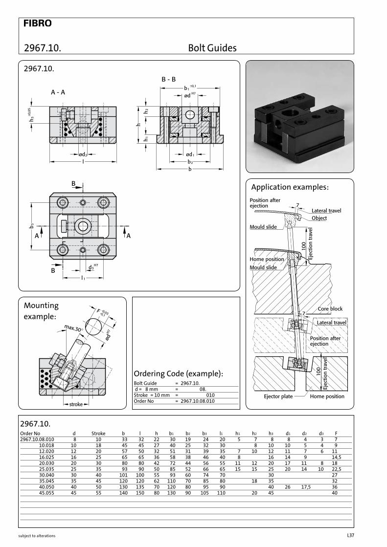
2967.10.08.010 8 10 33 32 22 30 19 24 20 5 7 8 8 4 3 72967.10.10.018 10 18 45 45 27 40 25 32 30 8 10 10 5 4 92967.10.12.020 12 20 57 50 32 51 31 39 35 7 10 12 11 7 6 112967.10.16.025 16 25 65 65 36 58 38 46 40 8 16 14 9 14,52967.10.20.030 20 30 80 80 42 72 44 56 55 11 12 20 17 11 8 182967.10.25.035 25 35 93 90 50 85 52 66 65 15 15 25 20 14 10 22,52967.10.30.040 30 40 101 100 55 93 60 74 70 30 272967.10.35.045 35 45 120 120 62 110 70 85 80 18 35 322967.10.40.050 40 50 130 135 70 120 80 95 90 40 26 17,5 362967.10.45.055 45 55 140 150 80 130 90 105 110 20 45 40
Order No Ød Stroke b l h b1 b2 b3 l1 h1 h2 h3 Ød1 Ød2 Ød3 F
Application examples:
2967.10.
Mountingexample:
Ordering Code (example):Bolt Guide = 2967.10.Ød = 8 mm = 2967.10.08.Stroke = 10 mm = 2967.10.08.010Order No = 2967.10.08.010
Bolt Guides

subject to alterationsL38
237.1. l1 d1 d2 k r 40 63 80 100 125 160 200 250 315 400 500 630 800 1000 1250 1600 1 2,5 1,2 0,2 b b b b b b b 1,1 b b b b b b b 1,2 b b b b b b b 1,3 3 1,5 b b b b b b b 1,4 b b b b b b b 1,5 b b b b b b b 1,6 b b b b b b b 1,7 b b b b b b b 1,8 b b b b b b b 1,9 b b b b b b b 2 4 2 b b b b b b b b b 2,2 b b b b b b 2,5 5 0,3 b b b b b b b b b 2,7 b b b b b b 3 6 3 b b b b b b b b b b b 3,2 b b b b b b b 3,5 7 b b b b b b b 3,7 b b b b b b b 4 8 b b b b b b b b b b b 4,2 b b b b b b b 4,5 b b b b b b b 4,7 b b b b b b b 5 10 b b b b b b b b b b b b b 5,2 b b b b b b b b 5,5 b b b b b b b b 6 12 5 0,5 b b b b b b b b b b b b b 6,2 b b b b b b b b b 6,5 b b b b b b b b 7 b b b b b b b b b 8 14 b b b b b b b b b b b b b b b 8,2 b b b b b b b b b b 8,5 b b b b b b b b b 9 b b b b b b b b b 10 16 b b b b b b b b b b b b b b 10,2 b b b b b b b b b 10,5 b b b b b b b b b 11 b b b b b b b 12 18 7 0,8 b b b b b b b b b b b b 12,2 b b b b b b b 12,5 b b b b b b b b b 14 22 b b b b b b b b b b b b 16 b b b b b b b b b b b 18 24 b b b b b b b 20 26 8 1,0 b b b b b b b b b
Hardened Ejector Pins - DIN ISO 6751
237.1. Material:WS Order No: 237.1. Hardness: Shaft 60±2 HRC Head 45±5 HRC
Execution:DIN ISO 6751 Shank hardened and precision ground. Head hot upset-forged.
Description of FIBRO materials for tool and die components see pages E 10–E 11.
Ordering Code (example):Ejector Pin = 237.Material WS = 237.1.d1 = Ø 4,0 mm = 237.1.0400.l1 = 200 mm = 237.1.0400.200Order No = 237.1.0400.200
237.1.

subject to alterations L39
237.8.
Material:NWAOrder No: 237.8. Hardness: Shaft* ^950 HV 0,3 Head 45±5 HRC Tensile Strength (core) L1400 N/mm2
Execution:DIN ISO 6751 Shank nitrided and precision ground. Head hot upset-forged.* Owing to thinness of nitrided skin, hardness testing on shank restricted to Vickers only. Test load = 3 N max.
l1 d1 d2 k r 100 125 160 200 250 315 400 500 630 800 1000 1,5 3 1,5 0,2 b b b b 2 4 2 b b b b b 2,2 b b b b 2,4 5 2 b b b b b b 2,5 0,3 b b b b b b 2,7 b b b b 2,9 b b b b b b 3 6 3 b b b b b b b b 3,2 b b b b b b b 3,4 b b b b b b 3,5 7 b b b b b b b 3,7 b b b b b b b 3,9 b b b b b b 4 8 b b b b b b b b 4,2 b b b b b b b 4,4 b b b b b b 4,5 b b b b b b b 4,7 b b b b b b 4,9 b b b b b b 5 10 b b b b b b b b b b 5,2 b b b b b b b b 5,4 b b b b b b 5,5 b b b b b b b b 5,7 b b b b b b 5,9 b b b b b b 6 12 5 0,5 b b b b b b b b b b 6,2 b b b b b b b b b 6,5 b b b b b b b b 6,7 b b b b b b 6,9 b b b b b b 7 b b b b b b b b b 7,2 b b b b b b 7,8 b b b b b b 8 14 b b b b b b b b b b b 8,2 b b b b b b b b b b 8,4 b b b b b b 8,5 b b b b b b b b b 9 b b b b b b b b b 9,7 b b b b b b 10 16 b b b b b b b b b b b 10,2 b b b b b b b b b b 10,5 b b b b b b b b b 11 b b b b b b b b b 12 18 7 0,8 b b b b b b b b b b b 12,2 b b b b b b b b b b 12,5 b b b b b b b b b b 14 22 b b b b b b b b b b b 16 b b b b b b b b b b b 18 24 b b b b b b b b b 20 26 8 1,0 b b b b b b b b b 25 32 10 b b b b b b b b 32 40 b b b b b b b b
237.8.
Ordering Code (example):Ejector Pin = 237.Material NWA = 237.8.d1 = Ø 2,50 mm = 237.8.0250.l1 = 160 mm = 237.8.0250.160Order No = 237.8.0250.160
237.8.
Description of FIBRO materials for tool and die components see pages E 10–E 11.
Hotwork Precision Ejector Pins - Nitrided DIN ISO 6751

subject to alterationsL40
Hardened Ejector Pins DIN ISO 8694
238.1.
Material:WSOrder No: 238.1.Hardness: Shaft 60±2 HRC Head 45±5 HRC
Execution:DIN ISO 8694, Shank hardened and precision ground. Head hot upset-forged.
238.1. l1 63 80 100 125 160 200 d1 d2 d3 k l2 30 32 50 50 63 80 0,8 4 2 2 b b b b b 0,9 b b b b b 1 b b b b b b 1,1 b b b b b b 1,2 b b b b b b 1,3 b b b b b b 1,4 b b b b b b 1,5 6 3 3 b b b b b b 1,6 b b b b b 1,7 b b b b b 1,8 b b b b b 1,9 b b b b b 2 b b b b b 2,1 b b b b 2,2 b b b b b 2,3 b b b b 2,4 b b b b 2,5 b b b b
Ordering Code (example):Ejector Pin = 238.1.0150.125Material WS = 238.1.0150.125d1 = [ 1,5 mm = 238.1.0150.125l1 = 125 mm = 238.1.0150.125Order No = 238.1.0150.125
Description of FIBRO materials for tool and die components see pages E 10–E 11.
238.1.
subject to alterations L41
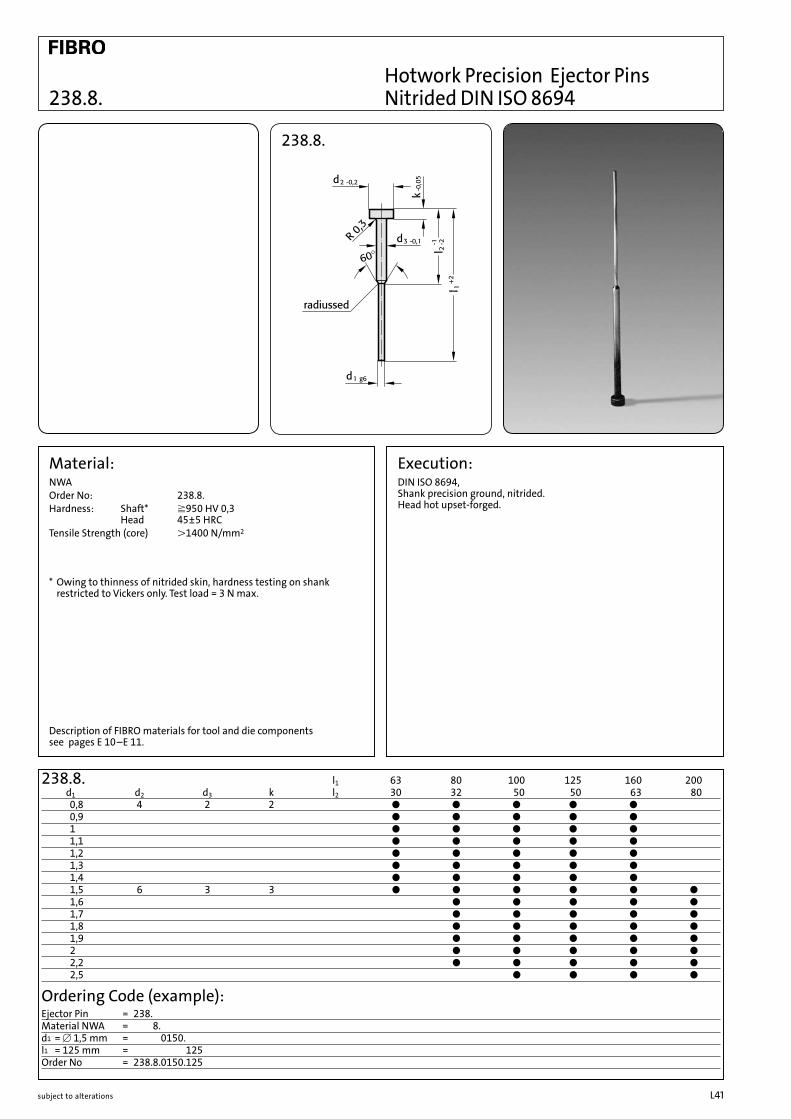
238.8.
238.8.
Material:NWAOrder No: 238.8.Hardness: Shaft* ^950 HV 0,3 Head 45±5 HRCTensile Strength (core) L1400 N/mm2
* Owing to thinness of nitrided skin, hardness testing on shank restricted to Vickers only. Test load = 3 N max.
Execution:DIN ISO 8694, Shank precision ground, nitrided. Head hot upset-forged.
l1 63 80 100 125 160 200 d1 d2 d3 k l2 30 32 50 50 63 80 0,8 4 2 2 b b b b b 0,9 b b b b b 1 b b b b b 1,1 b b b b b 1,2 b b b b b 1,3 b b b b b 1,4 b b b b b 1,5 6 3 3 b b b b b b 1,6 b b b b b 1,7 b b b b b 1,8 b b b b b 1,9 b b b b b 2 b b b b b 2,2 b b b b b 2,5 b b b b
238.8.
Ordering Code (example):Ejector Pin = 238.Material NWA = 238.8.d1 = [ 1,5 mm = 238.8.0150.l1 = 125 mm = 238.8.0150.125Order No = 238.8.0150.125
Description of FIBRO materials for tool and die components see pages E 10–E 11.
Hotwork Precision Ejector Pins Nitrided DIN ISO 8694
subject to alterationsL42
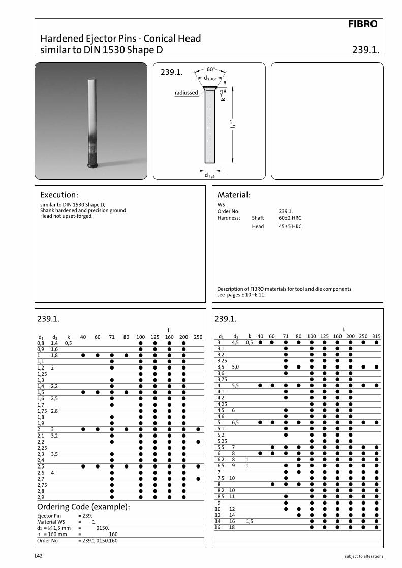
Hardened Ejector Pins - Conical Head similar to DIN 1530 Shape D
239.1.
Material:WSOrder No: 239.1.Hardness: Shaft 60±2 HRC Head 45±5 HRC
Execution:similar to DIN 1530 Shape D, Shank hardened and precision ground. Head hot upset-forged.
239.1. l1 d1 d2 k 40 60 71 80 100 125 160 200 250 0,8 1,4 0,5 b b b b 0,9 1,6 b b b b 1 1,8 b b b b b b b b 1,1 b b b b b 1,2 2 b b b b b 1,25 b b b b 1,3 b b b b b 1,4 2,2 b b b b b 1,5 b b b b b b b b 1,6 2,5 b b b b b 1,7 b b b b b 1,75 2,8 b b b b 1,8 b b b b b 1,9 b b b b b 2 3 b b b b b b b b b 2,1 3,2 b b b b b 2,2 b b b b b b 2,25 b b b b 2,3 3,5 b b b b b 2,4 b b b b b 2,5 b b b b b b b b b 2,6 4 b b b b b 2,7 b b b b b b 2,75 b b b b b 2,8 b b b b b2,9 b b b b b
239.1. l1 d1 d2 k 40 60 71 80 100 125 160 200 250 315 3 4,5 0,5 b b b b b b b b b b 3,1 b b b b b 3,2 b b b b b 3,25 b b b b b 3,5 5,0 b b b b b b b b 3,6 b b b b b 3,75 b b b b 4 5,5 b b b b b b b b b b 4,1 b b b b b 4,2 b b b b b 4,25 b b b b 4,5 6 b b b b b 4,6 b b b b b 5 6,5 b b b b b b b b b b 5,1 b b b b b 5,2 b b b b b 5,25 b b b b 5,5 7 b b b b b b b b b 6 8 b b b b b b b b b b 6,2 8 1 b b b b b b b 6,5 9 1 b b b b b b b b 7 b b b b b b b b 7,5 10 b b b b b b b 8 b b b b b b b b b 8,2 10 b b b b b b 8,5 11 b b b b b b b 9 b b b b b b b 10 12 b b b b b b b b 12 14 b b b b b b b 14 16 1,5 b b b b b b 16 18 b b b b b b
Ordering Code (example):Ejector Pin = 239.1.0150.160Material WS = 238.1.0150.160d1 = [ 1,5 mm = 238.1.0150.160l1 = 160 mm = 238.1.0150.160Order No = 239.1.0150.160
239.1.
Description of FIBRO materials for tool and die components see pages E 10–E 11.

subject to alterations L43
239.8.
Material:NWAOrder No: 239.8.Hardness: Shaft* ^950 HV 0,3 Head 45±5 HRCTensile Strength (core): L1400 N/mm2
* Owing to thinness of nitrided skin, hardness testing on shank restricted to Vickers only. Test load = 3 N max.
239.8. l1 d1 d2 k 100 125 160 200 250 315 3 4,5 0,5 b b b b b 4 5,5 b b b b b b 5 6,5 b b b b b b 6 8 b b b b b b 8 10 1 b b b b b b 10 12 b b b b b b 12 14 b b b b b b 14 16 1,5 b b b b 16 18 b b b b
Ordering Code (example):Ejector Pin = 239.Material NWA = 239.8.d1 = [ 6,0 mm = 239.8.0600.l1 = 160 mm = 239.8.0600.160Order No = 239.8.0600.160
Execution:similar to DIN 1530 Shape D.Shank precision ground, nitrided.Head hot upset-forged.
239.8.
Hotwork Precision Ejector Pins Nitrided - similar to DIN 1530 Shape D
Description of FIBRO materials for tool and die components see pages E 10–E 11.

subject to alterationsL44
263.1. 4 4,2 4,2 4,2 5 5 5 6 6 6 6 8 8 8 10 10 12 12 8 8 8 8 10 10 10 12 12 12 12 14 14 14 16 16 18 18 3 3 3 3 3 3 3 5 5 5 5 5 5 5 5 5 7 7 0,3 0,3 0,3 0,3 0,3 0,3 0,3 0,5 0,5 0,5 0,5 0,5 0,5 0,5 0,5 0,5 0,8 0,8 1 0,8 1 1,2 1 1,2 1,5 1,0 1,2 1,5 2 1,2 1,5 2 1,5 2 2 2,5 3,5 3,8 3,8 3,8 4,5 4,5 4,5 5,5 5,5 5,5 5,5 7,5 7,5 7,5 9,5 9,5 11,5 11,5
b b b b b b b b b b b b b b b b b b b b b b b b b b b b b b b b b b b b b b b b b b b b b b b b b b b b b b b b b b b b b b b b b b b b b b b b b
Special dimensions a and b available on request.
263.1.d1d2kra b
l1 l2 l3 l4 63 30 25 10 80 40 30 10100 50 40 10125 60 50 15160 80 50 30200 100 60 40250 125 60 65315 160 70 85
263.1.
Blade Precision Ejectors - Hardened similar to DIN ISO 8693
Material:WSOrder No: 263.1.Hardness: Shaft 60±2 HRC Head 45±5 HRC
Execution:Blade and Shank hardened and precision ground.Head hot upset-forged.
Ordering Code (example):Blade Ejector = 263.Material WS = 263.1.a 3 b = 1,535,5 mm = 263.1.15.055.l1 = 125 mm = 263.1.15.055.125Order No = 263.1.15.055.125
Description of FIBRO materials for tool and die components see pages E 10–E 11.
263.1.

subject to alterations L45
Material:NWAOrder No: 263.8.Hardness: Shaft* ^ 950 HV 0,3 Head 45±5 HRCTensile Strength (core): > 1400 N/mm2
* Owing to thinness of nitrided skin, hardness testing on shank restricted to Vickers only. Test load = 3 N max.
Execution:Blade and Shank precision ground and nitrided. Head hot upset-forged.
4 4,2 4,2 4,2 5 5 5 6 6 6 6 8 8 8 10 10 12 12 16 16 8 8 8 8 10 10 10 12 12 12 12 14 14 14 16 16 18 18 22 22 3 3 3 3 3 3 3 5 5 5 5 5 5 5 5 5 7 7 7 7 0,3 0,3 0,3 0,3 0,3 0,3 0,3 0,5 0,5 0,5 0,5 0,5 0,5 0,5 0,5 0,5 0,8 0,8 0,8 0,8 1 0,8 1 1,2 1 1,2 1,5 1,0 1,2 1,5 2 1,2 1,5 2 1,5 2 2 2,5 2 2,5 3,5 3,8 3,8 3,8 4,5 4,5 4,5 5,5 5,5 5,5 5,5 7,5 7,5 7,5 9,5 9,5 11,5 11,5 15,5 15,5
b b b b b b b b b b b b b b b b b b b b b b b b b b b b b b b b b b b b b b b b b b b b b b b b b b b b b b b b b b b b b b b b b b b b b b b b b b b b b b b
Ordering Code (example):Blade Ejector = 263.Material NWA = 263.8.a 3 b = 1,0 3 3,5 mm = 263.8.10.035.l1 = 100 mm = 263.8.10.035.100Order No = 263.8.10.035.100
263.8
263.8.
263.8.d1
d2krab
l1 l2 l3 l4 63 30 25 10 80 40 30 10100 50 40 10125 60 50 15160 80 50 30200 100 60 40250 125 60 65315 160 70 85400 200 95 105
Special dimensions a and b available on request.
Description of FIBRO materials for tool and die components see pages E 10–E 11.
Hotwork Blade Precision Ejectors - Nitrided similar to DIN ISO 8693
subject to alterationsL46
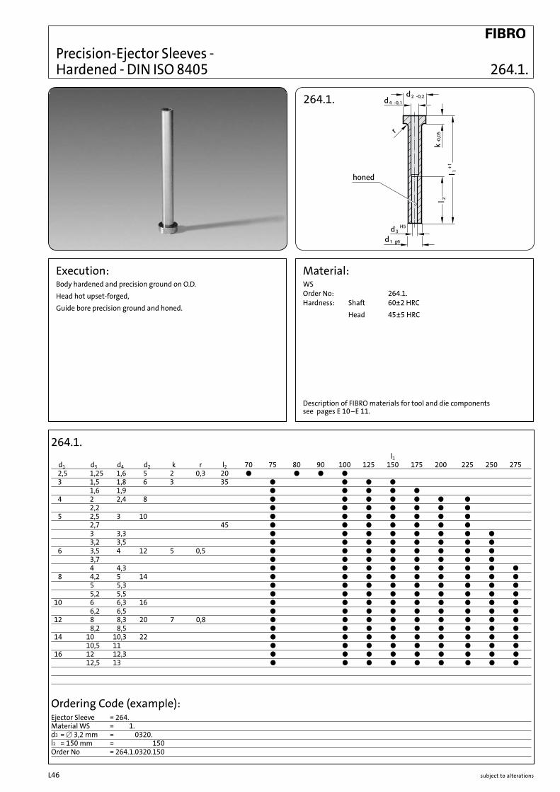
Precision-Ejector Sleeves - Hardened - DIN ISO 8405
264.1.
Material:WSOrder No: 264.1.Hardness: Shaft 60±2 HRC Head 45±5 HRC
Execution:Body hardened and precision ground on O.D.Head hot upset-forged,Guide bore precision ground and honed.
264.1. l1 d1 d3 d4 d2 k r l2 70 75 80 90 100 125 150 175 200 225 250 275 2,5 1,25 1,6 5 2 0,3 20 b b b b 3 1,5 1,8 6 3 35 b b b b 1,6 1,9 b b b b b 4 2 2,4 8 b b b b b b b 2,2 b b b b b b b 5 2,5 3 10 b b b b b b b 2,7 45 b b b b b b b 3 3,3 b b b b b b b b 3,2 3,5 b b b b b b b b 6 3,5 4 12 5 0,5 b b b b b b b b 3,7 b b b b b b b b 4 4,3 b b b b b b b b b 8 4,2 5 14 b b b b b b b b b 5 5,3 b b b b b b b b b 5,2 5,5 b b b b b b b b b 10 6 6,3 16 b b b b b b b b b 6,2 6,5 b b b b b b b b b 12 8 8,3 20 7 0,8 b b b b b b b b b 8,2 8,5 b b b b b b b b b 14 10 10,3 22 b b b b b b b b b 10,5 11 b b b b b b b b b 16 12 12,3 b b b b b b b b b 12,5 13 b b b b b b b b b
Ordering Code (example):Ejector Sleeve = 264.Material WS = 264.1.d3 = [ 3,2 mm = 264.1.0320.l1 = 150 mm = 264.1.0320.150Order No = 264.1.0320.150
Description of FIBRO materials for tool and die components see pages E 10–E 11.
264.1.

subject to alterations L47
264.8.
Material:NWAOrder No 264.8.Hardness: Shaft* and Bore ^950 HV 0,3 Head 45±5 HRCTensile Strength (core): L1400 N/mm2
* Owing to thinness of nitrided skin, hardness testing on shank restricted to Vickers only. Test load = 3 N max.
Execution:Body nitrided and precision ground on O.D.Head hot upset-forged.Guide bore precision ground and honed.
264.8. l1 d1 d3 d4 d2 k r l2 75 100 125 150 175 200 225 250 275 3 1,5 1,8 6 3 0,3 35 b b b b 1,6 1,9 b b b b 4 2 2,4 8 b b b b 2,2 b b b b 5 2,5 3 10 b b b b 2,7 45 b b b b 3 3,3 b b b b b 3,2 3,5 b b b b b 6 3,5 4 12 5 0,5 b b b b b 3,7 b b b b b 4 4,3 b b b b b b 8 4,2 5 14 b b b b b b 5 5,3 b b b b b b 5,2 5,5 b b b b b b 10 6 6,3 16 b b b b b b b b 6,2 6,5 b b b b b b b b 12 8 8,3 20 7 0,8 b b b b b b b b b 8,2 8,5 b b b b b b b b b 14 10 10,3 22 b b b b b b b b 10,2 10,5 b b b b b b b b 16 12 12,3 b b b b b b b b
Ordering Code (example):Ejector Sleeve, nitrided = 264.Material NWA = 264.8.d3 = [ 3,2 mm = 264.8.0320.l = 150 mm = 264.8.0320.150Order No = 264.8.0320.150
264.8.
Description of FIBRO materials for tool and die components see pages E 10–E 11.
Hotwork Precision Ejector Sleeves - Nitrided - DIN ISO 8405
subject to alterationsL48
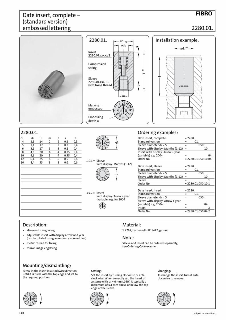
Date insert, complete – (standard version) embossed lettering
Installation example:2280.01.
2280.01.d1 d2 l m t s a 4 2,5 14 2 2 0,2 0,3 5 3,1 17 3 3 0,2 0,4 6 3,1 17 3 3 0,2 0,4 8 4,6 20 4 4 0,35 0,410 4,6 20 5 4 0,35 0,412 6,4 25 6 6 0,5 0,616 8,4 33 8 8 0,6 0,6
Ordering examples:Date insert, complete = 2280.Standard version = 2280.01.Sleeve diameter d1 = 5 = 2280.01.050.Sleeve with display: Months (1-12) = 2280.01.050.10.Insert with display: Arrow + year (variable) e.g. 2004 = 2280.01.050.10.04Order No = 2280.01.050.10.04
Date insert, Sleeve = 2280.Standard version = 2280.01.Sleeve diameter d1 = 5 = 2280.01.050.Sleeve with display: Months (1-12) = 2280.01.050.10.Sleeve = 2280.01.050.10.1Order No = 2280.01.050.10.1
Date insert, Insert = 2280.Standard version = 2280.01.Sleeve diameter d1 = 5 = 2280.01.050.Sleeve with display: Arrow + year (variable) e.g. 2004 = 2280.01.050.04.Insert = 2280.01.050.04.2Order No = 2280.01.050.04.2
Description:• sleevewithengraving• adjustableinsertwithdisplayarrowandyear
(can be rotated using an ordinary srcrewdriver)• metricthreadforfixing• mirrorimageengraving
Mounting/dismantling:Screw in the insert in a clockwise direction until it is flush with the top edge and set to the required position.
Setting:Set the insert by turning clockwise or anti-clockwise. When correctly set, the insert of a stamp with d1 = 6 mm (.060.) is typically a maximum of 0.1 mm above or below the top edge of the sleeve.
Changing:To change the insert turn it anti- clockwise to remove.
Material:1.2767, hardened HRC 54±2, ground
Note:Sleeve and Insert can be ordered separately, see Ordering Code examle.
.10.1 = Sleeve with display: Months (1-12)
.xx.2 = Insert with display: Arrow + year (variable) e.g. for 2004
2280.01.

subject to alterations L49
Installation example: 2280.02.
2280.02.d1 d2 l s a 2,6 1,4 4 0,2 0,3 3 1,5 4 0,2 0,3 4 2,1 5 0,25 0,3 5 3,1 8 0,2 0,4 6 3,1 8 0,2 0,4 8 4,4 10 0,25 0,410 5,2 12 0,35 0,412 6,2 14 0,35 0,6
Ordering examples:Date insert, complete = 2280.short version = 2280.02.Sleeve diameter d1 = 5 = 2280.02.050.Sleeve with display: Months (1-12) = 2280.02.050.10.Insert with display: Arrow + year (variablel) e.g. 2004 = 2280.02.050.10.04Order No = 2280.02.050.10.04
Date insert, Sleeve = 2280.short version = 2280.02.Sleeve diameter d1 = 5 = 2280.02.050.Sleeve with display: Months (1-12) = 2280.02.050.10.Sleeve = 2280.02.050.10.1Order No = 2280.02.050.10.1
Date insert, Insert = 2280.short version = 2280.02.Sleeve diameter d1 = 5 = 2280.02.050.Sleeve with display: Arrow + year (variable) e.g. 2004 = 2280.02.050.04.Insert = 2280.02.050.04.2Order No = 2280.02.050.04.2
Description:• sleevewithengraving• adjustableinsertwithdisplayarrowandyear
(can be rotated using an ordinary srcrewdriver)• metricthreadforfixing• mirrorimageengraving
Mounting/dismantling:Fixing:Screw in the insert in a clockwise direction until it is flush with the top edge and set to the required position.
Setting:Set the insert by turning clockwise or anti-clockwise. When correctly set, the insert of a stamp with d1 = 6 mm (.060.) is typically a maximum of 0.1 mm above or below the top edge of the sleeve.
Changing:To change the insert turn it anti- clockwise to remove.
Material:1.2767, hardened HRC 54±2, ground
Note:Sleeve and Insert can be ordered separately, see Ordering Code examle.
.10.1 = Sleeve with display: Months (1-12)
.xx.2 = Insert with display: Arrow + year (variable) e.g. for 2004
2280.02.
Date insert, complete – (short version) embossed lettering
Transition fit

subject to alterationsL50
Quill holders for core tempering
3820.10.Quill holder for core tempering
Installation options1. Swivelled 2. Swivelled 3. Not swivelled 4. Not swivelled Slider without sealing surfaces Slider with sealing surfaces Slider without sealing surfaces Slider with sealing surfaces
Material:3820.10.Quill holder: stainless steel
Description:The quill holder is preferably used with bolt guide 2967.10. and quills with internal bore for slider tempering. 4 connections make it possible to implement tempering circuits either directly or in series.
3820.10.Order No d d7 d8 d5 b l l1 l2 l3 l43820.01.025.025 25 25 65 22 60 100 26 45 19 133820.01.030.030 30 30 70 27 65 105 31 50 22 14,53820.01.040.040 40 40 80 37 70 115 41 60 28 16,5 Ordering code (example):
Quil holder = 3820.10.d = 25 mm = 025.d7 = 25 mm = 025Order No = 3820.10.025.025
3820.10.

subject to alterations L51
3800.01.01.01.Order No d1 d2 for3800.01.01.01.0240.301) 24 3 3820.10.025.0253800.01.01.01.0210.302) 21 33800.01.01.01.0292.301) 29,2 3 3820.10.030.0303800.01.01.01.0260.302) 26 33800.01.01.01.0392.301) 39,2 3 3820.10.040.0403800.01.01.01.0360.302) 36 3
3800.01.01.01.
Ordering code (example):O-ring = 3800.01.01.01.d1 = 24 mm = 0240.d2 = 3 mm = 30Order No = 3800.01.01.01.0240.30
3800.01.01.01.
Material:Viton® (FPM)
Note:Operating temperature -15°C to +200°C
O-Rings

subject to alterationsL52

subject to alterations L53
Mould Line Gas Springs and Spring Plungers for Mould Making

subject to alterationsL54
FML Gas Springs for Mould Making 3487.

subject to alterations L55
All FIBRO Gas Springs meet the requirements of the Pressure Equipment Directive 97/23/EC.
The Pressure Equipment Directive (97/23/EC) has been ratified by the European Parliament and the Council of Europe. The requirements of the Pressure Equipment Directive came into force throughout the EC on 29 May 2002.The directive defines pressure equipment as vessels, pipework, safety devices and pressure accessories. In terms of the Directive a vessel is a casing which is designed and manufactured to contain fluids under pressure.It follows from this definition that nitrogen Gas Springs of all sizes are deemed to be pressure vessels and must in this respect comply with the Pressure Equipment Directive (97/23/EC) from 29 May 2002.
3487.
FIBRO Mould Line Gas Springs (FML)FIBRO FML Gas Springs are an ideal supplement to and expansion of the traditional FIBRO product lines of helical, disc and elastomer springs for manufacturing tools, devices, moulds and machines.Gas Springs can be used for all applications where lift movements are required in parallel to mould opening.FIBRO Mould Line Gas Springs (FML), which were specially developed for mould making, are characterised by their high force, small size, long service life and a constant operating temperature of 120°C.Of course, FIBRO FML Gas Springs are approved as per European Pressure Equipment Directive 97/23/EC (14th GSGV ordinance on pressure vessels). FIBRO FML Gas Springs are filled with nitrogen and do not require any pressure space that is positioned externally or in tool plates. They also require no gas supply lines.In certain special cases, however, monitoring of charge pressure in the installed state is required. These may be found in the list of accessory products if needed. As long as all mounting details are laid out with due circumspection, it is no problem at all to remove and install FIBRO FML Gas Springs.Operating instructions are included with every delivery of FIBRO FML Gas Springs. An application example is shown on page L57.
FunctioningThe pressure medium is a commercially available, environment-friendly nitrogen. FIBRO FML Gas Springs have a standard charge pressure of max. 150 bar.
Pressure Build-UpIn operation the piston rod enters the spring space whose volume is progressively reduced. The resulting pressure rise can be plotted on the Gas Spring Diagram as a multiplication factor. The spring force is the product of initial force times that pressure-rise factor and can therefore be calculated easily.
Working TemperatureThe spring temperature should not exceed +120°C.
Charge PressureModification of charge pressure allows varia tion of the force rating and can be predetermined from the spring Diagram.
InstallationFIBRO FML Gas Springs can be used in any installation position. Whether or not external forces act on them when at rest is of no consequence.and can therefore be calculated easily.
FML Gas Springs for Mould Making

subject to alterationsL56
MaintenanceFIBRO FML Gas Springs are designed for long-term main-tenance-free operation. We recommend lightly oiling the piston rod before using. Sealing and guide elements can be replaced easily in very little time.They are available in a spare parts kit.Each spare parts kit comes with detailed instructions for maintenance of Gas Springs.
Caution!Gas Springs may only be charged with commercial Grade 5.0 nitrogen gas.
AccessoriesThe range of accessories for Gas Springs includes faste-ning devices, charging and control units, screw connec-tions and lines for setting up compound systems.
Advantages of theFIBRO Mould Line series:• Very little calibration work required in the tool• No lubrication required• No maintenance required for up to 1,000,000 strokes1
• Variably adjustable forces• For mould temperatures of up to 120°C• Approved as per the European Pressure Equipment Directive 97/23/EC (14th GSGV regulation for pressure vessels)• Standard safety features (FIBRO Safer Choice)2
Safety piston rod Excess pressure protection Overstroke protection• A pressure monitoring system makes it possible to recognise an impending failure at an early point (prevention)• No tool breakage if the 2nd separation level is locked (the plate comes to a standstill; after the jam is removed, production can be resumed)• Used worldwide in one million FIBRO Gas Springs• Cost savings: approximately 60-70% (e.g. compared to a latch-locking unit)
1 At 80°C to 120°C/ 500,000 strokes2 Depending on type of spring
Warning SignsThese are available on request. The signs should be affixed near the springs in as prominent a position as possible.
FML Gas Springs for Mould Making
Size 35x50 mmLanguage Order No
german 2480.00.035.050.1
english 2480.00.035.050.2
french 2480.00.035.050.3
italien 2480.00.035.050.4
spanish 2480.00.035.050.5
Size 75x105 mmlanguage Order No
german 2480.00.075.105.1
english 2480.00.075.105.2
french 2480.00.075.105.3
italian 2480.00.075.105.4
spanish 2480.00.075.105.5
Size110x150 mmlanguage Order No
german 2480.00.110.150.1
english 2480.00.110.150.2
french 2480.00.110.150.3
italian 2480.00.110.150.4
spanish 2480.00.110.150.5
3487.

subject to alterations L57
Fastened with 2480.055./057./064.1) from Ø38: Ø+0,5
F110
Änd
erun
gen
vorb
ehal
ten
ø+1 +0,5ø
ø+1 +0,5ø
OKOK
OKOK
OK
OKOK
2·17580·2002·1°
Einb
au-R
icht
linie
nvo
nG
asdr
uckf
eder
n
Einb
aube
ispi
ele
Nac
hste
hend
wer
den
Einb
aum
öglic
hkei
ten
von
Gas
druc
kfed
ern
aufg
efüh
rt.
Wei
tere
Einb
auin
form
atio
nen
entn
ehm
enSi
ebi
tte
den
ents
prec
hend
enSe
iten
des
Kata
loge
s.
Lose
inB
ohru
ngei
nges
etzt
Bod
ense
itig
vers
chra
ubt
mit
2480
.011
.
Bef
estig
tm
it24
80.0
55./
057.
Bef
estig
tm
it24
80.0
07./
008.
Bef
estig
tm
it24
80.0
07./
008.
Bef
estig
tm
it24
80.0
44./
045.
/047
.B
efes
tigt
mit
2480
.022
.
ok
3487.
Mounting examplesMounting possibilities for Gas Springs are listed below.For additional information on mounting, see the corresponding pages in the catalogue.
F110
Änd
erun
gen
vorb
ehal
ten
ø+1 +0,5ø
ø+1 +0,5ø
OKOK
OKOK
OK
OKOK
2·17580·2002·1°
Einb
au-R
icht
linie
nvo
nG
asdr
uckf
eder
n
Einb
aube
ispi
ele
Nac
hste
hend
wer
den
Einb
aum
öglic
hkei
ten
von
Gas
druc
kfed
ern
aufg
efüh
rt.
Wei
tere
Einb
auin
form
atio
nen
entn
ehm
enSi
ebi
tte
den
ents
prec
hend
enSe
iten
des
Kata
loge
s.
Lose
inB
ohru
ngei
nges
etzt
Bod
ense
itig
vers
chra
ubt
mit
2480
.011
.
Bef
estig
tm
it24
80.0
55./
057.
Bef
estig
tm
it24
80.0
07./
008.
Bef
estig
tm
it24
80.0
07./
008.
Bef
estig
tm
it24
80.0
44./
045.
/047
.B
efes
tigt
mit
2480
.022
.
Screw mounted at the base Screw mounted at the base with 2480.011.
F110Änderungenvorbehalten
ø+1+0,5ø
ø+1+0,5ø
OKOKOKOK
OK
OKOK
2·17580·2002·1
°
Einbau-RichtlinienvonGasdruckfedern
EinbaubeispieleNachstehendwerdenEinbaumöglichkeitenvonGasdruckfedernaufgeführt.WeitereEinbauinformationenentnehmenSiebittedenentsprechendenSeitendesKataloges.
LoseinBohrungeingesetzt
Bodenseitigverschraubtmit2480.011.
Befestigtmit2480.055./057.Befestigtmit2480.007./008.
Befestigtmit2480.007./008.Befestigtmit2480.044./045./047.Befestigtmit2480.022.
F110Änderungenvorbehalten
ø+1+0,5ø
ø+1+0,5ø
OKOKOKOK
OK
OKOK
2·17580·2002·1
°
Einbau-RichtlinienvonGasdruckfedern
EinbaubeispieleNachstehendwerdenEinbaumöglichkeitenvonGasdruckfedernaufgeführt.WeitereEinbauinformationenentnehmenSiebittedenentsprechendenSeitendesKataloges.
LoseinBohrungeingesetzt
Bodenseitigverschraubtmit2480.011.
Befestigtmit2480.055./057.Befestigtmit2480.007./008.
Befestigtmit2480.007./008.Befestigtmit2480.044./045./047.Befestigtmit2480.022.Fastened with 2480.044./045./047.
ok
ok ok
F110
Änd
erun
gen
vorb
ehal
ten
ø+1 +0,5ø
ø+1 +0,5ø
OKOK
OKOK
OK
OKOK
2·17580·2002·1°
Einb
au-R
icht
linie
nvo
nG
asdr
uckf
eder
n
Einb
aube
ispi
ele
Nac
hste
hend
wer
den
Einb
aum
öglic
hkei
ten
von
Gas
druc
kfed
ern
aufg
efüh
rt.
Wei
tere
Einb
auin
form
atio
nen
entn
ehm
enSi
ebi
tte
den
ents
prec
hend
enSe
iten
des
Kata
loge
s.
Lose
inB
ohru
ngei
nges
etzt
Bod
ense
itig
vers
chra
ubt
mit
2480
.011
.
Bef
estig
tm
it24
80.0
55./
057.
Bef
estig
tm
it24
80.0
07./
008.
Bef
estig
tm
it24
80.0
07./
008.
Bef
estig
tm
it24
80.0
44./
045.
/047
.B
efes
tigt
mit
2480
.022
.
Installation principle:
1)
+2
Installation instructions FML Gas Springs

subject to alterationsL58
Änd
erun
gen
vorb
ehal
ten
F111
Einb
au-R
icht
linie
nvo
nG
asdr
uckf
eder
n
F
OK
min
.0°C
Um
eine
best
mög
liche
Lebe
nsda
uer
und
Sich
erhe
itde
rG
asdr
uckf
eder
nzu
gew
ährle
iste
n,m
üsse
ndi
eEi
nbau
richt
linie
nbe
folg
tw
erde
n.
Einb
auan
wei
sung
•W
enn
mög
lich,
Sich
ern
der
Gas
druc
kfed
erim
Wer
kzeu
g/M
asch
ine
unte
rVe
rwen
dung
der
imFe
derb
oden
eing
ebra
chte
nG
ewin
debo
hrun
gen
oder
Bef
estig
ungs
elem
ente
.D
iem
ax.A
nzug
sdre
hmom
ente
für
die
Gew
inde
imG
asdr
uckf
eder
bode
nsi
ndzu
beac
hten
:(M
6=
10N
m;M
8=
24N
m;M
10=
45N
m;M
12=
80N
m)
•D
ieG
ewin
debo
hrun
gin
der
Kolb
enst
ange
darf
nich
tzu
rB
efes
tigun
gde
rG
asdr
uckf
eder
verw
ende
tw
erde
n.Si
edi
ent
auss
chlie
ßlic
hnu
rzu
War
tung
szw
ecke
n.•
Gas
druc
kfed
erni
cht
inei
ner
Art
und
Wei
seei
nset
zen,
dass
die
Kolb
enst
ange
abru
ptau
sde
rge
drüc
kten
Posi
tion
frei
wird
(inn
ere
Bes
chäd
igun
gde
rG
asdr
uckf
eder
).•
Gas
druc
kfed
erpa
ralle
lzur
Kraf
tein
leitu
ngei
nbau
en.
•Ko
nta
ktob
erflä
che
zur
Bet
ätig
ung
der
Kolb
enst
ange
mus
sre
chtw
inkl
igzu
mG
asdr
uckf
eder
hub
sein
und
sollt
eei
nehi
nrei
chen
deH
ärte
aufw
eise
n.•
Esdü
rfen
kein
ese
itlic
heKr
äfte
auf
die
Gas
druc
kfed
erw
irken
.•
Kolb
enst
ange
gege
nm
echa
nisc
heB
esch
ädig
ung
und
Kont
akt
mit
Flüs
sigk
eite
nsc
hütz
en.
•Es
wird
empf
ohle
n,ei
neH
ubre
serv
evo
n10
%de
rno
min
elle
nH
ublä
nge
oder
5m
mvo
rzus
ehen
.•
Der
max
imal
eFü
lldru
ck(b
ei20
°C)
darf
nich
tüb
ersc
hritt
enw
erde
n,da
anso
nste
nke
ine
Syst
emsi
cher
heit
gew
ährle
iste
tw
erde
nka
nn.
•Ei
nÜ
bers
chre
iten
der
max
.zul
ässi
gen
Arbe
itste
mpe
ratu
rve
rrin
gert
die
Lebe
nsda
uer
der
Gas
druc
kfed
erw
esen
tlich
.•
Die
Obe
rflä
che
der
Kolb
enst
ange
/de
sKo
lben
sso
llte
kom
plet
tbe
aufs
chla
gtw
erde
n.•
Entf
erne
nSi
edi
eAd
apte
r-B
oden
plat
te24
80.0
0.20
von
der
Gas
druc
kfed
er24
90.1
2.n
urin
druc
klo-
sem
Zust
and.
max
.1,6
m/s
bzw
.0,5
m/s
1)
min
.0,5
–3
mm
2)
1)je
nach
Fede
rtyp
2)Ü
bers
tand
beiv
oll
genu
tzte
mH
ub
max
.80
°Cbz
w.1
80°C
1)
max
.150
bar
(20
°C)
bzw
.180
bar1
)
N2
2·17585·2002·1°
°
To achieve the best possible service life and safety for the Gas Springs, the installation instructions must be followed. Mounting instructions
Änd
erun
gen
vorb
ehal
ten
F111
Einb
au-R
icht
linie
nvo
nG
asdr
uckf
eder
n
F
OK
min
.0°C
Um
eine
best
mög
liche
Lebe
nsda
uer
und
Sich
erhe
itde
rG
asdr
uckf
eder
nzu
gew
ährle
iste
n,m
üsse
ndi
eEi
nbau
richt
linie
nbe
folg
tw
erde
n.
Einb
auan
wei
sung
•W
enn
mög
lich,
Sich
ern
der
Gas
druc
kfed
erim
Wer
kzeu
g/M
asch
ine
unte
rVe
rwen
dung
der
imFe
derb
oden
eing
ebra
chte
nG
ewin
debo
hrun
gen
oder
Bef
estig
ungs
elem
ente
.D
iem
ax.A
nzug
sdre
hmom
ente
für
die
Gew
inde
imG
asdr
uckf
eder
bode
nsi
ndzu
beac
hten
:(M
6=
10N
m;M
8=
24N
m;M
10=
45N
m;M
12=
80N
m)
•D
ieG
ewin
debo
hrun
gin
der
Kolb
enst
ange
darf
nich
tzu
rB
efes
tigun
gde
rG
asdr
uckf
eder
verw
ende
tw
erde
n.Si
edi
ent
auss
chlie
ßlic
hnu
rzu
War
tung
szw
ecke
n.•
Gas
druc
kfed
erni
cht
inei
ner
Art
und
Wei
seei
nset
zen,
dass
die
Kolb
enst
ange
abru
ptau
sde
rge
drüc
kten
Posi
tion
frei
wird
(inn
ere
Bes
chäd
igun
gde
rG
asdr
uckf
eder
).•
Gas
druc
kfed
erpa
ralle
lzur
Kraf
tein
leitu
ngei
nbau
en.
•Ko
nta
ktob
erflä
che
zur
Bet
ätig
ung
der
Kolb
enst
ange
mus
sre
chtw
inkl
igzu
mG
asdr
uckf
eder
hub
sein
und
sollt
eei
nehi
nrei
chen
deH
ärte
aufw
eise
n.•
Esdü
rfen
kein
ese
itlic
heKr
äfte
auf
die
Gas
druc
kfed
erw
irken
.•
Kolb
enst
ange
gege
nm
echa
nisc
heB
esch
ädig
ung
und
Kont
akt
mit
Flüs
sigk
eite
nsc
hütz
en.
•Es
wird
empf
ohle
n,ei
neH
ubre
serv
evo
n10
%de
rno
min
elle
nH
ublä
nge
oder
5m
mvo
rzus
ehen
.•
Der
max
imal
eFü
lldru
ck(b
ei20
°C)
darf
nich
tüb
ersc
hritt
enw
erde
n,da
anso
nste
nke
ine
Syst
emsi
cher
heit
gew
ährle
iste
tw
erde
nka
nn.
•Ei
nÜ
bers
chre
iten
der
max
.zul
ässi
gen
Arbe
itste
mpe
ratu
rve
rrin
gert
die
Lebe
nsda
uer
der
Gas
druc
kfed
erw
esen
tlich
.•
Die
Obe
rflä
che
der
Kolb
enst
ange
/de
sKo
lben
sso
llte
kom
plet
tbe
aufs
chla
gtw
erde
n.•
Entf
erne
nSi
edi
eAd
apte
r-B
oden
plat
te24
80.0
0.20
von
der
Gas
druc
kfed
er24
90.1
2.n
urin
druc
klo-
sem
Zust
and.
max
.1,6
m/s
bzw
.0,5
m/s
1)
min
.0,5
–3
mm
2)
1)je
nach
Fede
rtyp
2)Ü
bers
tand
beiv
oll
genu
tzte
mH
ub
max
.80
°Cbz
w.1
80°C
1)
max
.150
bar
(20
°C)
bzw
.180
bar1
)
N2
2·17585·2002·1°
°
max. 1,0 m/s
Änd
erun
gen
vorb
ehal
ten
F111
Einb
au-R
icht
linie
nvo
nG
asdr
uckf
eder
n
F
OK
min
.0°C
Um
eine
best
mög
liche
Lebe
nsda
uer
und
Sich
erhe
itde
rG
asdr
uckf
eder
nzu
gew
ährle
iste
n,m
üsse
ndi
eEi
nbau
richt
linie
nbe
folg
tw
erde
n.
Einb
auan
wei
sung
•W
enn
mög
lich,
Sich
ern
der
Gas
druc
kfed
erim
Wer
kzeu
g/M
asch
ine
unte
rVe
rwen
dung
der
imFe
derb
oden
eing
ebra
chte
nG
ewin
debo
hrun
gen
oder
Bef
estig
ungs
elem
ente
.D
iem
ax.A
nzug
sdre
hmom
ente
für
die
Gew
inde
imG
asdr
uckf
eder
bode
nsi
ndzu
beac
hten
:(M
6=
10N
m;M
8=
24N
m;M
10=
45N
m;M
12=
80N
m)
•D
ieG
ewin
debo
hrun
gin
der
Kolb
enst
ange
darf
nich
tzu
rB
efes
tigun
gde
rG
asdr
uckf
eder
verw
ende
tw
erde
n.Si
edi
ent
auss
chlie
ßlic
hnu
rzu
War
tung
szw
ecke
n.•
Gas
druc
kfed
erni
cht
inei
ner
Art
und
Wei
seei
nset
zen,
dass
die
Kolb
enst
ange
abru
ptau
sde
rge
drüc
kten
Posi
tion
frei
wird
(inn
ere
Bes
chäd
igun
gde
rG
asdr
uckf
eder
).•
Gas
druc
kfed
erpa
ralle
lzur
Kraf
tein
leitu
ngei
nbau
en.
•Ko
nta
ktob
erflä
che
zur
Bet
ätig
ung
der
Kolb
enst
ange
mus
sre
chtw
inkl
igzu
mG
asdr
uckf
eder
hub
sein
und
sollt
eei
nehi
nrei
chen
deH
ärte
aufw
eise
n.•
Esdü
rfen
kein
ese
itlic
heKr
äfte
auf
die
Gas
druc
kfed
erw
irken
.•
Kolb
enst
ange
gege
nm
echa
nisc
heB
esch
ädig
ung
und
Kont
akt
mit
Flüs
sigk
eite
nsc
hütz
en.
•Es
wird
empf
ohle
n,ei
neH
ubre
serv
evo
n10
%de
rno
min
elle
nH
ublä
nge
oder
5m
mvo
rzus
ehen
.•
Der
max
imal
eFü
lldru
ck(b
ei20
°C)
darf
nich
tüb
ersc
hritt
enw
erde
n,da
anso
nste
nke
ine
Syst
emsi
cher
heit
gew
ährle
iste
tw
erde
nka
nn.
•Ei
nÜ
bers
chre
iten
der
max
.zul
ässi
gen
Arbe
itste
mpe
ratu
rve
rrin
gert
die
Lebe
nsda
uer
der
Gas
druc
kfed
erw
esen
tlich
.•
Die
Obe
rflä
che
der
Kolb
enst
ange
/de
sKo
lben
sso
llte
kom
plet
tbe
aufs
chla
gtw
erde
n.•
Entf
erne
nSi
edi
eAd
apte
r-B
oden
plat
te24
80.0
0.20
von
der
Gas
druc
kfed
er24
90.1
2.n
urin
druc
klo-
sem
Zust
and.
max
.1,6
m/s
bzw
.0,5
m/s
1)
min
.0,5
–3
mm
2)
1)je
nach
Fede
rtyp
2)Ü
bers
tand
beiv
oll
genu
tzte
mH
ub
max
.80
°Cbz
w.1
80°C
1)
max
.150
bar
(20
°C)
bzw
.180
bar1
)
N2
2·17585·2002·1°
°
max. 150 bar (20°C) N2
Änd
erun
gen
vorb
ehal
ten
F111
Einb
au-R
icht
linie
nvo
nG
asdr
uckf
eder
n
F
OK
min
.0°C
Um
eine
best
mög
liche
Lebe
nsda
uer
und
Sich
erhe
itde
rG
asdr
uckf
eder
nzu
gew
ährle
iste
n,m
üsse
ndi
eEi
nbau
richt
linie
nbe
folg
tw
erde
n.
Einb
auan
wei
sung
•W
enn
mög
lich,
Sich
ern
der
Gas
druc
kfed
erim
Wer
kzeu
g/M
asch
ine
unte
rVe
rwen
dung
der
imFe
derb
oden
eing
ebra
chte
nG
ewin
debo
hrun
gen
oder
Bef
estig
ungs
elem
ente
.D
iem
ax.A
nzug
sdre
hmom
ente
für
die
Gew
inde
imG
asdr
uckf
eder
bode
nsi
ndzu
beac
hten
:(M
6=
10N
m;M
8=
24N
m;M
10=
45N
m;M
12=
80N
m)
•D
ieG
ewin
debo
hrun
gin
der
Kolb
enst
ange
darf
nich
tzu
rB
efes
tigun
gde
rG
asdr
uckf
eder
verw
ende
tw
erde
n.Si
edi
ent
auss
chlie
ßlic
hnu
rzu
War
tung
szw
ecke
n.•
Gas
druc
kfed
erni
cht
inei
ner
Art
und
Wei
seei
nset
zen,
dass
die
Kolb
enst
ange
abru
ptau
sde
rge
drüc
kten
Posi
tion
frei
wird
(inn
ere
Bes
chäd
igun
gde
rG
asdr
uckf
eder
).•
Gas
druc
kfed
erpa
ralle
lzur
Kraf
tein
leitu
ngei
nbau
en.
•Ko
nta
ktob
erflä
che
zur
Bet
ätig
ung
der
Kolb
enst
ange
mus
sre
chtw
inkl
igzu
mG
asdr
uckf
eder
hub
sein
und
sollt
eei
nehi
nrei
chen
deH
ärte
aufw
eise
n.•
Esdü
rfen
kein
ese
itlic
heKr
äfte
auf
die
Gas
druc
kfed
erw
irken
.•
Kolb
enst
ange
gege
nm
echa
nisc
heB
esch
ädig
ung
und
Kont
akt
mit
Flüs
sigk
eite
nsc
hütz
en.
•Es
wird
empf
ohle
n,ei
neH
ubre
serv
evo
n10
%de
rno
min
elle
nH
ublä
nge
oder
5m
mvo
rzus
ehen
.•
Der
max
imal
eFü
lldru
ck(b
ei20
°C)
darf
nich
tüb
ersc
hritt
enw
erde
n,da
anso
nste
nke
ine
Syst
emsi
cher
heit
gew
ährle
iste
tw
erde
nka
nn.
•Ei
nÜ
bers
chre
iten
der
max
.zul
ässi
gen
Arbe
itste
mpe
ratu
rve
rrin
gert
die
Lebe
nsda
uer
der
Gas
druc
kfed
erw
esen
tlich
.•
Die
Obe
rflä
che
der
Kolb
enst
ange
/de
sKo
lben
sso
llte
kom
plet
tbe
aufs
chla
gtw
erde
n.•
Entf
erne
nSi
edi
eAd
apte
r-B
oden
plat
te24
80.0
0.20
von
der
Gas
druc
kfed
er24
90.1
2.n
urin
druc
klo-
sem
Zust
and.
max
.1,6
m/s
bzw
.0,5
m/s
1)
min
.0,5
–3
mm
2)
1)je
nach
Fede
rtyp
2)Ü
bers
tand
beiv
oll
genu
tzte
mH
ub
max
.80
°Cbz
w.1
80°C
1)
max
.150
bar
(20
°C)
bzw
.180
bar1
)
N2
2·17585·2002·1°
°
max. 120°C
min. 0°C
Änd
erun
gen
vorb
ehal
ten
F111
Einb
au-R
icht
linie
nvo
nG
asdr
uckf
eder
n
F
OK
min
.0°C
Um
eine
best
mög
liche
Lebe
nsda
uer
und
Sich
erhe
itde
rG
asdr
uckf
eder
nzu
gew
ährle
iste
n,m
üsse
ndi
eEi
nbau
richt
linie
nbe
folg
tw
erde
n.
Einb
auan
wei
sung
•W
enn
mög
lich,
Sich
ern
der
Gas
druc
kfed
erim
Wer
kzeu
g/M
asch
ine
unte
rVe
rwen
dung
der
imFe
derb
oden
eing
ebra
chte
nG
ewin
debo
hrun
gen
oder
Bef
estig
ungs
elem
ente
.D
iem
ax.A
nzug
sdre
hmom
ente
für
die
Gew
inde
imG
asdr
uckf
eder
bode
nsi
ndzu
beac
hten
:(M
6=
10N
m;M
8=
24N
m;M
10=
45N
m;M
12=
80N
m)
•D
ieG
ewin
debo
hrun
gin
der
Kolb
enst
ange
darf
nich
tzu
rB
efes
tigun
gde
rG
asdr
uckf
eder
verw
ende
tw
erde
n.Si
edi
ent
auss
chlie
ßlic
hnu
rzu
War
tung
szw
ecke
n.•
Gas
druc
kfed
erni
cht
inei
ner
Art
und
Wei
seei
nset
zen,
dass
die
Kolb
enst
ange
abru
ptau
sde
rge
drüc
kten
Posi
tion
frei
wird
(inn
ere
Bes
chäd
igun
gde
rG
asdr
uckf
eder
).•
Gas
druc
kfed
erpa
ralle
lzur
Kraf
tein
leitu
ngei
nbau
en.
•Ko
nta
ktob
erflä
che
zur
Bet
ätig
ung
der
Kolb
enst
ange
mus
sre
chtw
inkl
igzu
mG
asdr
uckf
eder
hub
sein
und
sollt
eei
nehi
nrei
chen
deH
ärte
aufw
eise
n.•
Esdü
rfen
kein
ese
itlic
heKr
äfte
auf
die
Gas
druc
kfed
erw
irken
.•
Kolb
enst
ange
gege
nm
echa
nisc
heB
esch
ädig
ung
und
Kont
akt
mit
Flüs
sigk
eite
nsc
hütz
en.
•Es
wird
empf
ohle
n,ei
neH
ubre
serv
evo
n10
%de
rno
min
elle
nH
ublä
nge
oder
5m
mvo
rzus
ehen
.•
Der
max
imal
eFü
lldru
ck(b
ei20
°C)
darf
nich
tüb
ersc
hritt
enw
erde
n,da
anso
nste
nke
ine
Syst
emsi
cher
heit
gew
ährle
iste
tw
erde
nka
nn.
•Ei
nÜ
bers
chre
iten
der
max
.zul
ässi
gen
Arbe
itste
mpe
ratu
rve
rrin
gert
die
Lebe
nsda
uer
der
Gas
druc
kfed
erw
esen
tlich
.•
Die
Obe
rflä
che
der
Kolb
enst
ange
/de
sKo
lben
sso
llte
kom
plet
tbe
aufs
chla
gtw
erde
n.•
Entf
erne
nSi
edi
eAd
apte
r-B
oden
plat
te24
80.0
0.20
von
der
Gas
druc
kfed
er24
90.1
2.n
urin
druc
klo-
sem
Zust
and.
max
.1,6
m/s
bzw
.0,5
m/s
1)
min
.0,5
–3
mm
2)
1)je
nach
Fede
rtyp
2)Ü
bers
tand
beiv
oll
genu
tzte
mH
ub
max
.80
°Cbz
w.1
80°C
1)
max
.150
bar
(20
°C)
bzw
.180
bar1
)
N2
2·17585·2002·1°
°
min. 1-3 mm 1)
1) Overhang with fullyused stroke
• Secure the gas spring in the tool/machine whenever possible using the threaded holes in the base of the spring or clamping elements. Do not exceed the maximum tightening torques for the threads in the base of the gas spring: (M6 = 10 Nm; M8 = 24 Nm; M10 = 45 Nm; M12 =80 Nm)• The threaded hole in the piston rod must not be used for fastening gas spring. It must only used for servicing the gas spring.• Do not use the gas spring in such a way that the piston rod is released abruptly from the position in which it is pressed down (internal damage to the gas spring).• Install the gas spring parallel to the direction of the compression stroke.• The contact surface for activating the piston rod must be perpendicular to the direction of the compression stroke and must be sufficiently hardened.• The gas spring must not be subjected to any forces acting from the side.• Protect the piston rod against mechanical damage and contact with liquids.• We recommend leaving an unused stroke reserve of 10% of the nominal stroke length or 5 mm.• The maximum charging pressure as a function of the working temperature must not be exceeded. If it is, the safety of the system cannot be guaranteed.• Exceeding the maximum permissible working temperature will reduce the service life of the gas spring significantly.• The surface of the piston rod/piston should be completely charged.
Installation instructions FML Gas Springs 3487.

subject to alterations L59
At FIBRO, safety has always been a top priority.Below is what we do to help you provide a safer working environment.
FIBRO Safety Features Advice to Gas Spring Buyers
Pressure Vessel Approval
Safety should have always be a top priority. Therefore, we believe Gas Springs for metal forming tools should (unless the maximum allowa-ble pressure PS is less than or equal to 0.5 bar) be ordered with the following safety requirements:
1) Piston rods with an integral safety stop.2) Designed, produced and tested according to Pressure Equipment Directive, PED 97/23/EC for a minimum of 2’000’000 full cycles*: ● at highest allowed charging pressure ● at highest allowed running temperature ● for all specified mounting methods**
**including top mount, Type C Flange Mounts, according to ISO 11901-2
Please Note: Unless the maximum pressure is less than or equal to 0.5 bar, all Gas Springs produced, sold, installed and/or used within the EU should be designed, produced and tested in accordance with PED 97/23/EC.
FIBRO Gas Springs are designed, produced and tested according to PED 97/23/EC for 2’000’000 full cycles* at the highest allowed charging pressure, the highest allowed running temperature, and for all specified mounting methods.
* unless other value stated on the springs
Please note!!! – The safety features mentioned here have not been realized for all FIBRO Gas Springs to date. By consulting the respective data sheets, please make certain you have the accurate safety standard of the gas spring available that you are interested in; otherwise, direct your inquiry to FIBRO GmbH.
Excessive Return SpeedProtection System
ExcessiveReturn Speed
Over-Pressure Protection System
Over-Pressure Condition
FIBRO Over-Pressure Protec-tion System isdesigned to vent excessive gas pressure in a con-trolled manner.
Over-Stroke ProtectionSystem
Over-StrokeCondition
FIBRO has adevelopedunique System.The cylinderwall is designedto deform in apredefined way,venting theinternal gaspressure in acontrolledmanner.
Designed forcontrolledgas ventingthrough pistonrods withintegral safetystops andspecially designedguides.
3487.
– +
FML Gas Springs The Safer Choice

subject to alterationsL60
�
Gas Springs (spring-loaded plungers) Mould Line with hexagon socket
3479.030.
Description:Spring-loaded plungers are used as ejectors, vibration damping bolts, position holding devices and ejector pins in various areas of engineering involving tools, devices, moulds and machines. Assembly is performed with a FIBRO insertion tool (2470.12.010.017.)
Note:Do not repair worn springs; they have to be replaced completely
Pressure medium: Nitrogen – N2
max. filling pressure: see table min. filling pressure: 25 bar (20°C) Working temperature: 0 °C to +120 °C temperature-dependent force increase: ±0.3%/°C
Recommended Working Max. filling max. temperature pressure strokes/min. range at 20°C in bar20 at 0°C- 80°C 15015 at 80°C-100°C 12510 at 100°C-120°C 115Max. piston speed: 1.0 m/s
3479.030.Initial spring force versus charge pressure and working temperature
3479.030.Spring force Diagram displacement versus stroke rise
Char
ge p
ress
ure
in b
ar
Spring force in daN
Pres
sure
rise
fact
or
Nominal stroke
Stroke in mm
Pressure rise factor accounts for displacement but not external influences!
3479.030.00040.010 10 55 65 020 20 65 85 030 30 75 105 040 40 85 125 050 50 95 145 060 60 105 165 070 70 115 185 080 80 125 205
Longer stroke lengths on request
3479.030.The initial spring force at 150 bar/20°C is 42 daN
StrokeOrder no. max. lmin. l
2470.12.010.017
Mounting variations:
2) Hexagon nut order supplementary: 2480.004.00040.1 (M16 x 1.5)
AF 10
Valve M6
Threadlock
Stro
kem
ax
3479.030.

subject to alterations L61
3479.032.
3479.032.
Description:Spring-loaded plungers are used as ejectors, vibration damping bolts, position holding devices and ejector pins in various areas of engineering involving tools, devices, moulds and machines. Assembly is performed with a FIBRO insertion tool (2470.12.010.017.)
Note:Do not repair worn springs; they have to be replaced completelyPressure medium: Nitrogen – N2
max. filling pressure: see table min. filling pressure: 25 bar (20°C) Working temperature: 0 °C to +120 °C temperature-dependent force increase: ±0.3%/°C
Recommended Working Max. filling max. temperature pressure strokes/min. range at 20°C in bar20 at 0°C- 80°C 15015 at 80°C-100°C 12510 at 100°C-120°C 115Max. piston speed: 1.0 m/s
3479.032.Initial spring force versus charge pressure and working temperature
3479.032.Spring force Diagram displacement versus stroke rise
Char
ge p
ress
ure
in b
ar
Spring force in daN
Pres
sure
rise
fact
or
Nominal stroke
Stroke in mm
Pressure rise factor accounts for displacement but not external influences!
3479.032.00170.010 10 55 65 020 20 65 85 030 30 75 105 040 40 85 125 050 50 95 145 060 60 105 165 070 70 115 185 080 80 125 205
Longer stroke lengths on request
3479.032.The initial spring force at 150 bar/20°C is 170 daN
StrokeOrder no. max. lmin. l
2) Hexagon nut order supplementary: 2480.004.00170
2470.12.010.017
Mounting variations:
AF 10
Valve M6
Threadlock
Stro
kem
ax
Gas Springs (spring-loaded plungers) Mould Line with hexagon socket
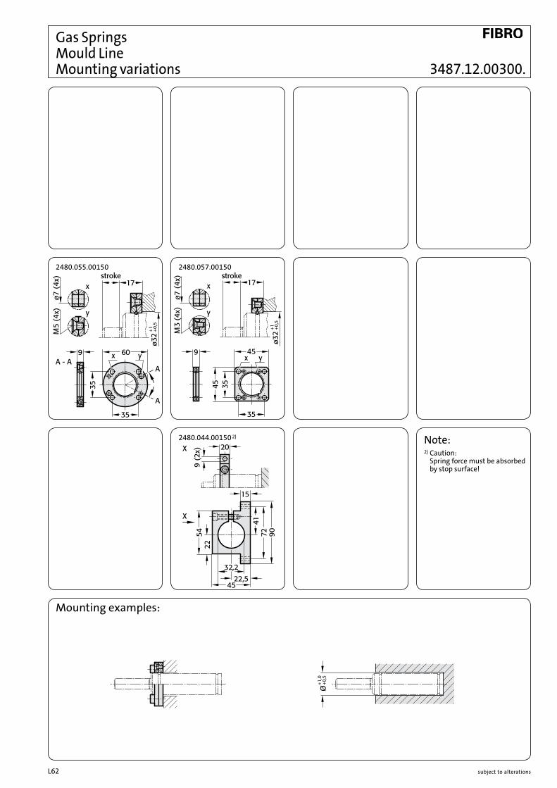
subject to alterationsL62
Gas Springs Mould Line Mounting variations
Mounting examples:
Note:2) Caution:
Spring force must be absorbed by stop surface!
2480.057.00150
2480.044.00150 2)
2480.055.00150
3487.12.00300.
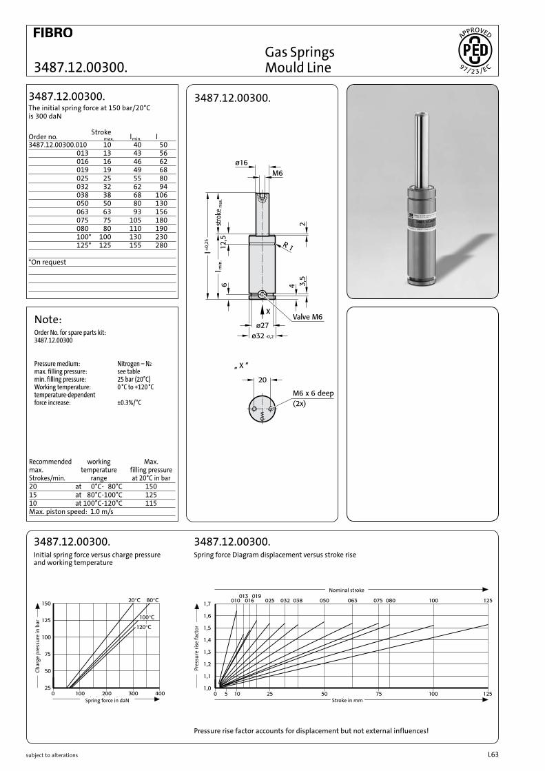
subject to alterations L63
3487.12.00300.
3487.12.00300.
Note:Order No. for spare parts kit: 3487.12.00300
Pressure medium: Nitrogen – N2
max. filling pressure: see table min. filling pressure: 25 bar (20°C) Working temperature: 0 °C to +120 °C temperature-dependent force increase: ±0.3%/°C
Recommended working Max. max. temperature filling pressure Strokes/min. range at 20°C in bar20 at 0°C- 80°C 15015 at 80°C-100°C 12510 at 100°C-120°C 115Max. piston speed: 1.0 m/s
3487.12.00300.Initial spring force versus charge pressure and working temperature
3487.12.00300.Spring force Diagram displacement versus stroke rise
Spring force in daN
Pres
sure
rise
fact
or
Nominal stroke
Stroke in mm
Pressure rise factor accounts for displacement but not external influences!
3487.12.00300.010 10 40 50 013 13 43 56 016 16 46 62 019 19 49 68 025 25 55 80 032 32 62 94 038 38 68 106 050 50 80 130 063 63 93 156 075 75 105 180 080 80 110 190 100* 100 130 230 125* 125 155 280 *On request
3487.12.00300.The initial spring force at 150 bar/20°C is 300 daN
StrokeOrder no. max. lmin. l
Char
ge p
ress
ure
in b
ar
Gas Springs Mould Line

subject to alterationsL64
Gas Springs Mould Line Mounting variations
Note:2) Caution:
Spring force must be absorbed by stop surface!
2480.055.00250 2480.057.00250
2480.044.00250 2)
3487.12.00500.

subject to alterations L65subject to alterations
3487.12.00500.
3487.12.00500.
Note:Order No. for spare parts kit: 3487.12.00500
Pressure medium: Nitrogen – N2
max. filling pressure: see table min. filling pressure: 25 bar (20°C) Working temperature: 0 °C to +120 °C temperature-dependent force increase: ±0.3%/°C
Recommended working Max. max. temperature filling pressure Strokes/min. range at 20°C in bar20 at 0°C- 80°C 15015 at 80°C-100°C 12510 at 100°C-120°C 115Max. piston speed: 1.0 m/s
3487.12.00500.Initial spring force versus charge pressure and working temperature
3487.12.00500.Spring force Diagram displacement versus stroke rise
Spring force in daN
Pres
sure
rise
fact
or
Nominal stroke
Stroke in mm
Pressure rise factor accounts for displacement but not external influences!
3487.12.00500.010 10 40 50 013 13 43 56 016 16 46 62 019 19 49 68 025 25 55 80 032 32 62 94 038 38 68 106 050 50 80 130 063 63 93 156 075 75 105 180 080 80 110 190 100* 100 130 230 125* 125 155 280 *On request
3487.12.00500.The initial spring force at 150 bar/20°C is 500 daN
StrokeOrder no. max. lmin. l
Char
ge p
ress
ure
in b
ar
Gas Springs Mould Line

subject to alterationsL66
Gas Springs Mould Line Mounting variations
DIN
��
-
����.���.�����.�
��
��
��
��
��
ø�
� (
�x
)
M�
� (
�x
)
��
��
��
Km
� (
�x
)
Note:2) Caution:
Spring force must be absorbed by stop surface!
2480.011.00500 2480.011.00500.1
2480.055.00500 2480.057.00500
2480.044.00500 2)
3487.12.00750.

subject to alterations L67
3487.12.00750.
3487.12.00750.
Note:Order No. for spare parts kit: 3487.12.00750
Pressure medium: Nitrogen – N2
max. filling pressure: see table min. filling pressure: 25 bar (20°C) Working temperature: 0 °C to +120 °C temperature-dependent force increase: ±0.3%/°C
Recommended working Max. max. temperature filling pressure Strokes/min. range at 20°C in bar20 at 0°C- 80°C 15015 at 80°C-100°C 12510 at 100°C-120°C 115Max. piston speed: 1.0 m/s
3487.12.00750.Initial spring force versus charge pressure and working temperature
3487.12.00750.Spring force Diagram displacement versus stroke rise
Spring force in daN
Pres
sure
rise
fact
or
Nominal stroke
Stroke in mm
Pressure rise factor accounts for displacement but not external influences!
3487.12.00750.010 10 42 52 013 13 45 58 016 16 48 62 019 19 51 70 025 25 57 82 032 32 64 96 038 38 70 108 050 50 82 132 063 63 95 158 075 75 107 182 080 80 112 192 100* 100 132 232 125* 125 157 282 *On request
3487.12.00750.The initial spring force at 150 bar/20°C is 750 daN
StrokeOrder no. max. lmin. l
Char
ge p
ress
ure
in b
ar
Gas Springs Mould Line

subject to alterationsL68
Gas Springs Mould Line Mounting variations
DIN
74 -
2480.011.00750.3
20ø15
(2x)
M10
(2x)
12
20
12
Km 8
(4x)
75 56,5
7556,5
Note:2) Caution:
Spring force must be absorbed by stop surface!
4) Square collar flange, anti-twist, fixing forcollar connection.
5) Socket head screws withinternal hex (recommended: with low head).
2480.047.00750 2)
2480.044.00750 2)2480.064.00750 4) 2480.045.00750 2)
2480.055.00750 2480.057.00750
2480.011.00750 2480.011.00750.1
3487.12.01000.
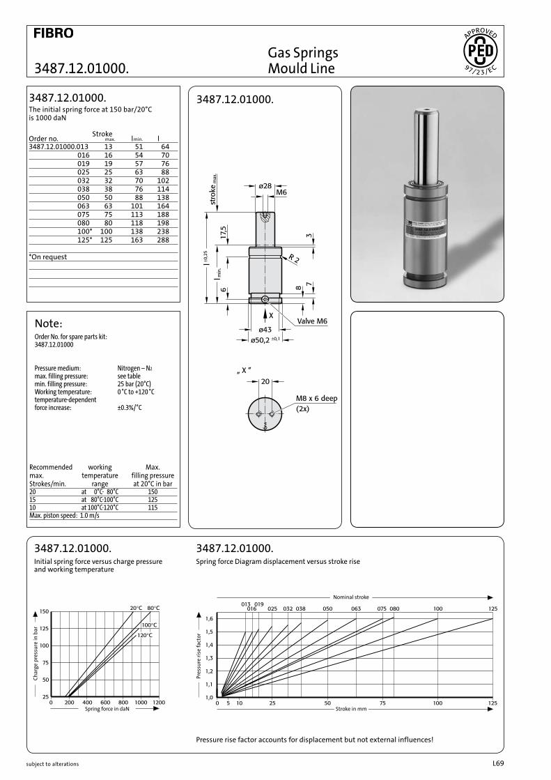
subject to alterations L69
3487.12.01000.
3487.12.01000.
Note:Order No. for spare parts kit: 3487.12.01000
Pressure medium: Nitrogen – N2
max. filling pressure: see table min. filling pressure: 25 bar (20°C) Working temperature: 0 °C to +120 °C temperature-dependent force increase: ±0.3%/°C
Recommended working Max. max. temperature filling pressure Strokes/min. range at 20°C in bar20 at 0°C- 80°C 15015 at 80°C-100°C 12510 at 100°C-120°C 115Max. piston speed: 1.0 m/s
3487.12.01000.Initial spring force versus charge pressure and working temperature
3487.12.01000.Spring force Diagram displacement versus stroke rise
Spring force in daN
Pres
sure
rise
fact
or
Nominal stroke
Stroke in mm
Pressure rise factor accounts for displacement but not external influences!
3487.12.01000.013 13 51 64 016 16 54 70 019 19 57 76 025 25 63 88 032 32 70 102 038 38 76 114 050 50 88 138 063 63 101 164 075 75 113 188 080 80 118 198 100* 100 138 238 125* 125 163 288 *On request
3487.12.01000.The initial spring force at 150 bar/20°C is 1000 daN
StrokeOrder no. max. lmin. l
Char
ge p
ress
ure
in b
ar
Gas Springs Mould Line

subject to alterationsL70
Gas Spring Accessoriessee Registry F:
Gas Spring Accessories

subject to alterations L71
Auxiliary Equipmentsee Registry H:
Chemical Tooling Aidsand Registry J:
Peripheral Equipment

subject to alterationsL72


