A Fancy Digital Clock: Project Design
Ridwan Sami Alex Bell Geoff Young
May 14, 2010
Abstract
This document presents the design of a fancy digital clock with some hardware-accelerated graphics effects. The
output is a VGA monitor. The device is similar to a digital picture frame (such as the ones that display pictures
from SD cards) but also displays the time, date, and day-of-week using anti-aliased tiles in the left half of the screen.
The text animation mimics an old flip clock. The device displays a random sequence of scrolling images to the right
half of the screen. First, we present a broad overview of the device. Then we provide details about the individual
components.
Contents
1 Introduction 1
2 Implementation 1
2.1 VGA controller . . . . . . . . . . . . . . 1
2.1.1 Layers . . . . . . . . . . . . . . . 3
2.1.2 SRAM layout . . . . . . . . . . . 3
2.1.3 Tiles . . . . . . . . . . . . . . . . 3
2.1.4 Blending . . . . . . . . . . . . . . 3
2.1.5 Tile shading and tinting . . . . . 4
2.1.6 Hardware/software interface . . . 4
2.1.7 Command submission . . . . . . . 4
2.2 Background generation . . . . . . . . . . 6
2.2.1 Background dimming . . . . . . . 6
2.3 SDRAM controller . . . . . . . . . . . . 6
2.4 Time keeper . . . . . . . . . . . . . . . . 6
2.4.1 Setting the time . . . . . . . . . 6
2.5 Pseudo-random number generator . . . . 8
3 Division of work 8
4 Lessons learned 8
A Code 9
A.1 fdc top.vhd . . . . . . . . . . . . . . . . 9
A.2 fdc video.vhd . . . . . . . . . . . . . . . 12
A.3 timer.vhd . . . . . . . . . . . . . . . . . 26
A.4 main.c . . . . . . . . . . . . . . . . . . . 28
A.5 qp.cpp . . . . . . . . . . . . . . . . . . . 40
A.6 toarray.py . . . . . . . . . . . . . . . . . 42
A.7 PBASIC ADC . . . . . . . . . . . . . . . 43
1 Introduction
This project aims to combine a typical digital photo frame
with a digital clock. The setup comprises a single Altera
DE2 board connected to a computer monitor through the
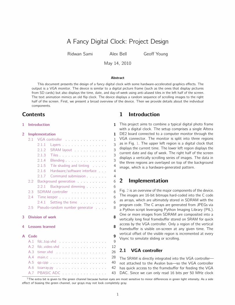
VGA connector. The monitor is split into three regions
as in Fig. 1. The upper left region is a digital clock that
displays the current time. The lower left region displays the
current date and day of week. The right half of the screen
displays a vertically scrolling series of images. The data in
the three regions are overlayed on top of the background
image, which is a hardware-generated pattern.
2 Implementation
Fig. 2 is an overview of the major components of the device.
The images are 16-bit bitmaps hard-coded into the C code
as arrays, which are ultimately stored in SDRAM with the
program code. The C arrays are generated from JPEGs via
a Python script leveraging Python Imaging Library (PIL).
One or more images from SDRAM are composited into a
vertically long final framebuffer stored on SRAM for quick
access by the VGA controller. Only a region of the vertical
framebuffer is visible on-screen at any given time. The
vertical offset of the visible region is incremented at every
Vsync to simulate sliding or scrolling.
2.1 VGA controller
The SRAM is directly integrated into the VGA controller—
not attached to the Avalon bus—so the VGA controller
has quick access to the framebuffer for feeding the VGA
DAC. Since we can only read 16 bits per 50 MHz clock
1The extra bit is given to the green channel because human eyes are most sensitive to minor differences in green light intensity. As a side
effect of biasing the green channel, our grays may not look completely gray.
1

2.1 VGA controller Fancy Digital Clock
08:23:16 PM
04/20/2010
Tuesday
Figure 1: Screen layout
Avalon bus
Image 1
Image 2
...
Program code
Font bitmaps
8MB SDRAM
Tile data
Tile array
Command Q
CPU cache
60KB Block RAM
VGA
peripheralVGA DAC
Framebuffer
512KB SRAM
Time keeper
Push buttons
Nios II
Figure 2: Overview of the components of the device
2
2.1 VGA controller Fancy Digital Clock
cycle and write 16 bits per 2 clock cycles, we use the 16-bit
R5G6B51 pixel format as opposed to the more popular
24-bit true color pixel format (R8G8B8). This simplifies
hardware since the VGA controller can read/write an entire
pixel per SRAM access.
The processor, after fetching data from its SDRAM
image memory and doing computations, tells the VGA pe-
ripheral the color of each pixel in the buffer. The command
from the processor is written into a queue in block RAM
before being committed to SRAM as a way of scheduling
SRAM reads and writes and make sure they don’t interfere
with each other (see sec. 2.1.7). We are only reading from
SRAM when we are painting the right half of the screen so
the queue is emptied and the data is written to the SRAM
while we are painting of the left half of the canvas.
2.1.1 Layers
The screen is composed of three layers with a different
hardware path for each layer:
• The bottom layer is the background layer, which is
algorithmically generated in hardware on-the-fly as
we scan across. See sec. 2.2 on page 6 for a detailed
explanation of the background.
• The text layer takes up the left half of the screen and
includes elements such as the time, date, and images.
Tiles are used for text and numbers. The VGA con-
troller decides which pixels to display based on trans-
parency bits that are stored with the monochrome tile
data. The characters used in the date and time have
4 bits of transparency information so that edges ap-
pear smooth against the background. See sec. 2.1.3
on page 3 for a detailed explanation of the implemen-
tation of tiles.
• The right half of the screen contains images coming
out of a framebuffer with pixels quadrupled so that
we can fill a 320×480 area with images no wider than
144 pixels. This decision is because of the limited
size of SRAM. A predetermined color—such as bright
purple—was designated a see-through pixel so that
when the hardware encounters a pixel of this color, it
just sends the background color to VGA DAC. This
is similar to chroma keying used in video production
and hardware overlays in old computer video drivers.
Since images are confined to the right half and text
is confined to the left half, the text layer never intersects
with the framebuffer layer. But both the text layer and the
image layer interacts with the background layer because of
the presence of transparent regions in both of those upper
layers.
2.1.2 SRAM layout
The SRAM holds a single 256× 1024 buffer of 16-bit color
information. Only a 160× 240 region is visible at a given
time and the pixels are quadrupled to fit the 320 × 480
right half of the screen. The rightmost pixels in the image
buffer are never be visible but exist only so that the width
of the rows is a power of 2, which simplifies the logic in
seeking to the start of a row.
We had the option of storing tile pixel data in the re-
gions of SRAM which are never be visible but for the sake
of code simplicity, the pixel tile data is stored in block RAM.
2.1.3 Tiles
Tile size and bit depth were chosen by the availability of
block RAM. Although using either block RAM or SRAM
would be roughly equivalent (either option requires a two-
cycle write and single-cycle read operation), we selected
block RAM because it would be easier to organize since
SRAM is partially filled by the image buffer (it is not en-
tirely filled because only the leftmost 160 pixels are ever
visible in each 256-pixel row). We selected tiles that are
32 × 32 pixels and have a 4-bit depth. They are packed
into 16-bit sets of four adjacent pixels. With 72 tiles (see
sec. A.5 on page 40 for which 72 tiles we used), we used
up 32× 32× 4× 72 = 294912 bits, which is a significant
chunk of the available 483840 bits on block RAM on the
EP2C35.
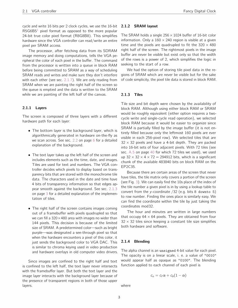
Because there are certain areas of the screen that never
have tiles, the tile matrix only covers a portion of the screen
(see Fig. 3). We can easily find the 10s place of the index of
the tile number a given pixel is in by using a lookup table to
convert from the y -coordinate /32 (e.g. bits 8 downto 5)
to row number. Finding the ones place is similarly easy. We
can find the coordinate within the tile by just taking the
coordinates mod32.
The hour and minutes are written in large numbers
that occupy 64× 64 pixels. They are obtained from four
32 × 32 tiles since keeping a constant tile size simplifies
both hardware and software.
2.1.4 Blending
The alpha channel is an unsigned 4-bit value for each pixel.
The opacity is on a linear scale, i. e. a value of ”0010”
would appear half as opaque as ”0100”. The blending
function applied to each channel of each pixel is
co = cf α+ cb(1− α)
where
3
2.1 VGA controller Fancy Digital Clock
0 1 2 3 4 5 6 7 8 9
10 11 12 13 14 15 16 17 18 19
20 21 22 23 24 25 26 27 28 29
30 31 32 33 34 35 36 37 38 39
40 41 42 43 44 45 46 47 48 49
MM:HH in large text
SS and AM/PM
MM/DD/YYYY
Day of week
Figure 3: Tile layout—the numbers in the square indicate the index of the array holding tile identification information.
All the the text outside the boxes are informational and do not appear on the screen.
co is the final unsigned channel value sent to
the VGA DAC
cf is the unsigned value of the current chan-
nel of the foreground
cb is the unsigned value of the current chan-
nel of the background
α is the unsigned alpha value ranging from
”0000” to ”1111”
1 is the unsigned value ”1111”.
cf and cb are 9-bit values so they fit into the 9-bit multipli-
ers available on the board. Since the product is more than
10 bits, to normalize it to the 10-bit range accepted by the
VGA DAC, we simply take the 10 most significant bits. This
also enables us to avoid using floating-point multiplication.
Because the alpha channel is 4 bits, the foreground is
9 bits, and we’re only keeping the highest 10 bits instead
of normalizing it by division, there is significant round-off
error that is most visible in the completely transparent
parts of the tile which causes it to appear slightly darker
than the background outside tiled areas. To alleviate this,
we have an if statement that simply shows through to the
background and bypasses blending when the alpha channel
of the current pixel is ”0000”. The round-off error in the
non-transparent pixels is visually undetectable.
There was a discussion of storing an alpha channel that
determines how many spaces to bit shift the foreground
so that we’d avoid multiplication, which generates a lot
more hardware than shifting. However, there we couldn’t
come up with an adequate blending function that blends
two layers and uses multiplications by powers of 2 only
(the factor of 1 − α makes this difficult in the blending
function above). This would be trivially possible only if our
background was uniformly black.
2.1.5 Tile shading and tinting
Our first implementation had solid-colored tiles by assuming
that the foreground color at every pixel was always white
(an unsigned value of ”111111111” for each channel). By
instead using a different hard-coded set of R, G, and B
values as the foreground color, a tile becomes tinted.
To simulate shading, the foreground color is gradually
varied from the top the bottom of a tile. For simplicity,
we simply subtracted the current y -coordinate within the
current tile from bits 7 downto 3 of the foreground color
for each channel so that the foreground before gradually
darker at lower rows. Large tiles have a subtly different
shading method.
2.1.6 Hardware/software interface
We use the address port as a command code (and a
16-bit writedata port as data) to request one of many
operations or commands detailed in Table 1 on page 5.
The only data we need to read from the VGA peripheral
is the vertical offset integer that determines what portion
of the image buffer is visible. Using this information, we
can make sure we only paint parts of the SRAM that are
not currently off-screen.
2.1.7 Command submission
When a command is sent by the software, it is placed on a
ring buffer before being executed by the hardware. There
are two pointers in the SRAM which point to the front
4

2.1 VGA controller Fancy Digital Clock
Command Value Description
OP˙WRITE 0x00 This command is used while drawing the framebuffer. The 16-bit value writedata is
placed into the current position in SRAM and is thus the R5G6B5 data corresponding
to the current pixel the write pointer is pointing to. The pointer is incremented so that
a subsequent call to this command will draw the next pixel.
OP˙SET˙VERT˙OFFSET 0x01 The highest 10 bits of writedata are placed into the pointer that determines which
row in the 1024-row SRAM space is the row that is visible at the absolute top of the
screen.
OP˙SEEK˙ROW 0x04 This command is used while drawing the framebuffer. The highest 10 bits of writedata
are placed into the pointer that determines which row in the 1024-row SRAM space
we are now writing to (i. e. where will the next OP˙WRITE write to). The column is also
set to 0 so we start writing at the start of the line.
OP˙TILE˙SET˙CURRENT 0x05 This command is used while setting up the pixel data in the tiles. The highest 7 bits of
writedata are placed into the pointer that determines which of the 72 slots for tile
pixel data our subsequent OP˙TILE˙SEEK and OP˙TILE˙WRITE will refer to.
OP˙TILE˙WRITE 0x06 This command is used while setting up the pixel data in the tiles. Take the 16-bits
in writedata and copy them into block RAM at the position specified by the pointer
pointing to which tile we’re setting up and the pointer pointing to which set of 4 pixels
in this tile we’re setting up. The 16 bits will eventually be interpreted as four pixels,
each with a 4-bit alpha channel. The pointer is incremented so a subsequent call to
this command will draw in the next set of four pixels.
OP˙TILE˙SEEK 0x07 This command is used while setting up the pixel data in the tiles. The highest 8
bits from writedata are placed into the pointer pointing to where the next call to
OP˙TILE˙WRITE will draw to.
OP˙TILE˙TO˙CHANGE 0x08 This command is used while populating the tile matrix with tiles. The highest 6 bits are
copied to the pointer that determines which position in the tile matrix we’ll be setting
up (the numbers referred to here are explain in Fig. 3 on page 4).
OP˙TILE˙CHANGE˙TO 0x0A This command is used while populating the tile matrix with tiles. After choosing a
position in the tile matrix using OP˙TILE˙TO˙CHANGE, this command takes the highest
7 bits from writedata and shows that tile in the selected position. Valid values of
writedata are unsigned values between 0 and 71 inclusive. The tile that each number
refers to is set up via preprocessor #defines in the C code such as #define TILE˙W 24.
OP˙TILE˙SET˙ANIM˙STATE 0x0B Takes the highest 4-bits from writedata and copies that to the 4 animation state bits
corresponding to the current tile position in the tile matrix. A value of 0x0 makes the
tile invisible, a value of 0x1 makes the tile unanimated, and values between 0x2 and
0xF inclusive refer to the 14 frames during a tile’s animation. States 0x3 through 0xF
inclusive are set and used internally by hardware. To initiate the animation of a tile, the
software needs to set up the next tile using OP˙TILE˙TRANS˙CHANGE and then calling
OP˙TILE˙SET˙ANIM˙STATE with a writedata value of 0x2.
OP˙TINT 0x0C The highest bit of writedata determines whether the tile in the current position set
by OP˙TILE˙TO˙CHANGE is tinted green.
OP˙TILE˙TRANS˙CHANGE 0x0D This command is like OP˙TILE˙CHANGE˙TO except it sets what the next tile will be after
the animation runs through.
Table 1: Commands
5

2.2 Background generation Fancy Digital Clock
of the queue and the back queue. When a command is
submitted, it is put on the front of the queue and the front
pointer is incremented. When a command is committed or
executed from the queue, the back pointer is incremented.
When the front pointer and back pointer point to the same
element, there are no commands in the queue waiting to be
committed. The queue can store 31 commands although
we may reduce the size if we find that we are never queuing
more a certain number of commands. The queue pointers
wrap around so it acts as a ring buffer.
Commands that do not deal with the SRAM could the-
oretically bypass the queue but we put them on the queue
for consistency and to simplify hardware logic. We incur
an small delay during certain operations that do not touch
SRAM but it is insignificant.
One danger to be catious of is that if our software is
too fast, it may overflow the ring buffer and each time
the ring buffer overflows, it will discard a full set of 32
commands, which may lead to visual artifacts on the screen.
We haven’t encountered this issue while developing the
project but if we were to notice visual artifacts, we would
artifically slow down the software or increase the size of
the ring buffer.
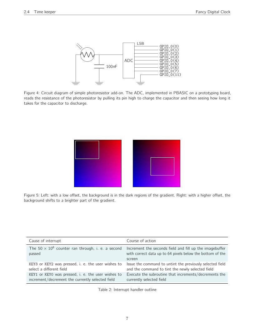
2.2 Background generation
Since we don’t have enough memory left over to store an
image as a background, we decided to have background
with pixel colors generated as a simple function of the
x- and y -coordinates of the current pixel. For each pixel,
we simply use the x-coordinate plus a numerical offset as
the R channel, the y -coordinate plus a numerical offset as
the B channel, and ”0000000000” as the G channel. This
creates a gradient that’s darkest at the top-left corner,
reddest at the bottom-left, bluest at the top-right, and
purplest at the bottom-right. The numerical offset comes
from a photoresistor and is used to implement background
dimming.
2.2.1 Background dimming
Since a user would not want the digital clock to be overly
bright at night when the room lights are off—the bright-
ness may disrupt the user’s sleep—and we do not want
the digital clock to be so dim that it is difficult to read
under bright sunlight, we decided to have the background
brightness adjust to environmental conditions.
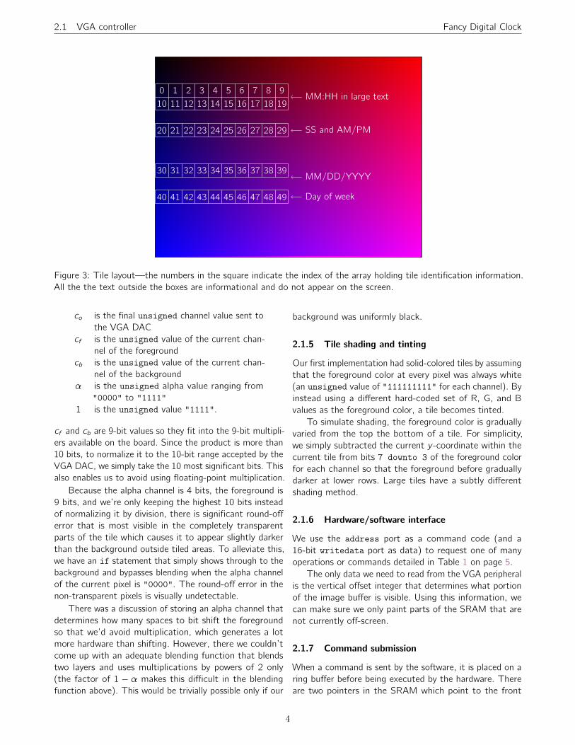
We fed the value of the resistance across a photoresis-
tor into an 8-bit ADC and hooked the ADC output to the
top 8 pins of the general purpose I/O signal GPIO˙0. The
GPIO˙0 ports and hooked directly to the VGA peripheral
(bypassing the Avalon bus). The VGA peripheral treats the
8-bit value it receives as the numerical offset described in
the previous section to both the R and B channels so that
higher values coming into GPIO˙0(7 downto 0) shifts the
visible part of the gradient to brighter regions. This is
illustrated in Fig. 5.
When the photoresistor is not hooked up,
GPIO˙0(7 downto 0) takes on the value ”11111111”
so the digital clock defaults to maximum background
brightness.
2.3 SDRAM controller
The SDRAM holds instructions and data for the processor.
The SDRAM controller is mostly automatically generated
by the SOPC builder. Although SDRAM is an order of
magnitude slower than SRAM, it is not a bottleneck since
we allocateed a generous cache to the processor so con-
secutive localized reads do not incur a large penalty. By
hard-coding bitmap images and fonts into the C code, we
avoid difficulties associated with interfacing with an addi-
tional image source peripheral such as an SD card reader,
which is otherwise outside the scope of this project.
As the first action upon running the program code, the
CPU takes the font tiles from SDRAM and writes them
to block RAM. By having the tiles set up in software, we
always have the option of loading in tiles on the fly in case
we need a new tile set (although we don’t take advantage
of this opportunity in this project). Having tile pixel data
in software is also easier to manage. As the program runs,
images are taken from SDRAM and written row by row
to the SRAM attached to the VGA controller. Interrupts
from the time keeper prompts the CPU to change the tiles
that show the current time.
2.4 Time keeper
This peripheral simply generates an interrupt every 50 mil-
lion clock cycles of the 50 MHz clock to tell the processor
to advance the displayed clock by one second. Upon startup,
the clock displays some hard-coded startup date and time.
By holding the buttons on the board, the user is able to
change the time. Pressing the buttons generates interrupts
that tell the CPU to display different tiles that represent
different numbers.
Accurate time keeping is actually an auxiliary task. Our
primary focus is fancy graphics and the digital clock as-
pect simply gives us an opportunity to use tiles with alpha
channels and makes the device useful.
2.4.1 Setting the time
The user may set up the time using the four push-buttons
on the board. Using buttons KEY3 and KEY2 to highlight
either the hour, minute, day, month, or year. Once a field
has been highlighted, the user may use KEY1 and KEY0 to
either increment or decrement the highlighted field.
6
2.4 Time keeper Fancy Digital Clock
100nF
ADC
LSBGPIO˙0(0)GPIO˙0(1)GPIO˙0(2)GPIO˙0(3)GPIO˙0(4)GPIO˙0(5)GPIO˙0(6)GPIO˙0(7)GPIO˙0(11)
Figure 4: Circuit diagram of simple photoresistor add-on. The ADC, implemented in PBASIC on a prototyping board,
reads the resistance of the photoresistor by pulling its pin high to charge the capacitor and then seeing how long it
takes for the capacitor to discharge.
Figure 5: Left: with a low offset, the background is in the dark regions of the gradient. Right: with a higher offset, the
background shifts to a brighter part of the gradient.
Cause of interrupt Course of action
The 50 × 106 counter ran through, i. e. a second
passed
Increment the seconds field and fill up the imagebuffer
with correct data up to 64 pixels below the bottom of the
screen
KEY3 or KEY2 was pressed, i. e. the user wishes to
select a different field
Issue the command to untint the previously selected field
and the command to tint the newly selected field
KEY1 or KEY0 was pressed, i. e. the user wishes to
increment/decrement the currently selected field
Execute the subroutine that increments/decrements the
currently selected field
Table 2: Interrupt handler outline
7
2.5 Pseudo-random number generator Fancy Digital Clock
Whenever the user presses a button, it is debounced in
hardware. A interrupt is generated and the software decides
what to do using logic outlined in Table 2.
2.5 Pseudo-random number generator
An attempt to randomize the pictures displayed on the
screen was devised by using a pseudo-random number gen-
erator called a linear feedback shift register. The method re-
lies on a chosen seeding value to start the process. Choices
of this number are important. Since this method is only
pseudo-random, the values outputted will eventually cycle
back to the starting value. A good seeding choice will go
through all possible 2n − 1 states, except 0, before return-
ing to its original seeding value. We chose to use a large
unsigned 16-bit value as a seeding value. The output was
then modded with the number of pictures we wished to
display so that only numbers in the desired range were
produced.
3 Division of work
Ridwan:
• Initial VHDL code to accept 16-bit data from soft-
ware and write into SRAM and then display contents
of SRAM on screen.
• Ring buffer to queue commands before executing
• Hardware-software interface architecture and plan-
ning
• Python script to resize and convert images to C
arrays (see sec. A.6 on page 42)
• Qt program to generate tile bitmaps (see sec. A.5
on page 40)
• Code to place tiles on the VGA raster with blending
and shading
• Final report in LATEX
Alex:
• Subroutines to draw and update fields such as hour
and minute from software
• Timer module
• Portion of interrupt handler that checks whether user
is setting the time
• Animation hardware in VHDL
• C code cleanup and modularization
Geoff:
• Calculation of VHDL arrays containing row lookup
tables for tile changing animation
• VHDL code for tile flipping animation
• Simulating an ADC on a prototyping board
• Pseudo-random number generator (see sec. 2.5 on
page 8)
• Subroutine for randomizing pictures
• Debugging and Optimization of time-keeping and
button logic
• C code cleanup and modularization
4 Lessons learned
These lessons should also be considered advice for future
students.
• Don’t be too ambitious when deciding on a project
proposal or decide on a project that encompasses a
wide range of areas; select one area of interest on
focus on it.
• Don’t think you can simply re-use someone else’s
code and have it work immediately and effortlessly—
getting it to work with your existing code is difficult
and you might encounter errors in the external code
that were only exposed by integrating it into your
code.
• Remember to set SRAM data pins to tri-state mode
when you’re done writing.
• Don’t assume all members of the team have to be
present to work on the project—there are times when
work cannot be parallelized and one member may
have to come in and work alone. Don’t waste time by
having the other members present for moral support.
• Keep regular backups of your source code (or use a
source control system) and do go over your account
quote because your files may be truncated when you
save.
• Use the block RAM inference template to make sure
large arrays go into block RAM instead of generating
hundreds or thousands of flip-flops or registers.
• Don’t use square tiles for text. Monospace fonts usu-
ally do not have square characters—they are taller
than they are wide.
8
A. Code Fancy Digital Clock
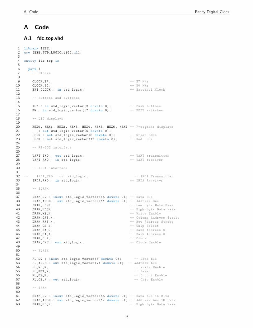
A Code
A.1 fdc top.vhd
1 library IEEE;
2 use IEEE.STD˙LOGIC˙1164.all;
3
4 entity fdc˙top is
5
6 port (
7 -- Clocks
8
9 CLOCK˙27 , -- 27 MHz
10 CLOCK˙50 , -- 50 MHz
11 EXT˙CLOCK : in std˙logic; -- External Clock
12
13 -- Buttons and switches
14
15 KEY : in std˙logic˙vector (3 downto 0); -- Push buttons
16 SW : in std˙logic˙vector (17 downto 0); -- DPDT switches
17
18 -- LED displays
19
20 HEX0 , HEX1 , HEX2 , HEX3 , HEX4 , HEX5 , HEX6 , HEX7 -- 7-segment displays
21 : out std˙logic˙vector (6 downto 0);
22 LEDG : out std˙logic˙vector (8 downto 0); -- Green LEDs
23 LEDR : out std˙logic˙vector (17 downto 0); -- Red LEDs
24
25 -- RS -232 interface
26
27 UART˙TXD : out std˙logic; -- UART transmitter
28 UART˙RXD : in std˙logic; -- UART receiver
29
30 -- IRDA interface
31
32 -- IRDA˙TXD : out std˙logic; -- IRDA Transmitter
33 IRDA˙RXD : in std˙logic; -- IRDA Receiver
34
35 -- SDRAM
36
37 DRAM˙DQ : inout std˙logic˙vector (15 downto 0); -- Data Bus
38 DRAM˙ADDR : out std˙logic˙vector (11 downto 0); -- Address Bus
39 DRAM˙LDQM , -- Low -byte Data Mask
40 DRAM˙UDQM , -- High -byte Data Mask
41 DRAM˙WE˙N , -- Write Enable
42 DRAM˙CAS˙N , -- Column Address Strobe
43 DRAM˙RAS˙N , -- Row Address Strobe
44 DRAM˙CS˙N , -- Chip Select
45 DRAM˙BA˙0 , -- Bank Address 0
46 DRAM˙BA˙1 , -- Bank Address 0
47 DRAM˙CLK , -- Clock
48 DRAM˙CKE : out std˙logic; -- Clock Enable
49
50 -- FLASH
51
52 FL˙DQ : inout std˙logic˙vector (7 downto 0); -- Data bus
53 FL˙ADDR : out std˙logic˙vector (21 downto 0); -- Address bus
54 FL˙WE˙N , -- Write Enable
55 FL˙RST˙N , -- Reset
56 FL˙OE˙N , -- Output Enable
57 FL˙CE˙N : out std˙logic; -- Chip Enable
58
59 -- SRAM
60
61 SRAM˙DQ : inout std˙logic˙vector (15 downto 0); -- Data bus 16 Bits
62 SRAM˙ADDR : out std˙logic˙vector (17 downto 0); -- Address bus 18 Bits
63 SRAM˙UB˙N , -- High -byte Data Mask
9

A.1 fdc top.vhd Fancy Digital Clock
64 SRAM˙LB˙N , -- Low -byte Data Mask
65 SRAM˙WE˙N , -- Write Enable
66 SRAM˙CE˙N , -- Chip Enable
67 SRAM˙OE˙N : out std˙logic; -- Output Enable
68
69 -- USB controller
70
71 OTG˙DATA : inout std˙logic˙vector (15 downto 0); -- Data bus
72 OTG˙ADDR : out std˙logic˙vector (1 downto 0); -- Address
73 OTG˙CS˙N , -- Chip Select
74 OTG˙RD˙N , -- Write
75 OTG˙WR˙N , -- Read
76 OTG˙RST˙N , -- Reset
77 OTG˙FSPEED , -- USB Full Speed , 0 = Enable , Z = Disable
78 OTG˙LSPEED : out std˙logic; -- USB Low Speed , 0 = Enable , Z = Disable
79 OTG˙INT0 , -- Interrupt 0
80 OTG˙INT1 , -- Interrupt 1
81 OTG˙DREQ0 , -- DMA Request 0
82 OTG˙DREQ1 : in std˙logic; -- DMA Request 1
83 OTG˙DACK0˙N , -- DMA Acknowledge 0
84 OTG˙DACK1˙N : out std˙logic; -- DMA Acknowledge 1
85
86 -- 16 X 2 LCD Module
87
88 LCD˙ON , -- Power ON/OFF
89 LCD˙BLON , -- Back Light ON/OFF
90 LCD˙RW , -- Read/Write Select , 0 = Write , 1 = Read
91 LCD˙EN , -- Enable
92 LCD˙RS : out std˙logic; -- Command/Data Select , 0 = Command , 1 = Data
93 LCD˙DATA : inout std˙logic˙vector (7 downto 0); -- Data bus 8 bits
94
95 -- SD card interface
96
97 SD˙DAT , -- SD Card Data
98 SD˙DAT3 , -- SD Card Data 3
99 SD˙CMD : inout std˙logic; -- SD Card Command Signal
100 SD˙CLK : out std˙logic; -- SD Card Clock
101
102 -- USB JTAG link
103
104 TDI , -- CPLD -¿ FPGA (data in)
105 TCK , -- CPLD -¿ FPGA (clk)
106 TCS : in std˙logic; -- CPLD -¿ FPGA (CS)
107 TDO : out std˙logic; -- FPGA -¿ CPLD (data out)
108
109 -- I2C bus
110
111 I2C˙SDAT : inout std˙logic; -- I2C Data
112 I2C˙SCLK : out std˙logic; -- I2C Clock
113
114 -- PS/2 port
115
116 PS2˙DAT , -- Data
117 PS2˙CLK : in std˙logic; -- Clock
118
119 -- VGA output
120
121 VGA˙CLK , -- Clock
122 VGA˙HS , -- H˙SYNC
123 VGA˙VS , -- V˙SYNC
124 VGA˙BLANK , -- BLANK
125 VGA˙SYNC : out std˙logic; -- SYNC
126 VGA˙R , -- Red [9:0]
127 VGA˙G , -- Green [9:0]
128 VGA˙B : out std˙logic˙vector (9 downto 0); -- Blue [9:0]
129
130 -- Ethernet Interface
10

A.1 fdc top.vhd Fancy Digital Clock
131
132 ENET˙DATA : inout std˙logic˙vector (15 downto 0); -- DATA bus 16Bits
133 ENET˙CMD , -- Command/Data Select , 0 = Command , 1 = Data
134 ENET˙CS˙N , -- Chip Select
135 ENET˙WR˙N , -- Write
136 ENET˙RD˙N , -- Read
137 ENET˙RST˙N , -- Reset
138 ENET˙CLK : out std˙logic; -- Clock 25 MHz
139 ENET˙INT : in std˙logic; -- Interrupt
140
141 -- Audio CODEC
142
143 AUD˙ADCLRCK : inout std˙logic; -- ADC LR Clock
144 AUD˙ADCDAT : in std˙logic; -- ADC Data
145 AUD˙DACLRCK : inout std˙logic; -- DAC LR Clock
146 AUD˙DACDAT : out std˙logic; -- DAC Data
147 AUD˙BCLK : inout std˙logic; -- Bit -Stream Clock
148 AUD˙XCK : out std˙logic; -- Chip Clock
149
150 -- Video Decoder
151
152 TD˙DATA : in std˙logic˙vector (7 downto 0); -- Data bus 8 bits
153 TD˙HS , -- H˙SYNC
154 TD˙VS : in std˙logic; -- V˙SYNC
155 TD˙RESET : out std˙logic; -- Reset
156
157 -- General -purpose I/O
158
159 GPIO˙0 , -- GPIO Connection 0
160 GPIO˙1 : inout std˙logic˙vector (35 downto 0) -- GPIO Connection 1
161 );
162
163 end fdc˙top;
164
165 architecture rtl of fdc˙top is
166
167 COMPONENT sdram˙pll
168 PORT (
169 inclk0 : IN STD˙LOGIC;
170 c0 : OUT STD˙LOGIC;
171 c1 : OUT STD˙LOGIC
172 );
173 END COMPONENT;
174
175 signal pll˙c1 : std˙logic := ’0’;
176
177 begin
178
179 V1: entity work.fdc port map (
180 clk =¿ pll˙c1 ,
181 reset˙n =¿ ’1’,
182
183 VGA˙CLK˙from˙the˙vga =¿ VGA˙CLK ,
184 VGA˙HS˙from˙the˙vga =¿ VGA˙HS ,
185 VGA˙VS˙from˙the˙vga =¿ VGA˙VS ,
186 VGA˙BLANK˙from˙the˙vga =¿ VGA˙BLANK ,
187 VGA˙SYNC˙from˙the˙vga =¿ VGA˙SYNC ,
188 VGA˙R˙from˙the˙vga =¿ VGA˙R ,
189 VGA˙G˙from˙the˙vga =¿ VGA˙G ,
190 VGA˙B˙from˙the˙vga =¿ VGA˙B ,
191 SRAM˙ADDR˙from˙the˙vga =¿ SRAM˙ADDR ,
192 SRAM˙CE˙N˙from˙the˙vga =¿ SRAM˙CE˙N ,
193 SRAM˙DQ˙to˙and˙from˙the˙vga =¿ SRAM˙DQ ,
194 SRAM˙LB˙N˙from˙the˙vga =¿ SRAM˙LB˙N ,
195 SRAM˙OE˙N˙from˙the˙vga =¿ SRAM˙OE˙N ,
196 SRAM˙UB˙N˙from˙the˙vga =¿ SRAM˙UB˙N ,
197 SRAM˙WE˙N˙from˙the˙vga =¿ SRAM˙WE˙N ,
11

A.2 fdc video.vhd Fancy Digital Clock
198
199 zs˙dq˙to˙and˙from˙the˙sdram =¿ DRAM˙DQ ,
200 zs˙addr˙from˙the˙sdram =¿ DRAM˙ADDR ,
201 zs˙dqm˙from˙the˙sdram (0) =¿ DRAM˙LDQM ,
202 zs˙dqm˙from˙the˙sdram (1) =¿ DRAM˙UDQM ,
203 zs˙we˙n˙from˙the˙sdram =¿ DRAM˙WE˙N ,
204 zs˙cas˙n˙from˙the˙sdram =¿ DRAM˙CAS˙N ,
205 zs˙ras˙n˙from˙the˙sdram =¿ DRAM˙RAS˙N ,
206 zs˙cs˙n˙from˙the˙sdram =¿ DRAM˙CS˙N ,
207 zs˙ba˙from˙the˙sdram (0) =¿ DRAM˙BA˙0 ,
208 zs˙ba˙from˙the˙sdram (1) =¿ DRAM˙BA˙1 ,
209 zs˙cke˙from˙the˙sdram =¿ DRAM˙CKE ,
210
211 key˙to˙the˙TimerModule =¿ KEY ,
212 -- LEDR˙from˙the˙TimerModule =¿ LEDR ,
213
214 LEDR˙from˙the˙vga =¿ LEDR ,
215 GPIO˙0˙to˙the˙vga =¿ GPIO˙0
216 );
217
218 neg˙3ns: sdram˙pll PORT MAP (CLOCK˙50 , DRAM˙CLK , pll˙c1);
219
220 HEX7 ¡= ”0001001”; -- Leftmost
221 HEX6 ¡= ”0000110”;
222 HEX5 ¡= ”1000111”;
223 HEX4 ¡= ”1000111”;
224 HEX3 ¡= ”1000000”;
225 HEX2 ¡= (others =¿ ’1’);
226 HEX1 ¡= (others =¿ ’1’);
227 HEX0 ¡= (others =¿ ’1’); -- Rightmost
228 -- LEDG ¡= (others =¿ ’1’);
229 -- LEDR ¡= (others =¿ ’1’);
230 LCD˙ON ¡= ’1’;
231 LCD˙BLON ¡= ’1’;
232
233 -- Set all bidirectional ports to tri -state
234 FL˙DQ ¡= (others =¿ ’Z’);
235 OTG˙DATA ¡= (others =¿ ’Z’);
236 LCD˙DATA ¡= (others =¿ ’Z’);
237 SD˙DAT ¡= ’Z’;
238 I2C˙SDAT ¡= ’Z’;
239 ENET˙DATA ¡= (others =¿ ’Z’);
240 AUD˙ADCLRCK ¡= ’Z’;
241 AUD˙DACLRCK ¡= ’Z’;
242 AUD˙BCLK ¡= ’Z’;
243 GPIO˙0 ¡= (others =¿ ’Z’);
244 GPIO˙1 ¡= (others =¿ ’Z’);
245
246 end rtl;
A.2 fdc video.vhd
1 library ieee;
2 use ieee.std˙logic˙1164.all;
3 use ieee.numeric˙std.all;
4
5 entity fdc˙video is
6 port (
7 reset : in std˙logic;
8 clk : in std˙logic; -- 50 MHz
9
10 read : in std˙logic;
11 write : in std˙logic;
12 chipselect : in std˙logic;
13 address : in unsigned (4 downto 0);
14 readdata : out unsigned (15 downto 0);
12

A.2 fdc video.vhd Fancy Digital Clock
15 writedata : in unsigned (15 downto 0);
16
17 VGA˙CLK , -- Clock
18 VGA˙HS , -- H˙SYNC
19 VGA˙VS , -- V˙SYNC
20 VGA˙BLANK , -- BLANK
21 VGA˙SYNC : out std˙logic; -- SYNC
22 VGA˙R , -- Red [9:0]
23 VGA˙G , -- Green [9:0]
24 VGA˙B : out std˙logic˙vector (9 downto 0); -- Blue [9:0]
25
26 LEDR : out std˙logic˙vector (17 downto 0);
27 LEDG : out std˙logic˙vector (8 downto 0);
28
29 GPIO˙0 : in std˙logic˙vector (35 downto 0);
30
31 -- Control Singals for SRAM
32 SRAM˙DQ : inout std˙logic˙vector (15 downto 0);
33 SRAM˙ADDR : out std˙logic˙vector (17 downto 0);
34 SRAM˙UB˙N ,
35 SRAM˙LB˙N ,
36 SRAM˙WE˙N ,
37 SRAM˙CE˙N ,
38 SRAM˙OE˙N : out std˙logic
39 );
40 end fdc˙video;
41
42 architecture rtl of fdc˙video is
43
44 COMPONENT TilesRam PORT (
45 clk : in std˙logic;
46 we : in std˙logic;
47 a : in unsigned (14 downto 0);
48 di : in unsigned (15 downto 0);
49 do : out unsigned (15 downto 0)
50 );
51 END COMPONENT;
52
53 COMPONENT counter
54 port(
55 Clk , Reset: in std˙logic;
56 Q: out integer
57 );
58 end COMPONENT;
59 -- Video parameters
60
61 constant HTOTAL : integer := 800;
62 constant HSYNC : integer := 96;
63 constant HBACK˙PORCH : integer := 48;
64 constant HACTIVE : integer := 640;
65 constant HFRONT˙PORCH : integer := 16;
66
67 constant VTOTAL : integer := 525;
68 constant VSYNC : integer := 2;
69 constant VBACK˙PORCH : integer := 33;
70 constant VACTIVE : integer := 480;
71 constant VFRONT˙PORCH : integer := 10;
72
73 -- Opcodes
74
75 -- Write a 16-bit R5G6B5 pixel to where the pixel counter is pointing in SRAM
76 constant OP˙WRITE : unsigned := ”00000”;
77
78 -- Which part of the 1024-row space should we start showing?
79 constant OP˙SET˙VERT˙OFFSET : unsigned := ”00001”;
80
81 -- Change pixel counter to the specified row in the 1024-row space
13
A.2 fdc video.vhd Fancy Digital Clock
82 -- Should also sets the column -counter to 0
83 constant OP˙SEEK˙ROW : unsigned := ”00100”;
84
85 -- Which of the 64 tiles is the one we will be writing to next?
86 constant OP˙TILE˙SET˙CURRENT : unsigned := ”00101”;
87
88 -- Commit the 16-bit writedata as four 4-bit pixels to the current area in the tile
89 -- pointer
90 constant OP˙TILE˙WRITE : unsigned := ”00110”;
91
92 -- Move the tile pointer to this value. Tiles are stored in raster -order and the pointer
93 -- counts four 4-bit pixels at a time (e.g. 16 bit words)
94 constant OP˙TILE˙SEEK : unsigned := ”00111”;
95
96 -- Selects which tile the subsequent OP˙TILE˙CHANGE˙TO command will change.
97 constant OP˙TILE˙TO˙CHANGE : unsigned := ”01000”;
98 constant OP˙TILE˙CHANGE˙TO : unsigned := ”01010”;
99
100 -- Usually , we want to set this to 2 to set off the animation to next tile
101 constant OP˙TILE˙SET˙ANIM˙STATE : unsigned := ”01011”;
102
103 -- Set whether the tile in the tilematrix that we’re currently setting should be tinted
104 constant OP˙TINT : unsigned := ”01100”;
105
106 -- Set what tile will come up next as the numbers flip
107 constant OP˙TILE˙TRANSFORMER˙CHANGE: unsigned :=”01101”;
108
109 -- Signals for the video controller
110 signal Hcount : unsigned (9 downto 0) := (others =¿ ’0’); -- Horizontal position (0 -800)
111 signal Vcount : unsigned (9 downto 0) := (others =¿ ’0’); -- Vertical position (0 -524)
112 signal EndOfLine : std˙logic := ’0’;
113 signal EndOfField : std˙logic := ’0’;
114
115 type animationInfo is array (0 to 207) of integer range 0 to 32; -- animation matrix
116 constant animation : animationInfo := (
117 32,0,1,2,3,4,5,6,8,9,10,11,12,13,14,15, -- 1st step of animation
118 32,32,0,1,2,3,4,6,7,8,9,11,12,13,14,15, -- 2nd step of animation ... etc.
119 32,32,32,0,1,2,3,5,6,7,9,10,11,13,14,15,
120 32,32,32,32,32,0,1,3,4,6,7,9,10,12,13,15, -- each row has 16 values , one for each
121 32,32,32,32,32,32,0,1,2,4,6,8,10,12,14,15, -- row of the tile. only 1 half done
122 32,32,32,32,32,32,32,0,1,2,4,6,10,12,14,15, -- at a time
123 32,32,32,32,32,32,32,32,32,0,2,6,8,12,14,15,
124 32,32,32,32,32,32,32,32,32,32,1,5,8,11,13,15,
125 32,32,32,32,32,32,32,32,32,32,32,32,3,6,9,12,
126 32,32,32,32,32,32,32,32,32,32,32,32,32,32,4,9,
127 21,26,32,32,32,32,32,32,32,32,32,32,32,32,32,32, -- start of second half of animation
128 19,22,26,29,32,32,32,32,32,32,32,32,32,32,32,32, -- (lower half only)
129 19,21,23,24,25,27,29,32,32,32,32,32,32,32,32,32
130 );
131
132 type animationBigInfo is array (0 to 415) of integer range 0 to 32;
133 constant animationBIG: animationBigInfo := (
134 32,32,0,1,2,3,4,5,6,7,8,9,11,12,13,14,15,16,17,18,19,20,22,23,24,25,26,27,28,29,30,31,
135 32,32,32,32,0,1,2,3,4,6,7,8,9,10,11,13,14,15,16,17,19,20,21,22,23,24,26,27,28,29,30,31,
136 32,32,32,32,32,32,32,0,1,2,4,5,6,8,9,10,12,13,14,16,17,18,20,21,22,24,25,26,28,29,30,31,
137 32,32,32,32,32,32,32,32,32,0,1,3,4,6,7,9,10,11,13,14,16,17,19,20,22,23,24,26,27,29,30,
138 31, -- Sorry for the wrapping ... these lines were too long and messed up the report
139 32,32,32,32,32,32,32,32,32,32,32,32,0,2,3,5,7,8,10,12,13,15,17,18,20,22,23,25,27,28,30,
140 31,
141 32,32,32,32,32,32,32,32,32,32,32,32,32,32,0,2,4,6,7,9,11,13,15,17,19,21,23,24,26,28,30,
142 31,
143 32,32,32,32,32,32,32,32,32,32,32,32,32,32,32,32,32,0,2,5,7,9,12,14,16,18,21,23,25,28,30,
144 31,
145 32,32,32,32,32,32,32,32,32,32,32,32,32,32,32,32,32,32,32,32,0,3,6,9,12,15,18,21,24,27,
146 30,31,
147 32,32,32,32,32,32,32,32,32,32,32,32,32,32,32,32,32,32,32,32,32,32,32,32,1,6,10,15,20,24,
148 29,31,
14

A.2 fdc video.vhd Fancy Digital Clock
149 32,32,32,32,32,32,32,32,32,32,32,32,32,32,32,32,32,32,32,32,32,32,32,32,32,32,32,3,11,19,
150 27,31,
151 7,15,23,32,32,32,32,32,32,32,32,32,32,32,32,32,32,32,32,32,32,32,32,32,32,32,32,32,32,32,
152 32,32,
153 2,5,9,12,15,19,22,25,28,32,32,32,32,32,32,32,32,32,32,32,32,32,32,32,32,32,32,32,32,32,
154 32,32,
155 1,3,5,7,9,11,13,14,15,17,19,21,23,25,27,29,32,32,32,32,32,32,32,32,32,32,32,32,32,32,32,
156 32
157 );
158
159 signal vga˙hblank : std˙logic := ’0’;
160 signal vga˙hsync : std˙logic := ’0’;
161 signal vga˙vblank : std˙logic := ’0’;
162 signal vga˙vsync : std˙logic := ’0’; -- Sync. signals
163
164 signal clk25: std˙logic := ’0’;
165 signal incanvas: std˙logic := ’0’;
166 signal read˙pointer: unsigned (19 downto 0) := (others =¿ ’0’);
167 signal write˙pointer: unsigned (17 downto 0) := (others =¿ ’0’);
168
169 -- Ring -buffer type queue
170 -- NOTE: if you ever see corruption on the right side of the screen
171 -- a possibility is that the queue overflowed so increase size of it below
172 type queue is array (0 to 31) of std˙logic˙vector (20 downto 0);
173 signal write˙q : queue;
174
175 signal back˙q : integer range 0 to 31 := 0;
176 signal front˙q : integer range 0 to 31 := 0;
177
178 signal write˙phase : std˙logic := ’0’; -- For two -phase SRAM writes
179
180 -- Where in the 1024-row space are we looking at? 10 bits for unsigned integer up
181 -- to 1024, extra bit for sub -pixel scrolling accuracy since pixels are doubled
182 signal vert˙offset : unsigned (10 downto 0) := (others =¿ ’0’);
183
184 -- Tile matrix: 10 tiles across , 6 rows
185
186 -- tilemat has 50 positions for 5 rows of 10 tiles
187 type tilematrix˙t is array (0 to 49) of unsigned (20 downto 0);
188 signal tilemat : tilematrix˙t;
189
190 -- TODO: OPTimize the way we’re storing animation state cuz it’s being stored as
191 -- a global for all tiles
192
193 -- Each entry has these bits:
194 -- 6 downto 0: tile ID, the thing we use to index into the tiles array
195 -- 13 downto 7: tile ID of the Tile this Tile will be morphing into
196 -- 17 downto 14: animation state
197 -- 19 downto 18: which corner is the tile in
198 -- 20: should the tile be tinted
199
200 -- Does the row that we’re currently scanning out have tiles on it?
201 -- Should only be set when incanvas = ’0’, i.e., when we’re on the left half.
202 -- NOTE: not all rows have tiles
203 signal row˙of˙tiles : std˙logic := ’0’;
204
205 -- curenttile: Which of the 64 tiles are we currently in the process of setting up?
206 signal currenttile : unsigned (6 downto 0) := (others =¿ ’0’);
207
208 --tile˙ptr: Where in the tile is our next set of 4 pixels (4 bits each) being written
209 -- to? i.e. which set of 4 pixels are we writing to next?
210 signal tile˙ptr : unsigned (7 downto 0) := (others =¿ ’0’);
211
212 -- Which index in the tile matrix are we going to be updating?
213 signal tile˙to˙change : integer range 0 to 49 := 0;
214
215 --Signals used for RAM:
15
A.2 fdc video.vhd Fancy Digital Clock
216 signal weRamTiles: std˙logic := ’0’; --write enable for ram block of array tiles.
217 --address for ram block of array tiles:
218 signal addRamTiles: unsigned (14 downto 0) := (others =¿ ’0’);
219 --data of Tile information being sent to be saved in Ram block:
220 signal diRamTiles: unsigned (15 downto 0) := (others =¿ ’0’);
221 --data of Tile information being read from Ram block.
222 signal doRamTiles: unsigned (15 downto 0) := (others =¿ ’0’);
223
224 signal tint: std˙logic := ’0’;
225 signal animationStateHolder: integer;
226
227 signal resetCounter: std˙logic :=’0’;
228 signal countervalue: integer;
229
230 begin
231
232 comp: TilesRam PORT MAP (
233 clk =¿ clk ,
234 we =¿ weRamTiles ,
235 a =¿ addRamTiles ,
236 di =¿ diRamTiles ,
237 do =¿ doRamTiles
238 );
239
240 comp1: counter PORT MAP(
241 clk =¿ clk ,
242 reset =¿ resetCounter ,
243 q =¿ countervalue
244 );
245
246 LEDR(7 downto 0) ¡= GPIO˙0 (7 downto 0);
247
248 process (clk)
249 begin
250 if rising˙edge(clk) then
251 clk25 ¡= not clk25;
252 end if;
253 end process;
254
255 SRAM˙UB˙N ¡= ’0’; -- Upper Byte
256 SRAM˙LB˙N ¡= ’0’; -- Lower byte
257 SRAM˙CE˙N ¡= ’0’; -- Chip enable
258 SRAM˙OE˙N ¡= ’0’; -- Read enable ---keep it enabled even during writes
259
260 process (clk)
261
262 variable q˙address : unsigned (4 downto 0) := (others =¿ ’0’);
263 variable q˙writedata : unsigned (15 downto 0) := (others =¿ ’0’);
264
265 variable x : unsigned (9 downto 0) := (others =¿ ’0’);
266 variable y : unsigned (9 downto 0) := (others =¿ ’0’);
267 variable compensated˙x : unsigned (9 downto 0) := (others =¿ ’0’);
268
269 -- At which vertical set of 32 pixels are we?
270 variable row : unsigned (3 downto 0) := (others =¿ ’0’);
271
272 variable tilemat˙index : integer range 0 to 49 := 0;
273 variable holder : integer;
274
275 variable animationSize: std˙logic := ’0’;-- if 0 then small if 1 then large
276 variable animationState: unsigned (2 downto 0);
277
278 begin
279 if rising˙edge(clk) then
280 if reset = ’1’ then
281 write˙pointer ¡= (others =¿ ’0’);
282 else
16

A.2 fdc video.vhd Fancy Digital Clock
283 x := Hcount - HSYNC - HBACK˙PORCH;
284 y := Vcount - VSYNC - VBACK˙PORCH;
285
286 if chipselect = ’1’ then
287 if read = ’1’ then
288 readdata (9 downto 0) ¡= vert˙offset (10 downto 1);
289 elsif write = ’1’ then
290 write˙q(front˙q)(20 downto 16) ¡= std˙logic˙vector(address);
291 write˙q(front˙q)(15 downto 0) ¡= std˙logic˙vector(writedata);
292 front˙q ¡= front˙q + 1;
293 end if;
294 end if;
295
296 if incanvas = ’1’ then
297 SRAM˙WE˙N ¡= ’1’;
298 SRAM˙DQ ¡= (others =¿ ’Z’);
299 SRAM˙ADDR (17 downto 8) ¡= std˙logic˙vector(read˙pointer (19 downto 10));
300 SRAM˙ADDR (7 downto 0) ¡= std˙logic˙vector(read˙pointer (8 downto 1));
301
302 elsif row˙of˙tiles = ’1’ and write˙phase = ’0’ then
303 row := y(8 downto 5);
304 case row is
305 when x”2” =¿ tilemat˙index := 0;
306 when x”3” =¿ tilemat˙index := 10;
307 when x”5” =¿ tilemat˙index := 20;
308 when x”8” =¿ tilemat˙index := 30;
309 when x”A” =¿ tilemat˙index := 40;
310 when others =¿ tilemat˙index := 0;
311 end case;
312
313 compensated˙x := x + 1; --set block ram address ahead to read properly
314 tilemat˙index := tilemat˙index + TO˙INTEGER(compensated˙x (8 downto 5));
315
316 -- ** ANIMATION **
317
318 tint ¡= tilemat(tilemat˙index)(20);
319
320 animationState := tilemat(tilemat˙index)(16 downto 14);
321
322 animationSize := tilemat(tilemat˙index)(17);
323
324 -- If animation state is 0, clear
325 if tilemat(tilemat˙index)(16 downto 14) = ”000” then
326 addRamTiles ¡= (others =¿ ’0’);
327
328 -- if animation state is 1, show tile
329 elsif tilemat(tilemat˙index)(16 downto 14)= ”001” then
330 --7 bit address of tile ID:
331 addRamTiles (14 downto 8) ¡= tilemat(tilemat˙index)(6 downto 0);
332 addRamTiles (7 downto 3) ¡= y(4 downto 0);
333 addRamTiles (2 downto 0) ¡= compensated˙x (4 downto 2);
334
335 -- if animation state is 2 only need 1 value from NIOS , rest can be done in HW
336 elsif tilemat(tilemat˙index)(16 downto 14)= ”010” then
337 addRamTiles (2 downto 0) ¡= compensated˙x (4 downto 2);
338
339 if animationSize = ’0’ then -------------If tiles are small
340
341 if animationStateHolder ¡ 10 then
342
343 if y(4 downto 0) ¡ ”10000” then
344 holder := animation(animationStateHolder *16+ to˙integer(y(4 downto 0)));
345
346 if holder = 32 then
347 -- display next tile:
348 addRamTiles (14 downto 8) ¡= tilemat(tilemat˙index)(13 downto 7);
349 -- non -squeezed tile next:
17

A.2 fdc video.vhd Fancy Digital Clock
350 addRamTiles (7 downto 3) ¡= y(4 downto 0);
351
352 else
353 -- display current tile:
354 addRamTiles (14 downto 8) ¡= tilemat(tilemat˙index)(6 downto 0);
355 -- squeezed tile current:
356 addRamTiles (7 downto 3) ¡= to˙unsigned(holder , 5);
357 end if;
358
359 else
360 -- 7 bit address of tile ID:
361 addRamTiles (14 downto 8) ¡= tilemat(tilemat˙index)(6 downto 0);
362 addRamTiles (7 downto 3) ¡= y(4 downto 0);
363
364 end if;
365
366 elsif animationStateHolder = 10 then
367 addRamTiles (7 downto 3) ¡= y(4 downto 0);
368
369 if y(4 downto 0) ¡ ”10000” then
370 addRamTiles (14 downto 8) ¡= tilemat(tilemat˙index)(13 downto 7);
371
372 else
373 addRamTiles (14 downto 8) ¡= tilemat(tilemat˙index)(6 downto 0);
374 end if;
375
376 elsif animationStateHolder ¡14 and animationStateHolder ¿10 then
377
378 if y(4 downto 0) ¡ ”10000” then
379 addRamTiles (14 downto 8) ¡= tilemat(tilemat˙index)(13 downto 7);
380 addRamTiles (7 downto 3) ¡= y(4 downto 0);
381
382 else
383 holder := animation (( animationStateHolder -1) *16+ to˙integer(y(3 downto 0)));
384
385 if (holder)=32 then
386 addRamTiles (14 downto 8) ¡= tilemat(tilemat˙index)(6 downto 0);
387 addRamTiles (7 downto 3) ¡= y(4 downto 0);
388
389 else
390 addRamTiles (14 downto 8) ¡= tilemat(tilemat˙index)(13 downto 7);
391 addRamTiles (7 downto 3) ¡= to˙unsigned(holder , 5);
392
393 end if;
394
395 end if;
396
397 else
398 -- 7 bit address of tile ID:
399 addRamTiles (14 downto 8) ¡= tilemat(tilemat˙index)(13 downto 7);
400 addRamTiles (7 downto 3) ¡= y(4 downto 0);
401 end if;
402
403 else --------------------------------If the tiles are large
404
405 if animationStateHolder ¡10 then
406
407 if tilemat˙index ¿ -1 and tilemat˙index ¡ 10 then
408
409 holder := animationBIG(animationStateHolder *32+ to˙integer(y(4 downto 0)));
410
411 if holder = 32 then
412 -- display next tile:
413 addRamTiles (14 downto 8) ¡= tilemat(tilemat˙index)(13 downto 7);
414 -- non -squeezed tile next:
415 addRamTiles (7 downto 3) ¡= y(4 downto 0);
416
18

A.2 fdc video.vhd Fancy Digital Clock
417 else
418 -- display current tile:
419 addRamTiles (14 downto 8) ¡= tilemat(tilemat˙index)(6 downto 0);
420 -- squeezed tile current
421 addRamTiles (7 downto 3) ¡= to˙unsigned(holder ,5);
422 end if;
423
424 elsif (( tilemat˙index ¿(9))and(tilemat˙index ¡20))then
425 --7 bit address of tile ID:
426 addRamTiles (14 downto 8) ¡= tilemat(tilemat˙index)(6 downto 0);
427 addRamTiles (7 downto 3) ¡= y(4 downto 0);
428 end if;
429
430 elsif animationStateHolder = 10 then
431 addRamTiles (7 downto 3) ¡= y(4 downto 0);
432
433 if (( tilemat˙index ¿(-1))and(tilemat˙index ¡10)) then
434 addRamTiles (14 downto 8) ¡= tilemat(tilemat˙index)(13 downto 7);
435
436 elsif (( tilemat˙index ¿(9))and(tilemat˙index ¡20))then
437 addRamTiles (14 downto 8) ¡= tilemat(tilemat˙index)(6 downto 0);
438 end if;
439
440 elsif animationStateHolder ¡14 and animationStateHolder ¿10 then
441
442 if (( tilemat˙index ¿(-1))and(tilemat˙index ¡10)) then
443 -- 7 bit address of tile ID:
444 addRamTiles (14 downto 8) ¡= tilemat(tilemat˙index)(13 downto 7);
445 addRamTiles (7 downto 3) ¡= y(4 downto 0);
446
447 elsif (( tilemat˙index ¿(9))and(tilemat˙index ¡20))then
448 holder := animationBIG (( animationStateHolder -1) *32+ to˙integer(y(4 downto 0)));
449
450 if (holder)=32 then
451 -- 7 bit address of tile ID:
452 addRamTiles (14 downto 8) ¡= tilemat(tilemat˙index)(6 downto 0);
453 addRamTiles (7 downto 3) ¡= y(4 downto 0);
454
455 else
456 -- 7 bit address of tile ID:
457 addRamTiles (14 downto 8) ¡= tilemat(tilemat˙index)(13 downto 7);
458 addRamTiles (7 downto 3) ¡= to˙unsigned(holder ,5);
459 end if;
460
461 end if;
462
463 else
464 -- 7 bit address of tile ID:
465 addRamTiles (14 downto 8) ¡= tilemat(tilemat˙index)(13 downto 7);
466 addRamTiles (7 downto 3) ¡= y(4 downto 0);
467 end if;
468
469 end if;
470
471 if y(3 downto 0) = ”1111” and countervalue = 1428570 then
472 animationStateHolder ¡= animationStateHolder + 1;
473 resetCounter ¡= ’1’;
474
475 else
476 resetCounter ¡= ’0’;
477 end if;
478
479 end if;
480
481 -- ** END˙ANIMATION **
482
483 elsif chipselect = ’0’ then
19

A.2 fdc video.vhd Fancy Digital Clock
484 if (front˙q /= back˙q) and (write˙phase = ’0’) then
485 q˙address := unsigned(write˙q(back˙q)(20 downto 16));
486 q˙writedata := unsigned(write˙q(back˙q)(15 downto 0));
487
488 if q˙address = OP˙WRITE then
489 SRAM˙WE˙N ¡= ’0’;
490 SRAM˙ADDR ¡= std˙logic˙vector(write˙pointer);
491 SRAM˙DQ ¡= std˙logic˙vector(q˙writedata);
492 write˙pointer ¡= write˙pointer + 1;
493
494 elsif q˙address = OP˙SET˙VERT˙OFFSET then
495 vert˙offset (10 downto 1) ¡= q˙writedata (9 downto 0);
496
497 elsif q˙address = OP˙SEEK˙ROW then
498 write˙pointer (17 downto 8) ¡= q˙writedata (9 downto 0);
499 write˙pointer (7 downto 0) ¡= (others =¿ ’0’);
500
501 elsif q˙address = OP˙TILE˙SET˙CURRENT then
502 currenttile ¡= q˙writedata (6 downto 0);
503 tile˙ptr ¡= (others =¿ ’0’);
504
505 elsif q˙address = OP˙TILE˙SEEK then
506 tile˙ptr ¡= q˙writedata (7 downto 0);
507
508 elsif q˙address = OP˙TILE˙WRITE then
509 weRamTiles ¡= ’1’;
510 addRamTiles (7 downto 0) ¡= tile˙ptr;
511 addRamTiles (14 downto 8) ¡= currenttile;
512 diRamTiles ¡= q˙writedata;
513 tile˙ptr ¡= tile˙ptr + 1;
514
515 elsif q˙address = OP˙TILE˙TO˙CHANGE then
516 tile˙to˙change ¡= TO˙INTEGER(q˙writedata (5 downto 0));
517 LEDG (1) ¡=’0’;
518
519 elsif q˙address = OP˙TINT then
520 tilemat(tile˙to˙change)(20) ¡= q˙writedata (0);
521
522 elsif q˙address = OP˙TILE˙TRANSFORMER˙CHANGE then
523 tilemat(tile˙to˙change)(13 downto 7) ¡= q˙writedata (6 downto 0);
524 animationStateHolder ¡=0;
525 LEDG (1) ¡=’1’;
526
527 elsif q˙address = OP˙TILE˙CHANGE˙TO then
528 tilemat(tile˙to˙change)(6 downto 0) ¡= q˙writedata (6 downto 0);
529
530 elsif q˙address = OP˙TILE˙SET˙ANIM˙STATE then
531 tilemat(tile˙to˙change)(17 downto 14) ¡= q˙writedata (3 downto 0);
532 end if;
533
534 write˙phase ¡= not write˙phase;
535
536 elsif write˙phase = ’1’ then -- End the write
537 SRAM˙WE˙N ¡= ’1’;
538 SRAM˙DQ ¡= (others =¿ ’Z’);
539 weRamTiles ¡= ’0’;
540 back˙q ¡= back˙q + 1;
541 write˙phase ¡= not write˙phase;
542 end if;
543 end if;
544
545 if x = 0 and y = 481 and clk25 = ’1’ then -- Once outside the screen
546 vert˙offset ¡= vert˙offset + 1;
547 end if;
548
549 end if;
550 end if;
20

A.2 fdc video.vhd Fancy Digital Clock
551 end process;
552
553
554 -- Horizontal and vertical counters
555
556 HCounter : process (clk25)
557 begin
558 if rising˙edge(clk25) then
559 if reset = ’1’ then
560 Hcount ¡= (others =¿ ’0’);
561 elsif EndOfLine = ’1’ then
562 Hcount ¡= (others =¿ ’0’);
563 else
564 Hcount ¡= Hcount + 1;
565 end if;
566 end if;
567 end process HCounter;
568
569 EndOfLine ¡= ’1’ when Hcount = HTOTAL - 1 else ’0’;
570
571 VCounter: process (clk25)
572 begin
573 if rising˙edge(clk25) then
574 if reset = ’1’ then
575 Vcount ¡= (others =¿ ’0’);
576 elsif EndOfLine = ’1’ then
577 if EndOfField = ’1’ then
578 Vcount ¡= (others =¿ ’0’);
579 else
580 Vcount ¡= Vcount + 1;
581 end if;
582 end if;
583 end if;
584 end process VCounter;
585
586 EndOfField ¡= ’1’ when Vcount = VTOTAL - 1 else ’0’;
587
588 -- State machines to generate HSYNC , VSYNC , HBLANK , and VBLANK
589
590 HSyncGen : process (clk25)
591 begin
592 if rising˙edge(clk25) then
593 if reset = ’1’ or EndOfLine = ’1’ then
594 vga˙hsync ¡= ’1’;
595 elsif Hcount = HSYNC - 1 then
596 vga˙hsync ¡= ’0’;
597 end if;
598 end if;
599 end process HSyncGen;
600
601 HBlankGen : process (clk25)
602 begin
603 if rising˙edge(clk25) then
604 if reset = ’1’ then
605 vga˙hblank ¡= ’1’;
606 elsif Hcount = HSYNC + HBACK˙PORCH then
607 vga˙hblank ¡= ’0’;
608 elsif Hcount = HSYNC + HBACK˙PORCH + HACTIVE then
609 vga˙hblank ¡= ’1’;
610 end if;
611 end if;
612 end process HBlankGen;
613
614 VSyncGen : process (clk25)
615 begin
616 if rising˙edge(clk25) then
617 if reset = ’1’ then
21

A.2 fdc video.vhd Fancy Digital Clock
618 vga˙vsync ¡= ’1’;
619 elsif EndOfLine =’1’ then
620 if EndOfField = ’1’ then
621 vga˙vsync ¡= ’1’;
622 elsif Vcount = VSYNC - 1 then
623 vga˙vsync ¡= ’0’;
624 end if;
625 end if;
626 end if;
627 end process VSyncGen;
628
629 VBlankGen : process (clk25)
630 begin
631 if rising˙edge(clk25) then
632 if reset = ’1’ then
633 vga˙vblank ¡= ’1’;
634 elsif EndOfLine = ’1’ then
635 if Vcount = VSYNC + VBACK˙PORCH - 1 then
636 vga˙vblank ¡= ’0’;
637 elsif Vcount = VSYNC + VBACK˙PORCH + VACTIVE - 1 then
638 vga˙vblank ¡= ’1’;
639 end if;
640 end if;
641 end if;
642 end process VBlankGen;
643
644 -- detects if we’re inside the canvas , which is the right half
645 -- Does other bookkeeping as well
646 IfInCanvas : process (clk25)
647 variable x : unsigned (9 downto 0) := (others =¿ ’0’);
648 variable y : unsigned (9 downto 0) := (others =¿ ’0’);
649
650 -- Which vertical set of 32 pixels are we at?
651 variable row : unsigned (3 downto 0) := (others =¿ ’0’);
652 begin
653 if rising˙edge(clk25) then
654 x := Hcount - HSYNC - HBACK˙PORCH;
655 y := Vcount - VSYNC - VBACK˙PORCH;
656
657 if y ¿= 0 and y ¡ 480 and x ¿= 320 and x ¡ 640 then
658 incanvas ¡= ’1’;
659 row˙of˙tiles ¡= ’0’;
660 read˙pointer ¡= read˙pointer + 1;
661 else
662 incanvas ¡= ’0’;
663 row := y(8 downto 5); -- y divided by 32
664 if (row = 2 or row = 3 or row = 5 or row = 8 or row = 10)
665 and (x ¡ 320 and x ¿= 0) then
666 -- We’re in an area potentially occluded by tiles
667 row˙of˙tiles ¡= ’1’;
668 else
669 row˙of˙tiles ¡= ’0’;
670 end if;
671 end if;
672
673 if x = 23 then
674 -- Random column outside canvas designated to setting
675 -- up the SRAM address in preparation for reading out
676 -- image data.
677 read˙pointer (19 downto 9) ¡= vert˙offset + y;
678 read˙pointer (8 downto 0) ¡= ”111111111”;
679 end if;
680 end if;
681 end process IfInCanvas;
682
683 -- Registered video signals going to the video DAC
684 VideoOut: process (clk25 , reset)
22
A.2 fdc video.vhd Fancy Digital Clock
685
686 -- Coordinate of the current pixel position on the raster
687 variable x : unsigned (9 downto 0) := (others =¿ ’0’);
688 variable y : unsigned (9 downto 0) := (others =¿ ’0’);
689
690 -- The x and y coordinate on the background gradient
691 -- which is just the coordinate plus the brightness offset
692 -- from GPIO˙0 (7 downto 0). x gives the redness and y gives
693 -- the blueness of the background ---these variable help
694 -- simplify the blending code
695 variable bg˙x : unsigned (9 downto 0) := (others =¿ ’0’);
696 variable bg˙y : unsigned (9 downto 0) := (others =¿ ’0’);
697
698 -- 4-bit alpha of the pixel of the tile we’re currently at
699 -- variable used to simplify code for blending
700 variable alpha : unsigned (3 downto 0) := (others =¿ ’0’);
701
702 variable vga˙red : unsigned (4 downto 0) := (others =¿ ’0’);
703 variable vga˙green : unsigned (5 downto 0) := (others =¿ ’0’);
704 variable vga˙blue : unsigned (4 downto 0) := (others =¿ ’0’);
705
706 -- The foreground color of the tiles ---this isn ’t constant
707 -- because it changes with the y-coordinate to simulate
708 -- shading
709 variable C511 : unsigned (8 downto 0) := (others =¿ ’1’);
710
711 constant C15 : unsigned (3 downto 0) := (others =¿ ’1’);
712 variable get˙y : unsigned (3 downto 0) := (others =¿ ’0’);
713
714 variable temp13 : unsigned (12 downto 0) := (others =¿ ’0’);
715
716 begin
717 if reset = ’1’ then
718 VGA˙R ¡= ”0000000000”;
719 VGA˙G ¡= ”0000000000”;
720 VGA˙B ¡= ”0000000000”;
721 elsif rising˙edge(clk25) then
722 x := Hcount - HSYNC - HBACK˙PORCH;
723 y := Vcount - VSYNC - VBACK˙PORCH;
724
725 bg˙x := x + unsigned(GPIO˙0 (7 downto 0));
726 bg˙y := y + unsigned(GPIO˙0 (7 downto 0));
727 get˙y := unsigned (465 - y)(3 downto 0);
728
729 if(y ¿ 128) then
730 -- Foreground color shading for small tiles
731 C511(7 downto 3) := ”11111” - y(4 downto 0);
732 else
733 -- Foreground color shading for large tiles
734 C511(7 downto 1) := ”1111111” - y(6 downto 0) + ”011000”;
735 end if;
736
737 if (x ¿= 0 and x ¡ 640) and (y ¿= 0 and y ¡ 480) then
738
739 -- if we’re in the right hand side --the part with images:
740 if incanvas = ’1’ and SRAM˙DQ /= ”0000011111111111” then
741 -- if it’s not a transparent tile , then take RGB info from
742 -- SRAM output ---SRAM address has been set in another process
743
744 -- if (y ¡ 16) or (y ¿ 464) then
745 --
746 -- vga˙red (4 downto 0) := unsigned(SRAM˙DQ (15 downto 11));
747 -- vga˙green (5 downto 0) := unsigned(SRAM˙DQ (10 downto 5));
748 -- vga˙blue (4 downto 0) := unsigned(SRAM˙DQ (4 downto 0));
749 --
750 -- if y ¡ 16 then
751 --
23

A.2 fdc video.vhd Fancy Digital Clock
752 -- temp13 (12 downto 4) := vga˙red * y(3 downto 0);
753 -- temp13 := temp13 + (bg˙x(9 downto 1) * (C15 - y(3 downto 0)));
754 -- VGA˙R ¡= std˙logic˙vector(temp13 (12 downto 3));
755 --
756 -- VGA˙G ¡= std˙logic˙vector(vga˙green * y(3 downto 0));
757 --
758 -- temp13 (12 downto 4) := vga˙blue * y(3 downto 0);
759 -- temp13 := temp13 + (bg˙y(9 downto 1) * (C15 - y(3 downto 0)));
760 -- VGA˙B ¡= std˙logic˙vector(temp13 (12 downto 3));
761 --
762 -- else
763 --
764 -- temp13 (12 downto 4) := vga˙red * get˙y;
765 -- temp13 := temp13 + (bg˙x(9 downto 1) * (C15 - get˙y));
766 -- VGA˙R ¡= std˙logic˙vector(temp13 (12 downto 3));
767 --
768 -- VGA˙G ¡= std˙logic˙vector(vga˙green * get˙y);
769 --
770 -- temp13 (12 downto 4) := vga˙blue * get˙y;
771 -- temp13 := temp13 + (bg˙y(9 downto 1) * (C15 - get˙y));
772 -- VGA˙B ¡= std˙logic˙vector(temp13 (12 downto 3));
773 -- end if;
774 --
775 -- else
776
777 VGA˙R(9 downto 5) ¡= SRAM˙DQ (15 downto 11);
778 VGA˙G(9 downto 4) ¡= SRAM˙DQ (10 downto 5);
779 VGA˙B(9 downto 5) ¡= SRAM˙DQ (4 downto 0);
780
781 -- end if;
782
783 elsif row˙of˙tiles = ’1’ then
784 -- if we ’re in an area that may be occluded by tiles
785 -- TODO: can you rewrite this as with input select output?
786 case x(1 downto 0) is
787 when ”00” =¿ alpha := doRamTiles (15 downto 12);
788 when ”01” =¿ alpha := doRamTiles (11 downto 8);
789 when ”10” =¿ alpha := doRamTiles (7 downto 4);
790 when ”11” =¿ alpha := doRamTiles (3 downto 0);
791 when others =¿ alpha := (others =¿ ’0’);
792 end case;
793
794 if alpha = x”0” then
795 -- Show the background ---no occlusion
796 VGA˙R ¡= std˙logic˙vector(bg˙x);
797 VGA˙B ¡= std˙logic˙vector(bg˙y);
798 VGA˙G ¡= (others =¿ ’0’);
799 else
800 if tint = ’1’ then
801 temp13 := (”101011100” * alpha) + (bg˙x(9 downto 1) * (C15 - alpha));
802 VGA˙R ¡= std˙logic˙vector(temp13 (12 downto 3));
803
804 temp13 := (”011111100” * alpha) + bg˙y(9 downto 1) * (C15 - alpha);
805 VGA˙B ¡= std˙logic˙vector(temp13 (12 downto 3));
806 else
807 temp13 := (C511 * alpha) + (bg˙x(9 downto 1) * (C15 - alpha));
808 VGA˙R ¡= std˙logic˙vector(temp13 (12 downto 3));
809
810 temp13 := (C511 * alpha) + (bg˙y(9 downto 1) * (C15 - alpha));
811 VGA˙B ¡= std˙logic˙vector(temp13 (12 downto 3));
812 end if;
813
814 temp13 := (C511 * alpha);
815 VGA˙G ¡= std˙logic˙vector(temp13 (12 downto 3));
816 end if;
817 else
818 -- Show the background -- no occlusion
24

A.2 fdc video.vhd Fancy Digital Clock
819 VGA˙R ¡= std˙logic˙vector(bg˙x);
820 VGA˙B ¡= std˙logic˙vector(bg˙y);
821 VGA˙G ¡= (others =¿ ’0’);
822 end if;
823
824 elsif vga˙hblank = ’0’ and vga˙vblank =’0’ then
825 VGA˙R ¡= ”0000000000”;
826 VGA˙G ¡= ”0000000000”;
827 VGA˙B ¡= ”0000000000”;
828 else
829 VGA˙R ¡= ”0000000000”;
830 VGA˙G ¡= ”0000000000”;
831 VGA˙B ¡= ”0000000000”;
832 end if;
833 end if;
834 end process VideoOut;
835
836 VGA˙CLK ¡= clk25;
837 VGA˙HS ¡= not vga˙hsync;
838 VGA˙VS ¡= not vga˙vsync;
839 VGA˙SYNC ¡= ’0’;
840 VGA˙BLANK ¡= not (vga˙hsync or vga˙vsync);
841
842 end rtl;
843
844
845 library ieee;
846 use ieee.std˙logic˙1164.all;
847 use ieee.numeric˙std.all;
848
849 entity TilesRam is
850 port (
851 clk : in std˙logic;
852 we : in std˙logic;
853 a : in unsigned (14 downto 0); --need 15 bits to access all units in array
854 di : in unsigned (15 downto 0);
855 do : out unsigned (15 downto 0)
856 );
857 end TilesRam;
858
859 architecture rtl of TilesRam is
860 type ram˙type is array (0 to 18431) of unsigned (15 downto 0);
861 -- 4 pixels are stored per row for convenience , 256*71 , 71 tiles , with 16*16 pixels
862 -- ...or did we change it to 72 tiles?
863 signal RAM : ram˙type;
864 signal read˙a : unsigned (14 downto 0);
865 begin
866 process (clk)
867 begin
868 if rising˙edge(clk) then
869 if we = ’1’ then
870 RAM(to˙integer(a)) ¡= di;
871 end if;
872 read˙a ¡= a;
873 end if;
874 end process;
875 do ¡= RAM(to˙integer(read˙a));
876 end rtl;
877
878
879 -- TODO: the code below is redundant. we already have
880 -- a counter in the timer module only with a different
881 -- timeout value.
882
883 -- TODO: we can update animation states without a timer
884 -- by leveraging the VGA pixel timer , which runs at about
885 -- the same frequency by chance
25

A.3 timer.vhd Fancy Digital Clock
886
887 library ieee;
888 use ieee.std˙logic˙1164.all;
889 use ieee.std˙logic˙unsigned.all;
890
891 entity counter is
892 port(
893 Clk , Reset : in std˙logic;
894 Q : out integer
895 );
896 end counter;
897
898 architecture imp of counter is
899 signal count : integer range 0 to 1428571 := 0;
900 begin
901 process (Clk ,Reset ,count)
902 begin
903 if Reset = ’1’ then
904 Q ¡= 0;
905 else
906 Q ¡= count;
907 end if;
908
909 if rising˙edge(Clk) then
910 if Reset = ’1’ then
911 count ¡= 0;
912 else
913 if count ¡ 1428570 then
914 count ¡= count + 1;
915 end if;
916 end if;
917 end if;
918 end process;
919 end imp;
A.3 timer.vhd
1 library ieee;
2 use ieee.std˙logic˙1164.all;
3 use ieee.numeric˙std.all;
4
5 entity timer is
6 port (
7 reset : in std˙logic;
8 clk : in std˙logic; -- 50 MHz
9
10 read : in std˙logic;
11 write : in std˙logic;
12 chipselect : in std˙logic;
13 address : in unsigned (4 downto 0):=( others=¿’0’);
14 readdata : out unsigned (15 downto 0):=( others=¿’0’);
15 writedata : in unsigned (15 downto 0):=( others=¿’0’);
16 irq: out std˙logic ;
17
18 key: in std˙logic˙vector (3 downto 0):=( others=¿’0’);
19
20 LEDR : out std˙logic˙vector (17 downto 0);
21 LEDG : out std˙logic˙vector (8 downto 0)
22 );
23 end timer;
24
25 architecture rtl of timer is
26
27 COMPONENT counter1
28 port(
29 Clk , Reset: in std˙logic;
26
A.3 timer.vhd Fancy Digital Clock
30 Q: out integer
31 );
32 end COMPONENT;
33
34 signal secondCounter: unsigned (25 downto 0) := (others =¿ ’0’);
35 signal onSwitch: std˙logic :=’0’;
36 signal resetCounter: std˙logic :=’0’;
37 signal countervalue: integer;
38
39 constant IRQ˙DOWN : unsigned := ”00000”;
40
41 begin
42
43 comp: counter1 PORT MAP(
44 clk =¿ clk ,
45 reset =¿ resetCounter ,
46 q =¿ countervalue);
47
48 process(clk)
49 begin
50 if rising˙edge(clk) then
51 if reset = ’0’ then
52 if chipselect = ’1’ then
53 if write = ’1’ then
54 if address = IRQ˙DOWN then
55 irq ¡= ’0’;
56 end if;
57 end if;
58 end if;
59 end if;
60
61 -- TODO: are there too many end if;s here?
62 -- everything below is not under if reset = ’0’
63
64 secondCounter ¡= secondCounter + 1;
65 if secondCounter = x”2FAF080” then
66 irq ¡= ’1’;
67 readdata ¡= (others =¿ ’0’);
68 secondCounter ¡= (others =¿ ’0’);
69 if onSwitch = ’1’ then
70 onSwitch ¡= ’0’;
71 else
72 onSwitch ¡=’1’;
73 end if;
74 end if;
75
76 if Key = ”1110” and countervalue = 50000000 then
77 irq ¡= ’1’;
78 resetCounter ¡=’1’;
79 readdata (15 downto 4) ¡= (others =¿ ’0’);
80 readdata (3 downto 0) ¡= unsigned(Key);
81 elsif Key = ”1101” and countervalue = 50000000 then
82 irq ¡= ’1’;
83 resetCounter ¡= ’1’;
84 readdata (15 downto 4) ¡= (others =¿ ’0’);
85 readdata (3 downto 0) ¡= unsigned(Key);
86 elsif Key = ”1011” and countervalue = 50000000 then
87 irq ¡= ’1’;
88 resetCounter ¡=’1’;
89 readdata (15 downto 4) ¡=(others=¿’0’);
90 readdata (3 downto 0) ¡=unsigned(Key);
91 elsif Key = ”0111” and countervalue = 50000000 then
92 irq ¡= ’1’;
93 resetCounter ¡= ’1’;
94 readdata (15 downto 4) ¡= (others =¿ ’0’);
95 readdata (3 downto 0) ¡= unsigned(Key);
96 else
27

A.4 main.c Fancy Digital Clock
97 resetCounter ¡= ’0’;
98 end if;
99 end if;
100 end process;
101 end rtl;
102
103 library ieee;
104 use ieee.std˙logic˙1164.all;
105 use ieee.std˙logic˙unsigned.all;
106
107 entity counter1 is
108 port(
109 Clk , Reset : in std˙logic;
110 Q : out integer
111 );
112 end counter1;
113
114 architecture imp of counter1 is
115 signal count : integer range 0 to 50000001 := 0;
116 begin
117 process (Clk ,Reset ,count)
118 begin
119 if Reset = ’1’ then
120 Q ¡= 0;
121 else
122 Q ¡= count;
123 end if;
124
125 if rising˙edge(Clk) then
126 if Reset = ’1’ then
127 count ¡= 0;
128 else
129 if count ¡ 50000000 then
130 count ¡= count + 1;
131 end if;
132 end if;
133 end if;
134 end process;
135 end imp;
A.4 main.c
1 #include ¡io.h¿
2 #include ¡system.h¿
3 #include ¡stdio.h¿
4
5 #include ¡system.h¿
6 #include ”system.h”
7
8 /* ---------------Automatically generated headers start --------------------------------*/
9 #include ”BitstreamVeraMono.h”
10 // #include ”fg˙asianlick.h”
11 #include ”fg˙bath.h”
12 #include ”fg˙bicycle.h”
13 #include ”fg˙boxhead.h”
14 #include ”fg˙cartree.h”
15 #include ”fg˙cat.h”
16 #include ”fg˙cmongler.h”
17 #include ”fg˙cone.h”
18 #include ”fg˙dice.h”
19 #include ”fg˙farm.h”
20 #include ”fg˙frogdog.h”
21 // #include ”fg˙japcar.h”
22 #include ”fg˙lily.h”
23 #include ”fg˙lionking.h”
24 #include ”fg˙rainbowlips.h”
28

A.4 main.c Fancy Digital Clock
25 #include ”fg˙snail.h”
26 #include ”fg˙osprey.h”
27 #include ”fg˙raptor.h”
28 #include ”fg˙sagan.h”
29 #include ”fg˙joseph.h”
30 /* --------------------Automatically generated headers end ----------------------------*/
31
32 /* --------------------------------------Definitions ------------------------------------*/
33 #define OP˙WRITE (0x0 ¡¡ 1)
34 #define OP˙SET˙VERT˙OFFSET (0x1 ¡¡ 1)
35 #define OP˙SEEK˙ROW (0x4 ¡¡ 1)
36 #define OP˙TILE˙SET˙CURRENT (0x5 ¡¡ 1)
37 #define OP˙TILE˙WRITE (0x6 ¡¡ 1)
38 #define OP˙TILE˙SEEK (0x7 ¡¡ 1)
39 #define OP˙TILE˙TO˙CHANGE (0x8 ¡¡ 1)
40 #define OP˙TILE˙CHANGE˙TO (0xA ¡¡ 1)
41 #define OP˙TILE˙SET˙ANIM˙STATE (0xB ¡¡ 1)
42 #define OP˙TINT (0xC ¡¡ 1)
43 #define OP˙TILE˙TRANSFORMER˙CHANGE (0xD ¡¡ 1)
44
45 #define SEE˙THRU 2047
46 #define NUM˙PICS 18
47 /* --------------------------------------End˙Definitions --------------------------------*/
48
49 /* -------------------------------------Arrays˙and˙Variable˙Definitions -----------------*/
50 const int daytext [7][9] =
51 –
52 –TILE˙blank , TILE˙blank , TILE˙M , TILE˙o , TILE˙n , TILE˙d , TILE˙a , TILE˙y , TILE˙blank˝,
53 –TILE˙blank , TILE˙T , TILE˙u , TILE˙e , TILE˙s , TILE˙d , TILE˙a , TILE˙y , TILE˙blank˝,
54 –TILE˙W , TILE˙e , TILE˙d , TILE˙n , TILE˙e , TILE˙s , TILE˙d , TILE˙a , TILE˙y˝,
55 –TILE˙blank , TILE˙T , TILE˙h , TILE˙u , TILE˙r , TILE˙s , TILE˙d , TILE˙a , TILE˙y˝,
56 –TILE˙blank , TILE˙blank , TILE˙F , TILE˙r , TILE˙i , TILE˙d , TILE˙a , TILE˙y , TILE˙blank˝,
57 –TILE˙blank , TILE˙S , TILE˙a , TILE˙t , TILE˙u , TILE˙r , TILE˙d , TILE˙a , TILE˙y˝,
58 –TILE˙blank , TILE˙blank , TILE˙S , TILE˙u , TILE˙n , TILE˙d , TILE˙a , TILE˙y , TILE˙blank˝,
59 ˝;
60
61 int seconds = 54;
62 int minutes = 59;
63 int hours = 11;
64 int letterDay = 0; // 0 is monday , 1 tuesday , etc., used for displaying days in words
65 int day = 27;
66 int year = 9; // 20XX
67 int month = 12;
68
69 // position 0 is minutes ,1 is hours ,2 is am or pm, 3 is day , 4 is month , 5 is year
70 int incrementposition = 0;
71
72 // stores the last second in which a button was pressed , used to reset tint
73 int tintTimerSeconds = 0;
74
75 int PM = 1; //if 0, its PM. 1 = PM
76 int tint = 0; // if tint is 1 then whatever incrementposition is should be tinted
77
78 int x = 0;
79 int y = 0;
80 int timesThrough = 0;
81 unsigned short posPrev;
82 int currentPicRow = 0;
83 int currentPic = 0;
84
85 unsigned int lfsr = 0xACE1u;
86 unsigned randpic;
87
88 unsigned short day˙change;
89 unsigned short long˙month;
90 unsigned short short˙month;
91 unsigned short end˙month;
29

A.4 main.c Fancy Digital Clock
92
93 /* ----------------------------List of available images -------------------------------*/
94 unsigned short *images[NUM˙PICS] =
95 –
96 fg˙cmongler ,
97 // fg˙asianlick ,
98 fg˙frogdog ,
99 fg˙farm ,
100 // fg˙japcar ,
101 fg˙lily ,
102 fg˙boxhead ,
103 fg˙bath ,
104 fg˙bicycle ,
105 fg˙cartree ,
106 fg˙cat ,
107 fg˙cone ,
108 fg˙dice ,
109 fg˙lionking ,
110 fg˙snail ,
111 fg˙rainbowlips ,
112 fg˙osprey ,
113 fg˙raptor ,
114 fg˙sagan ,
115 fg˙joseph
116 ˝;
117
118 /* *********************** List of the heights of the images above ********************* */
119 int heights[NUM˙PICS] =
120 –
121 176, /* cmongler */
122 /* 194, asianlick */
123 138, /* frogdog */
124 90, /* farm */
125 // 226, /* japcar */
126 108, /* lily */
127 87, /* boxhead */
128 108, /* bath */
129 151, /* bicycle */
130 191, /* cartree */
131 104, /* cat */
132 142, /* cone */
133 108, /* dice */
134 102, /* lionking */
135 86, /* snail */
136 108, /* rainbowlips */
137 95, /* osprey */
138 164, /* raptor */
139 119, /* sagan */
140 189 /* jospeh */
141 ˝;
142 /* ************************* End List of Hights for images ******************************* */
143
144 /* -------------------------Random Number Function --------------------------------------*/
145 void random˙number ()
146 –
147 unsigned int bit;
148
149 do–
150 bit = ((lfsr ¿¿ 0) ˆ (lfsr ¿¿ 2) ˆ (lfsr ¿¿ 3) ˆ (lfsr ¿¿5)) & 1;
151 lfsr = (lfsr ¿¿ 1) — (bit ¡¡ 15);
152 ˝ while (randpic == lfsr % NUM˙PICS);
153
154 randpic = lfsr % NUM˙PICS;
155 ˝
156 /* -------------------------End Random Number Function ----------------------------------*/
157
158 /* ************************* Setup˙Tiles˙Function **************************************** */
30

A.4 main.c Fancy Digital Clock
159 void setup˙tiles ()
160 –
161 int i = 0;
162 int j = 0;
163 for (i = 0; i ¡ 72; i++)
164 –
165 IOWR˙16DIRECT(VGA˙BASE , OP˙TILE˙SET˙CURRENT , i);
166 IOWR˙16DIRECT(VGA˙BASE , OP˙TILE˙SEEK , 0);
167 for (j = 0; j ¡ 256; j++) IOWR˙16DIRECT(VGA˙BASE ,OP˙TILE˙WRITE , tile˙data[i][j]);
168 ˝
169
170 /* Now blank out centers for clock effect */
171 for (i = 0; i ¡ 32; i++)
172 –
173 IOWR˙16DIRECT(VGA˙BASE , OP˙TILE˙SET˙CURRENT , i);
174 IOWR˙16DIRECT(VGA˙BASE , OP˙TILE˙SEEK , 15 * 8);
175 for (j = 0; j ¡ 16; j++) IOWR˙16DIRECT(VGA˙BASE , OP˙TILE˙WRITE , 0);
176 ˝
177
178 /* Blank out centers of big number tiles */
179 for (i = 32; i ¡ 72; i++)
180 –
181 IOWR˙16DIRECT(VGA˙BASE , OP˙TILE˙SET˙CURRENT , i);
182 if (((i-1) % 4 == 1) —— ((i-1) % 4 == 2)) /* CLean up this shit */
183 IOWR˙16DIRECT(VGA˙BASE , OP˙TILE˙SEEK , 0);
184 else IOWR˙16DIRECT(VGA˙BASE , OP˙TILE˙SEEK , 31 * 8);
185
186 for (j = 0; j ¡ 8; j++) IOWR˙16DIRECT(VGA˙BASE , OP˙TILE˙WRITE , 0);
187 ˝
188 ˝
189 /* *************************** End˙Setup˙Tiles˙Function ********************************** */
190
191
192 /* -----------------------------Change˙Tile˙Function ------------------------------------*/
193 void change˙tile(const int currentTile , const int newTile , const int transformTile ,
194 const int animationState , const int tint)
195 –
196 /* This is the only function which changes the tile which the current tile will
197 * animate to ANIMATION state is either 0 for clear , 1 for no animation , and 2
198 * for animation , but the msb of the animation tells whether it is part of a
199 * big number or small. */
200 IOWR˙16DIRECT(VGA˙BASE , OP˙TILE˙TO˙CHANGE , currentTile);
201 IOWR˙16DIRECT(VGA˙BASE , OP˙TILE˙CHANGE˙TO , newTile);
202 IOWR˙16DIRECT(VGA˙BASE , OP˙TILE˙SET˙ANIM˙STATE , animationState);
203 IOWR˙16DIRECT(VGA˙BASE , OP˙TILE˙TRANSFORMER˙CHANGE , transformTile);
204 IOWR˙16DIRECT(VGA˙BASE , OP˙TINT , tint);
205 ˝
206 /* -----------------------------End˙Change˙Tile˙Function --------------------------------*/
207
208 /* ***************************** Place˙Letter˙Days˙Function ****************************** */
209 void place˙letter˙days(const int animation , const int tint)
210 –
211 /* places the day of week as a word */
212 int x;
213 const int base = 41;
214 for (x = 0; x ¡ 9; x++)
215 change˙tile(base + x, daytext[letterDay ][x],
216 daytext [( letterDay + 1) % 7][x], animation , tint);
217 ˝
218 /* *************************** End˙Place˙Letters˙Days˙Function *************************** */
219
220 /* ---------------------------Place˙AM˙PM˙Function --------------------------------------*/
221 void place˙am˙pm(const int animation , const int tint)
222 –
223 change˙tile (28, TILE˙A +3*PM, TILE˙A +3*(PMˆ1), animation , tint);
224 change˙tile (29, TILE˙M , TILE˙M , animation , tint);
225 ˝
31

A.4 main.c Fancy Digital Clock
226 /* --------------------------End˙Place˙AM˙PM˙Function -----------------------------------*/
227
228 /* ************************** Place˙Seconds˙Function ************************************* */
229 void place˙seconds () // Places seconds , animates only when values change
230 –
231 //if seconds 59, change 10s place to 0 not 6
232 if (seconds == 59) change˙tile (25, TILE˙0 + seconds /10,TILE˙0 ,2,0);
233
234 //if seconds singles place is 9, change 10s to plus 1
235 else if (seconds %10==9) change˙tile (25, TILE˙0 + seconds /10, TILE˙0+seconds /10+1 ,2 ,0);
236 else change˙tile (25, TILE˙0 + seconds /10, TILE˙0+seconds /10+1 ,1 ,0);
237
238 if (seconds % 10 == 9) change˙tile (26, TILE˙0 + seconds % 10,TILE˙0 ,2,0);
239 else change˙tile (26, TILE˙0 + seconds % 10,TILE˙0+seconds %10 + 1,2,0);
240 ˝
241 /* ********************** End˙Place˙Seconds˙Function ************************************* */
242
243 /* ----------------------Place˙Ones˙Minutes ---------------------------------------------*/
244 void place˙ones˙minutes(const int animation , const int tint)
245 –
246 int correction;
247 int tileOnes = TILE˙0˙NW + 4 * (minutes % 10);
248 if (minutes % 10 == 9) correction = -40;
249 else correction = 0;
250
251 change˙tile (8, tileOnes , tileOnes + 4 + correction , animation , tint);
252 change˙tile (9, tileOnes + 1, tileOnes + 5 + correction , animation , tint);
253 change˙tile (18, tileOnes + 2, tileOnes + 6 +correction , animation , tint);
254 change˙tile (19, tileOnes + 3, tileOnes + 7 + correction , animation , tint);
255 ˝
256 /* ----------------------End˙Place˙Ones˙Minutes -----------------------------------------*/
257
258 /* ************************ Place˙Tens˙Minutes ******************************************* */
259 void place˙tens˙minutes(const int animation , const int tint)
260 –
261 int correction;
262 int tileTens = TILE˙0˙NW + 4 * (minutes / 10);
263 if (minutes /10 == 5) correction = -24;
264 else correction = 0;
265
266 change˙tile (6, tileTens , tileTens + 4 + correction , animation , tint);
267 change˙tile (7, tileTens + 1, tileTens + 5 + correction , animation , tint);
268 change˙tile (16, tileTens + 2, tileTens + 6 +correction , animation , tint);
269 change˙tile (17, tileTens + 3, tileTens + 7 + correction , animation , tint);
270 ˝
271 /* ************************ End˙Place˙Tens˙Minutes *************************************** */
272
273 /* ------------------------Place˙Ones˙Hours˙Function ------------------------------------*/
274 void place˙ones˙hours(const int animation , const int tint)
275 –
276 int correction;
277 int tileOnes = TILE˙0˙NW + 4 * (hours % 10);
278 if (hours == 12) correction = -8;
279 else if (hours == 9) correction = -40;
280 else correction = 0;
281
282 change˙tile (3, tileOnes , tileOnes + 4 + correction , animation , tint);
283 change˙tile (4, tileOnes + 1, tileOnes + 5 + correction , animation , tint);
284 change˙tile (13, tileOnes + 2, tileOnes + 6 + correction , animation , tint);
285 change˙tile (14, tileOnes + 3, tileOnes + 7 + correction , animation , tint);
286 ˝
287 /* ------------------------End˙Place˙Ones˙Hours˙Function --------------------------------*/
288
289 /* ************************* Place˙Tens˙Hours˙Function *********************************** */
290 void place˙tens˙hours(const int animation , const int tint)
291 –
292 int correction;
32

A.4 main.c Fancy Digital Clock
293 int tileTens = TILE˙0˙NW + 4 * (hours /10);
294 if (hours == 12) correction = -8;
295 else correction = 0;
296
297 change˙tile (1, tileTens , tileTens + 4 + correction , animation , tint);
298 change˙tile (2, tileTens + 1, tileTens + 5 + correction , animation , tint);
299 change˙tile (11, tileTens + 2, tileTens + 6 + correction , animation , tint);
300 change˙tile (12, tileTens + 3, tileTens + 7 + correction , animation , tint);
301 ˝
302 /* ************************ End˙Place˙Tens˙Hours˙Function ******************************** */
303
304 /* ------------------------Place˙Ones˙Days˙Function -------------------------------------*/
305 void place˙ones˙days(const int animation , const int tint)
306 –
307 int correction = 0;
308 int tileOnes = TILE˙0 + (day % 10);
309 if (day % 10 == 9) correction = -10;
310 if (day == 31 && long˙month) correction = -1;
311 else if (day == 30 && short˙month) correction = 0;
312 else if (day == 28 && (month == 2)) correction = -8;
313
314 change˙tile (36, tileOnes , tileOnes + 1 + correction , animation , tint);
315 ˝
316 /* ------------------------End˙Place˙Ones˙Days˙Function ---------------------------------*/
317
318 /* ************************ Place˙Tens˙Days˙Function ************************************* */
319 void place˙tens˙days(int animation , int tint)
320 –
321 int tileTens = TILE˙0 + day /10;
322 if ((day == 31 && long˙month)——( day == 30 && short˙month)——( day == 28 && month == 2))
323 –
324 change˙tile (35,tileTens ,TILE˙0 ,animation ,tint);
325 ˝
326 else change˙tile (35,tileTens ,tileTens+1,animation ,tint);
327 ˝
328 /* ************************ End˙Place˙Tens˙Days˙Function ********************************* */
329
330 /* -------------------------Place˙Ones˙Month˙Function -----------------------------------*/
331 void place˙ones˙month(int animation , int tint)
332 –
333 int correction;
334 int tileOnes = TILE˙0 + (month % 10);
335 if (month == 9) correction = -10;
336 else if (month == 12) correction = -2;
337 else correction = 0;
338
339 change˙tile (33, tileOnes , tileOnes + 1 + correction , animation , tint);
340 ˝
341 /* -------------------------End˙Place˙Ones˙Month˙Function -------------------------------*/
342
343 /* ************************* Place˙Tens˙Month˙Function *********************************** */
344 void place˙tens˙month(int animation , int tint)
345 –
346 int correction;
347 int tileTens = TILE˙0 + month /10;
348 if (month == 12) correction = -2;
349 else correction = 0;
350
351 change˙tile (32,tileTens ,tileTens +1+ correction ,animation ,tint);
352 ˝
353 /* ************************ End˙Place˙Tens˙Month˙Function ******************************** */
354
355 /* ------------------------Place˙Ones˙Year˙Function -------------------------------------*/
356 void place˙ones˙year(int animation , int tint)
357 –
358 int correction;
359 if (year % 10 == 9) correction = -10;
33
A.4 main.c Fancy Digital Clock
360 else correction = 0;
361 int tileOnes = TILE˙0 + (year % 10);
362
363 change˙tile (39, tileOnes , tileOnes + 1 + correction , animation , tint);
364 ˝
365 /* -------------------------End˙Place˙Ones˙Year˙Function --------------------------------*/
366
367 /* ************************* Place˙Tens˙Year˙Function ************************************ */
368 void place˙tens˙year(int animation , int tint)
369 –
370 int correction = 0;
371 int tileTens = TILE˙0 + (year /10);
372
373 change˙tile (38, tileTens , tileTens + 1 + correction , animation , tint);
374 ˝
375 /* ************************* End˙Place˙Tens˙Year˙Function ******************************** */
376
377 /* -------------------------Draw˙Pictures˙Function --------------------------------------*/
378 inline void draw˙pix ()
379 –
380 if (x ¡ 8 —— x ¿= 152) IOWR˙16DIRECT(VGA˙BASE , OP˙WRITE , SEE˙THRU);
381 else IOWR˙16DIRECT(VGA˙BASE , OP˙WRITE , images[currentPic ][ currentPicRow *144 + x - 8]);
382 ˝
383 /* -------------------------------------------------------------------------------------*/
384
385
386 /* ***************************** Manual˙Time˙Change˙Function ***************************** */
387 /* ************************************************************************************* */
388 static void time˙change(int key)
389 /* gets the value of keys passed to it, decides how to increment or decrement
390 * IF KEY 14 then decrease value
391 * IF KEY 13 then increase value
392 * IF KEY 11 then decrease increment position which points to value
393 * IF KEY 7 then increase increment position which points to value */
394 –
395 if (key == 14) /* Decrease values of selected tiles */
396 –
397 switch(incrementposition)
398 –
399 case 0:
400 –
401 if (minutes == 0) minutes = 59;
402 else minutes --;
403 break;
404 ˝
405 case 1:
406 –
407 if (hours == 1) hours = 12;
408 else hours --;
409 break;
410 ˝
411 case 2:
412 –
413 if (long˙month && day == 1) day = 31;
414 else if (short˙month && day == 1) day = 30;
415 else if (month == 2 && day == 1) day = 28;
416 else day --;
417 break;
418 ˝
419 case 3:
420 –
421 if (month == 1) month = 12;
422 else month --;
423 break;
424 ˝
425 case 4:
426 –
34
A.4 main.c Fancy Digital Clock
427 if (year == 0) year = 99;
428 year --;
429 break;
430 ˝
431 case 5:
432 –
433 PM = PMˆ1;
434 break;
435 ˝
436 case 6:
437 –
438 if (letterDay == 0) letterDay = 6;
439 else letterDay --;
440 break;
441 ˝
442 ˝
443
444 ˝
445 else if (key == 13) /* Increase value of selected tiles */
446 –
447 switch(incrementposition)
448 –
449 case 1:
450 –
451 place˙ones˙hours (10 ,1);
452 if (hours %10 == 9)
453 –
454 place˙tens˙hours (10 ,1);
455 hours ++;
456 ˝
457 if (hours == 12)
458 –
459 place˙tens˙hours (10 ,1);
460 hours = 1;
461 ˝
462 else hours ++;
463 break;
464 ˝
465 case 0:
466 –
467 place˙ones˙minutes (10,1);
468 if (minutes %10 == 9) place˙tens˙minutes (10 ,1);
469 if (minutes == 59) minutes = 0;
470 else minutes ++;
471 break;
472
473 ˝
474 case 2:
475 –
476 place˙ones˙days (2,1);
477 if ((day %10) ==9) place˙tens˙days (2,1);
478 if (( long˙month && day == 31) —— (short˙month && day == 30) ——
479 (month == 2 && day == 28))
480 –
481 place˙tens˙days (2,1);
482 day = 1;
483 ˝
484 else day ++;
485 break;
486 ˝
487 case 3:
488 –
489 place˙ones˙month (2,1);
490 if (( long˙month && day == 31) —— (short˙month && day == 30) ——
491 (month == 2 && day == 28))
492 –
493 place˙tens˙month (2,1);
35

A.4 main.c Fancy Digital Clock
494
495 if(month == 12) month = 1;
496 ˝
497 else month ++;
498 break;
499 ˝
500 case 4:
501 –
502 place˙ones˙year (2,1);
503 if (year %10 == 9) place˙tens˙year (2,1);
504 year ++;
505 break;
506 ˝
507 case 5:
508 –
509 place˙am˙pm (2,1);
510 PM = PMˆ1;
511 break;
512 ˝
513 case 6:
514 –
515 place˙letter˙days (2,1);
516 if (letterDay == 6) letterDay = 0;
517 else letterDay ++;
518 break;
519 ˝
520 default:
521 break;
522 ˝
523 ˝
524 else if (key ==11)
525 –
526 if (incrementposition == 0) incrementposition = 6;
527 else incrementposition --;
528
529 ˝
530 else if (key ==7)
531 –
532 if (incrementposition == 6) incrementposition = 0;
533 else incrementposition ++;
534 ˝
535 ˝
536 /* ************************* End˙Manual˙Time˙Change˙Function ***************************** */
537 /* ************************************************************************************* */
538
539 /* ---------------------------Get˙Next˙Picture˙Row --------------------------------------*/
540 static void nextRow ()
541 –
542 int q = 0;
543 currentPicRow ++;
544 if (currentPicRow == heights[currentPic ])
545 –
546 for (; q ¡ 8; q++)
547 –
548 IOWR˙16DIRECT(VGA˙BASE , OP˙SEEK˙ROW , y);
549 for (x = 0; x ¡ 162; x++)
550 IOWR˙16DIRECT(VGA˙BASE , OP˙WRITE , SEE˙THRU);
551 y++;
552 ˝
553 random˙number ();
554 currentPic = randpic;
555 currentPicRow = 0;
556 ˝
557 IOWR˙16DIRECT(VGA˙BASE , OP˙SEEK˙ROW , y);
558 ˝
559 /* ------------------------End˙Get˙Next˙Picture˙Row -------------------------------------*/
560
36

A.4 main.c Fancy Digital Clock
561 /* ************************** Interrupt˙Function ***************************************** */
562 /* ************************************************************************************* */
563 static void timer˙interrupt˙handler ()
564 –
565 // MAIN WORK function , gets called whenever hardware throws an interrupt which happens
566 // if a key is pressed and if a second has passed.
567
568 int key = IORD˙16DIRECT(TIMERMODULE˙BASE ,0);
569 int tintMinutes = 0, tintHours = 0, tintDays = 0, tintMonths = 0;
570 int tintYears = 0, tintAM = 0, tintLetter = 0;
571
572 if (tint == 1)/*Check for tint*/
573 –
574 switch (incrementposition)/*Tint correct tiles */
575 –
576 case 0:
577 –
578 tintMinutes = 1;
579 break;
580 ˝
581 case 1:
582 –
583 tintHours = 1;
584 break;
585 ˝
586 case 2:
587 –
588 tintDays = 1;
589 break;
590 ˝
591 case 3:
592 –
593 tintMonths = 1;
594 break;
595 ˝
596 case 4:
597 –
598 tintYears = 1;
599 break;
600 ˝
601 case 5:
602 –
603 tintAM = 1;
604 break;
605 ˝
606 case 6:
607 –
608 tintLetter = 1;
609 break;
610 ˝
611 default:
612 –
613 break;
614 ˝
615
616 ˝
617 ˝
618
619 /*Do a check to see if the day is ending */
620 if (seconds == 59 && minutes == 59 && hours == 11 && PM == 1)
621 –
622 day˙change = 1;
623 ˝
624 else day˙change = 0;
625
626 /* Do a check to see if the month has 31 days */
627 if (month == 1 —— month == 3 —— month == 5 —— month == 7 —— month == 8 ——
37

A.4 main.c Fancy Digital Clock
628 month == 10 —— month == 12)
629 –
630 long˙month = 1;
631 ˝
632 else long˙month = 0;
633
634 /* Do a check to see if the month is short */
635 if (month == 4 —— month == 6 —— month == 9 —— month == 11) short˙month = 1;
636 else short˙month = 0;
637
638 /* Check to see if the month is ending */
639 if (day˙change && (( long˙month && day == 31) —— (short˙month && day == 30) —— (month == 2 &&
day == 28)))
640 –
641 end˙month = 1;
642 ˝
643 else end˙month = 0;
644
645 /* ****** If key is equal to zero than a second has gone by, so change the time !***** */
646 if (key == 0)
647 –
648 place˙seconds ();
649
650 /*sets tint to 0 if 50 seconds have gone by*/
651 if (tintTimerSeconds == seconds + 10) tint = 0;
652
653 /* -------------------Check to see if tile should be animated -------------------*/
654 if (seconds == 59 && minutes == 59 && hours == 11) place˙am˙pm (2,tintAM);
655 else place˙am˙pm (1,tintAM); /* 1 means ”do not animate”, 2 means ”animate” */
656
657 if (seconds == 59) place˙ones˙minutes (10, tintMinutes);
658 else place˙ones˙minutes (1, tintMinutes);
659
660 if (seconds == 59 && (minutes %10) == 9) place˙tens˙minutes (10, tintMinutes);
661 else place˙tens˙minutes (1, tintMinutes);
662
663 if (seconds == 59 && minutes == 59) place˙ones˙hours (10, tintHours);
664 else place˙ones˙hours (1,tintHours);
665
666 if (seconds == 59 && minutes == 59 && (hours %10) == 9)
667 –
668 place˙tens˙hours (10, tintHours);
669 ˝
670 else place˙tens˙hours (1,tintHours);
671
672
673 if (day˙change)
674 –
675 place˙ones˙days (2,tintDays);
676 place˙letter˙days (2, tintLetter);
677 ˝
678 else
679 –
680 place˙ones˙days (1,tintDays);
681 place˙letter˙days (1, tintLetter);
682 ˝
683
684 if (day˙change && (day % 10 == 9 —— end˙month)) place˙tens˙days (2,tintDays);
685 else place˙tens˙days (1,tintDays);
686
687 if (end˙month) place˙ones˙month (2, tintMonths);
688 else place˙ones˙month (1, tintMonths);
689
690 if (end˙month && (( month %10==9) —— month == 12)) place˙tens˙month (2, tintMonths);
691 else place˙tens˙month (1, tintMonths);
692
693 if (end˙month && month == 12) place˙ones˙year (2,tintYears);
38
A.4 main.c Fancy Digital Clock
694 else place˙ones˙year (1,tintYears);
695
696 if (end˙month && month == 12 && (year %10 == 9)) place˙tens˙year (2,tintYears);
697 else place˙tens˙year (1,tintYears);
698 /* ------------------End Check for Tile Animation -------------------------------*/
699
700
701 unsigned short pos = IORD˙16DIRECT(VGA˙BASE , 0);
702 if (pos ¡posPrev) timesThrough ++;
703 posPrev=pos;
704
705 for (; y ¡ (pos + timesThrough *1024); y++)
706 –
707 nextRow ();
708 for (x = 0; x ¡ 161; x++) draw˙pix ();
709 ˝
710
711
712 /* -----------------Time Increment and Adjustment -------------------------------*/
713 if (seconds == 59)
714 –
715 seconds = 0;
716 if (minutes == 59)
717 –
718 minutes = 0;
719 if (hours == 11)
720 –
721 if (PM == 1)
722 –
723 PM = PMˆ1;
724
725 if (letterDay == 6) letterDay = 0;
726 else letterDay ++;
727
728 if (end˙month)
729 –
730 day = 1;
731 if (month == 12)
732 –
733 month = 1;
734 year ++;
735 ˝
736 else month ++;
737 ˝
738 else day ++;
739 ˝
740 hours ++;
741 ˝
742 else if(hours == 12) hours = 1;
743 else hours ++;
744 ˝
745 else minutes ++;
746 ˝
747 else seconds ++;
748 /* --------------------End Time Increment and Adjustment ------------------------*/
749 ˝
750 /* ************************* Else a Key was Pressed ********************************** */
751 else
752 –
753 tintTimerSeconds=seconds;
754 tint =1;
755 time˙change(key);
756 ˝
757
758 IOWR˙16DIRECT(TIMERMODULE˙BASE , 0, 0); /* Reenable interrupts */
759 ˝
760 /* ********************** End˙Interrupt˙Function ***************************************** */
39

A.5 qp.cpp Fancy Digital Clock
761 /* ************************************************************************************* */
762
763
764 /* --------------------------Main Function ----------------------------------------------*/
765 int main() /* Only runs at start -up */
766 –
767 alt˙irq˙register(TIMERMODULE˙IRQ , NULL , (void*) timer˙interrupt˙handler);
768
769 printf(”Hello from Nios II!“n”);
770 IOWR˙16DIRECT(VGA˙BASE , OP˙SEEK˙ROW , 0);
771 IOWR˙16DIRECT(VGA˙BASE , OP˙SET˙VERT˙OFFSET , 0);
772 setup˙tiles ();
773
774 for (y = 0; y ¡ 240 + 64; y++)
775 –
776 nextRow ();
777 for (x = 0; x ¡ 161; x++) draw˙pix ();
778 ˝
779
780 change˙tile (37, TILE˙slash , TILE˙slash , 1, 0);
781 change˙tile (34, TILE˙slash , TILE˙slash , 1, 0);
782 change˙tile (15, TILE˙colon , TILE˙colon , 1, 0);
783 change˙tile (24, TILE˙colon , TILE˙colon , 1, 0);
784
785 printf(”Reached end of main.“n”);
786 return 0;
787 ˝
A.5 qp.cpp
This is the Qt program to write a set of glyphs from an arbitrary font (in our case, Bitstream Vera Mono) into BMPs
and C header files containing an array of unsigned shorts containing 4-bit-per-pixel monochrome tile data.
1 #include ¡QApplication ¿
2 #include ¡QImage ¿
3 #include ¡QPainter ¿
4 #include ¡QPen ¿
5 #include ¡QColor ¿
6
7 #include ¡cstdio ¿
8 #include ¡iostream ¿
9 #include ¡fstream ¿
10 #include ¡cstdlib ¿
11
12 #define WIDTH 32
13 #define HEIGHT 32
14
15 using namespace std;
16
17 /* This generates all tiles , even thought we won’t use all of them. */
18 char tiles [105][6] =
19 –
20 ” ”, ”A”, ”B”, ”C”, ”D”, ”E”, ”F”, ”G”, ”H”, ”I”, ”J”, ”K”, ”L”, ”M”, ”N”, ”O”, ”P”,
21 ”Q”, ”R”, ”S”, ”T”, ”U”, ”V”, ”W”, ”X”, ”Y”, ”Z”,
22 ”a”, ”b”, ”c”, ”d”, ”e”, ”f”, ”g”, ”h”, ”i”, ”j”, ”k”, ”l”, ”m”, ”n”, ”o”, ”p”,
23 ”q”, ”r”, ”s”, ”t”, ”u”, ”v”, ”w”, ”x”, ”y”, ”z”,
24 ”0”, ”1”, ”2”, ”3”, ”4”, ”5”, ”6”, ”7”, ”8”, ”9”,
25 ”:”, ”/”,
26 ”0˙NW”, ”0˙NE”, ”0˙SW”, ”0˙SE”,
27 ”1˙NW”, ”1˙NE”, ”1˙SW”, ”1˙SE”,
28 ”2˙NW”, ”2˙NE”, ”2˙SW”, ”2˙SE”,
29 ”3˙NW”, ”3˙NE”, ”3˙SW”, ”3˙SE”,
30 ”4˙NW”, ”4˙NE”, ”4˙SW”, ”4˙SE”,
31 ”5˙NW”, ”5˙NE”, ”5˙SW”, ”5˙SE”,
32 ”6˙NW”, ”6˙NE”, ”6˙SW”, ”6˙SE”,
33 ”7˙NW”, ”7˙NE”, ”7˙SW”, ”7˙SE”,
34 ”8˙NW”, ”8˙NE”, ”8˙SW”, ”8˙SE”,
40

A.5 qp.cpp Fancy Digital Clock
35 ”9˙NW”, ”9˙NE”, ”9˙SW”, ”9˙SE”,
36 ˝;
37
38 /* Now we pick out the ones we’ll actually use. Don’t worry , NIOS2 -IDE will compile out
39 * the rest of the arrays in -O2 mode. */
40 char active˙tiles [72][6] =
41 –
42 ”blank”, ”A”, ”F”, ”M”, ”P”, ”S”, ”T”, ”W”,
43 ”a”, ”d”, ”e”, ”h”, ”i”, ”n”, ”o”, ”r”, ”s”, ”t”, ”u”, ”y”,
44 ”0”, ”1”, ”2”, ”3”, ”4”, ”5”, ”6”, ”7”, ”8”, ”9”,
45 ”colon”, ”slash”,
46 ”0˙NW”, ”0˙NE”, ”0˙SW”, ”0˙SE”,
47 ”1˙NW”, ”1˙NE”, ”1˙SW”, ”1˙SE”,
48 ”2˙NW”, ”2˙NE”, ”2˙SW”, ”2˙SE”,
49 ”3˙NW”, ”3˙NE”, ”3˙SW”, ”3˙SE”,
50 ”4˙NW”, ”4˙NE”, ”4˙SW”, ”4˙SE”,
51 ”5˙NW”, ”5˙NE”, ”5˙SW”, ”5˙SE”,
52 ”6˙NW”, ”6˙NE”, ”6˙SW”, ”6˙SE”,
53 ”7˙NW”, ”7˙NE”, ”7˙SW”, ”7˙SE”,
54 ”8˙NW”, ”8˙NE”, ”8˙SW”, ”8˙SE”,
55 ”9˙NW”, ”9˙NE”, ”9˙SW”, ”9˙SE”,
56 ˝;
57
58 int main(int argc , char *argv [])
59 –
60 QApplication app(argc , argv);
61 char temp [1023];
62 char title [1023];
63 QImage qi(WIDTH , HEIGHT , QImage :: Format˙RGB888);
64 QPainter qp(&qi);
65 qp.setPen(QPen(Qt::white));
66 qp.setFont(QFont(”Bitstream Vera Mono”, 20, QFont ::Bold));
67
68 ofstream header;
69 header.open(”BitstreamVeraMono.h”);
70
71 for (int i = 0; i ¡ 105; i++)
72 –
73 printf(”Generating %s...“n”, tiles[i]);
74 qi.fill (0);
75 if (i ¡ 65) qp.drawText(0, 0, WIDTH , HEIGHT , Qt:: AlignCenter , tiles[i]);
76 else
77 –
78 qp.setFont(QFont(”Bitstream Vera Mono”, 56, QFont ::Bold));
79 char number [1024];
80 sprintf(number , ”%c”, tiles[i][0]);
81
82 int x, y;
83 x = ((i-1) % 2 == 1) ? -32 : 0;
84 y = (((i-1) / 2) % 2 == 1) ? -32 : 0;
85
86 qp.drawText(x, y, WIDTH * 2, HEIGHT * 2, Qt:: AlignCenter , number);
87 ˝
88
89 if (i == 0) sprintf(title , ”bvm˙%s”, ”blank”);
90 else if (i == 63) sprintf(title , ”bvm˙%s”, ”colon”);
91 else if (i == 64) sprintf(title , ”bvm˙%s”, ”slash”);
92 else sprintf(title , ”bvm˙%s”, tiles[i]);
93
94 sprintf(temp , ”%s.bmp”, title);
95 qi.save(temp);
96
97 ofstream hout;
98 sprintf(temp , ”%s.h”, title);
99 hout.open(temp);
100
101 sprintf(temp , ”unsigned short %s[%d*%d/4] = –”, title , WIDTH , HEIGHT);
41

A.6 toarray.py Fancy Digital Clock
102 hout ¡¡ temp ¡¡ endl;
103
104 for (int row = 0; row ¡ HEIGHT; row++)
105 –
106 for (int col = 0; col ¡ (WIDTH /4); col ++)
107 –
108 unsigned int one = (qBlue(qi.pixel(col*4 + 0, row)) ¿¿ 4) & 0xf;
109 unsigned int two = (qBlue(qi.pixel(col*4 + 1, row)) ¿¿ 4) & 0xf;
110 unsigned int thr = (qBlue(qi.pixel(col*4 + 2, row)) ¿¿ 4) & 0xf;
111 unsigned int fou = (qBlue(qi.pixel(col*4 + 3, row)) ¿¿ 4) & 0xf;
112
113 sprintf(temp , ”“t0x %04x,”, fou — (thr ¡¡ 4) — (two ¡¡ 8) — (one ¡¡ 12));
114 hout ¡¡ temp ¡¡ endl;
115 ˝
116 ˝
117
118 hout ¡¡ ”˝;” ¡¡ endl;
119 hout.close ();
120
121 sprintf(temp , ”#include “” BitstreamVeraMono /%s.h“””, title);
122 header ¡¡ temp ¡¡ endl;
123 ˝
124
125 header ¡¡ endl ¡¡ ”unsigned short *tile˙data [72] =” ¡¡ endl ¡¡ ”–” ¡¡ endl;
126 for(int i = 0; i ¡ 72; i++)
127 header ¡¡ ”“tbvm˙” ¡¡ active˙tiles[i] ¡¡ ”,” ¡¡ endl;
128 header ¡¡ ”˝;” ¡¡ endl ¡¡ endl;
129
130 for(int i = 0; i ¡ 72; i++)
131 header ¡¡ ”#define TILE˙” ¡¡ active˙tiles[i] ¡¡ ” (” ¡¡ i ¡¡ ”)” ¡¡ endl;
132
133 header.close ();
134 ˝
A.6 toarray.py
This is the script used to take an image in any format that Python Imaging Library (PIL) understands, scale it down so
it has a width of 144 pixels, and convert it into a C header file containing an array of unsigned shorts containing
R5G6B5 pixel data.
1 # -*- coding: utf -8 -*-
2
3 # usage: $ python toarray.py ¡mypicture.jpg ¿
4
5 import sys;
6 import Image;
7
8 im = Image.open(sys.argv [1]);
9 (w,h) = im.size;
10
11 h = int(h * 144.0/w);
12 small = im.resize ((144 , h), Image.ANTIALIAS);
13
14 print ”unsigned short image [144*%d] = –” % h;
15
16 for j in range(h):
17 for i in range (144):
18 (R, G, B) = small.getpixel ((i,j));
19 outcolor = (B ¿¿ 3) — ((G ¿¿ 2) ¡¡ 5) — ((R ¿¿ 3) ¡¡ 11);
20 print ”“t0x%04x,” % outcolor;
21
22 print ”˝;”;
42
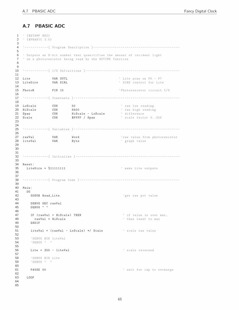
A.7 PBASIC ADC Fancy Digital Clock
A.7 PBASIC ADC
1 ’ –$STAMP BS2˝
2 ’ –$PBASIC 2.5˝
3
4 ’------------[ Program Description ]--------------------------------------------
5
6 ’ Outputs an 8-bit number that quanitifies the amount of incident light
7 ’ on a photoresistor being read by the RCTIME function
8
9
10 ’------------[ I/O Definitions ]------------------------------------------------
11
12 Lite VAR OUTL ’ Lite pins on P0 - P7
13 LiteDirs VAR DIRL ’ DIRS control for Lite
14
15 PhotoR PIN 15 ’Photoresistor circuit I/O
16
17 ’------------[ Constants ]------------------------------------------------------
18
19 LoScale CON 50 ’ raw low reading
20 HiScale CON 8400 ’ raw high reading
21 Span CON HiScale - LoScale ’ difference
22 Scale CON $FFFF / Span ’ scale factor 0..255
23
24
25 ’------------[ Variables ]------------------------------------------------------
26
27 rawVal VAR Word ’raw value from photoresistor
28 liteVal VAR Byte ’ graph value
29
30
31
32 ’------------[ Initialize ]-----------------------------------------------------
33
34 Reset:
35 LiteDirs = %11111111 ’ make Lite outputs
36
37
38 ’------------[ Program Code ]---------------------------------------------------
39
40 Main:
41 DO
42 GOSUB Read˙Lite ’get raw pot value
43
44 DEBUG DEC rawVal
45 DEBUG ” ”
46
47 IF (rawVal ¿ HiScale) THEN ’ if value is over max ,
48 rawVal = HiScale ’ then reset to max
49 ENDIF
50
51 liteVal = (rawVal - LoScale) */ Scale ’ scale raw value
52
53 ’DEBUG BIN liteVal
54 ’DEBUG ” ”
55
56 Lite = 255 - liteVal ’ scale reversed
57
58 ’DEBUG BIN Lite
59 ’DEBUG ” ”
60
61 PAUSE 50 ’ wait for cap to recharge
62
63 LOOP
64
65
43

A.7 PBASIC ADC Fancy Digital Clock
66
67 ’-----------[ Subroutines ]-----------------------------------------------------
68
69 Read˙Lite:
70 HIGH PhotoR ’charge cap
71 PAUSE 1 ’ for 1 ms
72 RCTIME PhotoR , 1, rawVal ’read the Pot
73 RETURN
44


