Centre Spatial de Liège
A LATERAL SENSOR FOR THE ALIGNMENT OF TWO
FORMATION-FLYING SATELLITES
slide 1
S. Roose(1), Y. Stockman (1), Z. Sodnik(2)
(1) Centre Spatial de Liège, Belgium(2) European Space Agency - ESA/ESTEC
5th International Conference on Spacecraft Formation Flying Missions and TechnologiesMunich City, Germany, May 29 – 31, 2013

Centre Spatial de LiègeOutline
Concept and Design
Introduction
slide 2
The instrument
Conclusions
Performance and qualification tests
5th International Conference on Spacecraft Formation Flying Missions and TechnologiesMunich City, Germany, May 29 – 31, 2013
Centre Spatial de Liège
Introduction
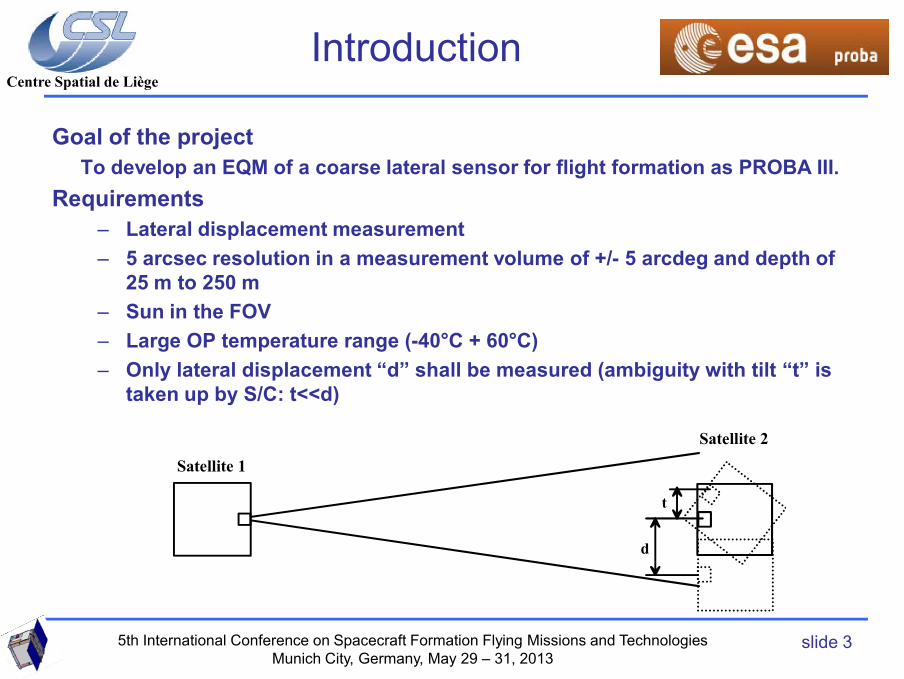
Goal of the projectTo develop an EQM of a coarse lateral sensor for flight formation as PROBA III.
Requirements– Lateral displacement measurement– 5 arcsec resolution in a measurement volume of +/- 5 arcdeg and depth of
25 m to 250 m– Sun in the FOV
Large OP temperature range ( 40°C + 60°C)
slide 3
– Large OP temperature range (-40 C + 60 C)– Only lateral displacement “d” shall be measured (ambiguity with tilt “t” is
taken up by S/C: t<<d)
d
t
Satellite 1
Satellite 2
5th International Conference on Spacecraft Formation Flying Missions and TechnologiesMunich City, Germany, May 29 – 31, 2013

Centre Spatial de Liège
CSL solution The concept •
Barrel
Cube
Filter
BS
LD
Detector unitSTAR1000Detector
Lens
EGSE Corner cube
TTL
RS422 Link
Concept and design
slide 4slide 4
LDLaser diode driver
Optical fiber
The H/W is based on detection head with single camera derived from earlier
heritage of scientific camera developments (Integral-OMC (optics, lenses),
Proba II-SWAP (camera, electronics)).
5th International Conference on Spacecraft Formation Flying Missions and TechnologiesMunich City, Germany, May 29 – 31, 2013

Centre Spatial de Liège
CLS general design
Cube
Fiber collimator
Barel
Corner cube
Source unit
Camera head
Concept and design
slide 5slide 5
• A corner cube (50 mm - diameter) on the Occulter S/C.
• A CLS telescope unit containing a barrel, lens(es), filter, cube.
• A CLS camera head unit Cypress HAS 2 CMOS APS detector.
• The centroid data is downloaded via an RS422 link to an EGSE.
• The laser diode driver is controlled via the detector unit.
• The laser diode itself is a fiber laser diode.
• A source unit powering the laser diode and detector voltages
• EGSE to manage the system
EGSE
Power Cable RS422 link
Optical fibre
5th International Conference on Spacecraft Formation Flying Missions and TechnologiesMunich City, Germany, May 29 – 31, 2013

Centre Spatial de Liège
What is critical in the system design
High SNR for high centroidisation accuracy
Dynamic range of 80 in the measurement volumeSmall integration time (camera, electronics noise reduction: 1ms)Telecentric optics (nearly absolute angle sensor)CLS signal needs to be high wrt. Sun signal level
Concept and design
slide 6
Choice of sourceNeed of 17 W optical power to have a sun/signal ratio of 1Spectral choice where detector has high sensitivity and wherepowerful lasers are available.+ rejection filter of the sun lightBUT only 8 W available from the S/C
Fiber coupled DIODE of 18W in CW, 980 nm; NA 0.22
5th International Conference on Spacecraft Formation Flying Missions and TechnologiesMunich City, Germany, May 29 – 31, 2013
Centre Spatial de Liège
CLS DU Algorithm Design
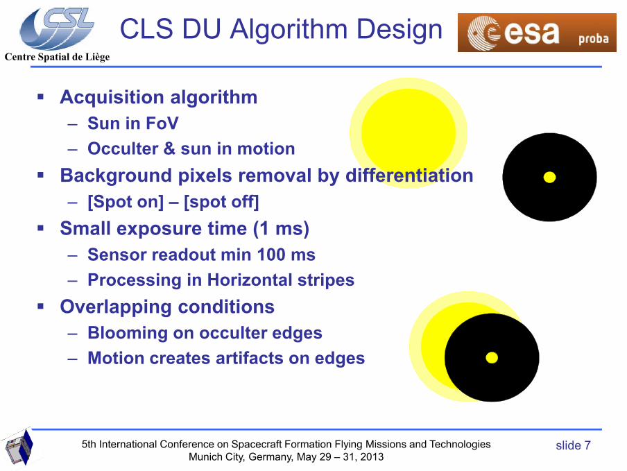
Acquisition algorithm– Sun in FoV– Occulter & sun in motion
Background pixels removal by differentiation– [Spot on] – [spot off]
Small exposure time (1 ms)
slide 7
p ( )– Sensor readout min 100 ms– Processing in Horizontal stripes
Overlapping conditions– Blooming on occulter edges– Motion creates artifacts on edges
5th International Conference on Spacecraft Formation Flying Missions and TechnologiesMunich City, Germany, May 29 – 31, 2013
Centre Spatial de Liège
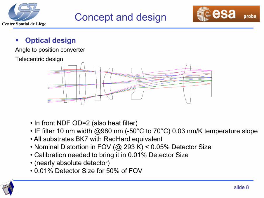
Optical designAngle to position converterTelecentric design
Concept and design
slide 8
• In front NDF OD=2 (also heat filter)• IF filter 10 nm width @980 nm (-50°C to 70°C) 0.03 nm/K temperature slope • All substrates BK7 with RadHard equivalent• Nominal Distortion in FOV (@ 293 K) < 0.05% Detector Size• Calibration needed to bring it in 0.01% Detector Size• (nearly absolute detector)• 0.01% Detector Size for 50% of FOV

Centre Spatial de Liège
D.U. Operating principles – DU controls Laser diode on/off– Reflected spot image captured on HAS2 sensor
• 1024x1024 pixels (18 µm pitch)– Operating states :
• Acquisition :
CLS Detector Unit
slide 9
– DU searches full array for valid spot– Sun in FoV => sensor blooming issue– Motion : 1 mm/s at detector level– Exposure time : 1 msec
• Tracking : – DU acquires small window “centered” on spot– DU computes CoG (=> 0,1 pixel accuracy)– CoG Readout through TM/TC
5th International Conference on Spacecraft Formation Flying Missions and TechnologiesMunich City, Germany, May 29 – 31, 2013

Centre Spatial de LiègeLaser Diode Driver
5th International Conference on Spacecraft Formation Flying Missions and TechnologiesMunich City, Germany, May 29 – 31, 2013
Centre Spatial de Liège
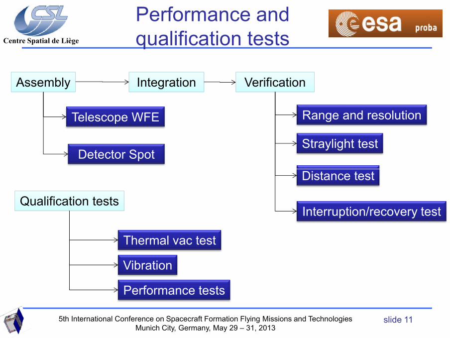
Performance and qualification tests
Assembly
Telescope WFE
Detector Spot
Integration
Range and resolution
Straylight test
Verification
slide 11
Distance test
Interruption/recovery testQualification tests
Thermal vac test
Vibration
Performance tests
5th International Conference on Spacecraft Formation Flying Missions and TechnologiesMunich City, Germany, May 29 – 31, 2013

Centre Spatial de LiègeSystem performance test
slide 12
CLS X-Calibration y = 102.36x + 493.08R2 = 1.00
0
256
512
768
1024
-5 -4 -3 -2 -1 0 1 2 3 4 5
Angle (Arcdegree)
Cen
troi
d po
sitio
n (P
ixel
)
5th International Conference on Spacecraft Formation Flying Missions and TechnologiesMunich City, Germany, May 29 – 31, 2013

Centre Spatial de LiègeStray light test
slide 13
0
200
400
600
800
1000
0 40 80 120 160 200 240 280
Time (s)
Cen
troi
d po
sitio
n(D
etec
tor p
ixel
)
5th International Conference on Spacecraft Formation Flying Missions and TechnologiesMunich City, Germany, May 29 – 31, 2013

Centre Spatial de LiègeThermal test
Operating mode Non-operating mode Switch-on Equipment
slide 14
T min T max T min T max
CLS optics: -40°C +55°C -60°C +70°C -40°C
CLS electronics: -20°C +50°C -30°C +60°C -20°C
In full temperature range for an object
located at 13.2 m.
• Accuracy 0.1 pixels centroidisation
• Focal length stability of 0.4%
• Repeatability of the optical axis of 0.3 pixels580
581
582
583
12:00:00 12:36:00 13:12:00 13:48:00 14:24:00
5th International Conference on Spacecraft Formation Flying Missions and TechnologiesMunich City, Germany, May 29 – 31, 2013

Centre Spatial de LiègeVibration test
Test Objectives Verify the survival to a vibration test. Test parameters Range and resolution test (at CSL)
CSL Functional test in situ with test corner cube Random vibration test 3-axis
• Low level sine test • Random test (25 grms) • Low level sine test
CSL Functional test in situ with test corner cube Sine vibration test 3-axis
• Low level sine test • Random test (25 grms) • Low level sine test
CSL Functional test in situ with test corner cube Range and resolution test (at CSL)
slide 15
Range and resolution test (at CSL) Success criteria Range and resolution curve shall be the same before and after
vibration test.
0
50
100
150
200
250
300
0 500 1000 1500 2000
Acce
lera
tion
(m/s
2)
Frequency (Hz)
Low level Y-sine after Y-shock test
CAM_Y
TEL_Y
REAR_Y
The camera and telescope have survived the high level
sinus, random and shock test in the 3–axis.
Stable Eigen frequencies at 239 Hz (which are above
140 Hz) as predicted in the FE model
5th International Conference on Spacecraft Formation Flying Missions and TechnologiesMunich City, Germany, May 29 – 31, 2013
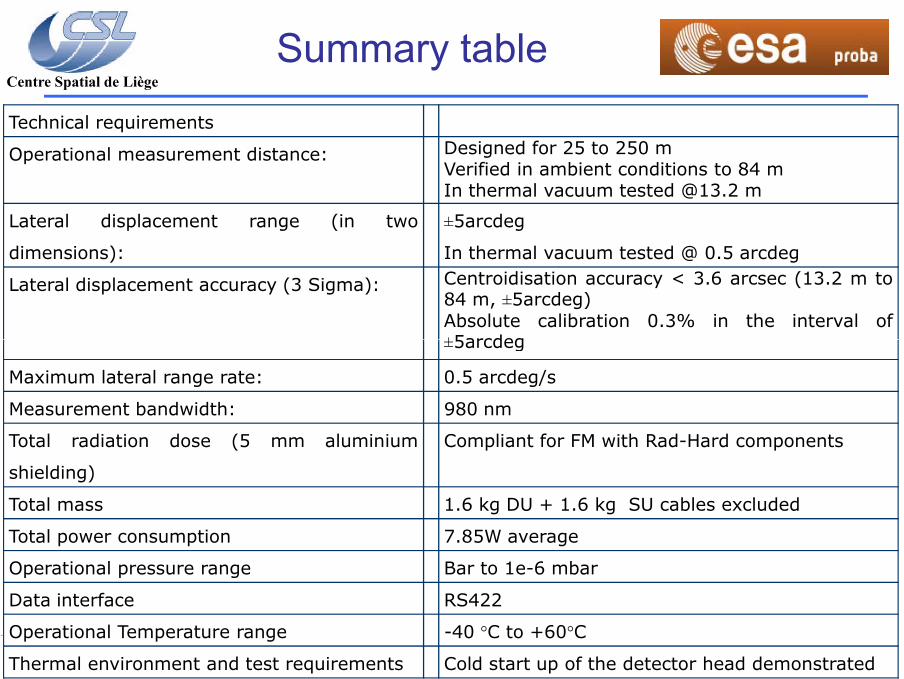
Centre Spatial de LiègeSummary table
Technical requirements
Operational measurement distance: Designed for 25 to 250 mVerified in ambient conditions to 84 mIn thermal vacuum tested @13.2 m
Lateral displacement range (in two
dimensions):
±5arcdeg
In thermal vacuum tested @ 0.5 arcdeg
Lateral displacement accuracy (3 Sigma): Centroidisation accuracy < 3.6 arcsec (13.2 m to84 m, ±5arcdeg)Absolute calibration 0.3% in the interval of±5arcdeg
slide 16
±5arcdeg
Maximum lateral range rate: 0.5 arcdeg/s
Measurement bandwidth: 980 nm
Total radiation dose (5 mm aluminium
shielding)
Compliant for FM with Rad-Hard components
Total mass 1.6 kg DU + 1.6 kg SU cables excluded
Total power consumption 7.85W average
Operational pressure range Bar to 1e-6 mbar
Data interface RS422
Operational Temperature range -40 °C to +60°C
Thermal environment and test requirements Cold start up of the detector head demonstrated
Centre Spatial de LiègeConclusion
The functional, performance and stray light tests on the CLS
have demonstrated that the CLS head is conform (@1 bar,
@293 K) in terms of:
• Position resolution of 3.6 arcsec within the FOV (with
slide 17
the sun in the FOV)
• Acquisition and tracking speed of 0.5 arcdeg/s (with
the sun in the FOV)
A CLS is ready to be used for PROBA III
5th International Conference on Spacecraft Formation Flying Missions and TechnologiesMunich City, Germany, May 29 – 31, 2013

Centre Spatial de LiègeConclusion
Thank you for your attention
Any question
slide 18
y q
5th International Conference on Spacecraft Formation Flying Missions and TechnologiesMunich City, Germany, May 29 – 31, 2013


