A PC-BASED WIRELESS AND REMOTE CONTROL FOR
SHAPE JUDGMENT EQUIPMENT USING A ZIGBEE MODULE
Ho-Chih Cheng, Min-Chie Chiu
Department of Mechanical and Automation Engineering, Chung Chou University of Science and
Technology, 6, Lane 2, Sec.3, Shanchiao Rd., Yuanlin, Changhua 51003, Taiwan, R.O.C.
Emails: [email protected], [email protected]
Submitted: Mar. 25, 2014 Accepted: July 2, 2014 Published: Sep. 1, 2014
Abstract- To increase manufacturing productivity, industrial automation is required. Additionally, in
order to monitor the manufacturing process, a remote online monitoring and control system becomes
compulsory. A conventional remote monitoring system often uses a wire connection for
communication within a control center; however, it is time-consuming and inconvenient. To overcome
this drawback, a wireless design is proposed for the manufacturing process. In this paper, a case study
of a remote wireless monitoring network used in a shape judgment system is introduced. In order to
connect the server pc and the PLC (a controller of a shape judgment system), a ZigBee wireless module
in conjunction with a transparent mode is used. Additionally, the interface of the above system is
established with a Visual Basic 6.0. One of the advantages in using a wireless network to connect with a
server pc and a shape judgment system is that the server pc is movable. Moreover, the remote
monitoring function at the client pc can also be utilized using a TCP/IP protocol. Consequently, a
prototype of a wireless network and a remote control for a shape judgment system using a ZigBee
module that reduces the cost in electrical power and saves time in the system’s installation is
exemplified.
Index terms: wireless, PC-based, ZigBee, remote.
INTERNATIONAL JOURNAL ON SMART SENSING AND INTELLIGENT SYSTEMS VOL. 7, NO. 3, SEPTEMBER 2014
1378
I. INTRODUCTION
In order to increase production in the manufacturing process, Frazelle [1] proposed an automation
system in automatic warehousing. Moreover, in order to monitor and improve the current
manufacturing progress, a monitoring and control network for the manufacturing system that uses
a network is suggested by Suesut et al. [2]. Conventional plants often use wired connections to
communicate with and control equipment. Chiu [3, 4] developed a PC-based multi-function
aquarium remote controlling system and a greenhouse automatic thermal control using a wired
connection and TCP/IP protocol in 2010. In addition, Chiu et al. [5] Presented a PC-based remote
network controlling system with three-axis robot manipulation using a TCP/IP protocol and a
wired connection between the controller (PC) and the equipment. In 2012, Cheng et al. [6]
assessed a web-based remote monitoring system for noise and temperature within an enclosed air
compressor using a wired connection. However, the wired system is expensive and time-
consuming. In addition, there is no flexibility for altering equipment allocation in the plant. In
order to avoid interference from internet wiring with the existing equipment, a wireless network
for the manufacturing system is necessary.
Ikram and Thornhill [7] assessed various wireless communication techniques used in the
automation field. They found that the WiMedia had a fast communication speed. Also, both
wireless ZigBee and wireless Bluetooth were suitable for short distance communication. Even
though there are drawbacks (slow speed and short distance communication) for the ZigBee,
because of a simpler system structure and lower electric power exhaust, the ZigBee module is
widely used in wireless sensing and is increasingly used in automation monitoring systems.
Palanisamy et al. [8] developed a wireless monitoring system for controlling the DC motor,
temperature, and lighting using a wireless ZigBee. Palit [9] designed wireless communication
sensing networks for tunnels, trains and building. Ding et al. [10] established an environmental
monitoring system using a wireless ZigBee module. Wang et al. [11] presented an intelligent
fuzzy controller for air-conditioning with Zigbee sensors. Ropponen et al. [12] also developed a
low-frequency localization and identification system with a ZigBee network. Moreover, Wang et
al. [13] developed a visual navigation and remote monitoring system for an agricultural robot
using a wireless local area network (LAN), a slave computer, and a host computer.
Ho-Chih Cheng and Min-Chie Chiu, A PC-BASED WIRELESS AND REMOTE CONTROL FOR SHAPE JUDGMENT EQUIPMENT USING A ZIGBEE MODULE
1379
In this paper, to reduce manpower in a shape-judged system, a remote wireless monitoring and
control system for a shape-judged system is assessed and exemplified. To overcome the above
drawbacks, a set of wireless ZigBee modulus used to communicate between the server pc and the
programmable logic unit (PLC) is adopted. Moreover, a remote control and monitoring system at
the client pc using a TCP/IP protocol is also used.
II. A PC-BASED REMOTE WIRELESS MONITORING AND CONTROL SYSTEM
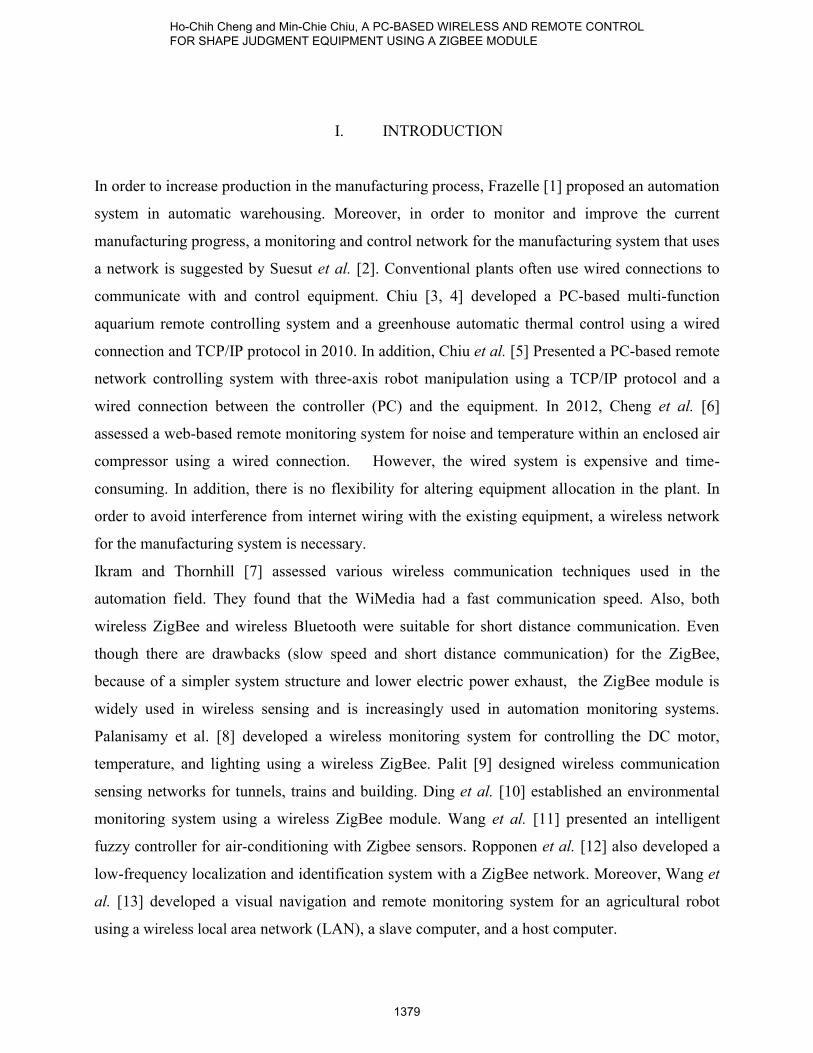
The connection of the monitoring system is shown in Fig.1. As indicated in Fig. 1, one piece of
shape-judged equipment is controlled by the programmable logic controller (PLC). The PLC will
communicate with the near field (server pc) via the ZigBee wireless network. Moreover, the
remote field (client pc) will audit the shape-judged equipment via the TCP/IP protocol [3, 4, 5].
Fig. 1 The connection of the monitoring system
a. Function of the Shape-judged Equipment
As indicated in Fig. 2 [14], the working pieces in both the circular shape and rectangular shape
will be fed into the system at location A via a conveyor. Shape recognition for the work piece
using a sensor will be performed at location A. Concerning the circular shape, the work piece will
be forwarded to location C by using a bridge type robotic arm; otherwise, the work piece with a
rectangular shape will be sent to location D.
INTERNATIONAL JOURNAL ON SMART SENSING AND INTELLIGENT SYSTEMS VOL. 7, NO. 3, SEPTEMBER 2014
1380

Fig. 2 The shape judgment equipment [14]
b. Shape Judgment Equipment Sensor
The proximity switch used to detect an object has been widely adopted in the automation field.
The SA in Fig.2 is a sensor for feeding the working piece. It is a photoelectric sensor. The object
is identified by projecting a light ray to on it, reflecting that lighting to a receiver, and judging the
received light intensity. Moreover, the SB in Fig.2, a sensor for a circular piece, can identify
both circular shapes and rectangular shapes. It is a capacitive sensor. A high frequency magnetic
field on the electrode panel will be induced when the object is close to the sensor. The motion
and position of the object can be predicted by observing the sensor’ s variance of capacitance.
c. System Operation and the PLC’ s Communication Format
An FX2n PLC (Mitsubishi brand) with a 32-bite CPU is adopted for the system. There are
sixteen input joints (X0-X7 and X10-X17) and sixteen output joints (Y0-Y7 and Y10-Y17). To
facilitate control by the PLC, the X and Y joints are connected to the related sensors and
actuators. Moreover, a RS-422 port which is used to communicate with the server pc to read in
/write out the PLC program is built into the FX2n PLC. To facilitate the near field monitor, the
RS-232 serial interface at the server pc is connected to the RS-422 port at the PLC. In addition,
the system’ s server pc and the PLC will serve as the master and the slave. The master (server
Ho-Chih Cheng and Min-Chie Chiu, A PC-BASED WIRELESS AND REMOTE CONTROL FOR SHAPE JUDGMENT EQUIPMENT USING A ZIGBEE MODULE
1381

pc) will actively submit the command to the slave (PLC). Also, the slave (PLC) will respond to
the message after it receives the command from the master. The slave cannot actively submit the
command to the master.
The communication parameters between the server pc and the PLC include the following:
· Transmission format: RS232, asynchronous, and two-way transmission.
· Transmission rate: 9600 bps.
· Parity check: even parity.
· Data bit: 7 bits.
· Stop bit: 1 bit.
· Data comparison: checksum detection.
· Transmission character: ASCII code.
As indicated in Table 1, the command format submitted from the server pc to the PLC is
composed of a head code, a command, an address/data, a stop code, and a checking code. The
related features are listed below:
Table 1: The command format of the host computer port
The head code Command code Address/data The end code Checking code
STX
(02H)
CMD DATA ETX
(03H)
SUM
Here, head code (STX) is the first bit of the command string set as 02H. Command code, one bit,
is the length of the command code shown in Table 2.
Table 2: The category of command for the host computer port
Command code Object Function
0 XYMSTCD Read the data from the grouped
element
1 YMSTCD Write the data into the grouped
element
7 YMSTC Force single joint to be ON
8 YMSTC Force single joint to be OFF
INTERNATIONAL JOURNAL ON SMART SENSING AND INTELLIGENT SYSTEMS VOL. 7, NO. 3, SEPTEMBER 2014
1382

The address and data indicate that the object’s initial address and numbers in the PLC shall be
given before a read/write to the PLC is performed. The end code (ETX) is the last bit of the
command format set as 03H. Moreover, the checking code (SUM) is the summation of the related
ASCII with respect to the command code, address/data, and end code. The last two bits of the
total ASCII data are extracted and serve as the checking code (SUM code).
The PLC will analyze the command (submitted from the server pc), execute the mission, and
respond to the server pc. Here, a response will be made when the PLC receives a command code
of 0. The response format is shown in Table 3. In addition, the response format for a command
code of 1, 7, and 8 from the PLC is ACK (06H) if the PLC can recognize the command. The PLC
will respond to the server pc using NAK (15H) if it cannot recognize the command.
Table 3: The response format of the command code 0 for the host computer
Head code 1st data set 2
nd data
set
… Last data
set
End code Checking
code
STX
(02H)
ETX
(03H)
SUM
d. ZigBee Wireless Network
The ZigBee is a short-distance communication technique. It is organized using a Physical layer
(PHY), a Media Access Control Layer (MAC), and a Data Link. All are specified by the IEEE
802.15.4. Moreover, the logic network, the data transmission, the applied interface specification,
and the communication specification for the products are specified by the ZigBee Alliance.
The effective distance for the ZigBee transmission is between 150~200 meters. The data
transmission rate is 20K~250K bps. Because it has a lower effective transmission distance and
rate than the Wi-Fi and the Blue-tooth, the ZigBee is confined to a lower data transmission field.
However, because of low electrical exhaust, large network nodes, and low cost, the ZigBee has
been developed for environmental monitoring, automatic control, process monitoring, building
automation, and medical sensing.
The ZigBee wireless module used in this paper is the IP-Link series (Helicomm brand). It
provides the system with a RS-232/RS-485 interface. In addition, the ZigBee uses a full mesh in
Ho-Chih Cheng and Min-Chie Chiu, A PC-BASED WIRELESS AND REMOTE CONTROL FOR SHAPE JUDGMENT EQUIPMENT USING A ZIGBEE MODULE
1383

the network structure. It also has Master/Slave characteristics and can perform a two-way
communication. A frequency range of 900MHz and 2.4GH (free of charge) is also used.
The IP-Link provides three kinds of modes: a binary protocol mode, a transparent-broadcast
mode, and a transparent – P2P mode.
· Binary protocol mode:
Based on the command format of the ZigBee, a binary command is written by the user. The
data packet submitted from the pc (server pc) will be transmitted to the IP-Link Master via the
RS-232/RS-485 protocol. Thereafter, according to the communication format, the IP-Link
Master will send data to the specified IP-Link Client. The IP-Link Client will routinely send
back data to the IP-Link Master. The related data will also be forwarded to the pc (server pc) via
the RS-232/RS-485 protocol.
· Transparent-broadcast mode:
Aside from the ZigBee’s command format, the user can freely submit the data to the IP-Link
Master via the RS-232/RS-485 protocol. The IP-Link Master will then send the data to all the
IP-Link Clients linked in the ZigBee network. Similarly, all the IP-Link Clients will be preset
to send back the data to the IP-Link Master. Also, the IP-Link Master will forward the data to
the pc (server pc) via the RS-232/RS-485 protocol.
· Transparent – P2P mode:
Aside from the ZigBee’s command format, the user can freely submit the data to the IP-Link
Master via the RS-232/RS-485 protocol. The IP-Link Master will then send the data to the
specified IP-Link Clients. The IP-Link Client will be preset to send back the data to the IP-
Link Master. The related data will also be forwarded to the pc (server pc) via the RS-232/RS-
485 protocol.
The transparent P2P mode is adopted in this paper. The ZigBee wireless network can also
function as the wireless RS-232/RS-422 tunnel.
e. Monitoring Host PC
The monitoring host pc includes a near port (server pc) and a remote port (client pc). An interface
programmed by the VB 6.0 is used to link both the server pc and the client pc.
INTERNATIONAL JOURNAL ON SMART SENSING AND INTELLIGENT SYSTEMS VOL. 7, NO. 3, SEPTEMBER 2014
1384
· Server port:
The server port (server pc) provides two paths of communication: one is between the server pc
and the PLC via the serial RS-232 protocol; the other is between the server pc and the client pc
via the TCP/IP. Multiple client pcs can be logged into the server pc simultaneously.
· Client port:
A monitoring interface will be provided on the client pc’s screen. The user can operate the
interface dialogue to send the command to the server pc via the TCP/IP protocol. Moreover, the
server pc will also execute the command to implement the near port equipment.
III. EXPERIMENTAL RESULTS
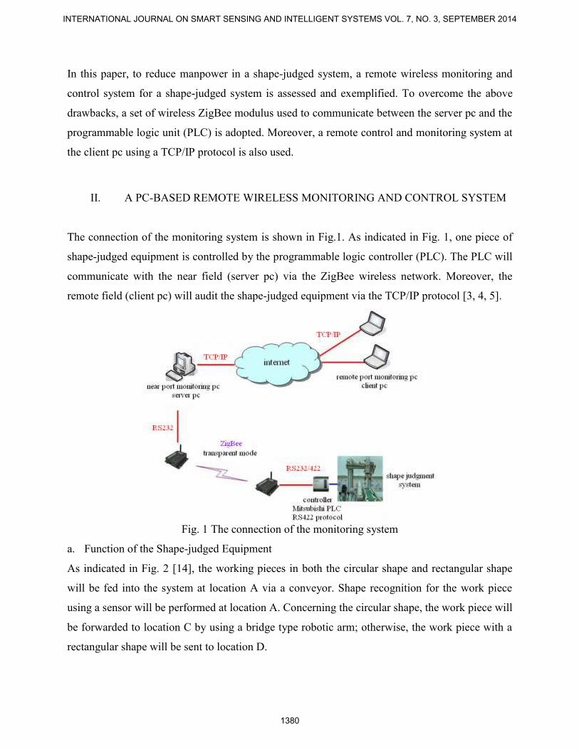
The experimental work for the wireless network and a remote control for a shape judgment
system have been performed using the interface of the server pc shown in Fig. 19. First, a
rectangular piece is placed in the feeding place. As indicated in Figs. 3 and 4, a rectangular piece
is detected, identified, and gripped by the gripper. Figs. 5-8 indicate that the rectangular piece is
transported to the targeted discharging place (p2) by the robotic arm.
Figure 3. Detection of a rectangular piece
Ho-Chih Cheng and Min-Chie Chiu, A PC-BASED WIRELESS AND REMOTE CONTROL FOR SHAPE JUDGMENT EQUIPMENT USING A ZIGBEE MODULE
1385

Figure 4. Gripping of a rectangular piece
Figure 5. Movement of a rectangular piece (step 1)
INTERNATIONAL JOURNAL ON SMART SENSING AND INTELLIGENT SYSTEMS VOL. 7, NO. 3, SEPTEMBER 2014
1386
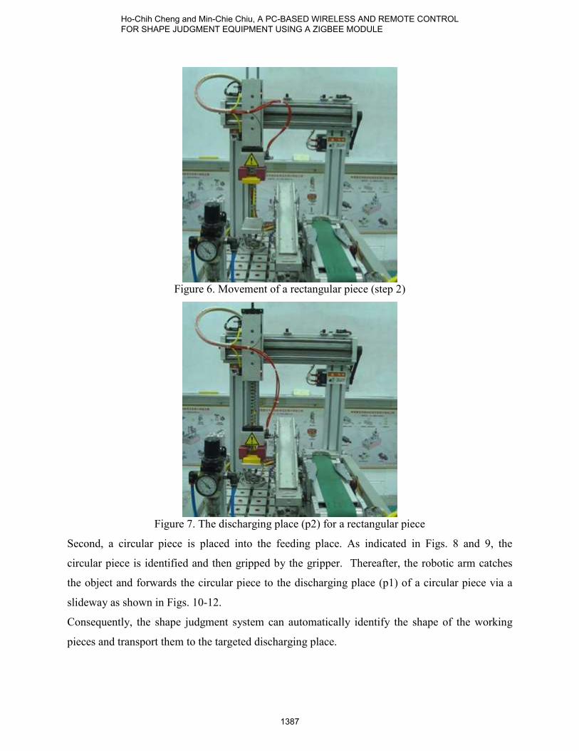
Figure 6. Movement of a rectangular piece (step 2)
Figure 7. The discharging place (p2) for a rectangular piece
Second, a circular piece is placed into the feeding place. As indicated in Figs. 8 and 9, the
circular piece is identified and then gripped by the gripper. Thereafter, the robotic arm catches
the object and forwards the circular piece to the discharging place (p1) of a circular piece via a
slideway as shown in Figs. 10-12.
Consequently, the shape judgment system can automatically identify the shape of the working
pieces and transport them to the targeted discharging place.
Ho-Chih Cheng and Min-Chie Chiu, A PC-BASED WIRELESS AND REMOTE CONTROL FOR SHAPE JUDGMENT EQUIPMENT USING A ZIGBEE MODULE
1387
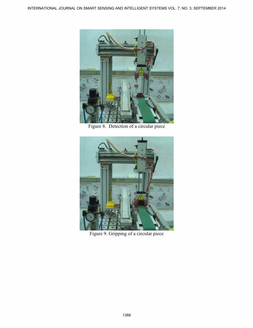
Figure 8. Detection of a circular piece
Figure 9. Gripping of a circular piece
INTERNATIONAL JOURNAL ON SMART SENSING AND INTELLIGENT SYSTEMS VOL. 7, NO. 3, SEPTEMBER 2014
1388

Figure 10. Movement of a circular piece (step 1)
Figure 11. Movement of a circular piece (step 2)
Ho-Chih Cheng and Min-Chie Chiu, A PC-BASED WIRELESS AND REMOTE CONTROL FOR SHAPE JUDGMENT EQUIPMENT USING A ZIGBEE MODULE
1389
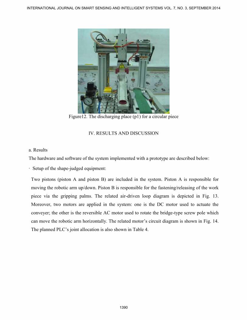
Figure12. The discharging place (p1) for a circular piece
IV. RESULTS AND DISCUSSION
a. Results
The hardware and software of the system implemented with a prototype are described below:
· Setup of the shape-judged equipment:
Two pistons (piston A and piston B) are included in the system. Piston A is responsible for
moving the robotic arm up/down. Piston B is responsible for the fastening/releasing of the work
piece via the gripping palms. The related air-driven loop diagram is depicted in Fig. 13.
Moreover, two motors are applied in the system: one is the DC motor used to actuate the
conveyer; the other is the reversible AC motor used to rotate the bridge-type screw pole which
can move the robotic arm horizontally. The related motor’s circuit diagram is shown in Fig. 14.
The planned PLC’s joint allocation is also shown in Table 4.
INTERNATIONAL JOURNAL ON SMART SENSING AND INTELLIGENT SYSTEMS VOL. 7, NO. 3, SEPTEMBER 2014
1390

Figure13. The related air-driven loop diagram
Figure14. The motor’s circuit diagram
Table 4 Planning of PLC’s joint
Input point Output point
X0 St: start up Y0 M1+: conveyer’s motor ON
X1 P0: location of the robotic arm Y1 M2+: robot arm move left
X2 P1: location of the robotic arm Y2 M2-: robot arm move right
X3 P2: location of the robotic arm Y3 A+: perpendicular piston
move forward
X4 SB: sensor for circular piece Y4 A-: perpendicular piston
move backward
X5 SA: sensor for rectangular piece Y5 B+: air-driven grip palm ON
(catching)
X6 a0: upper LS of the piston Y6 B-: air-driven grip palm
OFF (loosen)
X7 a1: lower LS of the piston Y10 GL: green light ON
Ho-Chih Cheng and Min-Chie Chiu, A PC-BASED WIRELESS AND REMOTE CONTROL FOR SHAPE JUDGMENT EQUIPMENT USING A ZIGBEE MODULE
1391

X10 EMS: emergent stop Y11 RL: red light ON
X11 COS1: reset Y12 YL: yellow light ON
X12 COS2: step by step procedure
· PLC program:
The related design diagram of the PLC’s control program is shown in Fig. 15.
Figure 15. The design diagram of the PLC’s control program
· Planning of the interface joints between the PC and the PLC:
INTERNATIONAL JOURNAL ON SMART SENSING AND INTELLIGENT SYSTEMS VOL. 7, NO. 3, SEPTEMBER 2014
1392

In order to monitor and control the PLC via the server pc serial communication, the M joints of
the auxiliary relays are added to the PLC program. The M joint is connected in parallel with the
related push button (X joint). The related planning of the interface joints is shown in Table 5.
Table 5 PLC planning of M joint (auxiliary relay) in the PLC
Button Auxiliary joint
st M100
EMS M101
COS1 M102
COS2 M103
· Setting for the ZigBee wireless module:
The parameters of the ZigBee wireless module (IP-Link) should be initialized in advance by
using tool software before the system is started. The IP-Link connected to the RS-232 at the
server pc is defined as the Master. The related parameter setting is also shown in Fig. 16. As
indicated in Fig. 16, the Master is selected at the Node Type column and the Node ID is
automatically preset at 0. In addition, in order to setup the IP-Link to the Client that is
connected to the RS-232 at the PLC, the parameter setting process is performed and shown in
Fig. 17. As indicated in Fig. 17, the Client is selected at the Node Type column and the Node ID
is preset as any number except 0. Moreover, the setting for other parameters such as the Channel
and the Net ID preset in the IP-Link Master and the IP-Link Client should be the same. Also, the
Mesh is selected from the Topology column. Consequently, as indicated in Fig. 18, the
transparent mode will be established when serial communication is setup.
Ho-Chih Cheng and Min-Chie Chiu, A PC-BASED WIRELESS AND REMOTE CONTROL FOR SHAPE JUDGMENT EQUIPMENT USING A ZIGBEE MODULE
1393

Figure 16. The parameter setting for the IP-Link Master at the server pc
Figure 17. The parameter setting for the IP-Link Client at the client pc
INTERNATIONAL JOURNAL ON SMART SENSING AND INTELLIGENT SYSTEMS VOL. 7, NO. 3, SEPTEMBER 2014
1394
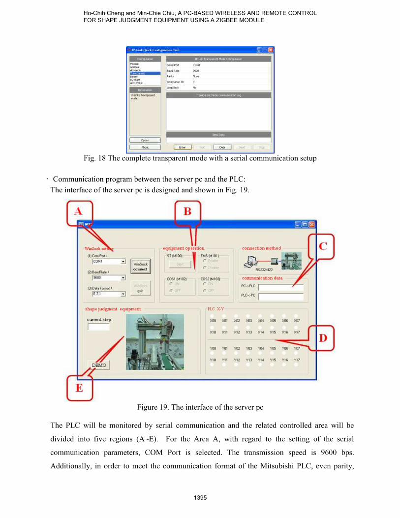
Fig. 18 The complete transparent mode with a serial communication setup
· Communication program between the server pc and the PLC:
The interface of the server pc is designed and shown in Fig. 19.
Figure 19. The interface of the server pc
The PLC will be monitored by serial communication and the related controlled area will be
divided into five regions (A~E). For the Area A, with regard to the setting of the serial
communication parameters, COM Port is selected. The transmission speed is 9600 bps.
Additionally, in order to meet the communication format of the Mitsubishi PLC, even parity,
Ho-Chih Cheng and Min-Chie Chiu, A PC-BASED WIRELESS AND REMOTE CONTROL FOR SHAPE JUDGMENT EQUIPMENT USING A ZIGBEE MODULE
1395
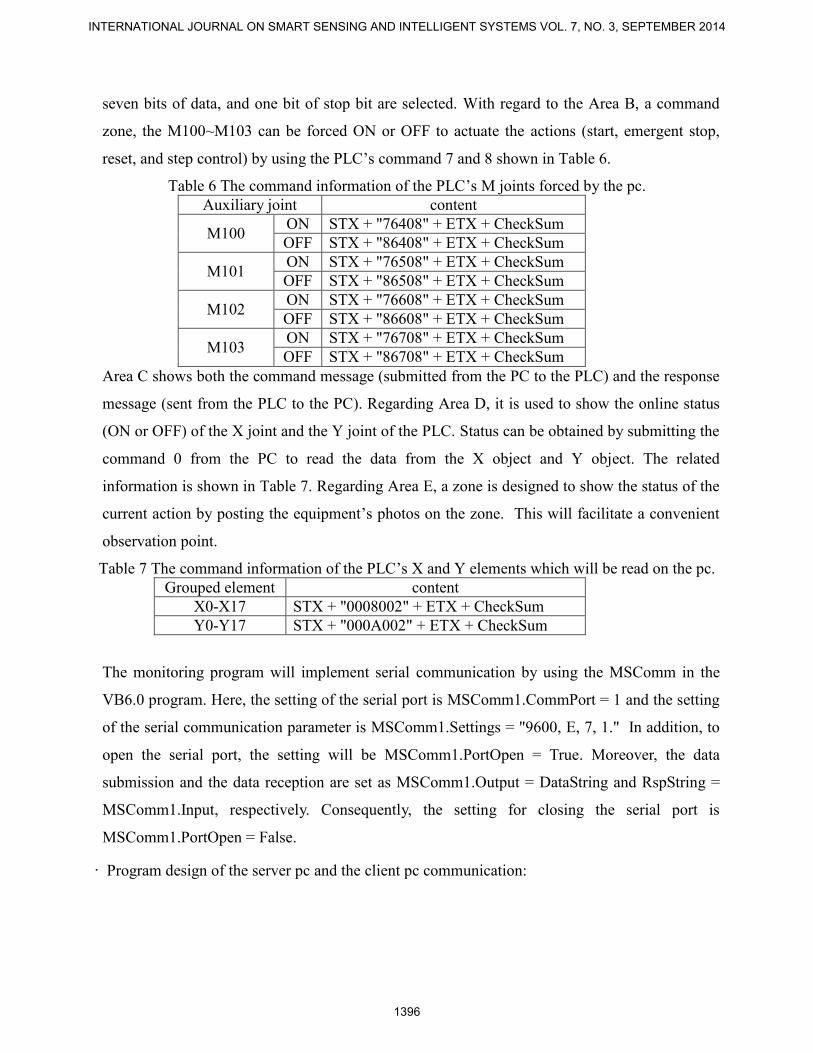
seven bits of data, and one bit of stop bit are selected. With regard to the Area B, a command
zone, the M100~M103 can be forced ON or OFF to actuate the actions (start, emergent stop,
reset, and step control) by using the PLC’s command 7 and 8 shown in Table 6.
Table 6 The command information of the PLC’s M joints forced by the pc.
Auxiliary joint content
M100 ON STX + "76408" + ETX + CheckSum
OFF STX + "86408" + ETX + CheckSum
M101 ON STX + "76508" + ETX + CheckSum
OFF STX + "86508" + ETX + CheckSum
M102 ON STX + "76608" + ETX + CheckSum
OFF STX + "86608" + ETX + CheckSum
M103 ON STX + "76708" + ETX + CheckSum
OFF STX + "86708" + ETX + CheckSum
Area C shows both the command message (submitted from the PC to the PLC) and the response
message (sent from the PLC to the PC). Regarding Area D, it is used to show the online status
(ON or OFF) of the X joint and the Y joint of the PLC. Status can be obtained by submitting the
command 0 from the PC to read the data from the X object and Y object. The related
information is shown in Table 7. Regarding Area E, a zone is designed to show the status of the
current action by posting the equipment’s photos on the zone. This will facilitate a convenient
observation point.
Table 7 The command information of the PLC’s X and Y elements which will be read on the pc.
Grouped element content
X0-X17 STX + "0008002" + ETX + CheckSum
Y0-Y17 STX + "000A002" + ETX + CheckSum
The monitoring program will implement serial communication by using the MSComm in the
VB6.0 program. Here, the setting of the serial port is MSComm1.CommPort = 1 and the setting
of the serial communication parameter is MSComm1.Settings = "9600, E, 7, 1." In addition, to
open the serial port, the setting will be MSComm1.PortOpen = True. Moreover, the data
submission and the data reception are set as MSComm1.Output = DataString and RspString =
MSComm1.Input, respectively. Consequently, the setting for closing the serial port is
MSComm1.PortOpen = False.
· Program design of the server pc and the client pc communication:
INTERNATIONAL JOURNAL ON SMART SENSING AND INTELLIGENT SYSTEMS VOL. 7, NO. 3, SEPTEMBER 2014
1396
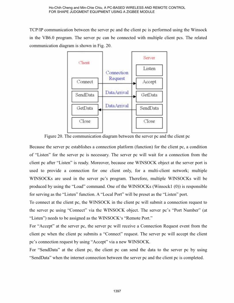
TCP/IP communication between the server pc and the client pc is performed using the Winsock
in the VB6.0 program. The server pc can be connected with multiple client pcs. The related
communication diagram is shown in Fig. 20.
Figure 20. The communication diagram between the server pc and the client pc
Because the server pc establishes a connection platform (function) for the client pc, a condition
of “Listen” for the server pc is necessary. The server pc will wait for a connection from the
client pc after “Listen” is ready. Moreover, because one WINSOCK object at the server port is
used to provide a connection for one client only, for a multi-client network; multiple
WINSOCKs are used in the server pc’s program. Therefore, multiple WINSOCKs will be
produced by using the “Load” command. One of the WINSOCKs (Winsock1 (0)) is responsible
for serving as the “Listen” function. A “Local Port” will be preset as the “Listen” port.
To connect at the client pc, the WINSOCK in the client pc will submit a connection request to
the server pc using “Connect” via the WINSOCK object. The server pc’s “Port Number” (at
“Listen”) needs to be assigned as the WINSOCK‘s “Remote Port.”
For “Accept” at the server pc, the server pc will receive a Connection Request event from the
client pc when the client pc submits a “Connect” request. The server pc will accept the client
pc’s connection request by using “Accept” via a new WINSOCK.
For “SendData” at the client pc, the client pc can send the data to the server pc by using
“SendData” when the internet connection between the server pc and the client pc is completed.
Ho-Chih Cheng and Min-Chie Chiu, A PC-BASED WIRELESS AND REMOTE CONTROL FOR SHAPE JUDGMENT EQUIPMENT USING A ZIGBEE MODULE
1397
For “GetData” at the server pc, the server pc will receive a Data Arrival event from the client pc
when the client pc sends data to the server pc. At the same time, the server pc will also receive
data by way of “GetData.”
For “GetData” at the client pc, the client pc will produce a DataArrival event when the server pc
sends data to the client pc. Simultaneously, the client pc will also receive data by using
“GetData.”
For “Close”, the connection is ended using “Close” when the purpose of the communication is
achieved.
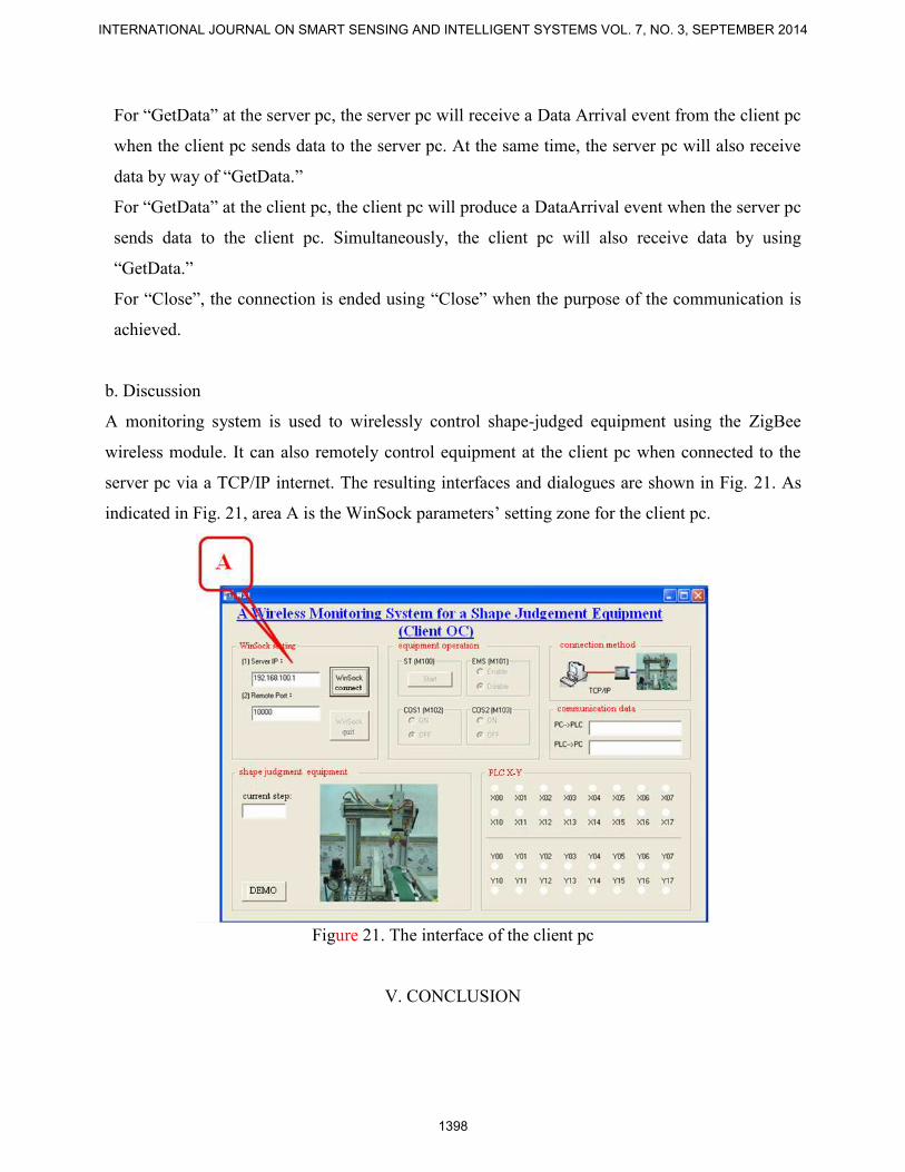
b. Discussion
A monitoring system is used to wirelessly control shape-judged equipment using the ZigBee
wireless module. It can also remotely control equipment at the client pc when connected to the
server pc via a TCP/IP internet. The resulting interfaces and dialogues are shown in Fig. 21. As
indicated in Fig. 21, area A is the WinSock parameters’ setting zone for the client pc.
Figure 21. The interface of the client pc
V. CONCLUSION
INTERNATIONAL JOURNAL ON SMART SENSING AND INTELLIGENT SYSTEMS VOL. 7, NO. 3, SEPTEMBER 2014
1398

It has been shown that a near port/remote port monitoring and control online system for shape-
judged equipment is established using the internet in conjunction with a ZigBee wireless module
and serial communication techniques. The monitoring system’s structure is based on the PC. The
interfaces of the server pc and the client pc are programmed using the VB6.0 program. In
addition, the server pc will communicate with the PLC using the ZigBee wireless module.
Therefore, shape-judged equipment can be wirelessly monitored and controlled online.
Moreover, the shape-judged equipment can also be remotely monitored and controlled at the
client pc using a connection between the server pc and the client pc via a TCP/IP internet.
The user can obtain the current status of the X joint and the Y joint on the monitoring screen (at
server pc/client pc). The related actions such as start, emergent stop, reset, and step motion will
be implemented by the user via the M joint. The corresponding photo of the action posted on the
screens (at server pc/ client pc) will also be updated simultaneously.
Consequently, an online monitoring system that can remotely and wirelessly control shape-
judged equipment indeed provides an economical way to reduce manpower.
ACKNOWLEDGMENTS
The authors acknowledge the financial support of the Project (PC101160402).
REFERENCES
[1] E. Frazelle, “Design problems in automated warehousing”, Proceedings of IEEE International
Conference on Robotics and Automation, Vol., 3, 1986, pp. 486-489.
[2] T. Suesut, V. Tipsuwanporn, S. Gulphanich, J. Rodcumtui, P.T. Sukprasert, “A design of
automatic warehouse for internet based system”, Proceedings of IEEE International Conference
on Industrial Technology, 2002, pp. 313-316.
[3] M.C. Chiu, “A multi-function aquarium equipped with automatic thermal control/fodder-
feeding/water treatment using network remote controlling system”, Information Technology
Journal, Vol. 9, No.7, 2010, pp. 1458-1466.
[4] M.C. Chiu, “An automatic thermal control on greenhouse using network remote controlling
system”, Journal of Applied Sciences, Vol. 10, No. 17, 2010, pp. 1944-1950.
[5] M.C. Chiu, T.S. Lan, H.C. Cheng, “A three-axis robot manipulation using remote network
Ho-Chih Cheng and Min-Chie Chiu, A PC-BASED WIRELESS AND REMOTE CONTROL FOR SHAPE JUDGMENT EQUIPMENT USING A ZIGBEE MODULE
1399

controlling system”, Engineering, Vol. 2, 2010, pp. 874-878.
[6] H. C. Cheng, M.C. Chiu, C.L. Huang, P.C. Chuo, “A development of a web-based Remote
monitoring system in the noise and thermal of an enclosed air compressor”, Information
Technology Journal, Vol. 11, No. 6, 2012, pp. 686-698.
[7] W. Ikram and N. F. Thornhill, “Wireless communication in process automation: a survey of
opportunities, requirements, concerns and challenges”, Proceedings UKACC International
Conference Control 2010, Coventry, UK, 7-10 Sept. 2010, pp. 1-6.
[8] S. Palanisamy, S. S. Kumar, and J. L. Narayanan, “Secured wireless communication for
industrial automation and control”, Procceedings 2011 3rd International Conference Electronics
Computer Technology, Kanyakumari, India, 8-10 Apr. 2011, pp. 168-171.
[9] S.K. Palit, “Design of wireless communication sensing networks for tunnels, trains and
building”, International Journal on Smart Sensing and Intelligent Systems, Vol. 2, No. 1, 2009,
pp.118-134.
[10] F. Ding, G. Song, K. Yin, J. Li, A. Song, “Design and implementation of ZigBee based
gateway for environmental monitoring system”, International Conference on Communication
Technology Proceedings, ICCT, 2008, pp. 93-96.
[11] T.M. Wang, I.J. Liao, J.C. Liao, T.W. Suen, W.T. Lee, “An intelligent fuzzy controller for
air-condition with Zigbee sensors”, International Journal on Smart Sensing and Intelligent
Systems, Vol. 2, No. 4, 2009, pp. 636-652.
[12] A. Ropponen, M. Linnavuo, R. Sepponen, “Low-Frequency localization and identification
system with Zigbee network”, International Journal on Smart Sensing and Intelligent Systems,
Vol. 4, No. 1, 2011, pp. 75-93.
[13] Y. Wang, F. Yang1, T. Wang, Q. Liu, X. Xu, “Research on visual navigation and remote
monitoring technology of agricultural robot”, International Journal on Smart Sensing and
Intelligent Systems, Vol. 6, No. 2, 2013, pp. 466-481.
[14] Council of Labor Affairs, “Technician Certificate for Mechatronics – Practical Testing”,
Department of Executive, Taiwan, 2008.
INTERNATIONAL JOURNAL ON SMART SENSING AND INTELLIGENT SYSTEMS VOL. 7, NO. 3, SEPTEMBER 2014
1400


