
A STUDY OF LIQUID METAL FILM FLOW, UNDER FUSION RELEVANT MAGNETIC FIELDS
M. Narula, A. Ying and M.A. Abdou
Fusion Engineering Sciences, MAE Department, UCLA, Los Angeles CA 90095-1597. [email protected]
The use of flowing liquid metal streams or “liquidwalls” as a plasma contact surface is a very attractive
option and has received considerable attention over thepast several years both in the plasma physics and fusion
engineering programs. A key issue for the feasibility of
flowing liquid metal plasma facing component (PFC)systems, lies in their magnetohydrodynamic (MHD)
behavior. The spatially varying magnetic field
environment, typical of a fusion device can lead to seriousflow disrupting MHD forces that hinder the development
of a smooth and controllable flow needed for PFC
applications. The present study builds up on the ongoingresearch effort at UCLA, directed towards providing
qualitative and quantitative data on liquid metal free
surface flow behavior under fusion relevant magneticfields, to aid in better understanding of flowing liquid
metal PFC systems.
I. INTRODUCTION
Liquid metal free surface flows or “liquid walls”
have the potential to be become ideal plasma contact
surfaces inside a fusion device. This comes from the
ability of some liquid metals, like lithium to pump
hydrogen and getter impurities and hence act as an active
particle control agent. In addition, liquid metal streams
can handle the colossal heat fluxes, pounding on the
plasma facing components and alleviate the very serious
problem of melting and erosion, inevitably present in all
the solid plasma facing components (PFC). However,
flowing free surface liquid metal PFC systems have their
own unique set of issues, the most prominent of these
being the presence of strong flow disrupting
magnetohydrodynamic (MHD) forces created due to
liquid motion in a complex spatially and temporally
varying magnetic field environment. Rapid deceleration
of the flow accompanied by the thickening of the fluid
film, unwanted flow deflection, creation of bare spots
with no fluid protection, creation of regions of thick
stagnant fluid leading to hot spots, stream wise and span
wise variation of fluid film thickness are some of the
MHD effects that need utmost attention and must be
addressed to ensure a smooth, controllable and predictable
flow of liquid metal streams for PFC applications.
The research effort at UCLA has been actively
pursuing the behavior of free surface liquid metal flows
under fusion relevant magnetic fields, to help answer
some of the above mentioned issues. The Magnetic Torus
(MTOR) facility at UCLA can closely simulate the three
component ‘1/R’ field, typical of toroidal fusion devices.
Apart from this, assortments of strong permanent magnets
are used to reproduce the required magnetic fields. The
liquid metal used for the study is a eutectic of gallium
indium and tin (Ga-67%, In-20.5%, Sn-12.5%) and is
preferred over lithium because of safety issues and ease of
handling and operation. The liquid metal is harbored
inside a flow loop powered by an electromagnetic pump.
Various test sections can be attached to the loop to
conduct different studies. In the first set of experiments
performed, a stainless steel channel with a wall thickness
of 0.5mm was used. The channel was 34cm long and 5cm
wide. The applied magnetic field was a scaled
reproduction of the NSTX1 divertor magnetic field
conditions. The scaling was required to match the non
dimensional Hartmann number, as gallium alloy was
being used instead of liquid lithium, it being the actual
design liquid. Inductive probes were used to measure the
thickness of the fluid film over the substrate. Interesting
insights were obtained from these experiments. It was
observed that the film thickness varies considerably over
the length of the channel. As much as six times increase
in the film thickness was observed at the downstream
measurement location. It was also ascertained by
experiments that the wall normal component of the
magnetic field had the most profound effect on the local
film thickness. For additional details see [1]. The next
step to these preliminary findings was to test more
realistic divertor geometry in a better reproduction of the
scaled NSTX wall normal field component and that is the
subject of this paper.
The next section describes the new experimental test
channel and the new optical diagnostic system developed
to obtain the film thickness. Section III highlights the
important observations and results from the experiments.
To supplement the experiments and to get a better insight
into the phenomenon, a conscious numerical modeling
effort has been started. ‘HIMAG’, a unique code
developed by HyPerComp Inc. is being modified to apply
it to the problem at hand. HIMAG is a three dimensional,
incompressible MHD free surface code. Section IV 1 NSTX: National Spherical Torus Experiment
564 FUSION SCIENCE AND TECHNOLOGY VOL. 47 APR. 2005
describes the important features of the code and the
preliminary results obtained from numerical simulation.
Section V describes the important results and conclusions
so far and also the future work planned both with regards
to the experiments and numerical modeling.
II. EXPERIMENT SET UP
II.A Test Section
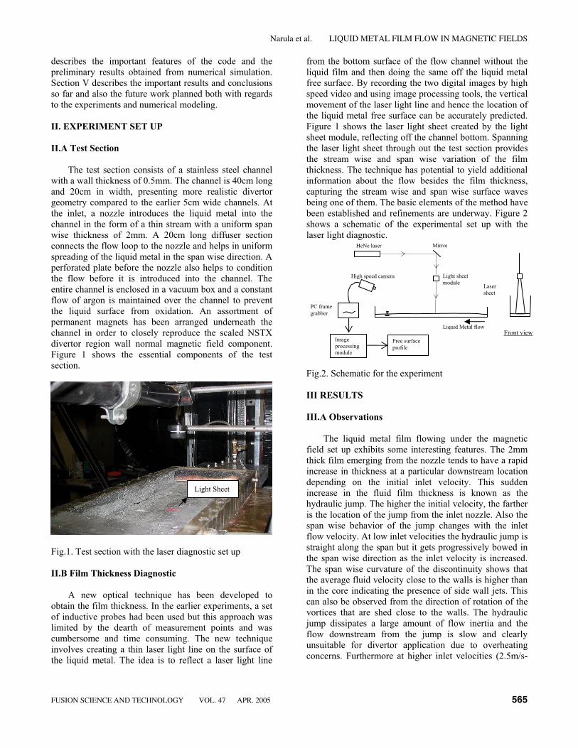
The test section consists of a stainless steel channel
with a wall thickness of 0.5mm. The channel is 40cm long
and 20cm in width, presenting more realistic divertor
geometry compared to the earlier 5cm wide channels. At
the inlet, a nozzle introduces the liquid metal into the
channel in the form of a thin stream with a uniform span
wise thickness of 2mm. A 20cm long diffuser section
connects the flow loop to the nozzle and helps in uniform
spreading of the liquid metal in the span wise direction. A
perforated plate before the nozzle also helps to condition
the flow before it is introduced into the channel. The
entire channel is enclosed in a vacuum box and a constant
flow of argon is maintained over the channel to prevent
the liquid surface from oxidation. An assortment of
permanent magnets has been arranged underneath the
channel in order to closely reproduce the scaled NSTX
divertor region wall normal magnetic field component.
Figure 1 shows the essential components of the test
section.
Fig.1. Test section with the laser diagnostic set up
II.B Film Thickness Diagnostic
A new optical technique has been developed to
obtain the film thickness. In the earlier experiments, a set
of inductive probes had been used but this approach was
limited by the dearth of measurement points and was
cumbersome and time consuming. The new technique
involves creating a thin laser light line on the surface of
the liquid metal. The idea is to reflect a laser light line
from the bottom surface of the flow channel without the
liquid film and then doing the same off the liquid metal
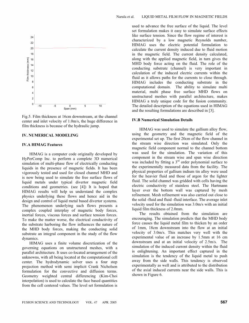
free surface. By recording the two digital images by high
speed video and using image processing tools, the vertical
movement of the laser light line and hence the location of
the liquid metal free surface can be accurately predicted.
Figure 1 shows the laser light sheet created by the light
sheet module, reflecting off the channel bottom. Spanning
the laser light sheet through out the test section provides
the stream wise and span wise variation of the film
thickness. The technique has potential to yield additional
information about the flow besides the film thickness,
capturing the stream wise and span wise surface waves
being one of them. The basic elements of the method have
been established and refinements are underway. Figure 2
shows a schematic of the experimental set up with the
laser light diagnostic.
Fig.2. Schematic for the experiment
III RESULTS
III.A Observations
The liquid metal film flowing under the magnetic
field set up exhibits some interesting features. The 2mm
thick film emerging from the nozzle tends to have a rapid
increase in thickness at a particular downstream location
depending on the initial inlet velocity. This sudden
increase in the fluid film thickness is known as the
hydraulic jump. The higher the initial velocity, the farther
is the location of the jump from the inlet nozzle. Also the
span wise behavior of the jump changes with the inlet
flow velocity. At low inlet velocities the hydraulic jump is
straight along the span but it gets progressively bowed in
the span wise direction as the inlet velocity is increased.
The span wise curvature of the discontinuity shows that
the average fluid velocity close to the walls is higher than
in the core indicating the presence of side wall jets. This
can also be observed from the direction of rotation of the
vortices that are shed close to the walls. The hydraulic
jump dissipates a large amount of flow inertia and the
flow downstream from the jump is slow and clearly
unsuitable for divertor application due to overheating
concerns. Furthermore at higher inlet velocities (2.5m/s-
Front view
Light sheet
module
HeNe laser
High speed camera
PC frame
grabber
Mirror
Laser
sheet
Liquid Metal flow
Image
processing
module
Free surface
profile
Light Sheet
FUSION SCIENCE AND TECHNOLOGY VOL. 47 APR. 2005 565
Narula et al. LIQUID METAL FILM FLOW IN MAGNETIC FIELDS

3m/s) an increasing cross sectional force is observed
manifesting in the tendency of the fluid to being pushed
away from the side walls of the conducting channel. The
wall normal magnetic field component progressively
increases downstream and causes the liquid metal stream
to pinch inward, trying to change shape to keep the linked
magnetic flux constant. Figure 3 shows this effect for an
inlet velocity of 3.0m/s with and without the applied
magnetic field. The magnetic field is applied
perpendicular to the bottom wall. This pinching in effect
leads to separation zones or bare spots where the liquid
has completely pulled away from the wall. This effect is
observed in the numerical simulation as well and will be
discussed ahead. Attempts are being made to diagnose
and extract quantitative information from the observed
phenomenon. As a first step, the liquid metal film
thickness has been obtained at a particular downstream
location for different values of the inlet velocity.
Fig.3. Top shows liquid behavior at 3.0m/s with the
magnetic field, the dominant magnetic field component
points out of the plane of the paper. Bottom shows the
same inlet velocity but without an applied magnetic field.
III.B Results
For quantification of the film thickness, the laser light
line was set up at 16cm downstream from the inlet nozzle
and made to fall symmetrically about the channel center,
covering a span wise length of 3cm. Inlet velocity was set
at 1.0m/s, 1.5m/s, 2.0m/s and 2.5m/s. For the first two
inlet velocity conditions, the measurement location lies
downstream of the hydraulic jump, while for the higher
inlet velocities, the measurement location is upstream of
the jump. Comparing the film thickness for the different
inlet velocity cases, give us an order of magnitude of the
difference in the film thickness before and after the
hydraulic jump. At higher inlet velocities, (2.5-3.0m/s) a
large part of the flow domain lies upstream of the
hydraulic jump and we can observe the flow thickening
taking place purely on account of the opposing MHD
body forces. The typical increase in the film thickness at
16cm downstream for the inlet velocity range 2.0m/s-
3.0m/s is of the order of 1mm-2mm. For the velocity
range 1.0m/s-2.0m/s, the hydraulic jump occurs close to
the inlet nozzle and most of the flow domain lies
downstream of the jump, the typical film thickness
increase observed for this case is an order of magnitude
higher and lies at 18mm-20mm. Figures 4 and 5 show the
film height evaluation for the two scenarios with and
without the hydraulic jump at the measurement location.
Liquid pushed away
Span (mm)
Film
Thickness(mm)
-10 -5 0 5 100
0.5
1
1.5
2
2.5
3
3.5
4
No wall detachment
Fig.4. Film thickness at 16cm downstream, at the channel
center and inlet velocity of 2.5m/s
566 FUSION SCIENCE AND TECHNOLOGY VOL. 47 APR. 2005
Narula et al. LIQUID METAL FILM FLOW IN MAGNETIC FIELDS
Span (mm)
Film
thickness(mm)
-10 -5 0 5 100
2
4
6
8
10
12
14
16
18
20
22
24
Fig.5. Film thickness at 16cm downstream, at the channel
center and inlet velocity of 1.0m/s, the huge difference in
film thickness is because of the hydraulic jump.
IV. NUMERICAL MODELING
IV.A HIMAG Features
HIMAG is a computer code originally developed by
HyPerComp Inc. to perform a complete 3D numerical
simulation of multi-phase flow of electrically conducting
liquids in the presence of magnetic fields. It has been
vigorously tested and used for closed channel MHD and
is now being used to simulate the free surface flows of
liquid metals under typical divertor magnetic field
conditions and geometries. (see [4]) It is hoped that
HIMAG results will help us understand the complex
physics underlying these flows and hence aid in the
design and control of liquid metal based divertor systems.
The phenomenon underlying such flows presents a
complex coupled interplay of magnetic body forces,
inertial forces, viscous forces and surface tension forces.
To make the matter worse, the electrical conductivity of
the substrate harboring the flow influences the nature of
the MHD body forces, making the conducting solid
substrate an integral component in the study of the flow
dynamics.
HIMAG uses a finite volume discretization of the
governing equations on unstructured meshes, with a
parallel architecture. It uses co-located arrangement of the
unknowns, with all being located at the computational cell
center. The hydrodynamic solver uses a four step
projection method with semi implicit Crank Nicholson
formulation for the convective and diffusion terms.
Geometry weighted central differencing (Kim-Choi
interpolation) is used to calculate the face based quantities
from the cell centered values. The level set formulation is
used to advance the free surface of the liquid. The level
set formulation makes it easy to simulate surface effects
like surface tension. Since the flow regime of interest is
characterized by a low magnetic Reynolds number,
HIMAG uses the electric potential formulation to
calculate the current density induced due to fluid motion
in the magnetic field. The current density calculated,
along with the applied magnetic field, in turn gives the
MHD body force acting on the fluid. The role of the
conducting substrate (channel) is very important in
calculation of the induced electric currents within the
fluid as it allows paths for the currents to close through.
HIMAG includes the conducting substrate in the
computational domain. The ability to simulate multi
material, multi phase free surface MHD flows on
unstructured meshes with parallel architecture, makes
HIMAG a truly unique code for the fusion community.
The detailed description of the equations used in HIMAG
and the resulting formulations are described in [3].
IV.B Numerical Simulation Details
HIMAG was used to simulate the gallium alloy flow,
using the geometry and the magnetic field of the
experimental set up. The first 20cm of the flow channel in
the stream wise direction was simulated. Only the
magnetic field component normal to the channel bottom
was used for the simulation. The variation of this
component in the stream wise and span wise direction
was included by fitting a 3rd order polynomial surface to
the experimentally measured data from the facility. The
physical properties of gallium indium tin alloy were used
for the heavier fluid and those of argon for the lighter
fluid. The solid channel was gridded with cells having the
electric conductivity of stainless steel. The Hartmann
layer over the bottom wall was captured by mesh
refinement. Mesh refinement was also carried out close to
the solid -fluid and fluid -fluid interface. The average inlet
velocity used for the simulation was 3.0m/s with an initial
liquid film thickness of 2.0mm.
The results obtained from the simulation are
encouraging. The simulation predicts that the MHD body
force causes the liquid metal film to thicken by an order
of 1mm, 18cm downstream into the flow at an initial
velocity of 3.0m/s. This matches very well with the
experimental value of an increase by 1.5mm at 16 cm
downstream and at an initial velocity of 2.5m/s. The
simulation of the induced current density within the fluid
is enlightening. An important effect captured in the
simulation is the tendency of the liquid metal to push
away from the side walls. This tendency is observed
experimentally as well and is attributed to the distribution
of the axial induced currents near the side walls. This is
shown in Figure 6.
FUSION SCIENCE AND TECHNOLOGY VOL. 47 APR. 2005 567
Narula et al. LIQUID METAL FILM FLOW IN MAGNETIC FIELDS

0
0.005
Z
0
0.05
0.1
0.15
0.2
X
-0.1
-0.05
0
0.05
0.1
Y
X
Y
Z
Fig.6. Free surface of liquid metal obtained from the
simulation. The liquid is pushed away from the side walls,
flow occurs in the ‘X’ direction. Stream wise flow
thickening can also be seen.
Further improvement in the modeling effort will be
valuable. The current numerical method cannot capture
the hydraulic jump observed at low inlet velocities, which
might become an important issue for designing the
operational regime that avoids jumps. The current
simulation used only a single component magnetic field,
perpendicular to the bottom wall; the complete three
component magnetic field will warrant a better simulation
of the real flow. Improvements in the numerical methods
for the hydrodynamic flow solver and addition of more
cells in the computational domain for better resolution can
help provide more accurate and stable solution. All these
issues will be taken into consideration in the near future.
V. CLOSURE
Flowing liquid metal streams may form the ideal
plasma contact surfaces for the high power density plasma
facing components like the divertor, hence the study of
fast flowing liquid metal streams in fusion relevant
magnetic fields forms a very interesting and lucrative
subject for the fusion community. The bane of the concept
is the flow disrupting MHD body force acting on the fluid
as it flows through the magnetic field. The flow of liquid
gallium in a straight conducting channel with reproduced
NSTX divertor region magnetic field conditions was
studied. At low inlet velocities (1m/s-1.5m/s) a strong
hydraulic jump close to the inlet nozzle causes a slow
moving thick liquid film to fill up the channel. Though
the bottom substrate is well protected in this scenario, the
slow moving film might not be able to withstand the huge
heat flux pounding on the surface. At high inlet velocities
(2.5m/s-3.0m/s) the hydraulic jump location moves
downstream the channel but a strong tendency of the fluid
to move away from the side walls is observed. This
pinching in of the fluid from the side walls causes bare
spots on the channel bottom that beats the purpose of
substrate protection. Further experiments with more
realistic divertor geometries and configurations and a
more representative magnetic field environment are
planned to obtain additional insights into the flow
behavior.
Future work in numerical simulations is aimed at
improving the stability of the numerical technique being
used, carrying out a complete channel, complete magnetic
field simulation and establishing the effect of the different
variables like the channel conductivity, channel width,
magnetic field orientation, inclusion of gravity force etc
on the flow behavior with a view to identify the design
constraints for the development of real liquid metal PFC
systems. Since HIMAG features an unstructured grid
formulation, it is possible to use the code to simulate flow
in complex toroidal geometries like the NSTX divertor
and these simulations will be carried out once sufficient
confidence and experience has been built with simple
geometries.
ACKNOWLEDGEMENT
The authors wish to acknowledge the much needed
assistance given by Dr. Neil Morley, Dr. Mingjiu Ni, Dr.
Reza Miraghaie, Dr. Ramakanth Munipalli, Tom
Sketchley and Jonathan Burris.
REFERENCES
[1] M. NARULA, et. al., “Study of liquid metal film
flow characteristics under fusion relevant
magnetic field conditions,” Proc. 20th
IEEE/NPSS Symposium on Fusion Energy(SOFE), San Diego, California, 14-17 October,
2003, pp 2-5, IEEE.
[2] A. YING, et. al., “Exploratory studies of flowing
metal divertor options for fusion relevant
magnetic fields in the MTOR facility,” FusionEngineering and Design, 72, 35 (2004)
[3] N.B. MORLEY, et. al., “Progress on modeling
of liquid metal, free surface, MHD flows for
fusion liquid walls,” Fusion Engineering and
Design, 72, 3 (2004)
[4] R. MUNIPALLI, et. al., “Development of a 3D
incompressible free surface MHD computational
environment for arbitrary geometries: HIMAG”,
DOE SBIR Phase-II final report, June 2003.
568 FUSION SCIENCE AND TECHNOLOGY VOL. 47 APR. 2005
Narula et al. LIQUID METAL FILM FLOW IN MAGNETIC FIELDS


