ABAQUS for CATIA V5
Tutorials
AFC V2.5
Nader G. Zamani
University of Windsor
Shuvra Das
University of Detroit Mercy
SDC
Schroff Development Corporation
www.schroff.com
PUBLICATIONS
Copyrighted Material
Copyrighted
Material
Copyrighted Material
Copyrighted
Material
ABAQUS for CATIA V5, AFC V2.5 Tutorials 3-1
Chapter 3
Elastic-Plastic Analysis
of a Notched Plate
Copyrighted Material
Copyrighted
Material
Copyrighted Material
Copyrighted
Material
3-2 ABAQUS for CATIA V5, AFC V2.5 Tutorials
Introduction:
This tutorial is an extension of the problem described in chapter 2. The plate with a
central hole is pulled with a high load which drives the part into the plastic range. The
true stress/true strain curve is provided in tabular form for the plasticity model.
Problem Statement:
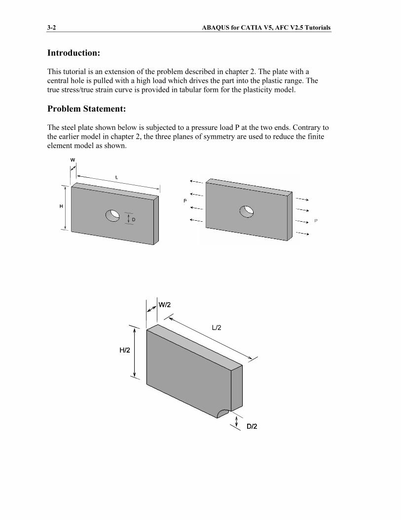
The steel plate shown below is subjected to a pressure load P at the two ends. Contrary to
the earlier model in chapter 2, the three planes of symmetry are used to reduce the finite
element model as shown.
L
H
W
D
L
H
W
D
L/2
H/2
W/2
D/2
L/2
H/2
W/2
D/2
Copyrighted Material
Copyrighted
Material
Copyrighted Material
Copyrighted
Material
Elastic-plastic Analysis of a Notched Plate 3-3
CATIA Model:
Create the CATIA model of the indicated plate with the following dimensions.
L = 0.15m, H = 0.1m, W = 0.02m, and D = 0.025m.
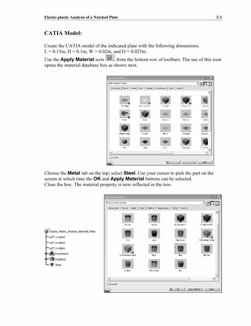
Use the Apply Material icon from the bottom row of toolbars. The use of this icon
opens the material database box as shown next.
Choose the Metal tab on the top; select Steel. Use your cursor to pick the part on the
screen at which time the OK and Apply Material buttons can be selected.
Close the box. The material property is now reflected in the tree.
Copyrighted Material
Copyrighted
Material
Copyrighted Material
Copyrighted
Material
3-4 ABAQUS for CATIA V5, AFC V2.5 Tutorials
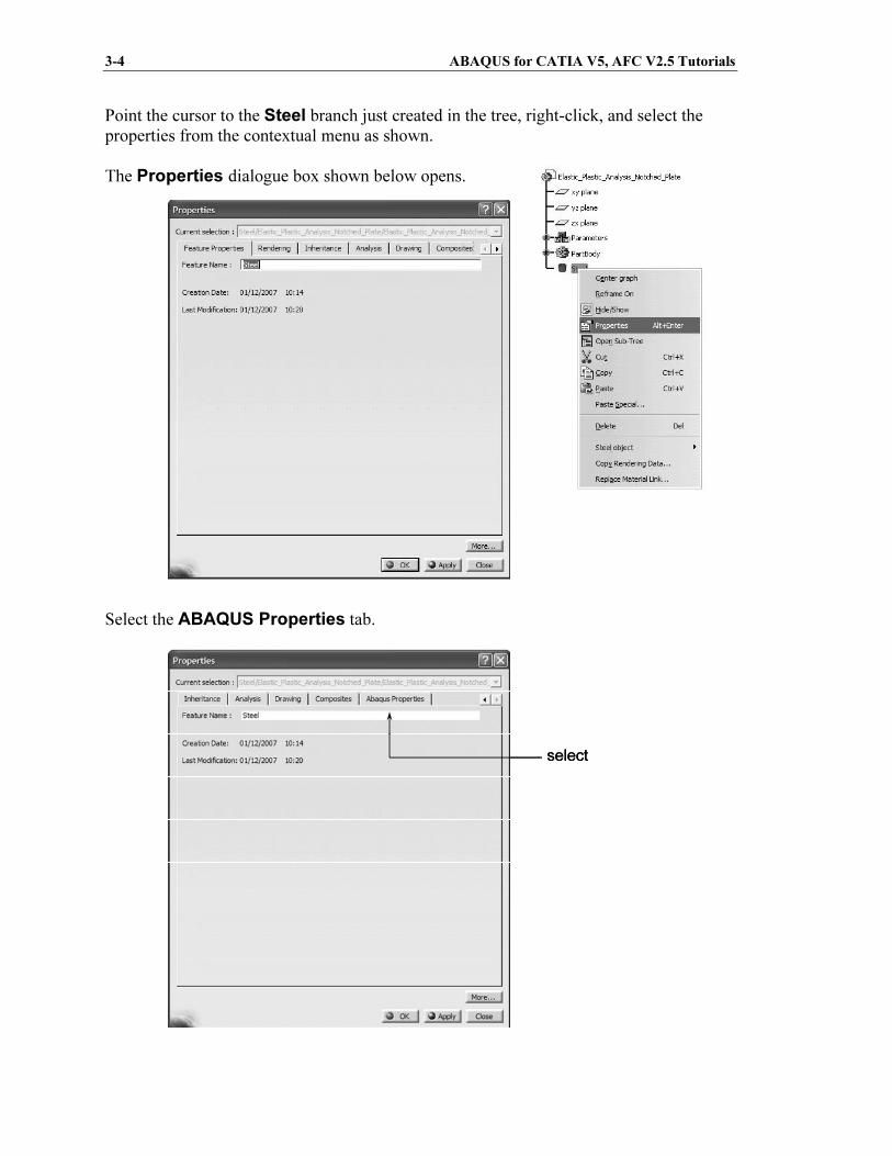
Point the cursor to the Steel branch just created in the tree, right-click, and select the
properties from the contextual menu as shown.
The Properties dialogue box shown below opens.
Select the ABAQUS Properties tab.
selectselect
Copyrighted Material
Copyrighted
Material
Copyrighted Material
Copyrighted
Material
Elastic-plastic Analysis of a Notched Plate 3-5
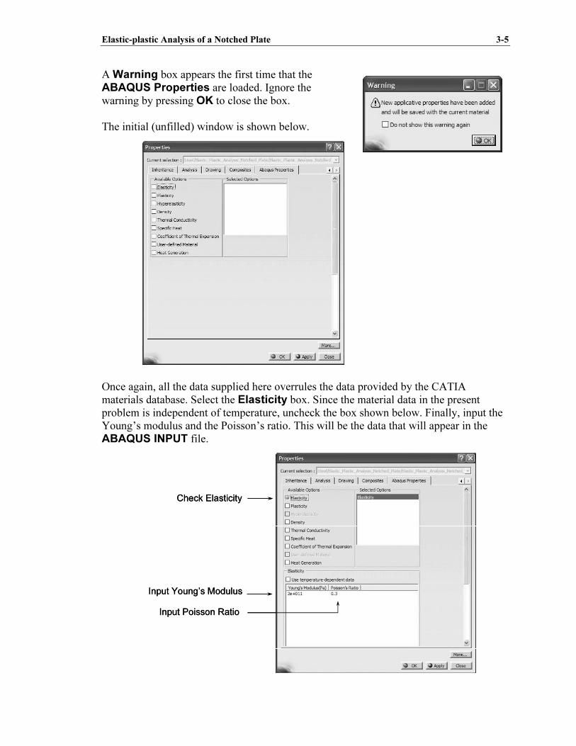
A Warning box appears the first time that the
ABAQUS Properties are loaded. Ignore the
warning by pressing OK to close the box.
The initial (unfilled) window is shown below.
Once again, all the data supplied here overrules the data provided by the CATIA
materials database. Select the Elasticity box. Since the material data in the present
problem is independent of temperature, uncheck the box shown below. Finally, input the
Young’s modulus and the Poisson’s ratio. This will be the data that will appear in the
ABAQUS INPUT file.
Check Elasticity
Input Young’s Modulus
Input Poisson Ratio
Check Elasticity
Input Young’s Modulus
Input Poisson Ratio
Copyrighted Material
Copyrighted
Material
Copyrighted Material
Copyrighted
Material
3-6 ABAQUS for CATIA V5, AFC V2.5 Tutorials
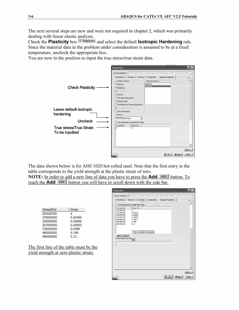
The next several steps are new and were not required in chapter 2, which was primarily
dealing with linear elastic analysis.
Check the Plasticity box and select the default Isotropic Hardening rule.
Since the material data in the problem under consideration is assumed to be at a fixed
temperature, uncheck the appropriate box.
You are now in the position to input the true stress/true strain data.
The data shown below is for AISI 1020 hot-rolled steel. Note that the first entry in the
table corresponds to the yield strength at the plastic strain of zero.
NOTE: In order to add a new line of data you have to press the Add button. To
reach the Add button you will have to scroll down with the side bar.
The first line of the table must be the
yield strength at zero plastic strain.
Check Plasticity
Uncheck
True stress/True Strain
To be inputted
Leave default isotropic
hardening
Check Plasticity
Uncheck
True stress/True Strain
To be inputted
Leave default isotropic
hardening
Copyrighted Material
Copyrighted
Material
Copyrighted Material
Copyrighted
Material
Elastic-plastic Analysis of a Notched Plate 3-7
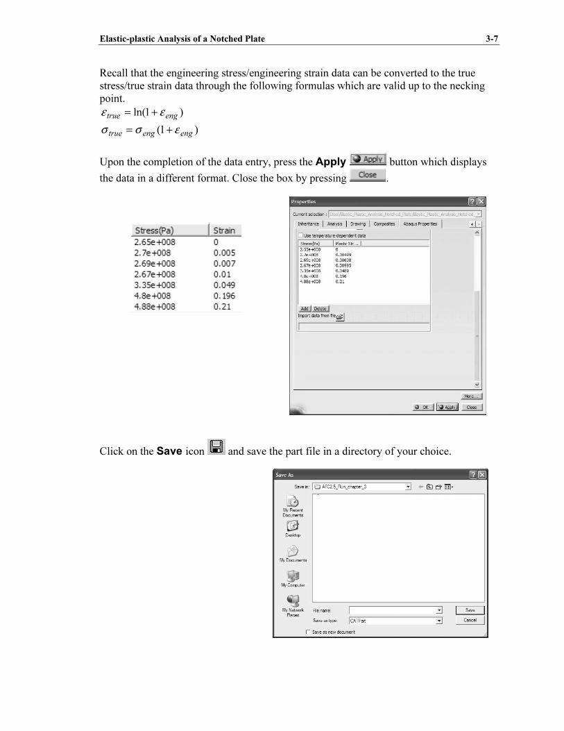
Recall that the engineering stress/engineering strain data can be converted to the true
stress/true strain data through the following formulas which are valid up to the necking
point.
)1ln( engtrue εε +=
)1( engengtrue εσσ +=
Upon the completion of the data entry, press the Apply button which displays
the data in a different format. Close the box by pressing .
Click on the Save icon and save the part file in a directory of your choice.
Copyrighted Material
Copyrighted
Material
Copyrighted Material
Copyrighted
Material
3-8 ABAQUS for CATIA V5, AFC V2.5 Tutorials
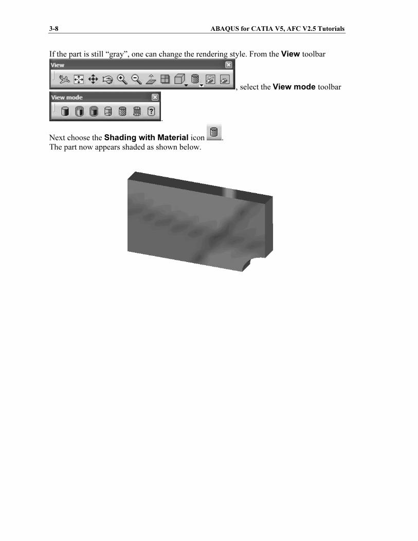
If the part is still “gray”, one can change the rendering style. From the View toolbar
, select the View mode toolbar
.
Next choose the Shading with Material icon .
The part now appears shaded as shown below.
Copyrighted Material
Copyrighted
Material
Copyrighted Material
Copyrighted
Material
Elastic-plastic Analysis of a Notched Plate 3-9
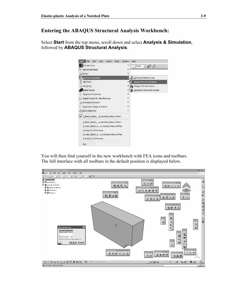
Entering the ABAQUS Structural Analysis Workbench:
Select Start from the top menu, scroll down and select Analysis & Simulation,
followed by ABAQUS Structural Analysis.
You will then find yourself in the new workbench with FEA icons and toolbars.
The full interface with all toolbars in the default position is displayed below.
Copyrighted Material
Copyrighted
Material
Copyrighted Material
Copyrighted
Material
3-10 ABAQUS for CATIA V5, AFC V2.5 Tutorials
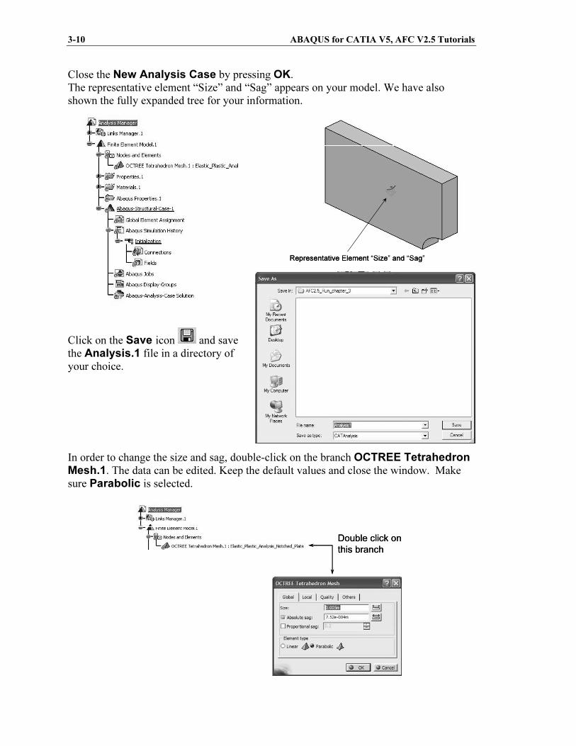
Close the New Analysis Case by pressing OK.
The representative element “Size” and “Sag” appears on your model. We have also
shown the fully expanded tree for your information.
Click on the Save icon and save
the Analysis.1 file in a directory of
your choice.
In order to change the size and sag, double-click on the branch OCTREE Tetrahedron Mesh.1. The data can be edited. Keep the default values and close the window. Make
sure Parabolic is selected.
Representative Element “Size” and “Sag”Representative Element “Size” and “Sag”
Double click on
this branch
Double click on
this branch
Copyrighted Material
Copyrighted
Material
Copyrighted Material
Copyrighted
Material
Elastic-plastic Analysis of a Notched Plate 3-11
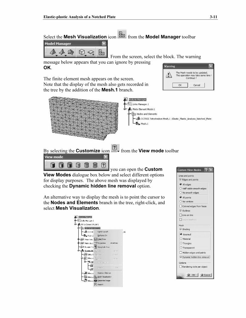
Select the Mesh Visualization icon from the Model Manager toolbar
. From the screen, select the block. The warning
message below appears that you can ignore by pressing
OK.
The finite element mesh appears on the screen.
Note that the display of the mesh also gets recorded in
the tree by the addition of the Mesh.1 branch.
By selecting the Customize icon from the View mode toolbar
you can open the Custom View Modes dialogue box below and select different options
for display purposes. The above mesh was displayed by
checking the Dynamic hidden line removal option.
An alternative way to display the mesh is to point the cursor to
the Nodes and Elements branch in the tree, right-click, and
select Mesh Visualization.
Copyrighted Material
Copyrighted
Material
Copyrighted Material
Copyrighted
Material
3-12 ABAQUS for CATIA V5, AFC V2.5 Tutorials
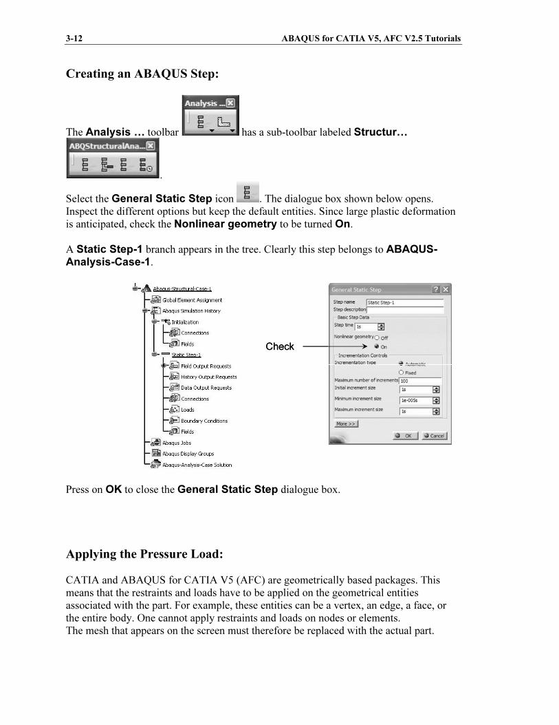
Creating an ABAQUS Step:
The Analysis … toolbar has a sub-toolbar labeled Structur…
.
Select the General Static Step icon . The dialogue box shown below opens.
Inspect the different options but keep the default entities. Since large plastic deformation
is anticipated, check the Nonlinear geometry to be turned On.
A Static Step-1 branch appears in the tree. Clearly this step belongs to ABAQUS-Analysis-Case-1.
Press on OK to close the General Static Step dialogue box.
Applying the Pressure Load:
CATIA and ABAQUS for CATIA V5 (AFC) are geometrically based packages. This
means that the restraints and loads have to be applied on the geometrical entities
associated with the part. For example, these entities can be a vertex, an edge, a face, or
the entire body. One cannot apply restraints and loads on nodes or elements.
The mesh that appears on the screen must therefore be replaced with the actual part.
CheckCheck
Copyrighted Material
Copyrighted
Material
Copyrighted Material
Copyrighted
Material
Elastic-plastic Analysis of a Notched Plate 3-13
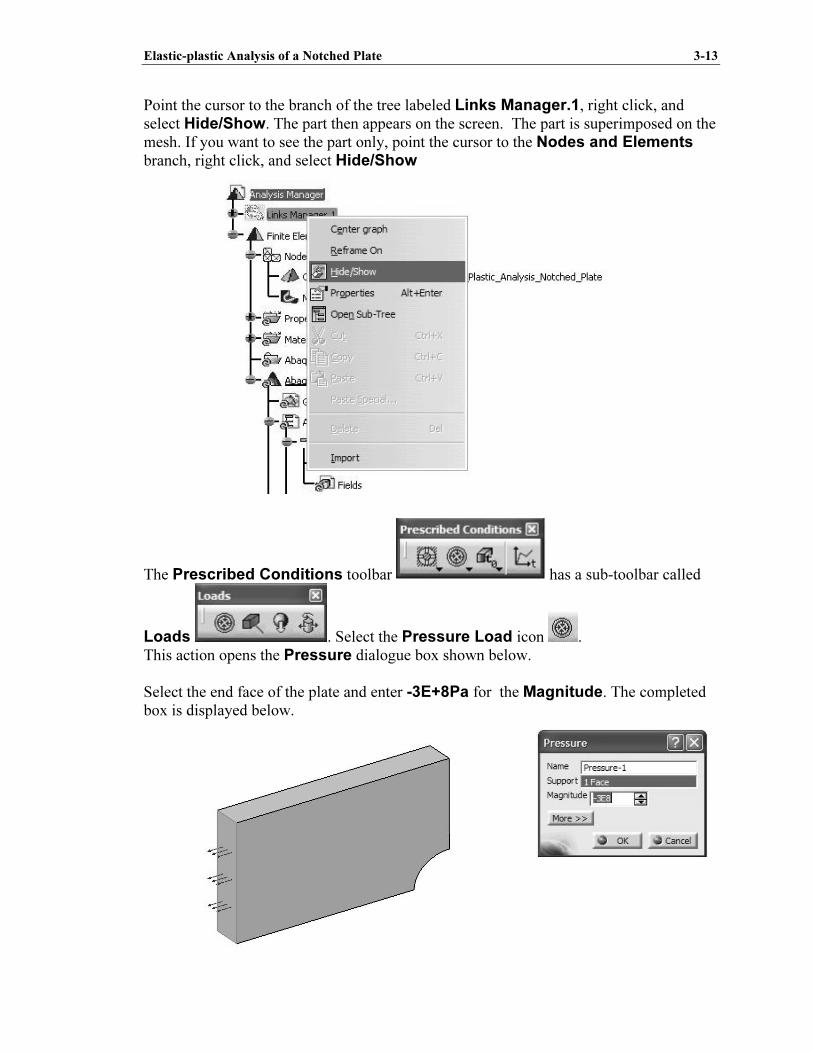
Point the cursor to the branch of the tree labeled Links Manager.1, right click, and
select Hide/Show. The part then appears on the screen. The part is superimposed on the
mesh. If you want to see the part only, point the cursor to the Nodes and Elements
branch, right click, and select Hide/Show
The Prescribed Conditions toolbar has a sub-toolbar called
Loads . Select the Pressure Load icon .
This action opens the Pressure dialogue box shown below.
Select the end face of the plate and enter -3E+8Pa for the Magnitude. The completed
box is displayed below.
Copyrighted Material
Copyrighted
Material
Copyrighted Material
Copyrighted
Material
3-14 ABAQUS for CATIA V5, AFC V2.5 Tutorials
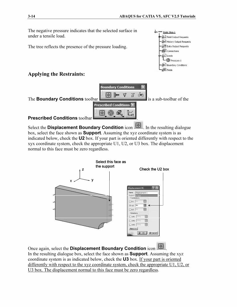
The negative pressure indicates that the selected surface in
under a tensile load.
The tree reflects the presence of the pressure loading.
Applying the Restraints:
The Boundary Conditions toolbar is a sub-toolbar of the
Prescribed Conditions toolbar .
Select the Displacement Boundary Condition icon . In the resulting dialogue
box, select the face shown as Support. Assuming the xyz coordinate system is as
indicated below, check the U2 box. If your part is oriented differently with respect to the
xyx coordinate system, check the appropriate U1, U2, or U3 box. The displacement
normal to this face must be zero regardless.
Once again, select the Displacement Boundary Condition icon .
In the resulting dialogue box, select the face shown as Support. Assuming the xyz
coordinate system is as indicated below, check the U3 box. If your part is oriented
differently with respect to the xyz coordinate system, check the appropriate U1, U2, or
U3 box. The displacement normal to this face must be zero regardless.
yx
z Check the U2 box
Select this face as
the support
yx
z Check the U2 box
Select this face as
the support


