
AbstractMechanical Inspection and Survey
Steven Seiler, NSLS-II Project
The Survey and Alignment Group is often the first and last to work with the Storage Ring magnets. Surveyors inspect, characterize and pre-align each magnet then later record the final location of each magnet on a girder assembly. This presentation describes the Survey and Alignment work on Storage Ring magnets with emphasis in the magnet’s local coordinate system creation and pre-alignment method. *Work performed under auspices of the United States Department of Energy, under contract DE-AC02-98CH10886
1

2
Mechanical Inspection & SurveyNSLS-II Magnet Workshop
Steve Seiler
April 11, 2012

3
Outline
• Girder Inspection• Magnet Inspection
– Local Coordinate System Creation• General Sextupole• General Quadrupole• Special Quadrupole
• Magnet Fiducial Discussion• Pre-Alignment• Environmental Room

4
5
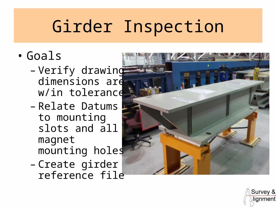
Girder Inspection
• Goals– Verify drawing
dimensions are w/in tolerance
– Relate Datums to mounting slots and all magnet mounting holes
– Create girder reference file
6
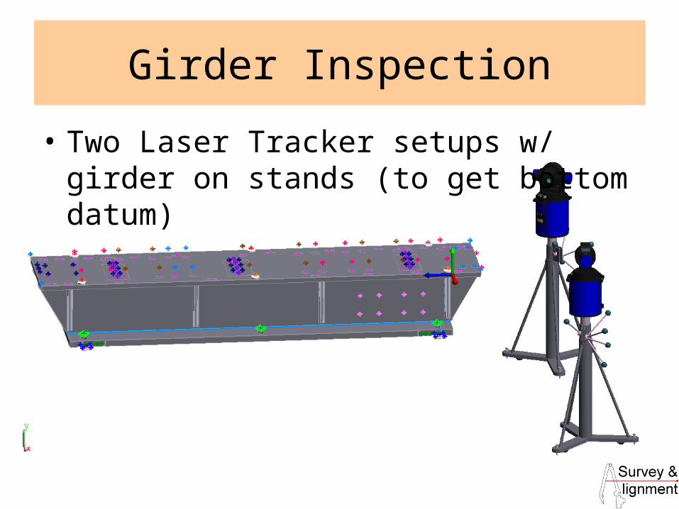
Girder Inspection
• Two Laser Tracker setups w/ girder on stands (to get bottom datum)
7
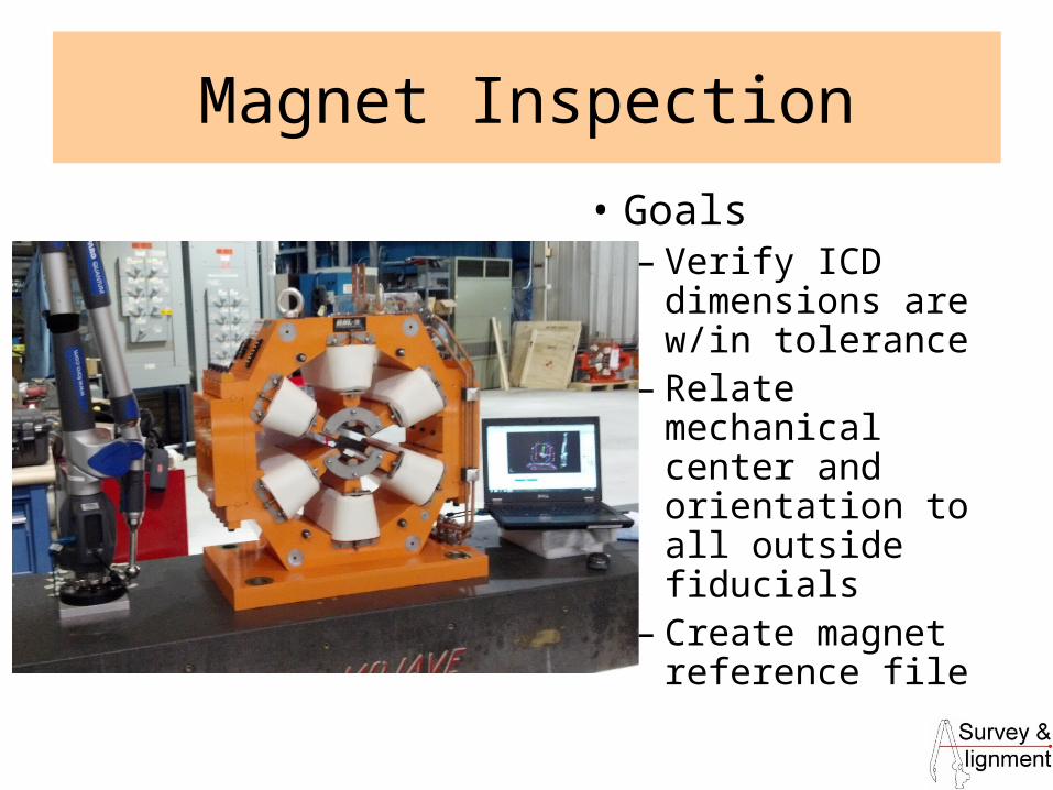
Magnet Inspection
• Goals– Verify ICD
dimensions are w/in tolerance
– Relate mechanical center and orientation to all outside fiducials
– Create magnet reference file

8
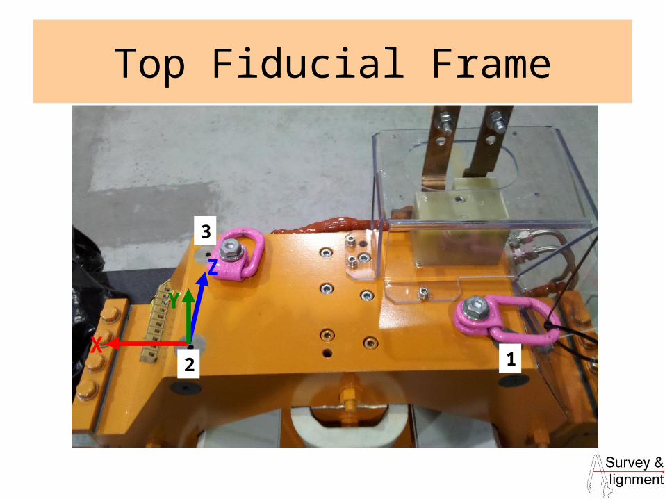
Top Fiducial Frame
• Each of the three top fiducials is measured twice using a pin nest and the 1.5” probe– Once with the CMM arm top joint upstream– Once with the CMM arm top joint downstream
• US/DS points averaged for each fiducial• Frame built such that Y is normal to the
plane of the three averaged fiducials, Z points from fiducial 2 to 3, and the origin is at fiducial 2.
9
Top Fiducial Frame
X
Y
Z
1
3
2
10
US/DS Fiducial Planes
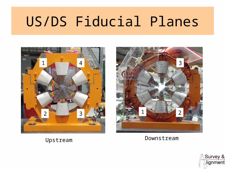
• 4 upstream and 3 downstream (most magnets) fiducials define these faces
• Each fiducial is measured with a pin nest and the 1.5” probe tip
• The dZ (with the Magnet Frame active) of the two plane centroids is the mechanical yoke length
11
US/DS Fiducial Planes
1
2 3
4
1 2
3
Upstream Downstream
12
Pole Tips (Sextupole)
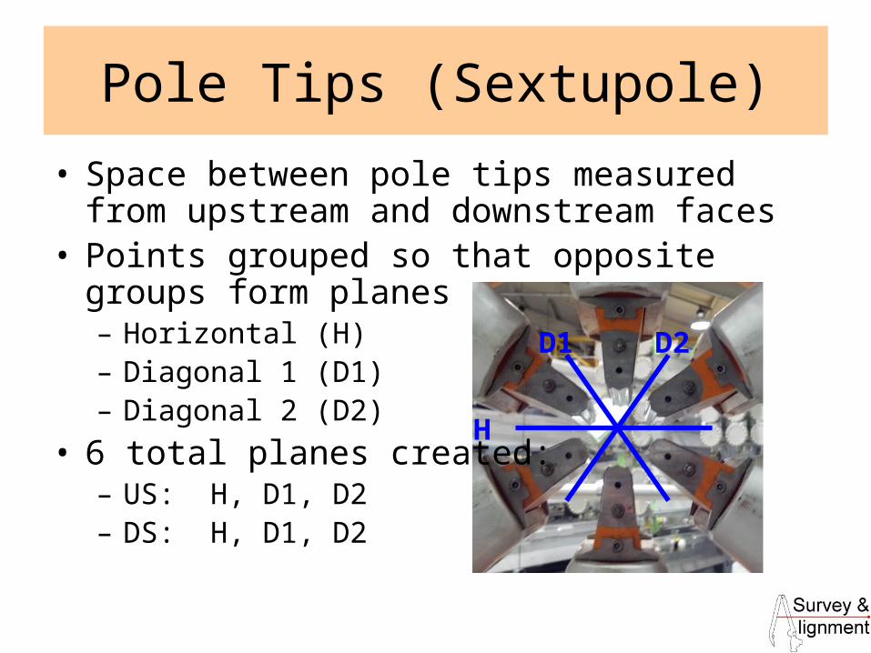
• Space between pole tips measured from upstream and downstream faces
• Points grouped so that opposite groups form planes– Horizontal (H)– Diagonal 1 (D1)– Diagonal 2 (D2)
• 6 total planes created: – US: H, D1, D2– DS: H, D1, D2
H
D1 D2
13
Pole Planes/Lines (STP)
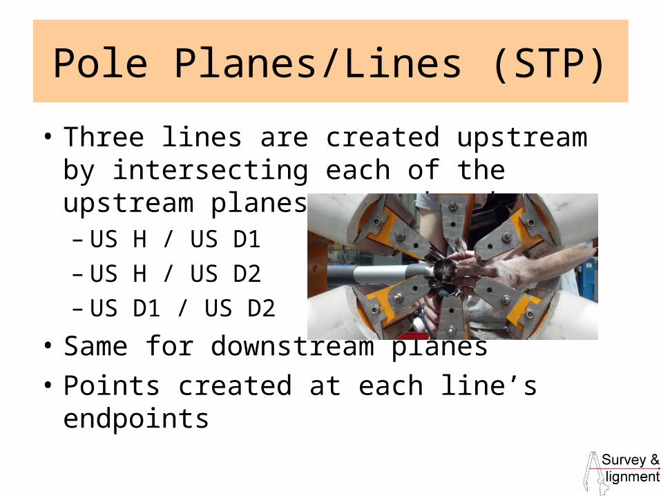
• Three lines are created upstream by intersecting each of the upstream planes to each other:– US H / US D1– US H / US D2– US D1 / US D2
• Same for downstream planes
• Points created at each line’s endpoints

14
Z Axis (STP)
2 plane intersection line
endpoints
2 plane intersection line
endpoints
US Plane DS Plane
US AVG LINE
DS AVG LINE
US US
DS US
DS DSUS DS
US DSZ AXIS
(Side View)
15
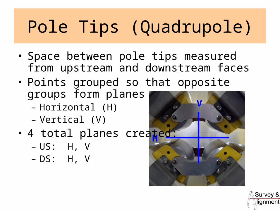
Pole Tips (Quadrupole)
• Space between pole tips measured from upstream and downstream faces
• Points grouped so that opposite groups form planes– Horizontal (H)– Vertical (V)
• 4 total planes created: – US: H, V– DS: H, V
H
V

16
Pole Planes/Lines (Quad)
• Line created upstream by intersecting the upstream planes to each other:– US H / US V
• Same for downstream planes
• Points created at each line’s endpoints
17
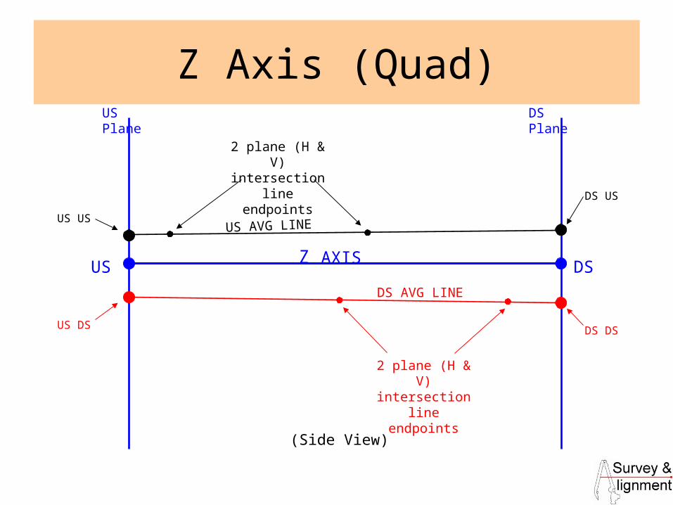
Z Axis (Quad)
2 plane (H & V) intersection line
endpoints
2 plane (H & V) intersection line
endpoints
US Plane DS Plane
US AVG LINE
DS AVG LINE
US US
DS US
DS DSUS DS
US DSZ AXIS
(Side View)
18
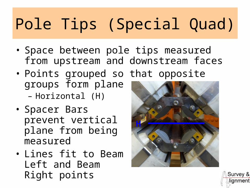
Pole Tips (Special Quad)
• Space between pole tips measured from upstream and downstream faces
• Points grouped so that opposite groups form plane– Horizontal (H)
H
• Spacer Bars prevent vertical plane from being measured
• Lines fit to Beam Left and Beam Right points
19
Pole Planes/Lines (Special Quad)
• Lines created through points measured between poles (horizontal plane)
• Points created where these lines intersect the upstream and downstream fiducial planes
• Points averaged to create endpoints for Z axis
20
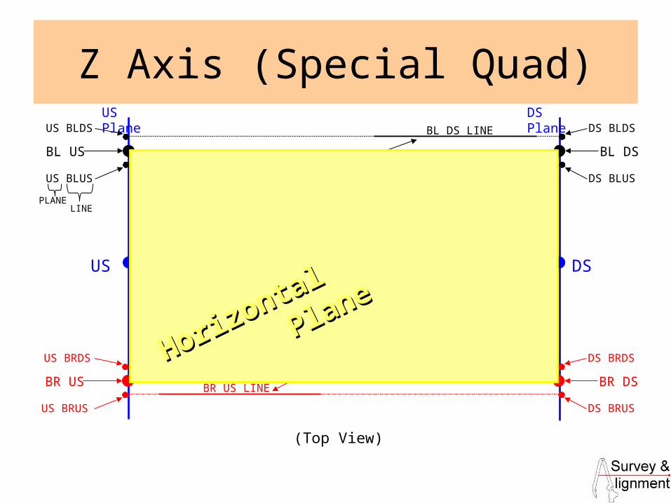
Z Axis (Special Quad)US Plane DS Plane
BL DS
US DSZ AXIS
(Top View)
US BLDS
US BLUS
DS BLDS
DS BLUS
BL US
BL DS LINE
BL US LINE
BR DS
US BRDS
US BRUS
DS BRDS
DS BRUS
BR US
BR DS LINE
BR US LINE
PLANELINE
Lines fit through measured points on
Horizontal Plane
Lines fit through measured points on
Horizontal Plane
Horizontal
Plane
Horizontal
Plane

21
Temporary Magnet Frame
• Sextupoles and General Quadrupoles:– Origin at midpoint of Z AXIS line– Primary axis: Z AXIS line defines +Z– Secondary axis: US Horizontal plane normal defines +Y– “TEMP” frame has correct Z axis, but incorrect roll (only based
on 1 pole plane out of 4 or 6)
• Special Quadrupoles:– Mechanical Frame made directly, no need for “TEMP” Frame– Origin at midpoint of Z AXIS line– Primary axis: Z AXIS line defines +Z– Secondary axis: Normal direction of plane fit through four points
• BL US, BL DS, BR US, BR DS (Intersections of BL and BR lines with US and DS planes)

22
Magnet Frame
• Sextupole: Rotate “TEMP” Frame to account for other 5 pole planes– US D1, US D2, DS H, DS D1, DS D2
• Normalize each individual deviation from nominal (divide by 6)
• Add together normalized deviations and apply this rotation (Rz) to “TEMP” to create “MECHANICAL” frame
• Quadrupole: Rotate “TEMP” Frame to account for other 3 pole planes– US V, DS H, DS V
• Normalize each individual deviation from nominal (divide by 4)
• Add together normalized deviations and apply this rotation (Rz) to “TEMP” to create “MECHANICAL” frame
23
Roll
• Mechanical roll that is reported is the relationship (Rz) of the Top Fiducial Frame and the Magnet Frame.
• Top fiducials, US/DS fiducials, and pole tips are measured within a loop. The user determines how many times to iterate the loop and an average Top Fiducial Frame and Magnet Frame is produced as well as a Magnet Frame and roll for each iteration.
24
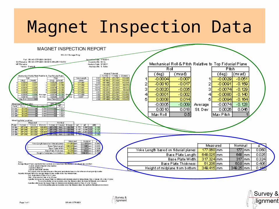
Magnet Inspection Data
25
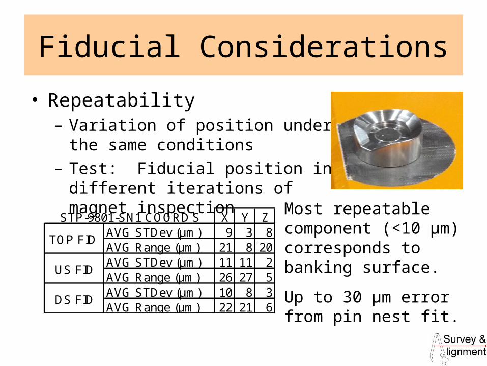
Fiducial Considerations
• Repeatability– Variation of position under the same
conditions– Test: Fiducial position in different
iterations of magnet inspection
X Y ZAVG STDev (μm) 9 3 8AVG Range (μm) 21 8 20AVG STDev (μm) 11 11 2AVG Range (μm) 26 27 5AVG STDev (μm) 10 8 3AVG Range (μm) 22 21 6
STP-9801-SN1 COORD'S
TOP FID
US FID
DS FID
Most repeatable component (<10 μm) corresponds to banking surface.
Up to 30 μm error from pin nest fit.
26
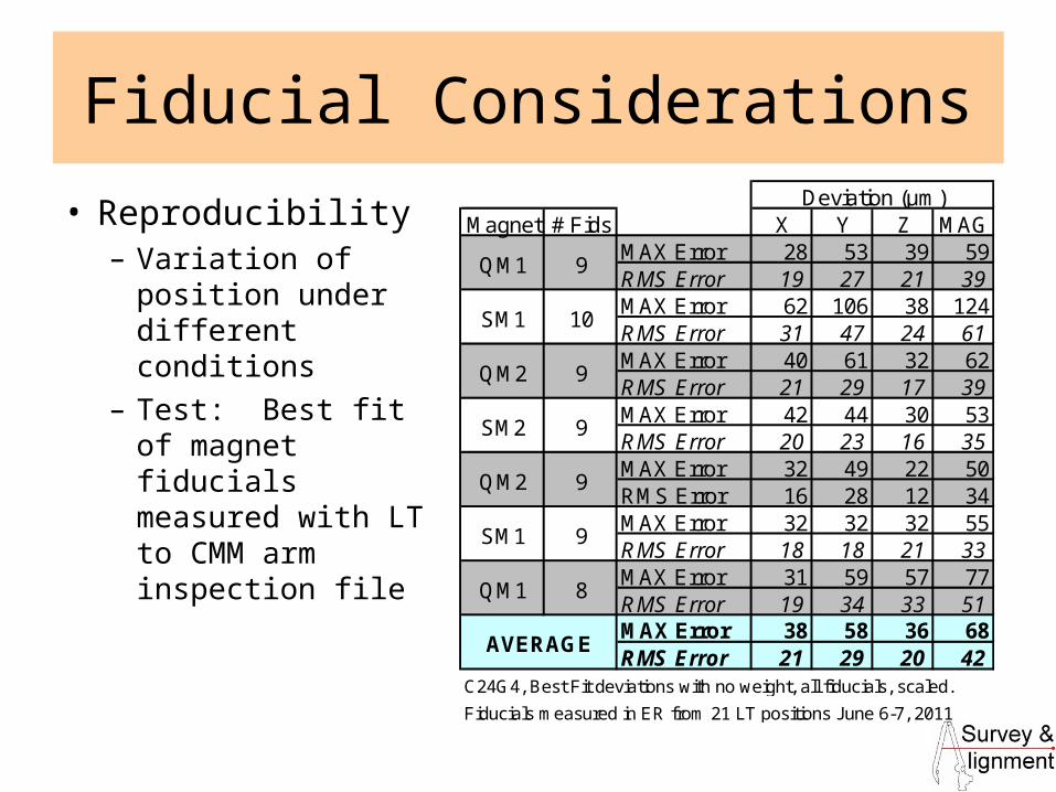
Fiducial Considerations
• Reproducibility– Variation of
position under different conditions
– Test: Best fit of magnet fiducials measured with LT to CMM arm inspection file
Magnet # Fids X Y Z MAGMAX Error 28 53 39 59RMS Error 19 27 21 39MAX Error 62 106 38 124RMS Error 31 47 24 61MAX Error 40 61 32 62RMS Error 21 29 17 39MAX Error 42 44 30 53RMS Error 20 23 16 35MAX Error 32 49 22 50RMS Error 16 28 12 34MAX Error 32 32 32 55RMS Error 18 18 21 33MAX Error 31 59 57 77RMS Error 19 34 33 51MAX Error 38 58 36 68RMS Error 21 29 20 42
Fiducials measured in ER from 21 LT positions June 6-7, 2011
C24G4, Best Fit deviations with no weight, all fiducials, scaled.
AVERAGE
9
9
9
8
SM2
QM2
SM1
QM1
Deviation (μm)
QM1
SM1
QM2
9
10
9
27
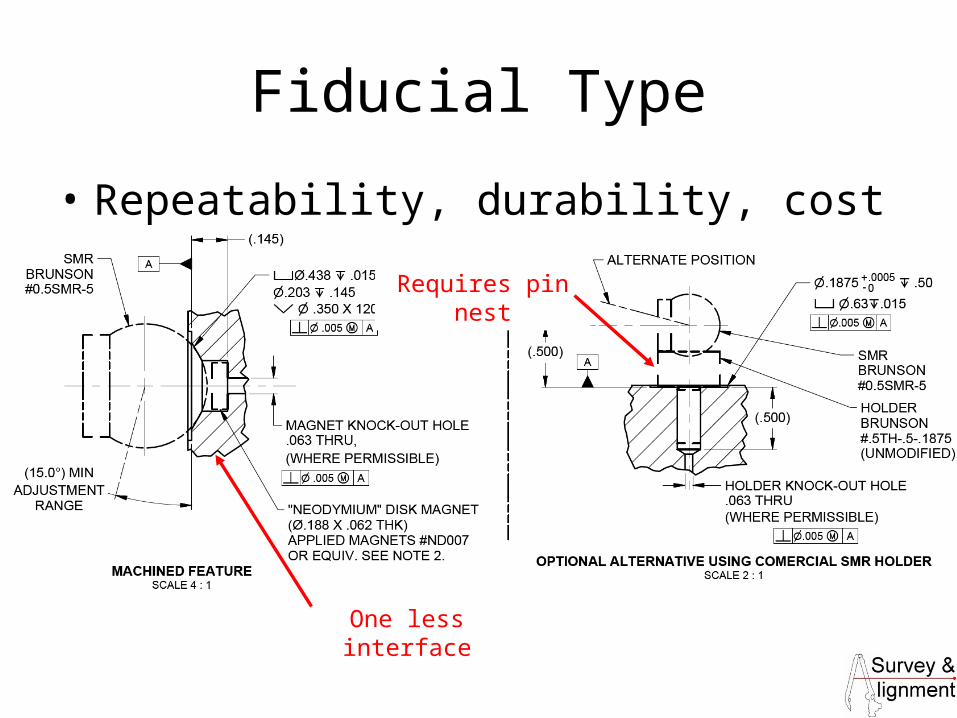
Fiducial Type
• Repeatability, durability, cost
Requires pin nest
One less interface
28
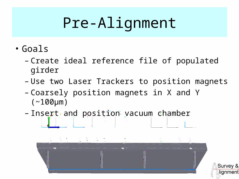
Pre-Alignment
• Goals– Create ideal reference file of populated girder– Use two Laser Trackers to position magnets– Coarsely position magnets in X and Y (~100μm)– Insert and position vacuum chamber

29
Pre-Alignment Setup
• Two granite blocks & 4 posts w/ control points• Girder stops positioned in line with girder datums•Vibrating wire position in Environmental Room is known relative to girder banking surfaces and control points in P-A
Stops
30
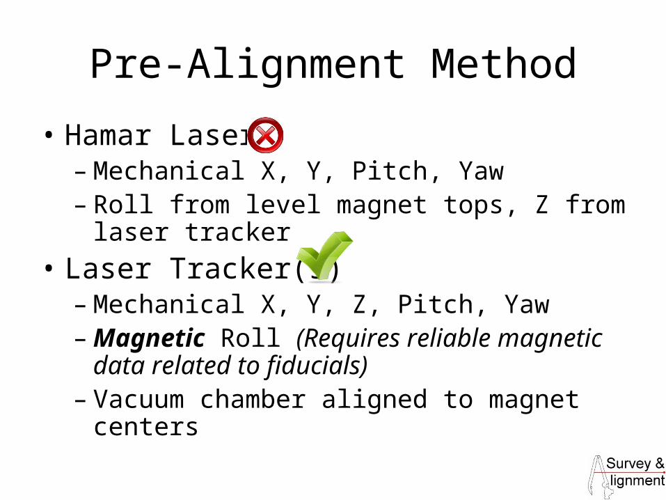
Pre-Alignment Method
• Hamar Laser– Mechanical X, Y, Pitch, Yaw– Roll from level magnet tops, Z from laser
tracker
• Laser Tracker(s)– Mechanical X, Y, Z, Pitch, Yaw– Magnetic Roll (Requires reliable magnetic
data related to fiducials)– Vacuum chamber aligned to magnet centers
31
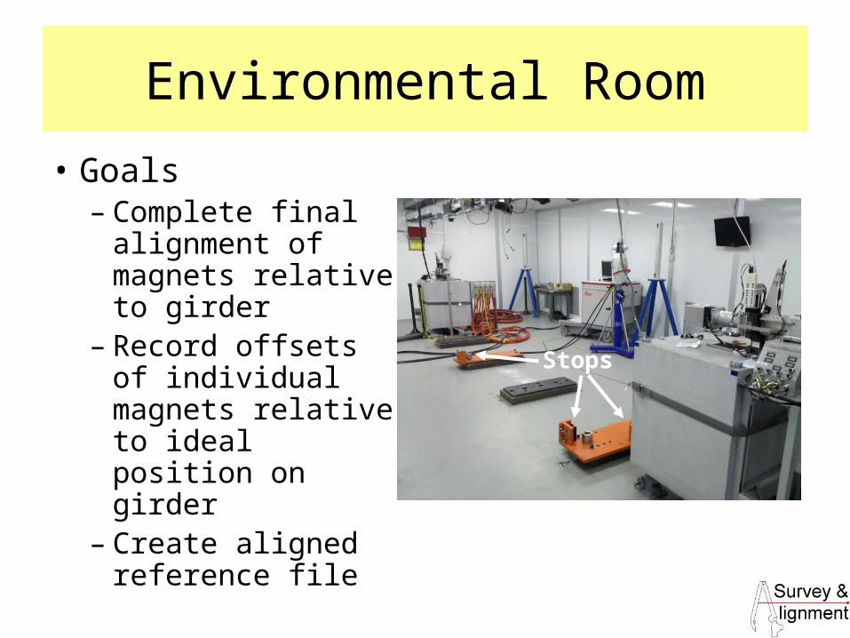
Environmental Room
• Goals– Complete final
alignment of magnets relative to girder
– Record offsets of individual magnets relative to ideal position on girder
– Create aligned reference file
Stops

32
Typical ER Procedure
• Pre-aligned, populated girder is moved to the ER• Girder is banked against stops replicating the P-A setup• Laser trackers (4 positions) are used to locate Vacuum
Chamber BPM positions relative to the wire V-notches• First run of vibrating wire shows best fit line & deviations• Magnets are moved close to the BPM line and re-
measured• Final offsets of magnets are recorded with vibrating wire
measurement• Reference of final conditions recorded by 12 laser
tracker positions

33
Aligned Reference File
• 12 Laser Tracker positions record all girder and magnet fiducials as well as all control in the Environmental Room
34
Environmental Room Data
• ΔX, ΔY– From vibrating wire
• ΔZ– From LT observations on magnet fiducials
• Roll, Pitch, Yaw– From LT observations on magnet fiducials

35
Typical ER Uncertainty
Target Ux (μm) Uy (μm) Uz (μm)Girder Fiducials 13.8 14.3 11.4Magnet Top Fiducials 14.0 14.1 11.5
URx URy URz dX (mm) dY (mm) dZ (mm) Ux (μm) Uy (μm) Uz (μm)GRD 2, 6 0.006 0.006 0.028 724 0 3150 19.6 20.2 16.1GRD 4 0.004 0.004 0.028 724 0 4572 19.6 20.2 16.1STP-9801 0.170 0.169 0.065 304 0 117 19.8 19.9 16.3QDW-9802 0.153 0.152 0.055 360 0 130 19.8 19.9 16.3QDP-9807 0.061 0.060 0.055 360 0 328 19.8 19.9 16.3
2σ Uncertainty
Approx. Inter-Fiducial Dist. Combined 2 Fid UncEst. Angular Unc (mrad)
Inter-Fiducial Distance
Combined 2 Fiducial Uncertainty
=√(U12+U2
2)
Estimated Angular Uncertainty
Roll

36
End


