Download - Accelerator Science and Technology Centre

Accelerator Science and Technology Centre
ASTeC Annual Report2004 – 2005
CCLRCRutherford Appleton Laboratory
ChiltonDIDCOT
OX11 0QX Tel: 01235 445000Fax: 01235 445808
CCLRCDaresbury Laboratory
Keckwick LaneDaresbury
WARRINGTONWA4 4AD
Tel: 01925 603000Fax: 01925 603100
CCLRCChilbolton Observatory
Drove RoadChilbolton
STOCKBRIDGESO20 6BJ
Tel: 01264 860391Fax: 01264 860142
www.cclrc.ac.uk
ASTeC Report Cover 8/12/05 2:53 pm Page 1

The Council does not accept responsibility forloss or damage arising from use of informationcontained in any of its reports or in anycommunications about its investigations.
© Council for the Central Laboratory of theResearch Councils.Enquiries about copyright and reproductionshould be addressed to:
The Librarian,CCLRC Daresbury Laboratory,Keckwick Lane,Warrington,Cheshire,WA4 4AD.
ASTeC Report Cover 8/12/05 2:53 pm Page 3

1
Accelerator Science and Technology Centre
Accelerator Science and Technology Centre
Annual Report
2004 – 2005
This report covers the work accomplished by the
Accelerator Science & Technology Centre
(ASTeC) for the financial year 2004 – 2005.
Editors: Neil Thompson and Naomi Wyles,
with help from Joe Herbert and Carl Beard.
Designed and produced by
Photographic Reprographic Services.
Daresbury Laboratory.
www.astec.ac.uk
ASTeC Annual Report_v2 8/12/05 2:48 pm Page 1
2
ASTeC Annual Report 2004 - 2005
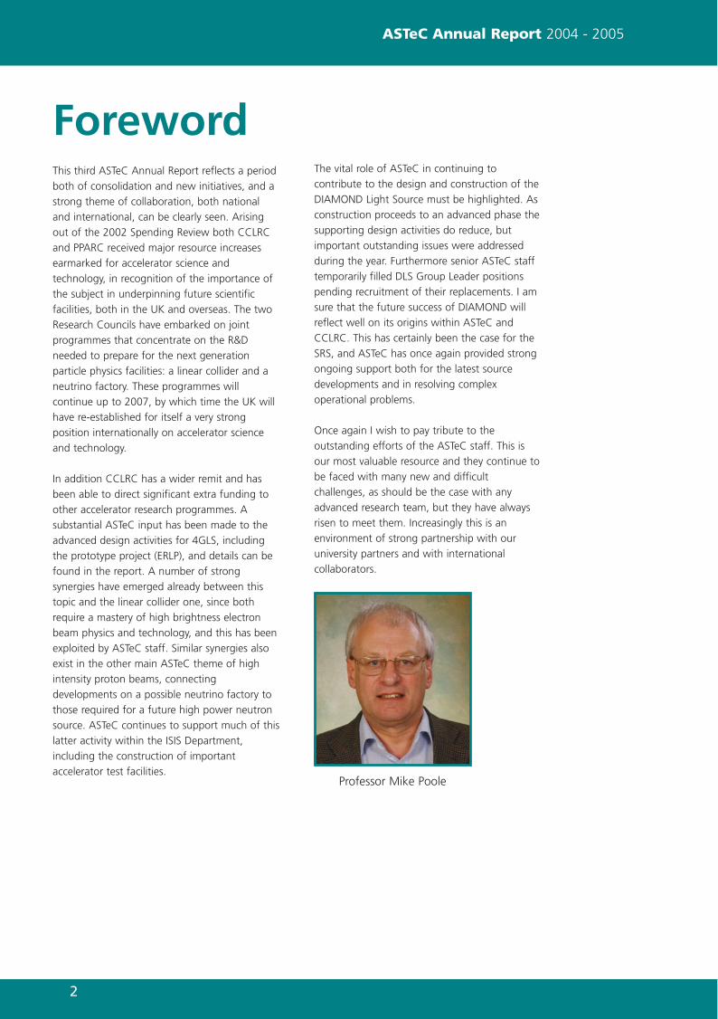
Professor Mike Poole
ForewordThis third ASTeC Annual Report reflects a period
both of consolidation and new initiatives, and a
strong theme of collaboration, both national
and international, can be clearly seen. Arising
out of the 2002 Spending Review both CCLRC
and PPARC received major resource increases
earmarked for accelerator science and
technology, in recognition of the importance of
the subject in underpinning future scientific
facilities, both in the UK and overseas. The two
Research Councils have embarked on joint
programmes that concentrate on the R&D
needed to prepare for the next generation
particle physics facilities: a linear collider and a
neutrino factory. These programmes will
continue up to 2007, by which time the UK will
have re-established for itself a very strong
position internationally on accelerator science
and technology.
In addition CCLRC has a wider remit and has
been able to direct significant extra funding to
other accelerator research programmes. A
substantial ASTeC input has been made to the
advanced design activities for 4GLS, including
the prototype project (ERLP), and details can be
found in the report. A number of strong
synergies have emerged already between this
topic and the linear collider one, since both
require a mastery of high brightness electron
beam physics and technology, and this has been
exploited by ASTeC staff. Similar synergies also
exist in the other main ASTeC theme of high
intensity proton beams, connecting
developments on a possible neutrino factory to
those required for a future high power neutron
source. ASTeC continues to support much of this
latter activity within the ISIS Department,
including the construction of important
accelerator test facilities.
The vital role of ASTeC in continuing to
contribute to the design and construction of the
DIAMOND Light Source must be highlighted. As
construction proceeds to an advanced phase the
supporting design activities do reduce, but
important outstanding issues were addressed
during the year. Furthermore senior ASTeC staff
temporarily filled DLS Group Leader positions
pending recruitment of their replacements. I am
sure that the future success of DIAMOND will
reflect well on its origins within ASTeC and
CCLRC. This has certainly been the case for the
SRS, and ASTeC has once again provided strong
ongoing support both for the latest source
developments and in resolving complex
operational problems.
Once again I wish to pay tribute to the
outstanding efforts of the ASTeC staff. This is
our most valuable resource and they continue to
be faced with many new and difficult
challenges, as should be the case with any
advanced research team, but they have always
risen to meet them. Increasingly this is an
environment of strong partnership with our
university partners and with international
collaborators.
ASTeC Annual Report_v2 8/12/05 2:48 pm Page 2

3
Contents
ASTeC Annual Report 2004 - 2005
ERLP Perfecting the Prototype 4 – 7
4GLS Touching the Grail 8 – 9
ILC Cross-border Co-operation 10 – 13
SRS Crunch Time for Apple 14 – 15
OTHER PROJECTS 16 – 19
Diamond Transformation 16
COLLABORATIONS 20 – 22
FINANCIAL SUMMARY 24
Of Mice and Men 17
Alpha Bet 18
Solving the Solvent Problem 19
Speaking the Language That Unites the World
PUBLICATIONS 23
ASTeC Annual Report_v2 8/12/05 2:48 pm Page 3
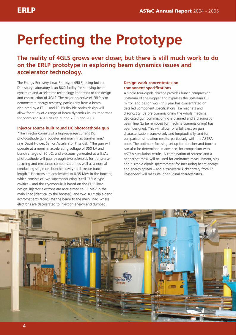
The Energy Recovery Linac Prototype (ERLP) being built at
Daresbury Laboratory is an R&D facility for studying beam
dynamics and accelerator technology important to the design
and construction of 4GLS. The major objective of ERLP is to
demonstrate energy recovery, particularly from a beam
disrupted by a FEL – and ERLP’s flexible optics design will
allow for study of a range of beam dynamics issues important
for optimising 4GLS design during 2006 and 2007.
Injector source built round DC photocathode gun “The injector consists of a high-average current DC
photocathode gun, booster and main linac transfer line,”
says David Holder, Senior Accelerator Physicist. “The gun will
operate at a nominal accelerating voltage of 350 kV and
bunch charge of 80 pC, and electrons generated at a GaAs
photocathode will pass through two solenoids for transverse
focusing and emittance compensation, as well as a normal-
conducting single-cell buncher cavity to decrease bunch
length.” Electrons are accelerated to 8.35 MeV in the booster,
which consists of two superconducting 9-cell TESLA-type
cavities – and the cryomodule is based on the ELBE linac
design. Injector electrons are accelerated to 35 MeV in the
main linac (identical to the booster), and two 180° triple-bend
achromat arcs recirculate the beam to the main linac, where
electrons are decelerated to injection energy and dumped.
Design work concentrates on component specificationsA single four-dipole chicane provides bunch compression
upstream of the wiggler and bypasses the upstream FEL
mirror, and design work this year has concentrated on
detailed component specifications like magnets and
diagnostics. Before commissioning the whole machine,
dedicated gun commissioning is planned and a diagnostic
beam line (to be removed for machine commissioning) has
been designed. This will allow for a full electron gun
characterisation, transversely and longitudinally, and for
comparison simulation results, particularly with the ASTRA
code. The optimum focusing set-up for buncher and booster
can also be determined in advance, for comparison with
ASTRA simulation results. A combination of screens and a
pepperpot mask will be used for emittance measurement, slits
and a simple dipole spectrometer for measuring beam energy
and energy spread – and a transverse kicker cavity from FZ
Rossendorf will measure longitudinal characteristics.
The reality of 4GLS grows ever closer, but there is still much work to doon the ERLP prototype in exploring beam dynamics issues andaccelerator technology.
Perfecting the Prototype
4
ERLP ASTeC Annual Report 2004 - 2005
ASTeC Annual Report_v2 8/12/05 2:48 pm Page 4

START-TO-END SIMULATIONSAdvanced accelerator and free-electron laser modelling codes
have been used to perform start-to-end ERLP simulations –
the most complete way of predicting facility performance and
confirming predictions made from analytic theory.
Start-to-end simulations unite the whole facility’s physics,
allow ERLP section interdependencies to be examined, and
model the complete electron bunch life-cycle from birth in the
gun to beam dump death, each part of the cycle being
modelled in an appropriate code.
ASTRA code chosen for electron gun modellingThe ASTRA code is chosen for electron gun modelling and
bunch transport to the end of the booster linac. This is
because ASTRA models space charge forces between
electrons - and here, where electron bunch energy is low
(<8.35 MeV), space charge forces play a significant role in
determining beam dynamics. After the booster linac,
sufficiently high electron bunch energy makes space charge
effects less significant – and ASTRA output is converted into
an input for the code Elegant, excluding space charge effects
for faster transport modelling around bends. Elegant models
electron bunch transport from the end of the booster,
through main linac acceleration, around the first arc and
through the bunch compressor to the free-electron laser.
Here, interaction between electron bunch and optical field
within the FEL cavity is modelled with the FEL code GENESIS
1.3, to help predict output radiation qualities and understand
effects of FEL interaction on the electron beam. Predicted
bunch energy profiles before and after FEL interaction agree
well with theory. Finally the output from GENESIS 1.3 is
converted back into an input for Elegant used to transport
the bunch around the second arc, through linac deceleration
to the beam dump. This is probably the first time a start-to-
end simulation has modelled a complete ERL-based FEL as far
as the beam dump, and results confirmed the beam transport
system can deliver an electron bunch to the FEL, with required
properties to allow lasing. Moreover, the disrupted bunch can
be successfully transported around the second arc and
decelerated into the beam dump with minimal losses.
CRYOGENIC ARCHITECTURE DESIGNThe ERLP currently under design will utilise TESLA-type
superconducting accelerating (SCA) cavity technology
requiring a sizable helium cryogenic liquefying plant, and the
system’s current transition from design to implementation is
being assisted by ASTeC staff. The total ERLP SCA cooling
power requirement is 180 W at 2 K, achieved by designing
5
Construction of the EnergyRecovery Linac Prototype (ERLP)
Examination of the ERLP photocathode gun
ASTeC Annual Report 2004 - 2005 ERLP
ASTeC Annual Report_v2 8/12/05 2:48 pm Page 5
two sub-component plants. A liquid nitrogen pre-cooled Linde
TCF50 Helium Refrigerator-Liquefier with a cooling capacity of
500 W at 4 K will make liquid helium – and at ambient
pressure, it will be held in a 1500 litre buffer storage Dewar
before entering the second stage of the process.
Second stage subatmospheric recuperator Stage two will comprise a subatmospheric 2 K recuperator
and distribution vessel operating at 30 mbar, requiring a large
pumping station with exacting pumping volumes. A bypass
valve feeding exhausted helium back into the pumping
system will enable fine pressure adjustments, and recuperator
pumping will be aided with a gas heater coil. Distribution of
stable subatmospheric pressure 2 K helium to SCA
applications occurs via liquid nitrogen and vacuum-shielded
transfer conduits, whilst returning helium gas is recycled into
the system to aid cooling of the forward-flow cryogenic cycle.
Finally the helium gas at ambient temperatures is recovered
into two 100 cubic metre gas storage vessels before being fed
back into the TCF50 Helium Refrigerator, via a compressor, to
re-commence the process.
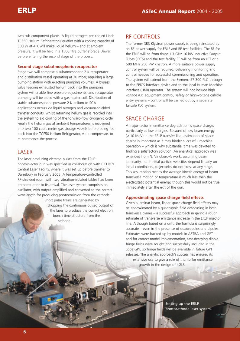
LASERThe laser producing electron pulses from the ERLP
photoinjector gun was specified in collaboration with CCLRC’s
Central Laser Facility, where it was set up before transfer to
Daresbury in February 2005. A temperature-controlled
RF-shielded room with two vibration-isolated tables had been
prepared prior to its arrival. The laser system comprises an
oscillator, with output amplified and converted to the correct
wavelength for producing photoemission from the cathode.
Short pulse trains are generated by
chopping the continuous pulsed output of
the laser to produce the correct electron
bunch time structure from the
cathode.
RF CONTROLSThe former SRS Klystron power supply is being reinstated as
an RF power supply for ERLP and RF test facilities. The RF for
the ERLP will be from three 1.3 GHz 16 kW Inductive Output
Tubes (IOTS) and the test facility RF will be from an IOT or a
500 MHz 250 kW klystron. A more suitable power supply
control system will be required, delivering monitoring and
control needed for successful commissioning and operation.
The system will extend from the Siemens S7 300 PLC through
to the EPICS interface device and to the local Human Machine
Interface (HMI) operator. The system will not include high
voltage a.c. equipment control, safety or high-voltage cubicle
entry systems – control will be carried out by a separate
failsafe PLC system.
SPACE CHARGEA major factor in emittance degradation is space charge,
particularly at low energies. Because of low beam energy
(< 10 MeV) in the ERLP transfer line, estimation of space
charge is important as it may hinder successful machine
operation – which is why substantial time was devoted to
finding a satisfactory solution. An analytical approach was
extended from N. Vinokurov’s work, assuming beam
laminarity, i.e. if initial particle velocities depend linearly on
initial coordinates, trajectories do not cross at any stage.
This assumption means the average kinetic energy of beam
transverse motion or temperature is much less than the
electrostatic potential energy, though this would not be true
immediately after the exit of the gun.
Approximating space charge field effectsGiven a laminar beam, linear space charge field effects may
be approximated by a quadrupole field defocusing in both
transverse planes – a successful approach in giving a rough
estimate of transverse emittance increase in the ERLP injector
line. Although based on a drift, the formula is surprisingly
accurate – even in the presence of quadrupoles and dipoles.
Estimates were backed up by models in ASTRA and GPT –
and for correct model implementation, fast-decaying dipole
fringe fields were sought and successfully included in the
code GPT, so fringe fields will be available in future GPT
releases. The analytic approach’s success has ensured its
extensive use to give a rule of thumb for emittance
growth in the design of 4GLS.
ERLP ASTeC Annual Report 2004 - 2005
Setting up the ERLPphotocathode laser system.
6
ASTeC Annual Report_v2 8/12/05 2:48 pm Page 6

7
MAGNETSJLAB Loan MagnetsMany ERLP transport magnets (along with the FEL wiggler)
have been generously loaned by Jefferson Laboratory where
they were used in the IR Demo free-electron laser, a machine
with many similar parameters to ERLP. Before ERLP
installation, magnets were tested to ensure they met tight
project specification tolerances, and to provide a more
detailed field map to fine-tune the computer model. Testing
(in the Insertion Device Laboratory at Daresbury) comprised
temperature tests and field mapping.
Online field measurementsAn accurate determination of the beam energy in the ERLP is
important. To measure the beam energy the beam is
deflected by a magnetic field. The field in several of the
dipoles at key points around the machine will be directly
measured as the machine is running, using specialised small
Hall probes connected into the control system. The Hall
probes are attached to the pole face of each magnet, and
calibrated against the central field. Combined with readings
from sensitive beam position monitors (BPMs), this will give
highly accurate measurements of the beam energy as it is
accelerated through the machine.
Procurement of New MagnetsRemaining magnets are being designed, manufactured and
tested by Danfysik, and ASTeC carried out preliminary
modelling using Finite Element Analysis (FEA) codes,
producing a specification giving required magnetic field
quality and maximum physical dimensions. Field quality
specification is very demanding, with magnet apertures in the
second arc being very large to allow a post-FEL electron beam
with a large energy spread to be transported without losing
electrons so as to maximise energy recovery. Aperture field
variation must also be very small because a good FEL
operation requires electron beam motion in the FEL to be
limited to within 10% of beam radius. ASTeC staff have
liaised closely with Danfysik to ensure tight specifications and
aggressive delivery schedules are satisfied.
VACUUM SCIENCEThe design of ERLP vacuum systems was completed during
2005 and work began to focus on procurement, whilst
finishing touches were made to the Beam Transport System
(BTS) design, photoinjector systems, superconducting modules
and the diagnostic beamline. Three particular challenges
occurred during the year:
The photo-injector vacuum system requires a large ceramic
insulating tube with knife-edge flanges sealed to a leak rate
better than 1x10-11 mbar.l/s. Ceramic manufacture has been a
real challenge, with the vacuum team involved in discussions
with the tube manufacturers regarding cleaning, baking,
handling and vacuum brazing. A satisfactory solution is being
actively sought.
The superconducting linac and booster modules require very
low operating pressures and clean, particle-free vacuum. By
working with module manufacturers, a satisfactory vacuum
acceptance and operating procedure has been agreed.
Control procedures include use of sub-micron particle filters
and implementation of carefully controlled pressure changes
in modules during pump-down and let-up.
Superconducting accelerating modules and the ERLP
photocathode are sensitive to particles, and two main
methods have been used to minimise numbers of particles in
ERLP vacuum systems:
• During the design phase, devices known to generate
particles have been kept to a minimum.
• Procedures were required to flush out and prevent particle
ingress into vacuum systems whilst being assembled and
installed. Procedure detailing is well under way and will be
completed in time for delivery of the first vacuum system
parts.
ASTeC Annual Report 2004 - 2005 ERLP
An ERLP quadrupole being measured on a Rotating Coilbench at the Danfysik premises near Copenhagen, Denmark.
ASTeC Annual Report_v2 8/12/05 2:48 pm Page 7

8
4GLS ASTeC Annual Report 2004 - 2005
For years, scientists have sought the holy grail of photon generation –an ultimate combination of sources delivering dynamic science to thelow energy photon science community in the UK. And now 4GLS – the 4th Generation Light Source – is within reach, destined to outstripcurrent 2nd and 3rd generation sources and lead the world in advancedphoton generation.
Touching the Grail
4GLS is a ground-breaking
proposal for a UK national
light source at Daresbury
Laboratory, and is based on
a superconducting energy
recovery linac (ERL) with high
average current photon
sources (undulators and
bending magnets) and high
peak current free electron
lasers. Key features include a
seeded high gain FEL
amplifier to generate XUV
radiation – and the prospect
of advanced research arising from unique combinations of
sources with femtosecond pulse structure. This suite of
sources must cover the whole range from THz to soft X-ray
output and be synchronised for pump-probe and dynamic
imaging studies.
4GLS - a realistic scheme capable of simulationThe proposed layout of 4GLS has moved on from its
conceptual level to a realistic scheme capable of simulation,
whilst matching users’ scientific needs. The concept
developed through early 2005, incorporating several
important new features, a 10 MeV superconducting gun
injects CW beam into a 590 MeV linac and whilst the 600
MeV output beam (at 100 mA) traverses the outer path via
undulator sources and a VUV-FEL, before returning for energy
recovery in a second pass. In parallel, a beam from a high-
charge (1 nC) RF gun operating at 1 kHz can be accelerated
to 160 MeV and then compressed before entering the high-
energy linac.
Separating 750 MeV and 600 MeV beams
The emerging 750 MeV beam is separated from the 600 MeV
beam by a fixed magnetic spreader and directed through an
alternative arc to a further variable energy linac of final
output of up to ~1 GeV. A seeded XUV-FEL is located
downstream, followed by a long undulator for high-energy
spontaneous radiation.
4GLSDARESBURY
New conceptual layout of 4GLS.
ASTeC Annual Report_v2 8/12/05 2:49 pm Page 8
9
The source portfolio is completed by an IRFEL fed from a
separate 50 MeV linac synchronised to the high-energy linacs
via their photocathode guns. At this stage, the baseline
design assumes both the inner high bunch charge loops and
outer high average current loops are based on three-bend
magnetic cells. The CW loop scheme assumes control of the
longitudinal bunch profile (through the undulators) can be
achieved without using a lumped magnetic compressor.
The control of the longitudinal dynamics would be achieved
by balancing the linac-induced correlated energy spread and
the energy-dependent path length of the particle trajectories
through the three magnet cells. This would progressively
develop the bunch profile through various undulators,
optimising the profile to ensure efficient lasing in the
VUV-FEL.
BEAM BREAKUPBeam Break Up (BBU) occurs when the beam is kicked off
course by Higher Order Modes (HOMs) contained within the
accelerating cavities – a HOM is a resonant electromagnetic
field with a higher frequency than the fundamental frequency
used to accelerate the particles. If a particle passes through
such a field off its usual axis, it will be kicked by the field and
excite the field further. If the frequency of the field is a
harmonic of the revolution frequency or the bunch frequency,
the effect can accumulate until the kick is large enough for
beam loss.
HOM growth rate dependant on beam currentHOM growth rate is also dependant on the beam current –
since the larger the current, the greater the kick. This leads to
a threshold below which the beam is stable and above which
it is likely to break up. With its short linac and low current,
BBU will not be a problem for the Energy Recovery Linac
Prototype, and work is also being carried out to ensure that
this will not be a problem for 4GLS, with two optical and two
structural methods currently being investigated.
FREE ELECTRON LASERSThis year, the work began on developing the original concept
FELs into complete designs – integrating closely with the
design of the electron beam transport systems to ensure
electron bunches delivered to the free-electron lasers have the
low emittance and energy spread required for lasing.
Covering the wide wavelength rangeThe IR-FEL challenge is to cover the widest wavelength range
whilst making allowance for optics materials and techniques
appropriate for each part of the wavelength range.
Adopting the RAFEL conceptVUV-FEL design work has led to adoption of the Regenerative
Amplifier FEL (RAFEL) concept, where optical gain over one
pass is high enough to ensure the FEL reaches saturation in a
few passes, rather than the typical several hundred passes
necessary in a low-gain oscillator FEL. Because the gain is so
high, it should be possible to use low-reflective metal mirrors
offering high resistance to radiation damage, whilst being
sufficiently reflective across the whole wavelength range of
3-10 eV. This contrasts with multilayer mirrors, which have a
relatively narrow bandwidth. The low level of optical feedback
provided by the optics is enough to significantly improve the
quality of the photon output pulse when compared to that
available from a SASE (self amplified spontaneous emission)
FEL.
FEL seeding techniqueThe XUV FEL uses a seeding technique to improve photon
pulse quality over SASE. The seed is generated by a High
Harmonic Generation (HHG) source, where a high-power
short-pulse IR laser is fired into a jet of inert gas. Electron
ionisation and recombination with nuclei generates a
high-intensity comb of harmonics, which can be filtered out
for seeding the XUV FEL at its fundamental resonant
frequency.
SPACECHARGEHaving learnt from the analysis of ERLP spacecharge effects,
the analytical approximation (due to Vinokurov) was used for
an estimate of transverse emittance growth for the 4GLS
project. The formula was tested at different energies from
those of the ERLP and also at different bunch charges - then a
small program was written to give estimates for the 4GLS
project. Detailed studies using GPT for both injector lines are
still to be undertaken, whilst an in-depth assessment of
longitudinal space charge is still ongoing. However, based on
prior ERLP experience, this is not expected to be a serious
issue.
ASTeC Annual Report 2004 - 2005 4GLS
ASTeC Annual Report_v2 8/12/05 2:49 pm Page 9

ILC ASTeC Annual Report 2004 - 2005
Work on the International Linear Collider (ILC) involves partnershipscrossing national and global boundaries, to produce a formidableworld partnership of scientific research – and ASTeC has made a strongshowing on behalf of the UK through a range of pioneering projects.
Cross-border Co-operation
RETURN OF THE DOUBLE HELIX Most people associate the double helix with DNA - butthis familiar three-dimensional shape recurs in a helicalundulator-based positron source for the ILC.
“A major challenge facing the ILC is to efficiently produce
the required positron intensity,” says Duncan Scott, Physicist,
“especially since the source must also be upgradeable so as to
produce polarised positrons.” To tackle this challenge, ASTeC
is working internationally with SLAC, DESY, Cornell, Princeton
and other centres of excellence on a proposed positron-
producing system involving an undulator magnetic device.
The undulator - 200 metres longThe undulator would be around 200 metres long and
radiation is created when the main electron beam passes
through it. The radiation hits a target where electron and
positron pairs are produced. The positrons can then be
captured and accelerated down the main positron linac. Using
polarised electron and positron beams in a future collider is a
very attractive proposition to high energy physicists because
the polarised beams will permit new physics, currently
inaccessible with unpolarised beams to be studied as well as
reducing the statistical error of the collected data.
The polarisation of electrons or positrons can be explained by
their spin, which is a quantum mechanical property
underlying all matter. Imagine the particle is a spinning sphere
like the earth, with its spin simply the axis of rotation –
though for electrons and positrons this axis of rotation can
only be positive or negative. In a 100% polarised positron
beam, all positron spins would be aligned the same way –
and for the ILC, a positron polarisation of around 60%
is required.
Measuring the magnetic fieldprofile of the permanent magnethelical undulator prototype
10
ASTeC Annual Report_v2 8/12/05 2:49 pm Page 10
11
The need for circularly polarised lightCreating a polarised positron beam requires left-or right-
handed circularly polarised light, which can be produced by a
helical undulator. The transverse magnetic fields of a helical
undulator produce a helical electron trajectory through the
device, emitting circularly polarised photons – and if you were
to look head-on at the approaching electron, you’d see it
moving in a circle, clockwise or anti-clockwise, i.e. left-handed
or right-handed. ASTeC is a member of an international
collective of institutes, working together to create a
demonstration experiment of the idea and examining two
different types of helical undulator; the first is a
superconducting bi-filar geometry with two superconducting
wires wrapped in a double helix around the vacuum vessel.
When current is passed through the wires, the longitudinal
components of the magnetic field cancel, leaving only the
required transverse helical field on the axis.
Permanent magnet technologyThe second helical undulator option is based on permanent
magnet technology, where a dipole field is created by a ring
of permanent magnet blocks, with the magnetisation vector
of each block rotated around the ring. A number of rings are
stacked together so that along a period, the dipole field is
rotated by 360 degrees. To allow access to the vacuum vessel,
the rings must be split to form top and bottom arrays.
The chosen number of blocks per ring generates the desired
field quality with the minimum magnetic force between the
two arrays. Prototypes of each device have been made and
are being assessed at Daresbury and RAL, with tests including
measurement of magnetic field profiles.
The magnetic field of the superconducting device depends
upon the amount of current flowing through the device –
and, says Duncan, “the field only increases to a certain level
before the magnet ‘quenches’ – in other words, it becomes
non-superconducting.” Measurements of when this occurs
have proved valuable in verifying computer simulations, whilst
determining the maximum possible field for the magnet.
A preferred technology recommendationWhen the test results have been analysed, a preferred
technology recommendation will be made, based on overall
magnetic performance, capital costs and design flexibility –
then a larger working prototype will be built. As well as the
magnet design of the helical undulator, work has been done
on vacuum vessel requirements – to create the highest
possible field, the aperture of the magnet needs to be a small
as possible. The limit for the electron beam is 4mm, though
achieving a vacuum in such a long narrow gap magnet is no
trivial matter.
ASTeC Annual Report 2004 - 2005 ILC
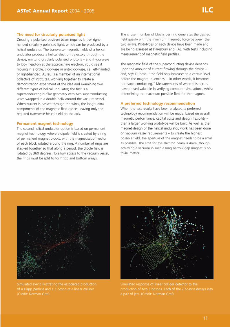
Simulated event illustrating the associated production of a Higgs particle and a Z boson at a linear collider. (Credit: Norman Graf)
Simulated response of linear collider detector to theproduction of two Z bosons. Each of the Z bosons decays intoa pair of jets. (Credit: Norman Graf)
ASTeC Annual Report_v2 8/12/05 2:49 pm Page 11
EXTRACTION, COLLIMATION,CORRECTION - COLLABORATIONInternational collaboration underlines AcceleratorPhysics work for 2004-5, which includes the 2 mradextraction line, collimation design for the linear colliderand correction of local chromaticity, which forms thebasis of the final focus design for the InternationalLinear Collider.
In August 2004, the International Technology
Recommendation Panel (ITRP) recommended using cold linac
technology for the linear collider. The bunch structure of a
cold linac allows a head-on beam collision, though the
extraction of the highly disrupted beam poses a considerable
challenge. ASTeC had been collaborating with French
laboratories LAL, Orsay and CEA, Saclay on a possible solution
to the head-on beam extraction for TESLA before the
announcement of the technology decision. After the
technology decision, it was clear that continuation of the
work was urgently required.
Small crossing angle solution to save head on physicsTo overcome the problems associated with the TESLA head-on
scheme, two solutions had been suggested for TESLA – a
small vertical crossing angle and a small horizontal crossing
angle. The latter was preferred since it had major advantages
which were head-on beam collision, it didn’t require
electrostatic separators, it required only minor crab crossing
correction and it avoided septum irradiation problems. The
first ILC workshop was held at KEK in November 2004, where
the Beam Delivery working group recommended a ‘Straw
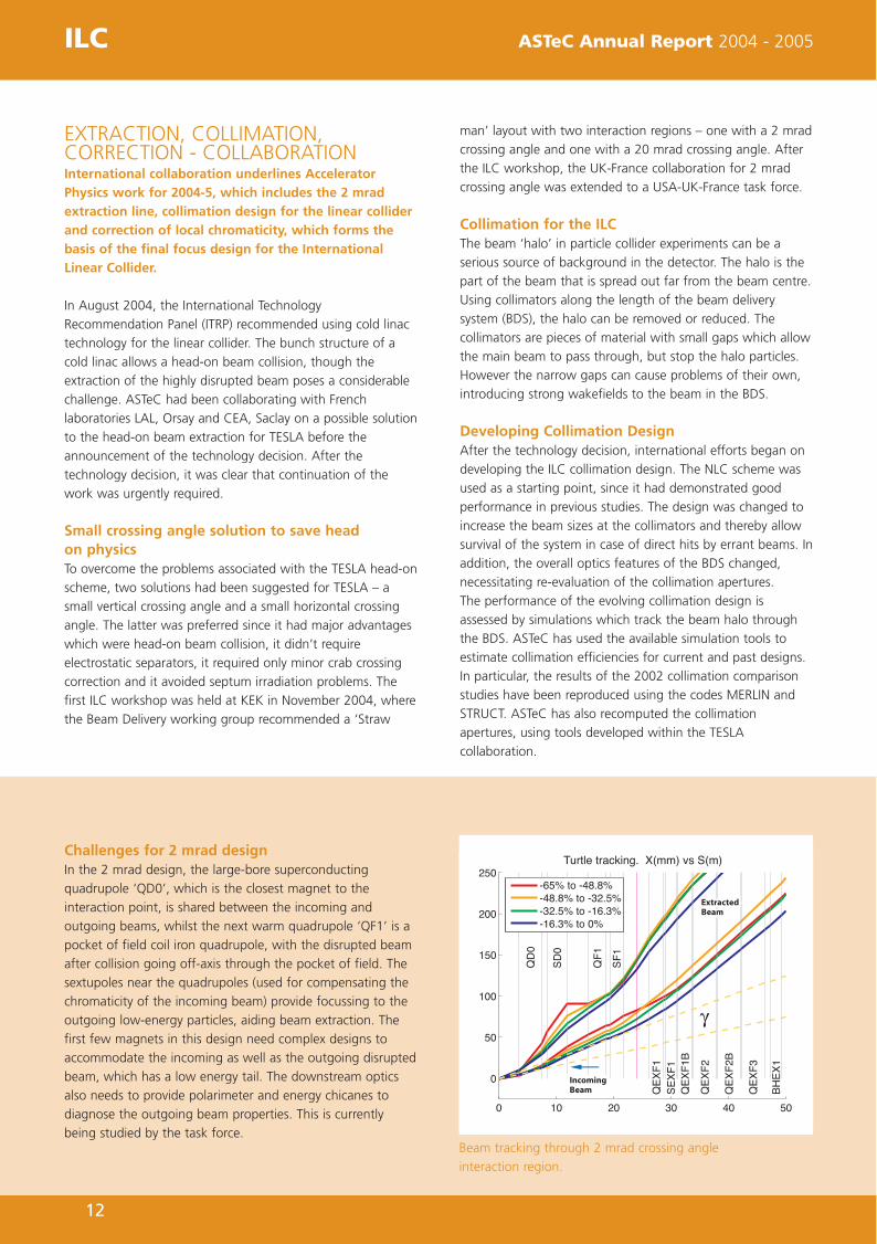
Challenges for 2 mrad designIn the 2 mrad design, the large-bore superconducting
quadrupole ‘QD0’, which is the closest magnet to the
interaction point, is shared between the incoming and
outgoing beams, whilst the next warm quadrupole ‘QF1’ is a
pocket of field coil iron quadrupole, with the disrupted beam
after collision going off-axis through the pocket of field. The
sextupoles near the quadrupoles (used for compensating the
chromaticity of the incoming beam) provide focussing to the
outgoing low-energy particles, aiding beam extraction. The
first few magnets in this design need complex designs to
accommodate the incoming as well as the outgoing disrupted
beam, which has a low energy tail. The downstream optics
also needs to provide polarimeter and energy chicanes to
diagnose the outgoing beam properties. This is currently
being studied by the task force.
man’ layout with two interaction regions – one with a 2 mrad
crossing angle and one with a 20 mrad crossing angle. After
the ILC workshop, the UK-France collaboration for 2 mrad
crossing angle was extended to a USA-UK-France task force.
Collimation for the ILCThe beam ‘halo’ in particle collider experiments can be a
serious source of background in the detector. The halo is the
part of the beam that is spread out far from the beam centre.
Using collimators along the length of the beam delivery
system (BDS), the halo can be removed or reduced. The
collimators are pieces of material with small gaps which allow
the main beam to pass through, but stop the halo particles.
However the narrow gaps can cause problems of their own,
introducing strong wakefields to the beam in the BDS.
Developing Collimation DesignAfter the technology decision, international efforts began on
developing the ILC collimation design. The NLC scheme was
used as a starting point, since it had demonstrated good
performance in previous studies. The design was changed to
increase the beam sizes at the collimators and thereby allow
survival of the system in case of direct hits by errant beams. In
addition, the overall optics features of the BDS changed,
necessitating re-evaluation of the collimation apertures.
The performance of the evolving collimation design is
assessed by simulations which track the beam halo through
the BDS. ASTeC has used the available simulation tools to
estimate collimation efficiencies for current and past designs.
In particular, the results of the 2002 collimation comparison
studies have been reproduced using the codes MERLIN and
STRUCT. ASTeC has also recomputed the collimation
apertures, using tools developed within the TESLA
collaboration.
ILC ASTeC Annual Report 2004 - 2005
Beam tracking through 2 mrad crossing angle
interaction region.
12
ASTeC Annual Report_v2 8/12/05 2:49 pm Page 12

13
Collimator wakefieldsThe ILC collimators will probably have very narrow gaps,
through which the high energy beam will pass. These narrow
gaps induce strong wakefields which disturb the beam.
Analysis of various collimator shapes is being carried out at
ASTeC with other Linear Collider Accelerator and Beam
Delivery (LC-ABD) collaborators to understand the possible
effects of geometric or resistive wall wakefields. Several
collimator designs are being considered to be tested at the
SLAC End Station A (ESA).
Verification of wakefield testsNumerical calculations are being undertaken by ASTeC with
other LC-ABD collaborators to verify these wakefield tests,
and the MAFIA simulations suite has a built-in function that
allows the user to calculate the integrated wakefield as a
function of the distance behind the source charge. This is
then used to calculate the longitudinal long range wakefield
produced by simulating a bunch through the structure. Once
these structures are better understood, suitably designed
spoilers will be recommended for the ILC.
Introducing a superconducting crab cavityOne of the interaction regions in the presently recommended
ILC straw man configuration has a large crossing angle of
20 mrad. When bunches collide with a crossing angle, there is
a loss of luminosity. Using crab cavities in the beam delivery
system, bunches are rotated to collide head-on without loss
of luminosity. ASTeC (with other LC-ABD collaborators) is
designing a crab system that provides a sufficient kick with
the necessary stability. The system is composed of a
superconducting RF crab cavity resonating at the linac
frequency or a higher harmonic, operating in the dipole
mode. Stringent control of the crab cavity phase is vital to
ensure that the bunches collide head-on.
SLAC End Station A test facility Following the cold linac technology decision, international
collaborations proposed to use ESA as a test facility for several
ILC prototypes and experiments. Of particular interest to the
UK LC-ABD project were collimation wakefield studies and
material damage studies, with each experiment requiring
different beam properties. ASTeC undertook the design of
beam optics for these experiments.
ATF2 proposal for final focus test facilityThe ILC final focus design is based on local chromaticity
correction, where chromatic aberrations generated (due to
the final doublet) are locally compensated by sextupoles near
the final quadrupole magnets. This scheme is different from
the classical method of dedicated chromaticity compensation
sections, as designed and experimentally verified for the SLAC
Linear Collider (SLC) and Final Focus Test Beam (FFTB). The
proposal to extend the Accelerator Test Facility (ATF) at KEK to
cover design and test the local chromaticity correction final
focus (ATF2) was discussed during the first ILC workshop - the
goal of ATF2 is to focus beams to a 35 nanometre vertical
beam size whilst maintaining beam stability. ASTeC
volunteered to study proposed optics designs, estimate
tolerance requirements and develop tuning procedures for
the scheme.
ASTeC Annual Report 2004 - 2005 ILC
Artist’s impression of the International Linear Collider.(Courtesy of SLAC)
ASTeC Annual Report_v2 8/12/05 2:49 pm Page 13

SRS ASTeC Annual Report 2004 - 2005
After extensive work building the new HU56 APPLE II variablepolarisation undulator, it was time for some extensive field tests toassess performance.
Crunch Time for Apple
Built in early 2004, HU56 is the new permanent
magnet-based helical undulator on Beamline 5 of the SRS.
Following completion of the construction phase, both
extensive field testing and shimming were carried out in the
Insertion Device Laboratory at Daresbury. The undulator is an
APPLE-II variable polarisation type with four permanent
magnet arrays, two of which can be moved independently
along the longitudinal direction. This allows for movement
parallel to the beam in order to vary the direction of the
field.The amount that the arrays move relative to one another
(the undulator phase) determines the polarisation of the light
produced by the electron beam travelling through the device
and it can produce horizontal, vertical, linear, or circular
polarised light, and any variation in between.
Hall probe used to generate field mapsField maps were generated at different undulator gaps and
phases using a scanning Hall probe. The resulting field map
could then be used to assess the quality of the radiation
output, together with the overall effect of the device on the
electron beam. Since the undulator is installed in a straight
section of the SRS storage ring, it must have no
overall effect on the beam direction.
The magnet blocks are not all identical, with the remanent
field strength and magnetisation direction varying minutely
from block to block. These errors can add up over the length
of the device, reducing the quality of the output radiation,
whilst having a detrimental effect on the stored beam. The
individual blocks are all magnetically tested before the device
is built, then sorted into an order that will minimise such
errors. However in a real device, some errors always remain
and these should be corrected as far as possible. Field errors
in the HU56 were corrected by swapping blocks within the
device and by 'virtual shimming' – that is, moving the blocks
up or down in small steps. There is also a small field error
component that contributes to a disturbance of the stored
beam, and this depends on the undulator's gap and phase.
It can be corrected using trim coils, that produce a small
horizontal or vertical magnetic field in addition to the
undulator's field. The currents in these coils are automatically
changed as the undulator's gap and phase are changed – and
as a result, the gap and phase can be changed at any time,
with minimal effect on the SRS stored beam.
Installation into the SRS storage ringHU56 was installed into the SRS storage ring in October 2004
and the first measurement made was its effect on the beam
without any correction. There was sufficient movement in the
position of the beam to merit correction as the gap was
closed but the effect was less than was anticipated.
The shift in the vertical tune (the rate of transverse oscillations
within the beam) was minimal and did not require correction.
Trim coil values were optimised for each setting of gap and
phase, and the settings actually required were significantly
less than the correction coils were capable of. The undulator
gap and phase were then changed and the beam position
was monitored with the trim coils switched on. The trim coils
compensated well for the effect of the undulator on the
beam, so that there was no significant movement.
HU56 undergoing Hall probe testing
14
ASTeC Annual Report_v2 8/12/05 2:49 pm Page 14
15
RESTORING THE BALANCEAfter an RF cavity loss, infrared beamlines showedlow-frequency instability – but after a range ofexperiments, a solution was found to restorebalance and order to beamline function.
LONGITUDINAL BEAM INSTABILITYFollowing the loss of one of the four RF cavities due to a
window failure, a low-frequency instability was observed on
the infrared beamlines. As machine vacuum improved, this
instability became so bad that the photon beam was unusable
for certain experiments, so the accelerator physics group
planned and carried out numerous experiments to
characterise and control this instability, which was assumed to
be longitudinal motion of the electrons in the RF bucket.
It was suggested that the instability was triggered by the
increase in the cavity voltage required to maintain the same
forward RF power when operating with three instead of four
cavities. It could also be due to the existence of the
unpowered fourth cavity (with its tuning mechanism located
at one end of its travel and disabled) in the beam.
This phenomenon had never been seen before in the twenty
five year history of the SRS, due to changes in machine
impedance (such as from the installation of the four
narrow-gap insertion device vessels)
Damping the instabilityBecause it was not initially possible to change any of these
factors, a mechanism was required that would damp the
instability. Measurements were made of dependence of the
instability amplitude and frequency on beam current, beam
energy, fill structure, octupole field, operation of the
superconducting wigglers and clearing electrode voltage.
Deliberately induced small pressure rises were measured but
no solution was forthcoming as to what could be used to
damp the instability to an acceptable level. Finally, it was
found that changing the position of the cavity tuner in the
unpowered cavity (from one end of its travel to the other)
acted as an on-off switch for the instability. Shortly after this
was discovered, the SRS was returned to four-cavity operation
– and since that time, there has been no sign of instability
recurrence.
ASTeC Annual Report 2004 - 2005 SRS
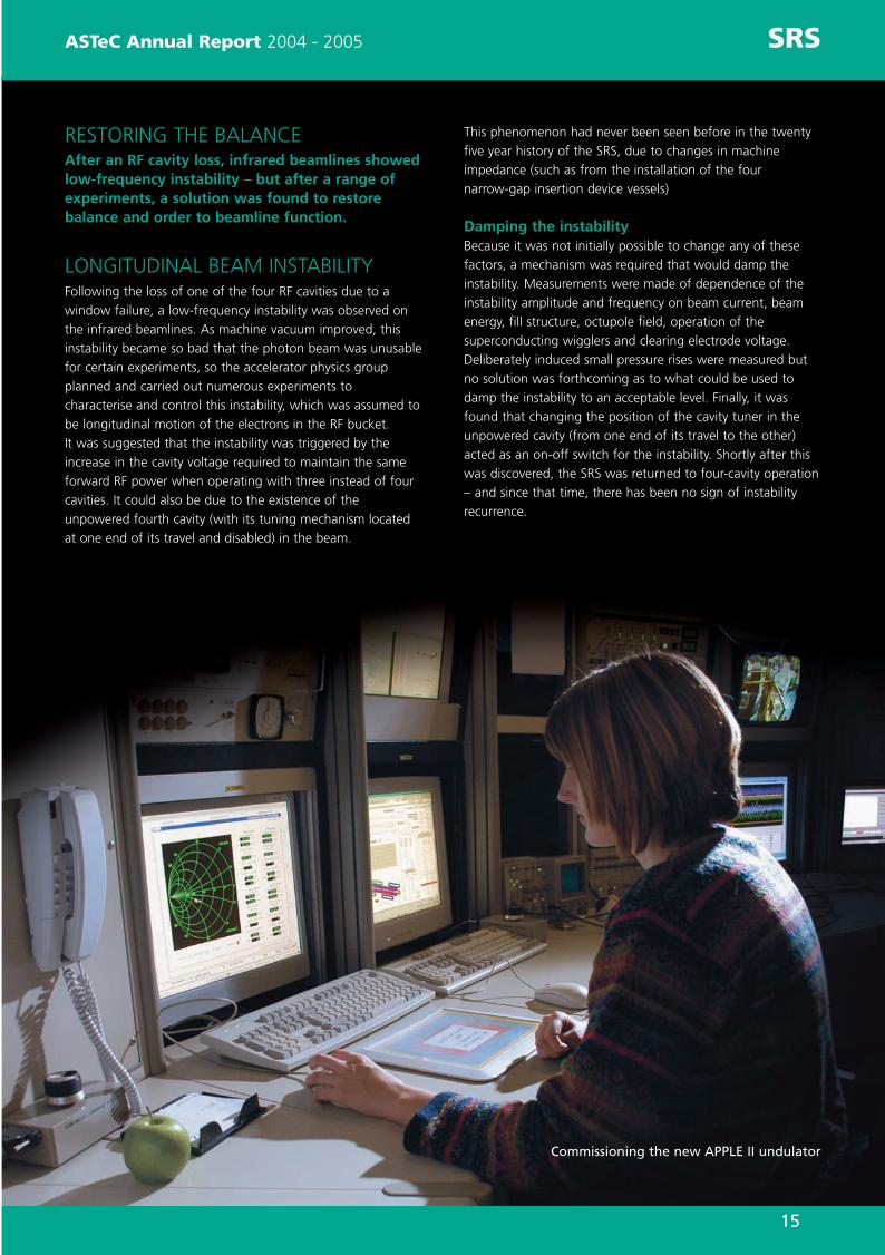
Commissioning the new APPLE II undulator
ASTeC Annual Report_v2 8/12/05 2:49 pm Page 15

16
The booster synchrotron is a highly valued part of the
machine, accelerating electrons from 100 MeV to their design
energy of 3 GeV. “Designing the booster synchrotron to
accelerate electrons without high losses ensures safe running
of the machine,” comments James Jones, Accelerator
Physicist, “so we’ve undertaken extensive studies that
involved simulating the injection of electrons into the booster
so that we could observe their evolution over time.” Errors
were included on all booster magnets to mimic real
conditions, and allowances were made for errors in other
machine areas such as the linac, which feeds electrons to the
booster - and the injection system, which is a complex
arrangement of magnets taking electrons from the linac and
inserting them into the booster.
Only a few percent electron lossesThe final analysis showed we can usually expect the booster
synchrotron to accept and accelerate electrons with only a
few percent losses (mostly at known locations where we can
contain them). “This is good news for implementing a top-up
storage ring operation,” says James. “It’s a process in which
the booster is used to regularly top up electrons circulating in
the Storage Ring for the benefit of scientific users, since
higher losses might mean too much radiation and a limitation
to operations.”
Lower electron loss inside storage ringAlthough low booster losses are important, electron losses in
the storage ring should be even lower. The ‘Booster-to-
Storage-Ring Transfer Line’ is a ~40m beam transport section
linking booster to storage ring. The line contains collimators
impinging on the electron beam, removing stray electrons
that would otherwise be lost in the storage ring. The
collimators also provide a safety mechanism to stop electrons
if anything goes wrong in the booster, protecting scientific
users and storage ring equipment.
Effective modelling of transfer line collimator systemASTeC physicists designed and modelled the transfer line
collimator system, firstly arranging the other magnets so that
collimators could be placed at locations where they would
efficiently remove out-of-position or low-energy electrons.
“The line was analysed under different likely error scenarios,
including modelling of electron-collimator interaction,”
says James. “At the same time, though, we ensured that
‘Secondary Electrons’ (created when electrons collide with
collimator surfaces), did not create a serious problem.”
The final design, and subsequent simulations, showed the
collimation system was effective in protecting the storage ring
from large electron losses – plus it could cope with
unexpected failures in upstream systems such as the booster.
Further collimation designThe other transfer line, which links the linac and booster, was
also designed with a collimator which can remove electrons
with the wrong energy for successful injection into the
booster. Again, magnets in this line were arranged so the
collimator could function effectively. The engineering designs
for both transfer lines were designed and approved so their
components can now be manufactured.
A
OTHER PROJECTS ASTeC Annual Report 2004 - 2005
As the Diamond light source facility evolves, it’s transforming andenhancing the quality of work being undertaken – especially withregard to the booster synchrotron.
Diamond Transformation
Diamond installation work
ASTeC Annual Report_v2 8/12/05 2:49 pm Page 16
17
ASTeC Annual Report 2004 - 2005 OTHER PROJECTS
The scientists working on MICE (Muon Ionisation Cooling Experiment)are intent on creating a future neutrino factory, using muon cooling tomaximise the number of muons available for neutrino production.
Of Mice and Men
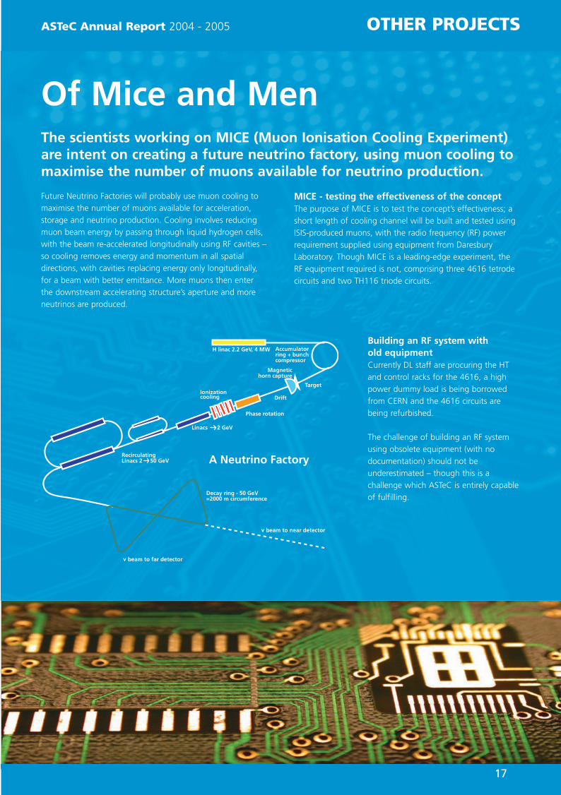
Future Neutrino Factories will probably use muon cooling to
maximise the number of muons available for acceleration,
storage and neutrino production. Cooling involves reducing
muon beam energy by passing through liquid hydrogen cells,
with the beam re-accelerated longitudinally using RF cavities –
so cooling removes energy and momentum in all spatial
directions, with cavities replacing energy only longitudinally,
for a beam with better emittance. More muons then enter
the downstream accelerating structure’s aperture and more
neutrinos are produced.
MICE - testing the effectiveness of the conceptThe purpose of MICE is to test the concept’s effectiveness; a
short length of cooling channel will be built and tested using
ISIS-produced muons, with the radio frequency (RF) power
requirement supplied using equipment from Daresbury
Laboratory. Though MICE is a leading-edge experiment, the
RF equipment required is not, comprising three 4616 tetrode
circuits and two TH116 triode circuits.
Building an RF system with old equipmentCurrently DL staff are procuring the HT
and control racks for the 4616, a high
power dummy load is being borrowed
from CERN and the 4616 circuits are
being refurbished.
The challenge of building an RF system
using obsolete equipment (with no
documentation) should not be
underestimated – though this is a
challenge which ASTeC is entirely capable
of fulfilling.
ASTeC Annual Report_v2 8/12/05 2:49 pm Page 17

18
ALPHA-X is a four-year programme to develop the emerging
technology of laser plasma wakefield acceleration – a
revolutionary concept in accelerator science – and a
collaboration between Strathclyde University, ASTeC and other
UK research groups. In a plasma wakefield accelerator, a
high-intensity laser pulse is focused in a plasma channel, into
which a short bunch of electrons is injected. The consequent
electrostatic wake produces high accelerating gradients for
the electron beam – and the aim is to produce a 1 GeV
electron beam, with a first step of 100 MeV to demonstrate
the technology. The final beam will be injected into a pair of
undulators to produce coherent FEL X-ray radiation.
The undulators have been designed by ASTeC and built at
Daresbury Laboratory. They are a permanent magnet design,
with 100 periods of 15 mm each, and a peak on-axis field of
0.7 T at the minimum gap of 5.5 mm. A slot cut into the
centre of each block allows for focusing, with the beam
confined in horizontal and vertical planes over the
device’s length.
Using a Hall Probe to obtain a field mapThe construction of the undulators is complete, and data
from the magnet block manufacturer was utilised to optimise
the order in which they were placed in the undulators. The
testing and shimming will take place in the Insertion Device
test laboratory at Daresbury, and measurements will involve a
Hall Effect probe to provide a detailed field map.
Modelling beam scattering through foil windowsASTeC performed simulation studies for the ALPHA-X
beamline design, in which the photo-injector is isolated from
the plasma channel to ensure good vacuum conditions. A thin
foil window between injector and plasma channel can achieve
this, though beam scattering through the foil may have an
adverse effect by increasing angular beam spread and beam
size, making it more difficult (or impossible) to focus to the
small spot size required at the plasma channel.
Investigations were undertaken into modelling beam
scattering effects through the foil windows, which are
particularly thin (a few microns or less), making
straightforward multiple scattering calculations inappropriate.
This is a ‘plural scattering’ phenomenon, with beam particles
experiencing a small number of scatters in the foil, whilst
some particles are not scattered at all. To calculate plural
scattering requires detailed simulation using a statistical
approach to estimate the number of scatters each particle
experiences and the deflection angle of each scatter.
Using GEANT to undertake simulationThe GEANT (GEometry ANd Tracking) code (primarily used for
high-energy particle physics studies) was used for the
simulation, and routines to calculate plural scattering were
extracted and interfaced to the existing accelerator physics
code, MERLIN, at Daresbury Laboratory, allowing for study of
the scattering effect of thin Beryllium windows (1 to 10
microns thick) on the 6 MeV ALPHA-X beam. As expected,
the simulated angular distribution of scattered beams showed
an unscattered portion and scattered ‘tails’ – with the
thinnest windows producing the smallest tails.
OTHER PROJECTS ASTeC Annual Report 2004 - 2005
For pioneering new work, ASTeC is always a good bet – as Alpha-Xproves through its revolutionary laser plasma wakefield accelerationtechnology.
Alpha Bet
Construction of an ALPHA-X undulator
ASTeC Annual Report_v2 8/12/05 2:49 pm Page 18

19
ASTeC Annual Report 2004 - 2005 OTHER PROJECTS
Neutron absorption, vacuum gauge calibration – and finding a newcleaning solvent for vacuum component preparation – these are justsome of the challenges facing the Vacuum Lab in the last twelvemonths.
Solving the Solvent Problem
“A key project completed this year was evaluating cleaning
solvents for preparing vacuum components for UHV,” reports
Joe Herbert, Senior Vacuum Scientist. “We currently use
trichloroethylene, but it’ll be phased out by 2007 due to
re-classification as a carcinogenic risk. ”Work concentrated on
chemical solvents, since aqueous cleaners were found to be
unsuitable for preparing vacuum components for our
applications – and a number of solvents (such as alcohols and
n-propyl bromides) gave good results, though there are health
and safety issues associated with using these solvents in a
large-scale facility. “A range of solvents based on a
hydrofluoroether (HFE) compound performed extremely well,”
says Joe. “In fact,” he continues “they proved to be better
than trichloroethylene, so we undertook extensive testing to
ensure results were repeatable.” HFE has now been
recommended as a suitable replacement for trichloroethylene,
and future work will concentrate on using HFE more cost-
effectively, since it’s expensive compared to trichloroethylene.
The effectiveness of co-solvent cleaning techniques – a two-
stage cleaning process using a cheap hydrocarbon-based
solvent followed by HFE – will be assessed for similar (if not
better) results than simple use of HFE.
Neutron AbsorbersOutgassing tests have been performed on Boron Carbide
samples to be used as neutron absorbers for experiments at
ISIS. Different samples were provided and their outgassing
rates measured to determine which was most suitable.
One particular Boron Carbide sample performed better
than the others, and an internal report was
submitted.
Calibration FacilityNew funding has allowed the group to
re-develop the vacuum gauge calibration
facility, and the system has been redesigned
to include a standard Fischer-Mommsen
pumping speed dome with a common gas
injection system. “Two extractor gauges were
calibrated at national standards laboratories –
NPL in the UK and PTB in Germany,” says Keith
Middleman, Vacuum Scientist, “and these were
installed on the calibration system. Some time was
spent commissioning the system and the facility
established a good base pressure below 10-10 mbar.”
Initial experiments monitored performance of calibrated
gauges, generating some preliminary results – and in future,
all total pressure gauges used in the vacuum science
laboratory will be regularly checked against the two installed
calibrated gauges, allowing the group to ensure the quality
control of all total pressure gauge data. “This will be
important for a number of vacuum science projects,” says
Keith and it’ll provide the group with a more thorough
understanding of the long-term behaviour of total pressure
gauges – and later on, we’re hoping to extend the
programme to residual gas analysers.”
GaAs Wafer Photocathode Preparation FacilityThe photocathode gun is a particularly important item used in
ERLP – and a key component is the GaAs photocathode,
which requires careful preparation to ensure good quantum
efficiency. A new facility in the vacuum science laboratory will
study the key processes needed to prepare the GaAs wafer to
emit electrons efficiently – and the system will also be used to
develop and characterise these processes. This work will be
reported more fully next year.
An XHV Vacum chamber
ASTeC Annual Report_v2 8/12/05 2:49 pm Page 19

20
VACUUM-PACKEDThe Vacuum Science Group has packed plenty ofvaluable work into twelve months of intensive activity.
Increasingly, we’re participating in collaborations in the UK
and abroad,” reports Keith Middleman, Vacuum Scientist of
the Vacuum Science Group (VSG). “We’re currently working
with Manchester Metropolitan University (MMU)” continues
Keith, “to study properties of alloy films deposited on vacuum
chamber inside surfaces – and after heating to a modest
temperature these alloy films act as a vacuum pump, so are
useful in accelerators.” Films are prepared at MMU with
vacuum properties measured in the VSG laboratory. The
redesigned measurement system simultaneously handles NEG-
coated tubes and flanges – and, reports Keith, “Monte-Carlo
system simulations have been carried out to extract sticking
coefficients for injected gas. Measurements on coatings
samples prepared commercially provide verification that the
measurement technique used is suitable.” Work will now
focus on NEG-coated tubes produced by MMU, to understand
parameters that affect NEG coating vacuum performance.
International Linear ColliderVSG is also involved in ILC design work, and a 200 m long
helical undulator requires pumping along a 4 mm diameter
beam tube irradiated by synchrotron radiation. “Room
temperature and superconducting magnet designs are being
considered,” says Oleg Malyshev, Senior Vacuum Scientist,
“and for the former, NEG coatings must be deposited inside
the narrow tube.” Techniques are being explored in
collaboration with CERN and MMU. Implications of
synchrotron radiation gas desorption on the design of the
Damping Ring vacuum system are also being evaluated, as
well as beam-induced electron multipacting in the vacuum
chamber and ion-induced pressure instabilities.
KATRIN - measuring absolute neutrino massIn Karlsruhe, Germany, KATRIN is an international experiment
to measure the absolute mass of the neutrino. “It will feature
a large vacuum system about 70 m long and we’ve made a
substantial contribution to its design,” says Ron Reid,
VS Group Leader, “The experiment will measure the energy
spectrum of electrons emitted in tritium
β-decay from tritium gas injected into a
tube at 10-3 mbar pressure, whilst the
source is open to a large
spectrometer which can only
tolerate a partial tritium
pressure of 10-20 mbar.”
This is achieved by
differential pumping
stages based on
turbomolecular
pumping, argon frost
cryosorption and
getter pumping, all
requiring significant
effort in Monte-Carlo
modelling, analytical
modelling of
turbomolecular pumps
in series and modelling of
cryogenic and NEG- coated
vacuum chambers.
“The main spectrometer vessel
is currently being manufactured
in a former shipyard in Germany,”
says Ron. “It’s around 23 metres long,
with a 10 m diameter, operating at a total
pressure less than 10-11 mbar, and we’ve been
helping determine necessary vacuum procedures and
processes.” A suitable vacuum system has now been designed
and accepted by the detector working group.
Beam-induced pressure instabilityA collaboration between GSI, CERN, the Svedberg Laboratory
and ASTeC is studying beam-induced pressure instability in
heavy ion machines. Experimental work has been carried out
at GSI as part of this collaboration, and the results were
presented at the ICFA-HB2004 workshop at Bensheim.
This work will continue as part of a new EU FP-6 programme.
COLLABORATIONS ASTeC Annual Report 2004 - 2005
Speaking the Language That Unites the WorldCollaboration and co-operation bring people together from across allgeographical, cultural and linguistic boundaries – and ASTeC’scollaborative projects over the past twelve months demonstrate themeeting of minds on a global scale.
ASTeC Annual Report_v2 8/12/05 2:49 pm Page 20

21
EUROPEAN UNIONA remarkable union of scientific institutions acrossEurope is resulting in excellent collaborative work onEUROTeV and EUROFEL projects.
EUROTeV – A DESIGN STUDY FOR ATeV ENERGY RANGE LINEAR COLLIDEREUROTeV is a collaboration of 28 European institutes working
on a design study for a linear collider in the TeV energy range.
The Polarised Positron Source Work Package addresses the
problem of generating huge quantities of polarised
positrons required to reach the design luminosity
of ILC – and to solve this, the EUROTeV
design passes the very high-energy
electron beam through an undulator
with a helical magnetic field.
Within the Beam Delivery
System Work Package, the
lattice design includes beam
transport design and
extraction line designs to
transport post-collision
beams. To reduce the
background in the
detector requires a
careful collimation
design, and spoilers used
for the collimation system
have narrow gaps to
remove halo particles.
These offer large wakefields
to the beam, diluting beam
emittance and reducing
luminosity.
Spoiler survival – a critical issueSpoiler survival is a critical issue for
machine protection, so different types of
collimators will be tested for wakefields and damage
studies at the SLAC End Station A test facility. When beams
collide with crossing angles, crab cavities are required to
rotate bunches to gain the loss of luminosity, so IP feedback is
essential to ensure collision of nanometre-size beams and to
maintain beam collision.
THE EUROPEAN FEL DESIGN STUDY(EUROFEL) PROJECT EUROFEL is a 9M project funded by the EU’s “Sixth
Framework Programme” which commenced on 1st January
2005. It is a joint effort between sixteen European institutions
to prepare for the construction of the next-generation of
free-electron laser (FEL) light sources proposed in Europe.
The EUROFEL objectives :
• To develop proven designs for critical components such as
the electron gun and the complete injection system, the
optical system (to provide an optimum laser beam profile
on the photocathode) and electron bunch compression.
• The improvement of the electron beam parameters to
reach the hard X-ray region. This also benefits longer-
wavelength FELs because it reduces the required undulator
length and the electron beam energy.
• The development of seeding and harmonic generation
techniques in order to ensure stable and well-defined
output characteristics from the FEL sources. The
synchronisation of all subsystems to better than 100 fs is a
prerequisite for laser seeding as well as for high-resolution
time-resolved experiments.
• Production of a flexible FEL pulse distribution in time
in order to facilitate user experiments and enhance user
access. This requires the qualification of the
superconducting accelerator for high duty-cycle (CW)
operation. It is expected that CW operation will
also facilitate more precise synchronisation of the
electron beam.
• To move from prototyping to industrial production of
major components, in particular of complete
superconducting accelerator modules. This is essential
for the reliable and cost-effective construction of
new facilities.
The ASTeC contributionThe work is split into 6 work packages: Photo-guns &
injectors; beam dynamics; synchronisation; seeding and
harmonic generation; superconducting cw and near-cw linacs;
cryomodules technology transfer. CCLRC is leading the beam
dynamics package and ASTeC are involved in all work
packages.
€
ASTeC Annual Report 2004 - 2005 COLLABORATIONS
ASTeC Annual Report_v2 8/12/05 2:49 pm Page 21

22
SHRINKING THE WORLDASTeC has joined forces with institutes in the USA andGermany on a number of projects – and geographicaldistance has proved no barrier to major collaborativesuccesses.
ASTeC continues to build relationships with leading global
institutes, especially in relation to the ERLP project – and,
reports Fay Hannon, Accelerator Physicist: “Those institutes
contributing most are the Thomas Jefferson National
Accelerator Facility (J-Lab) in Virginia, USA,
Forschungszentrum Rossendorf (FZR) and DESY Hamburg in
Germany. J-Lab has loaned the ERLP wiggler, as well as
magnets no longer needed on their upgraded FEL project.
J-Lab have also given their electron gun design (which has
been slightly modified to produce the ELRP electron gun
design) so we’re particularly grateful for their input.”
Learning from J-Lab, VirginiaEqually important has been J-Lab’s assistance with accelerator
physics and technology for the energy recovery-based light
source, including transfer of key skills such as final
preparation of electron gun parts and production of viable
cathodes.
Components inside the electron gun are progressively
polished to a final surface smoothness of 1 micron to
minimise field emission – a technique perfected at J-Lab and
passed on to Daresbury. “Similarly, procedures for cleaning,
mounting and caesiating cathodes were devised at J-Lab”,
adds Fay, “so to acquire this technique, a team of us took the
ERLP cathode to J-Lab last November. We then used our new
expertise to devise our own cathode processing rig, which can
also test performance of other cathodes when not being used
for cleaning.”
Major work with German laboratoriesFZR Germany provided the buncher cavity and beam loss
monitoring system design, supplied key components of the
ERLP gun diagnostics beamline and tested various
components of the RF system. In future, as part of the
EUROFEL collaboration, ASTeC will be working with FZR on
the design of superconducting RF guns and accelerating
modules. Meanwhile, DESY Hamburg will allow ERLP to use
its superconducting cavity test facilities – and as part of the
TESLA collaboration, ASTeC staff have taken part in
commissioning shifts on the TESLA Test Facility (now renamed
VUV-FEL), helping with optimisation of the RF photo-gun and
set-up of the FEL. ASTeC staff have also been involved in
developing the code ASTRA (used for electron gun and beam
transport modelling) with the original authors at DESY. The
electron gun for the TESLA project was developed and tested
at DESY Hamburg’s sister laboratory, DESY Zeuthen in Berlin,
where they have a Photo-Injector Test (PITZ) facility purely for
gun and diagnostic development. As part of the PITZ
collaboration, ASTeC has undertaken part of the
commissioning of new accelerator components and
diagnostics testing – and in future EUROFEL collaborations,
ASTeC will design electron beam measurement diagnostics
for PITZ.
Exciting developments at Brookhaven National Laboratory, USAImproving the number of electrons emitted from a cathode
for a given laser power is vitally important when a
high-average current beam is required – and, reports Fay:
“to massively multiply the number of electrons produced,
Brookhaven National Laboratory, in Long Island, USA, is
developing a new cathode using secondary emission from a
thin diamond film mounted in front of the cathode. We’re
very keen to be involved with the further development of this
novel idea, so we’ve already visited the laboratory to look at
their progress, and are very impressed with the results.”
COLLABORATIONS ASTeC Annual Report 2004 - 2005
ASTeC Annual Report_v2 8/12/05 2:49 pm Page 22

23
ASTeC Publications Flavell WR(University of Manchester) et alincluding Poole MW and Clarke JA.4GLS–the UK's fourth generation light source atDaresbury: new prospects in biological surfacescience. Journal of Physics-condensed matter,July 2004, 16, 26, 2405-S2412.
Malyshev O, et al Molecular cryosorption properties of porouscopper, anodised aluminium and charcoal attemperatures between 10 and 20 K. Vacuum,October 2004, 76, 1, 23–29.
Malyshev O, et al Vacuum performance of a carbon fibrecryosorber for the LHC LSS beam screen,Vacuum, August 2004, 75, 4, 293–299.
Malyshev O, et al Comparative study of photodesorption fromTiZrV coated and uncoated stainless steelvacuum chambers, Vacuum, July 2004, 75, 2,155–159.
Malyshev O, et al Method and setup for photodesorptionmeasurements for a nonevaporable-getter-coated vacuum chamber. J. Vac. Sci. Technol, 2005 A23, 3, 570.
McNeil BWJ, Robb GRM (University of Strathclyde) and Poole MWTwo-Beam Free Electron LaserPhys Rev E70 (2004) 035501(R)
Moortgat Pick G(University of Durham)Scott DJ, Clarke JA, et alRole of Polarised Positrons and Electrons at theLinear Collider Physics Reports, Submitted early 2005.
Katrin Collaboration including Reid R and Malyshev OKATRIN Design Report 2004 Published by FZK, December 2004, FZKA Scientific Report 7090.
Proceedings of the 9th EuropeanParticle Accelerator Conference,Lucerne, July 2004.
Bellodi GComparative Simulation Studies of ElectronCloud Build-up for ISIS and Future Upgrades.
Brooks SJQuantitative Optimisation Studies of the MuonFront-End for a Neutrino Factory.
Burrows P (QMU) et al including Dufau M and Kalinin ANanosecond-timescale Intra-bunch-trainFeedback for the Linear Collider: Results of the FONT2 Run.
Charnley GD (CCLRC) et al including Smith RJDevelopments in Magnet Power Converters at the SRS.
Gerick FA New 180MeV H- Linac for Upgrades of ISIS.
Goudket P and Dykes MStudies of Electron Multipacting in CESR typerectangular waveguide couplers.
Hannon FE et alConstruction of an Apple-II type Undulator atDaresbury Laboratory for the SRS.
Martini M (CERN) and Prior CR High-intensity and High-density Charge-exchange Injection Studies into theCERN PS Booster at Intermediate Energies.
Muratori B, Owen HLand Varley JAOptics Layout for the ERL Prototype at Daresbury Laboratory.
Muratori B and Gerth CSpace Charge effects for the 4GLS EnergyRecovery Linac Prototype.
Owen H and Muratori BChoice of Arc Design for the ERL Propotype at Daresbury Laboratory.
Poole MW and Seddon EA (CCLRC)4GLS and the Prototype Energy Recovery Linac Project at Daresbury.
Scott DJ, et alDesign Considerations for a Helical Undulatorfor the Production of Polarised Positrons forTESLA.
Scott DJMagnet Block Sorting of Variably Polarising Undulators.
Shepherd BJA and Clarke JA Magnetic Design Of A Focusing Undulator For Alpha-X.
Smith SL, et alProgress of the Diamond storage ring and injector design.
Theed JE (CCLRC) et al including Dykes M52 kV Power Supply for Energy Recovery Linac Prototype RF.
Thompson N and Marks NMagnet specification for the DaresburyLaboratory ERL Prototype.
Wooldridge E et alComparison of Different Buncher Cavity Designs for the 4GLS ERLP.
Wooldridge E, Appleton S and Todd BCombining Cavity For RF Power Sources:Computer Simulation and Low Power Model.
Proceedings of the 26th InternationalFree Electron Laser Conference, Trieste,August 2004.
Gerth C et alStart to End simulations of the energy recoverylinac prototype FEL.
McNeil BWJ, Robb GRM(University of Strathclyde) and M W PooleThe Harmonically Coupled 2-Beam Free Electron Laser.
Thompson N and McNeil BWJ(Strathclyde University)The two beam free-electron laser oscillator.
Proceedings of the 22nd InternationalLinac Conference, Lübeck, August2004.
Gerigk F et alBeam Dynamics for a new 160 MeV H- Linac at CERN (LINAC4).
Holder DJ et alERLP Gun commissioning beamline design.
Vretenar M (CERN) et al including Gerigk F Development of a 352 MHz Cell-Coupled Drift Tube Linac Prototype.
Vretenar M (CERN) et al including Gerigk F Design of the LINAC4, A New Injector for the CERN Booster
Other Conferences.Appleby R et alThe 2 mrad horizontal crossing angle layout fora TeV ILC, LCWS 2005.
Bogacz A et alSub-picosecond X-rays from CEBAF at Jefferson Laboratory, AIP Conference Proceedings, 705 (2004).
ASTeC Annual Report 2004 - 2005 PUBLICATIONS
ASTeC Annual Report_v2 8/12/05 2:49 pm Page 23

24
INCOME SOURCES 04/05 £K
PPARC 903
SR2002 SCIENCE BUDGET EARMARKED 930
OTHER CCLRC VOTE BUDGET 1636
EU 106
OTHER 475
4050
EXPENDITURE 04/05 £K
SCIENTIFIC & ENGINEERING STAFF COSTS 1378
CONSUMABLES, TRAVEL 977
CAPITAL EXPENDITURE 904
CENTRAL SERVICES 776
4035
EXPENDITURE BY PROGRAMME 04/05 £K
PPARC/CCLRC LC-ABD PROGRAMME 747
PPARC/CCLRC UK-NF PROGRAMME 813
HIGH POWER PROTON ACCELERATORS 541
HIGH BRIGHTNESS ELECTRON ACCELERATORS 559
UNDERPINNING RESEARCH 494
OTHER PROFESSIONAL ACTIVITIES 469
EU AND REPAYMENT WORK 412
4035
FINANCIAL SUMMARY ASTeC Annual Report 2004 - 2005
OTHER PROFESSIONALACTIVITIES
12%
EU AND REPAYMENTWORK 10%
UNDERPINNINGRESEARCH
12%
HIGH BRIGHTNESSELECTRON
ACCELERATOR14%
HIGH POWER PROTONACCELERATOR
13%
PPARC/CCLRC UK-NFPROGRAMME
20%
PPARC/CCLRC LC-ABDPROGRAMME
19%
SCIENTIFIC &ENGINEERING STAFF COSTS
35%
CONSUMABLES,TRAVEL
24%
CAPITALEXPENDITURE
22%CENTRAL SERVICES
19%
SR2002 SCIENCEBUDGET EARMARKED
23%
PPARC22%
OTHER 12%
EU 3%
OTHER CCLRCVOTE BUDGET 40%
ASTeC Annual Report_v2 8/12/05 2:49 pm Page 24


