
WIRELESS SENSOR NETWORK APPLICATIONS FOR THE COMBAT AIR FORCES
GRADUATE RESEARCH PROJECT
John R. Melloy, Major, USAF AFIT/IC4/ENG/06-05
DEPARTMENT OF THE AIR FORCE
AIR UNIVERSITY
AIR FORCE INSTITUTE OF TECHNOLOGY
Wright-Patterson Air Force Base, Ohio
APPROVED FOR PUBLIC RELEASE; DISTRIBUTION UNLIMITED

The views expressed in this graduate research project are those of the author and do not
reflect the official policy or position of the United States Air Force, Department of
Defense, or the U.S. Government.
AFIT/IC4/ENG/06-05
WIRELESS SENSOR NETWORK APPLICATIONS FOR THE COMBAT AIR FORCES
GRADUATE RESEARCH PROJECT
Presented to the Faculty
Department of Electrical and Computer Engineering
Graduate School of Engineering and Management
Air Force Institute of Technology
Air University
Air Education and Training Command
In Partial Fulfillment of the Requirements for the
Degree of Master of C4I Systems
John R. Melloy, BS, MS
Major, USAF
June 2006
APPROVED FOR PUBLIC RELEASE; DISTRIBUTION UNLIMITED

AFIT/IC4/ENG/06-05
WIRELESS SENSOR NETWORK APPLICATIONS FOR THE COMBAT AIR FORCES
John R. Melloy, BS, MS
Major, USAF
Approved: /signed/ 7 Jun 06 ________ Dr. Barry E. Mullins (Chairman) Date /signed/ 9 Jun 06 ________ Dr. Rusty O. Baldwin (Member) Date
AFIT/IC4/ENG/06-05 Abstract
Wireless sensor networks are comprised of self-contained sensor nodes which can
detect a wide range of anomalies, including light, sound, motion, heat, metal, etc. These
anomalies can be analyzed and disseminated real-time to the appropriate entity.
Individual nodes can be as small as 1 mm3 and can be deployed by the thousands. Once
deployed, the smart sensors communicate wirelessly to set up ad hoc networks which can
then be accessed by a plethora of communications devices, including PDAs carried by
combatants in the field. Consequently, warriors can wield “fine grain” knowledge of
environments previously difficult if not impossible to monitor.
The topography of such networks can be varied to suit applications across the
spectrum of military operations. Sensor networks have certain inherent advantages, such
as scalability, inconspicuousness, self-healing capability, and deployability. Possible
uses include perimeter monitoring, mine field detection, aircraft health, search and
rescue, target location, and others. Despite such potential capabilities, much study is
needed to ensure their feasibility and utility. There are issues relating to network
structure, data flow, power supplies, and methods of deployment. This paper covers
some likely USAF applications and the unique problems which must be overcome.
Implemented smartly, these devices can provide a new source of information in the ever-
changing realm of information warfare, and can significantly improve the real-time
battlespace picture.
iv

Acknowledgments
I would like to express my sincere gratitude to my advisor, Dr. Barry Mullins, for
his guidance and support throughout the course of this project. His insight and latitude
was appreciated. I would also like to thank Dr. Rusty Baldwin for his encouragement
and support of the project. I am grateful for the opportunity to work on a small portion of
a much larger project.
John R. Melloy
v

Table of Contents
Page
ABSTRACT ................................................................................................................................................ IV
ACKNOWLEDGMENTS............................................................................................................................V
TABLE OF CONTENTS ........................................................................................................................... VI
LIST OF FIGURES.................................................................................................................................VIII
LIST OF TABLES...................................................................................................................................... IX
I. INTRODUCTION.................................................................................................................................... 1
1.1 BACKGROUND ...................................................................................................................................... 1 1.2 PROBLEM STATEMENT.......................................................................................................................... 2 1.3 PROJECT OBJECTIVES/QUESTIONS/HYPOTHESES .................................................................................. 3 1.4 METHODOLOGY.................................................................................................................................... 3 1.5 ASSUMPTIONS/LIMITATIONS................................................................................................................. 5 1.6 IMPLICATIONS....................................................................................................................................... 5
II. LITERATURE REVIEW....................................................................................................................... 6
2.1 OVERVIEW............................................................................................................................................ 6 2.2 HISTORY............................................................................................................................................... 7
2.2.1 Smart Dust ................................................................................................................................... 9 2.2.2 weC Mote ................................................................................................................................... 11 2.2.3 Rene Motes................................................................................................................................. 12 2.2.4 Dot Mote .................................................................................................................................... 12 2.2.5 Mica Motes................................................................................................................................. 13 2.2.6 Telos Mote.................................................................................................................................. 14
2.3 TYPICAL STRUCTURE.......................................................................................................................... 14 2.3.1 Processor ................................................................................................................................... 14 2.3.2 Power source ............................................................................................................................. 15
2.3.2.1 Power Management............................................................................................................................. 15 2.3.2.2 Power Density ..................................................................................................................................... 16 2.3.2.3 Renewable Power................................................................................................................................ 16 2.3.2.4 Alternate Power Sources ..................................................................................................................... 20
2.3.3 Sensor Suite................................................................................................................................ 21 2.3.4 Communications ........................................................................................................................ 22
2.3.4.1 Acoustic Communications .................................................................................................................. 22 2.3.4.2 Optical Communications..................................................................................................................... 23
vi

2.3.4.3 RF Communications............................................................................................................................ 24 2.3.5 Network Topography.................................................................................................................. 27
2.4 OPERATING SYSTEM ........................................................................................................................... 28
III. ANALYSIS AND RESULTS ............................................................................................................. 33
3.1 CHAPTER OVERVIEW .......................................................................................................................... 33 3.2 CATEGORIES OF APPLICATIONS .......................................................................................................... 33 3.3 APPLICATIONS .................................................................................................................................... 35
3.3.1 Static Perimeter Monitoring ...................................................................................................... 35 3.3.2 Dynamic Perimeter Monitoring ................................................................................................. 42 3.3.3 Dynamic Perimeter Monitoring Examples................................................................................. 48
3.3.3.1 Vehicle Convoys ................................................................................................................................. 49 3.3.3.2 Combat Control Teams ....................................................................................................................... 51 3.3.3.3 Minefield Detection............................................................................................................................. 52 3.3.3.4 TACP (Target Location) ..................................................................................................................... 54 3.3.3.5 TACP/CCT Firefight........................................................................................................................... 56 3.3.3.6 Dynamic target tracking ...................................................................................................................... 59
3.3.4 Specialized Applications ........................................................................................................... 62 3.3.4.1 Battle Damage Assessment ................................................................................................................. 62 3.3.4.2 Search and Rescue............................................................................................................................... 70 3.3.4.3 Aircraft Health .................................................................................................................................... 73 3.3.4.4 Human monitors.................................................................................................................................. 75
IV. CONCLUSIONS AND RECOMMENDATIONS ............................................................................ 79
BIBLIOGRAPHY ...................................................................................................................................... 80
vii

List of Figures
Figure Page
1. Trio Housing (left) and Processor Board (right)........................................................... 4
2. Smart Dust Concept. ................................................................................................... 10
3. Rene Mote “Stacking” ................................................................................................ 12
4. Prometheus with Telos................................................................................................ 17
5. Prometheus Solar Charging System............................................................................ 18
viii

List of Tables
Table Page
1. Comparison of Sensor Motes........................................................................................ 9
2. Perimeter Monitoring Zone Nodes Required.............................................................. 40
3. Dynamic Target Tracker Communication Schemes ................................................... 61
ix
WIRELESS SENSOR NETWORK APPLICATIONS FOR THE COMBAT AIR
FORCES
I. Introduction
1.1 Background
Throughout the history of warfare, the advantage of information superiority has
been demonstrated repeatedly, and modern times are certainly no exception. In fact, the
trend is skewed less toward dealing with ambiguity and more toward an ever-increasing
reliance upon rapid, real-time, world wide and uninterrupted access to information.
Furthermore, net-centric warfare has become more common. Warriors and decision
makers demand global battlefield situational awareness, and in most cases disseminate
such information up and down the chain of command. Dense fields of wireless sensors
deployed as integrated networks have the capability to feed this demand. Wireless sensor
networks (WSN’s) can enhance the battlefield picture by providing real-time access to
information previously obtained only by the human eye or by limited resources such as
satellites.
The advantages of such networks lie in their unique capabilities and
characteristics, as well as their flexibility. The tiny sensors can be easily deployed in
such a manner to give users the ability to monitor any particular environment, detect
specific anomalies, and ultimately make timely, well informed decisions. They can
provide area coverage via ad hoc networks, or can facilitate point monitoring of specific
events such as the operating status of machinery. The on-board microprocessor runs a
1
programmable, event based operating system which can interface with a variety of
devices and accept updates or modifications via hardwired programming boards or
wirelessly [Cul05].
The small size of these devices makes them well suited for covert information
gathering. Traditional methods fall short in a couple of respects. Often, it is not possible
or feasible to get the appropriate sensor in close enough proximity to the desired
anomaly. For example, the sensor system may not be cost effective, it may give away its
position or our intentions, or the action may expose friendly troops to unwanted risk.
Tiny sensors, commonly called motes, can be strategically placed to provide the desired
type of sensor in the proper proximity, with an increased likelihood of going unnoticed.
Once networked, the possibilities and applications become virtually endless. The
information gathered can conceivably be disseminated as desired worldwide at the speed
of the Internet or other communication means. If perfected, such an inexpensive,
deployable, accessible, adaptable information system can be a lucrative investment for
any user on the modern battlefield.
1.2 Problem Statement
Current trends in information warfare point to an ever increasing need for remote
monitoring and rapid dissemination. Wireless sensor networks have the potential to
provide some measure of such a capability, however much study is necessary to make the
technology feasible, reliable, useful, and accurate. While their current capabilities are
promising, applying wireless sensor networks to real world Combat Air Force (CAF)
2

applications faces obstacles such as networking protocols, power consumption,
localization, security, deployment, and many others.
1.3 Project Objectives/Questions/Hypotheses
The feasibility and utility of networks of wireless sensors are examined in light of
current CAF needs and environments. Potential applications of various sensor network
structures are identified and explored.
This project will focus on potential applications and determine not only what
capabilities wireless sensor networks can provide, but also develop a background for
obstacles which must be overcome in order to implement.
The effectiveness of such networks is of primary concern. The goal is not simply
to insert modern technology for the sake of itself, but to provide a capability either not
previously available or not cost-effective due to financial constraints or risk management
concerns. Additionally, implementing the resulting technological solution should not
create such an undue burden on the user that the system is rendered impotent. To that
end, problems which must be overcome will be identified.
1.4 Methodology
The University of California at Berkeley’s Trio motes were studied to provide the
background for this project. The motes were designed at Berkeley as the Third Open
Experiment Platform (OEP3) for the Defense Advanced Research Projects Agency
(DARPA) Networked Embedded Software Technology (NEST) project [Net06]. These
sensor platforms are well suited for research efforts for several reasons. First, they are
3

easily accessible by computer via a USB port, enabling close monitoring and
reprogramming. The operating system used for the Trio and many other types of motes is
open source software called TinyOS. It has been modified and updated extensively and
many applications have been written for it by researchers throughout the country. Most
of the software may be easily accessed at SourceForge.net and can be tailored to user
needs [Sou06]. Additionally, the Trio offers a variety of onboard sensor types including
passive infrared (PIR), acoustic, and magnetic. Finally, the Trio is powered by a solar
power harvester integrated with rechargeable batteries, giving it extended cordless and
maintenance free operation.
Figure 1.1 – Trio Housing (left) and Processor Board (right) [CuS05]
This project documents future research which will be necessary to implement
valid military WSN applications. Consequently, much of the effort in this project will be
directed towards studying current CAF information requirements which could benefit
from sensor networks.
4
1.5 Assumptions/Limitations
This project will not discuss how to manage the flow of information, or what to
do with it when it is received. It will not address fiscal issues, or specific issues relating
to external systems such as UAVs. Finally, the security of the communication links and
the motes themselves are assumed since every network utilized by CAF users must be
secured from malicious agents, corruption of data, and denial of service.
1.6 Implications
Success in this area of technology can offer a valuable tool in the increasingly
critical struggle for information dominance. The WSN characteristics of mobility and
adaptability are indispensable in modern information systems. The abilities to remotely
detect multiple types of anomalies in any area of interest and rapidly disseminate the
information makes these networks applicable to myriad users throughout the Department
of Defense. WSNs will enable leaders to get the proper data into the hands of the warrior
in a timely fashion. Additionally, in some cases these networks can put control of
intelligence gathering systems at a lower level, allowing the warrior to pinpoint his or her
needs and pull the appropriate data as needed. Finally, WSNs will be easy to deploy and
use and can be adapted to fit the situation as it changes.
5

II. Literature Review
2.1 Overview
Over the past twenty to thirty years, the world has seen a phenomenal expansion
of technology in the fields of computers and computer networking. Of particular note,
the size of the components which make up microprocessors has dropped significantly,
while processor capabilities appear to be growing without bound. Such advances have
led to countless new applications and changing paradigms. The concept of wireless
sensor networks combines this new “micro-technology” with various networking
techniques to deliver an impressive array of capabilities. This project explores the nature
of wireless sensor networks and their components, as well as their potential applications
for the United States Combat Air Forces.
Effective wireless sensor networks have several noteworthy characteristics and
capabilities. Each node which contributes to the network has the ability to independently
interact with its own onboard sensors, make decisions concerning the data gathered, and
communicate with nearby nodes as part of a distributed sensor system. The nodes are
autonomous in that they contain their own processor, volatile and non-volatile memory,
as well as interfaces for sensors and communications devices. Additionally, the
processors are reprogrammable, giving them maximum flexibility, and can be packaged
in a variety of enclosures (sometime weather or impact resistant). Since most
applications make it infeasible to routinely change batteries, nodes are designed to utilize
power efficiently. Furthermore, the requirement for small size has produced some
innovative small scale energy scavenging techniques.
6
Another critical aspect of the node is the type of sensor or sensors which may be
employed and the manner in which the sensor processes its data. Some applications will
require a single type of sensor for a highly specialized task, while others may require
multiple types in order to build a complete picture of the surrounding environment.
These data must be gathered, processed, and forwarded to the appropriate entity, often
within certain time constraints. In keeping with the vision of deploying these nodes in
high densities, such sensors must fit within the same small enclosure which houses the
microprocessor and must support the stringent requirement of efficient power
consumption. Current sensor technology includes devices which can detect multiple
types of physical or chemical stimuli including various wavelengths of light, noise, heat,
pressure, moisture, motion, vibration, magnetism, acceleration, attitude (or tilt), and
sound [Hol00].
2.2 History
As weapons systems expand their capabilities, so too expands their complexity.
The trend is toward an ever-increasing degree of automation and computer processing, as
well as real-time distribution of information. Dr. Janos Sztipanovits recognized this trend
in his speech at the Defense Advanced Research Project Agency’s (DARPA) Technology
2000 conference. He noted that “monitoring-control and diagnostic functions penetrate
deeper and with smaller granularity in physical component structures” and he pointed out
that weapons systems are “becoming increasingly information rich” [Szt00]. Such
trends, he goes on to say, are bringing physical and information processing architectures
closer and closer together. In fact, military planners and decision makers are becoming
7
more and more reliant upon accurate and in-depth knowledge of physical components
and environments.
To support the trend toward increased automation, DARPA identified the need for
advanced information technology. They subsequently conceived the Networked
Embedded System Technology (NEST) project in order to sponsor research in
distributed, embedded information systems. The vision as stated in their solicitation
announcement in Oct 2000 called for technology which would enable “‘fine grain’ fusion
of physical and information processes” with the goal of begin able to build “dependable,
real-time, distributed, embedded applications comprising 102 to105 computing nodes”.
They further stipulated that the nodes should be networked and coordinated, as well as
have the ability to be reconfigured in the face of changing physical conditions or mission
requirements [Def00].
In order to implement optimized, reusable networks of smart nodes, Dr.
Sztipanovits listed several services “crucial to making aggregate behavior of large
networked embedded systems predictable and dependable despite local failures and
anomalies” [Szt00]. He included fault tolerant protocols, data exchange capability,
synchronization, and replication. Dr. Sztipanovits’ call has been answered by many
groups in recent years. UC Berkeley has done a great deal of research, collaborating with
Crossbow Technology, Inc., Vanderbilt University, Ohio State University, University of
Virginia, and many others [Mau03]. Berkeley’s Smart Dust project, in particular, has
made many hardware and software advances. Table 2.1 provides an overview of some of
Berkeley’s products.
8
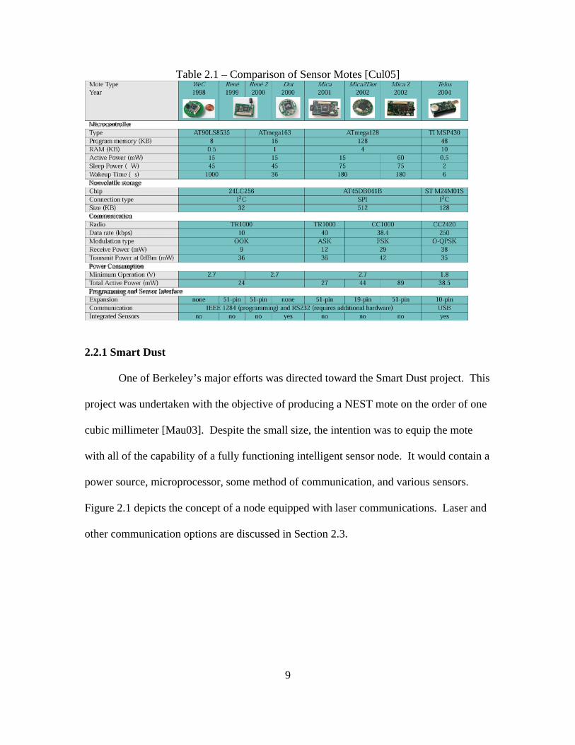
Table 2.1 – Comparison of Sensor Motes [Cul05]
2.2.1 Smart Dust
One of Berkeley’s major efforts was directed toward the Smart Dust project. This
project was undertaken with the objective of producing a NEST mote on the order of one
cubic millimeter [Mau03]. Despite the small size, the intention was to equip the mote
with all of the capability of a fully functioning intelligent sensor node. It would contain a
power source, microprocessor, some method of communication, and various sensors.
Figure 2.1 depicts the concept of a node equipped with laser communications. Laser and
other communication options are discussed in Section 2.3.
9
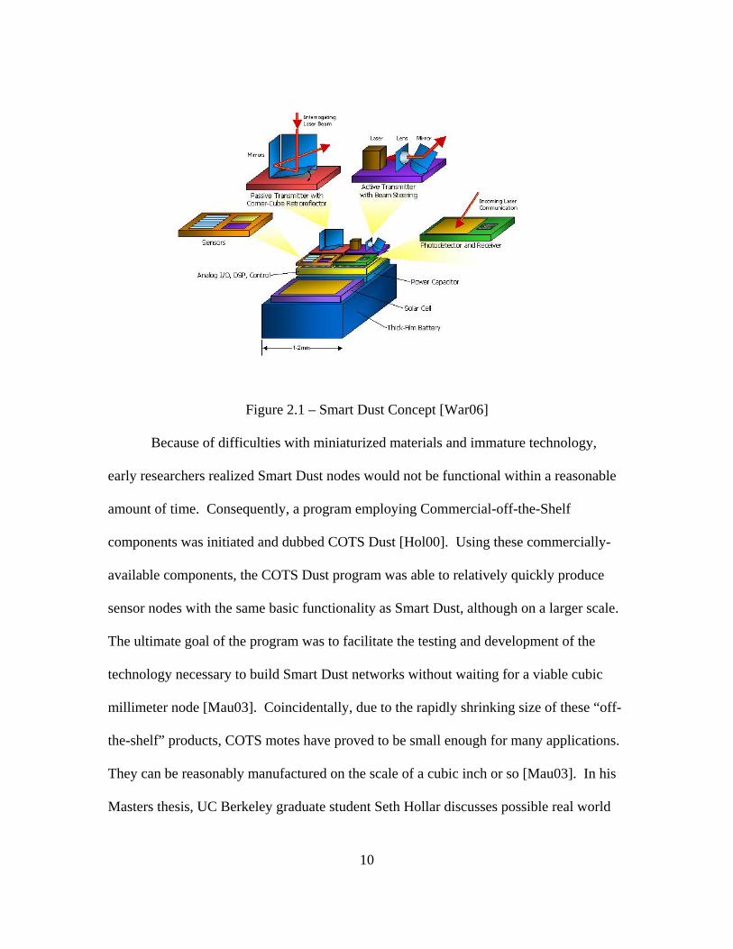
Figure 2.1 – Smart Dust Concept [War06]
Because of difficulties with miniaturized materials and immature technology,
early researchers realized Smart Dust nodes would not be functional within a reasonable
amount of time. Consequently, a program employing Commercial-off-the-Shelf
components was initiated and dubbed COTS Dust [Hol00]. Using these commercially-
available components, the COTS Dust program was able to relatively quickly produce
sensor nodes with the same basic functionality as Smart Dust, although on a larger scale.
The ultimate goal of the program was to facilitate the testing and development of the
technology necessary to build Smart Dust networks without waiting for a viable cubic
millimeter node [Mau03]. Coincidentally, due to the rapidly shrinking size of these “off-
the-shelf” products, COTS motes have proved to be small enough for many applications.
They can be reasonably manufactured on the scale of a cubic inch or so [Mau03]. In his
Masters thesis, UC Berkeley graduate student Seth Hollar discusses possible real world
10
applications [Hol00]. He uses environmental monitors or data loggers as examples since
extremely small nodes would not be required for those types of activities [Hol00]. A
similar line of logic could apply COTS devices to functions such as machinery operating
monitors, various types of perimeter control, or structural monitors on board aircraft
where it is not necessary for the devices to be inconspicuous.
2.2.2 weC Mote
One of the early devices in the cubic inch scale was called the weC Mote
[Mau03]. It was produced in 1999 and was one of the first devices to incorporate all the
basics of a fully functioning node. It was built with an eight bit Atmel AVR AT90S2313
microprocessor capable of 4 mega-instructions per second (MIPS) throughput at an
internal 4 MHz clock speed [Atm06]. This processor incorporated 128 bytes of flash
ROM for system programmability, and 256 bytes of internal memory. The device also
incorporated a RFM TR1000 RF transceiver, an integrated printed circuit board (PCB)
antenna, and temperature and light sensors [Mau03]. This structure gave the weC mote
some highly desirable characteristics for the early test and development effort while
occupying a space roughly the diameter of a silver dollar. First, the weC’s
communication capability and reprogrammable memory gave researchers the first device
that could accept new code via a wireless link [Mau03]. Second, the processor
capabilities facilitated the development of an operating system capable of handling
system requirements within the constraints of severely limited resources. Researchers
had realized early on that traditional software fell short when operating in such an
environment and developed TinyOS to address these shortcomings [LMG04]. While its
11
evolution continues today, TinyOS was initially employed simply as a communications
stack; it is discussed in more detail in Section 2.4.
2.2.3 Rene Motes
Following the weC, the Rene mote was produced by Crossbow Technologies.
The Rene and Rene 2 motes were very similar in design and components to the weC
motes, although they incorporated more memory and a modular design [Mau03]. The
sensor board and motherboard were connected together via a 51 pin connector. The basic
sensor board had temperature and light sensors, but could be expanded via a second 51
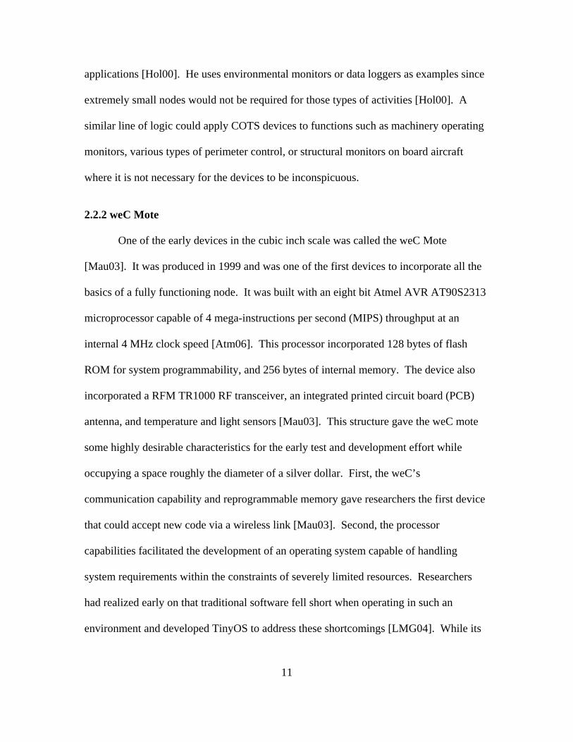
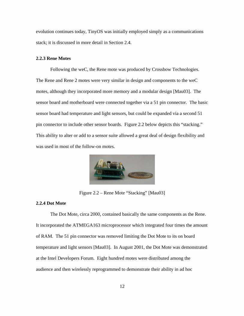
pin connector to include other sensor boards. Figure 2.2 below depicts this “stacking.”
This ability to alter or add to a sensor suite allowed a great deal of design flexibility and
was used in most of the follow-on motes.
Figure 2.2 – Rene Mote “Stacking” [Mau03]
2.2.4 Dot Mote
The Dot Mote, circa 2000, contained basically the same components as the Rene.
It incorporated the ATMEGA163 microprocessor which integrated four times the amount
of RAM. The 51 pin connector was removed limiting the Dot Mote to its on board
temperature and light sensors [Mau03]. In August 2001, the Dot Mote was demonstrated
at the Intel Developers Forum. Eight hundred motes were distributed among the
audience and then wirelessly reprogrammed to demonstrate their ability in ad hoc
12
network discovery, routing, and aggregation [Mau03]. The Dot Mote utilized an
improved version of TinyOS which included capabilities such as a concurrency
framework, messaging and networking stacks (radio frequency and serial), basic
multihop routing, network aggregation and querying, and mote simulation.
2.2.5 Mica Motes
In 2001-2002 the Mica Motes were produced to address some of the shortfalls of
the Rene and Dot Motes. While the microprocessor performance remained roughly the
same, there was a significant increase in storage capability. The Mica contained eight
times the amount of program memory and four times the data memory of the Rene 2
[Mau03]. This had a big impact since the code size of prior versions was severely
limited. The Mica also had four times the radio bandwidth of prior models, enhancing
the communication and networking capabilities.
Along with the Mica structural changes, TinyOS underwent some significant
changes. UC Berkeley developed a programming language specifically for TinyOS and
called it nesC (pronounced “NES see”) [Mau03]. This was a language based on the
popular C programming language. With the development of nesC, TinyOS 1.0.0 was
released in October 2002, along with a number of client applications.
The biggest development of the Mica series was the new radio communication
capability. The Chipcon 1000 radio chip gave the Mica the ability to communicate in the
400 MHz and 900 MHz bands as well as the capability of frequency modulation
[Mau03]. Furthermore, it was able to implement Manchester encoding and software
13

programmable frequency hopping. Consequently, it was able to realize better noise
immunity, increased range, and some degree of security.
2.2.6 Telos Mote
One of the latest developments is Crossbow’s Telos Rev B (TelosB), which is the
basis of the Trio platform. The design of the TelosB resulted in a more capable node well
suited for research. It incorporates a faster 8 MHz processor and is accessible via an
integrated USB port [Cro06]. Additionally, its communications suite is capable of 250
kbps in the 2.4 GHz band and is 802.15 compliant. It offers a variety of sensor options
and maintains an ultra low power consumption profile. Like its predecessors, the TelosB
operates with the open source operating system, TinyOS.
2.3 Typical Structure
While there are many types of motes in existence, most share a fundamental
structure. For simplicity, the basic common structure will be discussed and where
convenient, the Trio Mote will be used as an example. It integrates the unique
capabilities of three prior systems – the Telos Mote, the eXtreme Scale Mote (XSM), and
the Prometheus solar power system (discussed below). The capabilities of the Trio with
its open source software, sensor suite, and accessibility make it an excellent candidate for
the research environment. The Trio provides the foundation for the wireless sensor
network test bed at AFIT’s research lab.
2.3.1 Processor
The core of any sensor node is its microprocessor. The ideal microcontroller unit,
or MCU, has vast amounts of memory (a mix of reprogrammable ROM and RAM), fast
14

speed, a robust instruction set, a variety of interfaces for I/O, and low power
consumption. Despite the fact that such characteristics are often at odds with each other,
Crossbow’s TelosB provides a good blend for Trio applications.
2.3.2 Power Source
The proverbial “Achilles heel” of these devices is often the power source. This is
perhaps the scarcest yet most critical commodity on board the node. The choice of power
source will ultimately determine the life expectancy of the node and can have an impact
on the overall design shape and size. Obviously, the small size desired for these motes
(even palm-sized COTS motes) severely limits the capacity of an on board power source.
Furthermore, with planned networks of tens or even tens of thousands of nodes it will be
infeasible to routinely manually change batteries. While some networks may be able to
employ nodes wired to external power sources, maximum flexibility is attained with on
board power generation or recharge capability.
2.3.2.1 Power Management
A mote power source must have certain characteristics or capabilities to be
effective. Some mote networks may only need to operate for short time periods, perhaps
hours at a time, however many applications will likely require months or years of
operation. This is not to say that individual mote power sources must be capable of
operating the planned hardware on a 100% duty cycle, 24 hours a day, for years on end.
Rather, power management schemes will be used to reduce consumption and extend the
life of each power source. Nodes can be operated for short time periods spaced out over
pre-determined intervals. Individual processors can be shut down or put in a “sleep”
15

mode, powering up on a set schedule to check for anomalies or network communication.
In very dense networks this power management schedule can be designed such that
enough sensors will be operating at any given time or location while allowing all sensors
to conserve energy. Proper consideration to this schedule will ensure that the aggregate
picture will not suffer from “black-out” periods or physical areas.
2.3.2.2 Power Density
Assuming an effective power management scheme, the next critical characteristic
is size versus energy supplied. Typical mote microprocessors operate at 3 volts and
consume currents on the order of tens of milliamps when active and microamps when in
sleep mode. The Telos (on board the Trio mote) for example consumes 20 mA and 5μA
in active and sleep modes respectively [JPC06]. Lithium batteries are generally well
suited to provide this power while conserving space since they offer the highest density
of commercially-available batteries (285 mWatt-hr/gram) [Hol00]. Other batteries can
offer a higher maximum current, however with space at a premium the 3 volt lithium
battery is a great compromise, and is in fact the power source Seth Hollar used in his
development of COTS Dust [Hol00].
2.3.2.3 Renewable Power
Despite an effective power management scheme and a high capacity, miniature
power source, remote nodes will have a finite life dependent upon initial battery capacity,
recharge capability, and duty cycle. Renewable power can reduce dependence upon
perishable sources and extend node life, however it normally comes with an increased
footprint and complexity. Renewable power supplies have seen widespread use for many
years, however incorporating them into the extremely low power setting and the
16

environments expected for wireless sensor nodes offers unique challenges. Professors
Jiang, Polastre, and Culler of UC-Berkeley say the ideal power system should be “simple,
robust, and operate with no human intervention for many years” [JPC06]. With this
vision, they designed the Prometheus solar charging system (Figure 2.3). The
Prometheus is the system used on the Trio and is presented here as a discussion of solar
power usage on motes.
Figure 2.3 – Prometheus with Telos [JPC05]
The goal of the Prometheus design was to overcome some of the typical
shortfalls of photo-voltaic systems while preserving a simple architecture [JPC06]. Some
systems use only capacitors as energy storage buffers, while in others the solar cell
directly charges the battery. In the former case, stored energy is rapidly depleted when
the light source is absent. In the latter system, the batteries are subject to multiple
recharge cycles whenever solar energy is available. Subjecting the batteries to frequent
recharge cycles will limit its life to less than approximately two years, which is little
different from batteries alone [JPC06].
Berkeley’s answer to this problem was an intelligent charging control mechanism
based on solar energy [JPC06]. Since capacitors can handle nearly unlimited charging
cycles, they were chosen as the primary energy buffer. Under normal conditions, which
17
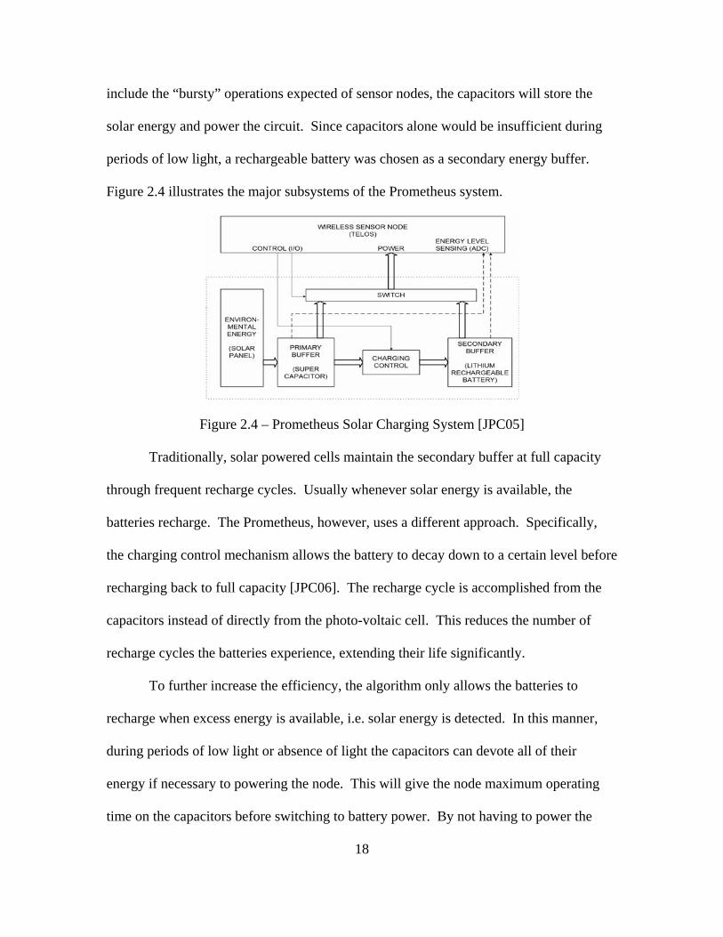
include the “bursty” operations expected of sensor nodes, the capacitors will store the
solar energy and power the circuit. Since capacitors alone would be insufficient during
periods of low light, a rechargeable battery was chosen as a secondary energy buffer.
Figure 2.4 illustrates the major subsystems of the Prometheus system.
Figure 2.4 – Prometheus Solar Charging System [JPC05]
Traditionally, solar powered cells maintain the secondary buffer at full capacity
through frequent recharge cycles. Usually whenever solar energy is available, the
batteries recharge. The Prometheus, however, uses a different approach. Specifically,
the charging control mechanism allows the battery to decay down to a certain level before
recharging back to full capacity [JPC06]. The recharge cycle is accomplished from the
capacitors instead of directly from the photo-voltaic cell. This reduces the number of
recharge cycles the batteries experience, extending their life significantly.
To further increase the efficiency, the algorithm only allows the batteries to
recharge when excess energy is available, i.e. solar energy is detected. In this manner,
during periods of low light or absence of light the capacitors can devote all of their
energy if necessary to powering the node. This will give the node maximum operating
time on the capacitors before switching to battery power. By not having to power the
18
node while simultaneously recharging the batteries, the capacitors may retain enough
energy to operate until solar energy returns. By minimizing the times the circuit must
switch to battery power (either by sleep schedules or by efficient capacitor usage), the
batteries may only see sporadic usage. If so, they will deplete mainly due to normal
leakage and consequently will undergo a minimum number of recharge cycles.
To take full advantage of this power control algorithm requires the ability to
modify energy consumption rates. Modeling the node’s energy usage as a function of
voltage supplied and current drawn, the sensor node can control its power consumption
by adjusting its duty cycle. Furthermore, since each node’s duty cycle can affect the
aggregate functioning of the network this information must be shared among the nodes so
that routing decisions can be made efficiently. For example, the network must ensure a
minimum number of nodes are active in any particular geographic region to prevent
sensor “blackouts” or communication stoppages. As a node returns to an active state
from a sleep state, another node may shut down to conserve energy. The controls for
active and sleep states will be dependent upon the density and health of the network as
well as mission needs, such as the required frequency of samples or maximum latency
tolerances. A very dense network may be able to allow longer sleep cycles. Conversely,
an application which can tolerant little sampling error may require shorter or less frequent
sleep cycles.
Jiang, et al, published estimated life expectancies of nodes utilizing Prometheus
based on various duty cycles. They estimate with a 1% duty cycle and 5 hours of light
per month, the Prometheus can power a node for 43 years. With a 10% duty cycle and 5
hours of light every 4 days, life expectancy was 4 years. They consider 1% or less duty
19

cycles in wireless sensor networks reasonable. Power management methods will affect
those numbers, as will the number and type of devices drawing power. In a dense enough
network, it may be possible to operate individual nodes at a 1% or less duty cycle,
altering wake states among the nodes, and thus effectively attaining perpetual operation.
2.3.2.4 Alternate Power Sources
In cases where extremely small size is desired, photovoltaic cells may not be
feasible. Consequently, there is much research currently being conducted into alternate
power sources. The overall goal of such sources is to supplement on board, perishable
power supplies or even to supplant them entirely. An overview of some methods tiny
devices can utilize to scavenge power, as well as estimates of their potential yield is
found in [Ste04]. The methods include temperature gradients, human power, vibrations,
and air flow. While none of those sources can currently replace traditional power
supplies, they show great promise and can certainly extend the life of the node.
The scavenge method which may have the highest yield exploits waste heat or
ambient temperature from the surrounding environment. Assuming a 10o C temperature
gradient, it is theoretically possible to generate approximately 1 mW/mm2 [Ste04].
Exploiting the human body for this method can generate up to a 15o C temperature
gradient. Another method involving human power uses motion. The act of stepping can
generate 330 µW/cm2 from the energy absorbed by the shoe.
Similarly, energy may be generated from vibrations. Vibrations are abundant in
most environments where humans operate or hold interest. They are caused by many
phenomena, including normal machinery such as environmental control systems and
20
engines. Energy which can be derived from vibrations similar to those generated by a
clothes dryer is approximately 800 µW/cm3 [Ste04].
Environmental weather may also have properties which can be exploited. Air
flow, for example, can be used to generate approximately 1 mW/cm2, although that is
assuming 100% efficiency. Other options may include exploiting pressure gradients,
micro-fuel cells, or radioactive power [Ste04].
2.3.3 Sensor Suite
The type of sensors available give the wireless sensor network designer a great
deal of flexibility, although they vary significantly in effective distance and power
consumed. Most motes have the capability of expanding their sensor library via external
connectors. The Trio does not have external connection capability, but contains a sensor
board equipped with passive IR (PIR), magnetic, and acoustic sensors. Typical sensors
consume on the order of hundreds of microamps [Hol00]. For example, light sensors
consume approximately 200 μA while magnetometers consume 650 μA.
Depending on the application, different types of sensors will have to be integrated
either on the same mote or on different motes operating together. For example, to
discriminate between civilians, soldiers, and vehicles in a perimeter zone, one solution
could combine PIR, magnetic, and acoustic sensors. The three sensors could differentiate
between various characteristics. The heat and acoustic signatures of the civilian and
soldier would be similar to each other, but significantly different from that of the vehicle.
The magnetic content of all three should differ, assuming an armed soldier but unarmed
civilian. In this example, a detected event which matches the IR and acoustic pattern of a
21

human being could be identified as a soldier if a certain threshold of metallic content was
also measured.
In contrast, nodes designed for highly specialized purposes may be able to operate
autonomously. For example machinery operating monitors or structural monitors might
only require one particular sensor. Sensors for anomalies such as acceleration, proximity,
vibration, or perhaps GPS (node location) may provide the required information
individually.
2.3.4 Communications
The functionality of the sensor node is limited without the ability to communicate
with the network around it. There are multiple ways to accomplish this task wirelessly.
Many motes are designed to communicate via radio frequency (RF) and use the 802.11
protocol. Two other possibilities are acoustic and optical. In any case, power consumed
and size of communication devices can drive the designer’s choice.
2.3.4.1 Acoustic Communications
Acoustic systems use transducers to transmit data encoded as sound waves.
These systems can consume very little power, however they are especially subject to
background noise and signal attenuation [Hol00]. Furthermore, the size of the transducer
severely limits the output power attainable, making them even less effective as the node
decreases in size. There may be some utility to acoustic systems transmitting certain
signals, such as locator beacons, but in general they are not as prolific as other data
transfer systems.
22

2.3.4.2 Optical Communications
Optical systems generate a laser beam to encode the signal and can be categorized
as active or passive [Hol00]. Passive versions do not generate their own laser on board,
instead they use a system of micro-electromechanical systems corner-cube-reflectors
(MEMS CCR) to reflect or scatter the laser from the source. The data is encoded by
modulating the light which gets reflected back to the source. Using this scheme, the
power consumed is considerably less than if the node had to generate a laser beam itself.
The cost of moving the CCRs is approximately 100 pJ/bit [Hol00]. This method requires
an external device to generate the beam and then receive and decode the signal. The
beam generator must also be able to find the device and direct the energy accordingly.
Furthermore, the mote must have its reflective surfaces positioned such that they can
receive the laser energy and have the mobility necessary to deflect it away from or reflect
it back to the source.
Active optical devices incorporate the laser beam generator on board. A message
is transmitted by first directing the laser at the desired receiver, then modulating the beam
to encode the data. The advantage of such a communication system is its long range and
precise beam. Laser communication was demonstrated between COTS Dust devices over
20 km apart [Hol00]. The laser beam is not transmitted in all directions, instead it is
focused very tightly with a small divergence. The divergence of the beam can be
calculated with respect to the wavelength as
θDIV = 4λ / πa, (1)
where a is the aperture diameter in meters and λ is the wavelength in meters. The typical
optical wavelength is on the order of 700-350 nanometers [Hol00]. Assuming an
23

aperture diameter of 1 mm (SMART Dust sized) yields a divergence of less than 1 milli-
radian. The divergence at 20 kilometers is less than 18 meters.
While the precision of the beam can help to ensure no unwanted nodes are
receiving it, the small area covered by it raises this method’s biggest problem. That is the
fact that the laser transmitter must precisely locate the receiver and then steer the beam
appropriately. Even in the case where both the receiver and transmitter locations and
orientations are known with a high degree of accuracy, the search pattern and steering
mechanism complicates both the hardware and the software of the node. In the case
where the locations are not known, this may prove to be a prohibitive limiting factor.
2.3.4.3 RF Communications
Most motes use RF communication, although that presents problems for smaller
devices, especially SMART Dust-sized devices. RF communication is well established
and has many commercially-available components. Typical RF transmitters can operate
in the 30 to 40 milliwatt range, although such power levels result in transmit distances of
less than approximately 10 meters [RAK02]. Boosting the power in order to
communicate farther than 10 meters results in a rapid increase in power consumed. Even
when the radio is in a listen mode, power consumption is not negligible when considered
over prolonged periods of time. Consequently, the node must closely control the duty
cycle of the radio, turning it off whenever possible. Typical devices schedule the receiver
to listen for certain periods of time and trigger the transmitter based on specific events.
For example, a node may be programmed to wake up and listen for network
transmissions 30 seconds every three minutes. It would transmit when it detects a
24

reportable anomaly or if it needed to relay a message from another node. All other times
it is put into an inactive state, drawing neglible power.
One other problem associated with RF communication arises from the antenna.
In contrast to the laser transmitter, RF energy is typically transmitted isotropically,
resulting in two adverse effects. First, the energy density is not nearly as great as that of
a focused beam. The power density of RF energy transmitted isotropically is
Ψi = Power / 4πr2, (2)
where Power is in watts and r is the range from the transmitter in meters [Rod01]. In
contrast, the power density of a laser is
Ψ = Power / Ωr2, (3)
where Ω is the surface area (meters) of the laser beam projected upon a unit sphere
[Wei06]. Examining these equations with our previous example of a beam with a 1
milliradian divergence shows a tremendous difference in power received at distance r,
decisively in favor of the optical signal. While both densities are inversely proportional
to range squared, the surface area of a beam with such a small divergence projected on a
unit sphere is extremely small. This factor alone yields a laser power density many times
greater than the isotropic transmitter.
The second effect of the isotropic transmitter is the non-discrimination of the
signal. This signal can be received by anyone within range, intended or unintended.
While that may be desirable from a routing perspective, it also raises some security
concerns as well as power management concerns. While a directed beam does not
guarantee security, it does help. If the beam is not focused, then other security measures
must compensate. Furthermore, the power drain of the isotropic transmitter has an effect
25

on both the transmitting nodes and the potential receiving nodes. Transmitters expend
energy in all directions, whether or not receivers are present. A focused beam (RF or
optical) could reduce the energy required to reach a particular receiver although this
introduces other problems as discussed in the Section 2.3.4.2.
Receiver nodes which are in range of the isotropically transmitted signal must
either unconditionally ignore signals (based on some set schedule) or expend energy to
listen to the signal and decide whether or not it was intended for them. This can be
accomplished through power management schemes or smart receivers, but regardless it
has an effect and must be taken into consideration.
As with any engineering comparison, this one is not without trade off decisions.
Laser beam generators and receivers can significantly increase the range attainable, but
will add complexity and power consumption to the circuit. For dense networks it may
not be necessary to transmit over long distances for most of the nodes, assuming multi-
hop routing protocols are implemented. This could allow the smaller, less complex RF
systems to be utilized. Furthermore, the environment in which the network resides must
be considered. Noisy RF environments may make it difficult for receivers to discriminate
signal from noise. Such a situation will likely result in corrupted packets and a
corresponding increase in power consumption. In that case, optical or acoustic
communication may need to be considered. Conversely poor lighting conditions or
obstructions present can limit the effectiveness of optical systems. Ultimately, the ideal
communication scheme may involve a combination of systems.
26
2.3.5 Network Topography
One of the properties that distinguish sensor networks from traditional networks is
their peer to peer ad hoc structure. Theoretically, networks of thousands of sensors could
be easily deployed over virtually any environment and able to set up a wireless ad hoc
mesh network. Each node would have the protocol necessary to communicate with its
neighbors and route data appropriately while controlling its power consumption to ensure
a useful lifetime. While individual nodes are not equipped with tremendous computing
power or vast quantities of memory, the aggregate function of the network ensures
information collected gets processed and routed to the appropriate entity (a user’s PDA or
laptop for example).
This general structure gives the wireless sensor network three advantages.
Specifically, the network (1) has no reliance on a backbone infrastructure; (2) is scalable
to suit many types of applications; and (3) can be energy efficient [HoS05]. All three
properties are interrelated. These advantages can best be illustrated with an example.
Suppose a single sensor residing in a dense network of sensors detects an anomaly. The
single node may not be able to determine reliably the exact location or even type of
object causing the anomaly, but the event triggers its processor to send a message to the
user. Since its low power transmitter cannot reach the user, it must rely upon the built in
multi-hop routing protocol. It broadcasts a short message describing the anomaly to all
nearby nodes. Many of the nearby nodes are in sleep mode conserving power, but the
network scheduling protocol ensures enough of them are active to receive the message.
In this manner the message is relayed node to node, possibly getting routed to a higher
power transmitter, sometimes called tier 2, until it reaches the user interface. Any
27

processing required may occur between the nodes, required back and forth peer-to-peer
communication, or may occur at the user’s processor. Theoretically, such a network can
be scaled as big or small as necessary, although as size increases, so does the routing and
network management complexity.
Some networks may incorporate the tier 2 or gateway transmitters interspersed
throughout the network in order to reach more distant networks or allow the user to
occupy a more distant location. In this example, similar messages describing the same
event or related events (such as sound emanating from the object in motion) detected by
other sensors could be analyzed by the aggregate network and presented to the user
accordingly. There is no backbone in this example. The relay requires more complexity
within each node, but eliminates many infrastructure setup requirements, such as routers,
hubs, switches, etc. It also increases the overall energy efficiency. In order for one node
to transmit a signal all the way to a distant hub, the power increase would be prohibitive.
As mentioned previously, power required is inversely proportional to the square of the
distance. By utilizing multiple hops, each transmitter only has to expend enough energy
to transmit a short distance. Thus the resulting power required is proportional to the
number of nodes between the source and the destination [HoS05].
2.4 Operating System
Throughout the discussion so far, many capabilities or characteristics were
presented with little consideration for the operating system. With such a small platform,
limited memory available, perishable power supplies, and often unique hardware, the
operating system is no small issue. The accepted standard for sensor nodes has become
28

TinyOS, designed by the EECS Department at UC Berkeley. Traditional operating
systems do not have to contend with the severely limited resources typical of a micro
sensor node, and so are generally not suited for these applications. To fit the unique
requirements of wireless sensor networks, the functionality of TinyOS was designed to
satisfy three broad requirements [LMG04]:
• Take account of current and likely future designs for sensor networks and sensor network nodes.
• Allow diverse implementations of both operating system services and applications, in varying mixes of hardware (in different mote generations) and software.
• Address the specific and unusual challenges of sensor networks: limited resources, concurrency-intensive operation, a need for robustness, and application-specific requirements. As a result, TinyOS is a modular, event-driven operating system which facilitates
flexible design and power management [LMG04]. The modularity of the system allows
it to handle different or perhaps new hardware interfaces, while maintaining certain basic
applications or services, such as networking functions or timers.
TinyOS’s concurrency requirement stems from one of the basic differences
between traditional computing systems and nodes. These nodes have extremely scarce
storage capacity and limited ability to perform computations. Consequently, they must
“process multiple information flows on the fly,” executing sometimes several operations
simultaneously [LMG04].
The event driven property allows a node to execute functions efficiently while
conserving its limited power. While inactive, TinyOS enters an ultra low power, sleep
mode. Actions are triggered by hardware “events” such as sensor activations,
communication reception, or perhaps internal timers. These “events” are passed to the
29
operating system via interfaces, which generate interrupts. Interrupts, in turn, result in
tasks, or procedure calls, which the node must run. These tasks are either executed or
queued for later execution. TinyOS maintains its very low power profile until a task
enters the queue. The operating system works to exhaust the queue, then it re-enters
sleep mode.
In this manner, TinyOS provides developers a unique level of control over the
hardware of these nodes. It allows the compilation of only the code required for specific
applications within a particular node and reduces some of the traditional layering of the
OSI model [HoS05]. TinyOS is able to control the complete range of layers itself, and
developers can directly modify any layer as necessary to perform a particular function.
This type of close control maximizes use of scarce memory and power resources. Recent
kernel modifications to Linux give it significant capabilities in this area as well, although
TinyOS appears to remain the operating system of choice [HoS05].
Levis, et al, present three examples to illustrate the requirements different
applications impose upon the operating system, and the functionality that has been
developed to handle those requirements. The first is a habitat monitor. In this case, data
are required over prolonged periods of time from certain environments. Queries for
specific types of data are distributed to the sensor nodes via RF communication. The
nodes must understand the query and gather the appropriate data. TinyDB was developed
as a database handler to collect data in this manner. This application needs to keep power
consumption to a minimum in order to allow sensor operation over a prolonged period of
time. In this case, the nodes can “sleep” until activated by a query. When queried, the
30
node takes its reading, transmits the data, and returns to sleep. The event-driven model of
TinyOS facilitates such an operation.
The next example is a shooter localization. In this case, the sensor network must
determine the location of a sniper based on the nodes’ ability to detect the bullet. Certain
sensors can detect the shockwave of the bullet traveling through the air, as well as the
sound of the shot. It is reasonable to achieve shockwave detection latency on the order of
tens of microseconds [LMG04]. Nodes can estimate the distance based on timing
between the shockwave and the sound of the shot. This information is communicated to
a central controller where the actual location is computed. This example places different
constraints upon the operating system. It requires a relatively high sample rate and close
time synchronization, at least during the period of the shooting. The application must not
only detect the anomalies, but also synchronize itself within the network and perform
computations on the data gathered.
As a final example of a unique requirement, a pursuer-evader situation is
presented. This involves a network of sensors tracking the movement of one entity and
feeding the information to another entity in pursuit. Fusion of data from multiple,
changing sensors must occur and accurate location must be computed. Obviously, this
requires precise knowledge of mote location and a dynamic type of routing. Information
is first routed to the central controller, but then must be routed to the mobile entity in
pursuit, which could be anywhere in the network. Latency could be a factor as well,
depending on relative speeds of the entities. This example illustrates the concurrency
requirement. Sensors may need to simultaneously process data or respond to queries
while forwarding packets from other nodes.
31
All three situations present unique and demanding situations to tiny, resource-
limited devices. Just as the applications which can employ these services are endless, so
too are the solutions. TinyOS and the myriad functions which have been, or are being
developed for it set the stage for a new frontier of information gathering. As hardware
gets smaller, faster, more sensitive, and more powerful, the application base will expand,
limited only by the imagination of the designer.
32
III. Analysis and Results
3.1 Chapter Overview
Multiple types of applications are examined in detail to determine the relevance or
utility of a wireless sensor network. The applications are examined with respect to their
expected operational environment and their methods of information gathering and
dissemination. The following discussion presents those applications which could benefit
from a WSN with an emphasis on the particular aspects of the technology which must be
developed or tailored to satisfy specific requirements. In order to present a complete
picture, general categories of applications and deployment methods are first discussed
since there are significantly different requirements for each. Subsequently, individual
specific applications are presented. Most of the applications involve some type of
perimeter monitoring, although there are several specialized uses as well. Estimations of
effectiveness are made, although this analysis is strictly speculative, i.e., no field testing
was specifically conducted. Overall, the applications listed here were selected because
they can benefit from a smartly implemented WSN.
3.2 Categories of Applications
Most applications can be broadly categorized as static or dynamic. Static
applications are in pre-determined environments where mote locations are known and
any necessary infrastructure may be constructed. That infrastructure includes housing for
the sensors, fixed antennas, powerful relay stations interspersed throughout the field, or
even fixed power and/or communication links. The location may be considered long
33

term, if not permanent. An example is home base airfield perimeter monitoring or
machinery operating monitors.
Dynamic applications have varying degrees of pre-planning, but generally are not
permanent and have little, if any, available backbone infrastructure. Dynamic
applications can be either reactive or preemptive. Reactive is a network set up in
response to some time critical trigger. An example is a network set up to determine the
strength of a newly discovered enemy troop formation. Preemptive dynamic networks
are similar, although the user would have the time to set up a network in an expected area
of interest. For example, current intelligence indicates a likely avenue of approach for
enemy troops in the near future. Friendly forces could establish the network to monitor
the area and give early warning of the enemy’s advance.
Finally, there is a distinction between methods of constructing the network.
These can be categorized as emplaced versus scattered. When possible, precisely
emplaced motes are desirable for a few reasons. The network can be planned in great
detail, ensuring adequate coverage of sensors while simultaneously ensuring all motes are
able to communicate with the network. Additionally, the location and orientation of each
node can be controlled, and such information would be available to the node itself and to
the central controller. Emplaced nodes are the preferred alternative for static networks,
but could possibly be implemented in dynamic networks as well depending on time
available and accessibility to the environment of interest.
Scattered nodes offer the greatest degree of flexibility, although they present
problems as well. The method used to “scatter” them depends on several factors. The
structure of the mote, type of sensor, type of communication, robustness of housing, type
34

of environment, network density required, and even weather conditions affect the
scattering method. The simplest concept is to “toss” them into the area of interest.
Tossing may be done manually or by some delivery mechanism, for example airborne
delivery, propelled canister, etc. Very small sensors could be dispensed from an airplane
in a similar fashion that crop dusters dispense pesticide.
Another alternative could be delivery via a device similar to a cluster bomb unit
(CBU). The CBU is a canister which is dropped from an aircraft and is pre-programmed
to open at a certain altitude scattering its contents over the desired area. A similar type of
canister could be delivered by ground based systems such as artillery, mortars, grenade
launchers, or even sling shots. Smaller delivery devices will result in smaller canisters,
and ultimately a smaller nodal footprint.
Some types of sensors may require additional mechanisms to ensure proper
alignment with a particular axis, while others may have specific antenna requirements.
Furthermore, scattering introduces several factors which will be hard to control but will
have an effect on the network, such as density, distance between nodes, built-in
redundancy, impact with the ground, etc. Dynamic networks with scattered nodes
introduce a seemingly infinite number of variables, many of which are application
specific and must be addressed as such.
3.3 Applications
3.3.1 Static Perimeter Monitoring
A wireless sensor network can provide a valuable tool in the area of perimeter
security. Perimeter surveillance based solely on the human eye can be inadequate. Even
35

modern methods of electronic surveillance can be cumbersome, costly, or limited in
scope. A network of sensors can realize several key advantages over traditional systems.
First, the sensor network coverage can be molded to fit whatever breadth or depth
is required. Nodes can be placed as needed to ensure the proper density and sensor
coverage, emphasizing critical points or key avenues. These nodes can be installed in
virtually any environment and can even be concealed if necessary. Concealment and
randomness of placement will make defeating the network a more difficult task. The
network can incorporate multiple types of sensors to build a complete picture of the
perimeter. Additionally, redundancy can be built in to the network giving it fault
tolerance.
A prime example of particular interest to the U.S. Air Force is flight line and air
base perimeter security. There are two scenarios for base security which bring to light
different requirements. The first is a CONUS air base which does not have the
anticipated threat of attack by unit sized forces and may not have a large buffer zone
between it and the outside world. In this case, the sensors can be placed in or on the
fence structures which typically enclose bases. Since the area immediately on either side
of the fence is normally protected as well, sensors would have to be placed close enough
to each other so that their detection zones would overlap out to the appropriate distance.
Additionally, a variety of sensors would have to be used to be able to discriminate
extraneous motion (i.e., animals, wind, etc.) from actual threats. For example, IR and
motion detectors could be combined with appropriate algorithms to eliminate false alarms
from animals and swaying plants.
36
Furthermore, the network should be smart enough to report not only an entity on
one side of the fence, but also report the motion of the entity across or through the fence
line and ultimately which direction it departed the sensors’ field of view. Comparing the
information from two or more nodes in the vicinity of the event can reveal the penetration
point and numbers of intruders. A central computer can compute direction of motion
based on differences of signal strength between nodes at various time intervals.
Finally, the latency of such detections must be relatively small. Since the
perimeter is a thin line, by the time detection is reported, the perpetrator could already be
through the fence. Once security forces are dispatched, the network would have to route
any new information to mobile users, i.e., to patrol cars or forces on foot equipped with
PDAs.
Taking this concept to an extreme, an entire base could be equipped with sensor
nodes throughout its interior. If so, security forces could track a suspect (or anyone for
that matter) anywhere on the base provided the network had two very important
capabilities. First, the sensors must be able to maintain continuous track on the target.
This would avoid ambiguities with collateral tracks as the intended target moves between
sensor fields. Adjacent nodes would have to implement positive hand-off of track files
from node to node. Second, the network would have to be able to pinpoint the target
within a certain tolerance. If nodes can only determine whether or not a target is within a
maximum radius from it, but not a bearing and range, then it would be necessary to
triangulate between multiple nodes and publish an ambiguity zone. This zone would
indicate to security forces that the target was within a confined area rather than
pinpointing a single target.
37
The concepts of the CONUS air base apply to a deployed air base as well with a
few key distinctions. The worst case deployed air base is one in or near a hostile area
with a threat of attack by unit sized military forces. Prince Sultan Air Base is a good
example. The wireless sensor network would be similar to the CONUS “fence” example,
except that the depth of the network could expand to fill whatever buffer zone the base
can utilize. Individual nodes can be camouflaged in the existing environment and should
be placed densely to avoid localized “blackouts”. Furthermore, random placement of
nodes will reduce the ease with which a malicious agent can discover and target
individual motes.
With this type of WSN, security forces could have access to additional important
information. They would get an earlier indication of intruders (out to the edge of the
buffer zone, potentially miles from the perimeter of the base), and they could track the
intruder(s) through the buffer zone. Additionally, in the case of an active assault on the
perimeter, the network could give assistance with shooter location and numbers. This
concept will be explored more in depth in Section 3.3.3.5.
To complete the picture, the base could employ specialized sensors at certain key
locations, such as gates or near buildings close to the perimeter. These sensors would
detect anomalies such as nuclear, biological, or chemical (NBC) agents. Again, latency
is important although it is more so in this case. Real time warning of NBC substances
could give security forces sufficient time to prevent their entry to the base or perhaps
facilitate the evacuation of the affected area in time to avoid casualties. The Khobar
Towers incident provides a great example of a situation where an effective wireless
sensor network with the appropriate sensors could have helped to avert or deflect an
38

attack. Secretary of Defense Cohen referenced a Defense Special Weapons Agency
study which reported that the truck carrying the weapon was full of approximately 20,000
pounds of explosives [Coh97]. A smart network could detect the explosive material and
alert occupants of the nearest buildings (via closed circuit TV, base LAN, and/or the
Giant Voice system) while simultaneously sending the information to the security forces.
It would also note the numbers and types of vehicles and personnel involved and their
departure direction.
Despite the potential capabilities, there are a number of problems raised by a truly
integrated perimeter monitoring system of this scale. Specifically, the most significant of
problems include:
1. Deployment of nodes 2. Maintenance or upkeep of the network 3. Routing 4. Compilation or fusing of information gathered 5. Network longevity 6. Handling legitimate personnel and equipment movement in and around the
network The first four problems are interrelated and are due to the sheer numbers of nodes
necessary to provide seamless coverage around a base. The following example illustrates
the scope of the problem. Assume a network is placed around the perimeter of a base
with a density of 1 node per 100 m2 (or roughly 1000 ft2). This equates to approximately
10 m (32.8 ft) between nodes. For simplicity, the base is a circle and the network either
occupies the fence surrounding the base or forms a ½ nautical mile (nm) band around the
base. Table 3.1 approximates the number of nodes required.
39

Table 3.1 - Perimeter Monitoring Zone Nodes Required
Node Coverage Base Diameter (nm) Approximate Nodes Required
Single line of nodes along circumference (fence) 3 1,900
Buffer zone ½ nm deep around base 3 88,000
Buffer zone ½ nm deep around base 5 140,000
Deployment of such a network would be labor intensive if it involved more than
scattering the nodes and routine maintenance or upkeep of the network could quickly
become untenable. It is simply not feasible to troubleshoot or adjust individual devices,
let alone change batteries, in a pool of hundreds of thousands of nodes. Human
intervention should be limited to the initial deployment, replenishment of nodes, and
monitoring of the results.
The number of nodes required could be reduced by increasing the distance
between nodes, especially if external power was available to enable increased
transmission distances. This, however, could come at the cost of reduced redundancy,
fault tolerance, and sensor sensitivity. A more likely solution is to scatter disposable
nodes over the intended area and program the network to be self-diagnostic and self-
healing. It should be able to determine which nodes are broken, dead, or simply
ineffective (blocked for example) and adjust its data reporting and fusion accordingly. It
should also be able to report to human administrators when a particular location requires
replenishment.
The problems of routing and information fusion are new twists to old paradigms
that are currently undergoing much scrutiny in the research and development
40
communities. Determining the appropriate multi-hop route to send data from a sensor
node to central computer is no simple task in these large scale, dynamic ad hoc networks.
Similarly, compiling and fusing the data from thousands of nodes into one coherent,
relevant, and timely picture is a challenge in its own right. Both of these problems must
be solved before wireless sensor networks can be used efficiently in large scale perimeter
security. The network must be able to get information into the hands of users in the field
in real time.
Node longevity of use presents uniquely annoying problems. Disposable nodes
should have relatively long lifetimes, i.e., on the order of years. They must withstand
weather phenomena such as rain, wind, ice, snow, extreme heat, extreme cold, and
sunlight. Furthermore, the physical setting in which the nodes will reside must be
considered. Buffer zones are normally kept clear of obstacles, which sometime means
mowing or otherwise clearing vegetation. This may require special deployment
considerations, such as burying or alternate vegetation control methods. Areas subject to
flooding or excessive snowfall may require elevation of the nodes. Replacing the
network after each mowing or each rainfall is simply not an option.
Finally, the problem associated with personnel movement in the vicinity of the
network may be the easiest to solve with existing technology. The algorithms must be
able to discriminate legitimate traffic nearby and through the network from reportable
traffic. In its simplest form, this could be done by human operators, entry control points,
and fixed schedules, although once again scale could present problems. Other solutions
could incorporate electronic identification such as radio-frequency ID tags or the
Identification Friend or Foe (IFF) system used on aircraft.
41

3.3.2 Dynamic Perimeter Monitoring
Any unit setting up a temporary base camp or operating area on potentially hostile
terrain must establish a perimeter. Similarly, units conducting sustained operations in or
near enemy territory must maintain vigilance. Wireless sensor networks could facilitate
monitoring that perimeter and provide life-saving, mission essential early warning of
enemy activity. Upon initial entry of friendly forces into a hostile zone, this degree of
monitoring is not currently available. Units often rely upon human sentries until more
formal structures can be erected. A real world example of such a deployment is our entry
into Bosnia in 1995. US Air Force units deployed with the Army to occupy areas of the
country with little or no infrastructure. Almost immediately they were tasked with setting
up control tower and airfield operations. A similar situation existed more recently in Iraq
and Afghanistan. This initial deployment and camp set up may be the most vulnerable
time and could benefit greatly from an easily configurable, adaptable, wireless
monitoring system.
The concepts previously discussed in the static perimeter monitoring section apply to
the dynamic scenario with a few key distinctions:
- Time is critical, both network set up time and duration of operation. This is perhaps the most significant difference.
- The unit may not control a buffer zone outside its perimeter. - The deploying unit normally cannot choose or change location. - The unit may not have the time or resources to modify the environment to
accommodate special node requirements, such as removing vegetation or other obstructions. This may drive the selection of network structure (density of nodes, type of sensors, communication methods, etc.)
- Reporting methods may be different. They may focus on reporting more raw data to an end user with limited computing resources available.
- There is often no infrastructure.
42
The critical nature of time has two important effects. First, the unit does not have the
luxury of extensive network planning or precise node emplacement. Second, the network
is not intended to operate indefinitely. Rather, it may be temporary until the unit departs
or it is an intermediate measure until a permanent network can be constructed.
Consequently, it does not have to last through years of adverse weather, vegetation
growth, or other detractors.
No matter how a unit first arrives at its temporary location in hostile terrain, it will
most likely be resource and time limited. The first problem is how to deploy the network
as quickly as possible. The nodes should be small enough that the unit can transport
them, along with their power supplies and supporting equipment, to the deployment
location. Additionally, they should be flexible in their emplacement. Specifically, they
should not require special care to ensure proper orientation, location, or height above the
ground.
In many cases it will not be feasible to walk or drive over the terrain to emplace
the nodes, due to threat of enemy action or minefields. In these cases, remote scattering
methods as discussed in Section 3.2 must be available. For most units, deploying a 360o
perimeter will require a robust method such as aircraft or artillery delivery. In other
cases, where a single avenue of approach must be monitored, sling shot or catapult
delivery may suffice. In any case, scattering could result in an imperfect or patchy
network. Similarly, the environment could have the same result. For example, rocky or
porous terrain may isolate some nodes or sections of nodes from the rest of the network.
Consequently, the network should be able to monitor its own health and report to the
43
users which locations require additional sensor coverage, allowing the users to “patch”
the network accordingly.
The method of determining network health depends on the situation. Some
applications will require a greater nodal density than others, and consequently those
applications can tolerate smaller outages. For example, a network designed to detect
mines cannot accept any gaps in sensor coverage while a network whose primary focus is
detecting approaching vehicles is more tolerant. The network as a whole must be
programmed to know the desired density in order to report its health. This could be
accomplished through the distributed processing capability of the nodes themselves or by
reporting individual node status to a central computer which can build an aggregate map
of the network.
The biggest problem which must be overcome with hastily or randomly emplaced
nodes is self localization. When an individual node comes to rest, it will have to discover
the network and make routing decisions, but more importantly it will have to be able to
report anomalies in such a fashion that the end user will know where the anomaly has
occurred. This localization can take many forms, but in the end it is absolutely critical
that the user be able to quickly and easily determine precise locations of events. The
location may be relative to the user or central computer location, or it may be absolute,
i.e., latitude/longitude or other coordinate system. Additionally, individual node location
may be computed on board by the node’s processor or off board by a central processor.
On board computing may be more flexible, but will also be more complex, more
expensive, and consume more power. Nodes may be equipped with GPS receivers or
possibly even inertial navigation systems (INS). For most dynamic perimeter monitoring
44
applications however, it will not be feasible to equip every node with its own GPS or
INS. One alternative is to include a master node for a given area which can determine its
own location and propagate the information to its children. Location estimation via
directional antennas or sound from the master node is also possible [MKY05].
Some examples of localization algorithms which can be implemented via
distributed processing within the network include Ad hoc Positioning System (APS)-
Euclidean [NiN01], Map Growing [LSS04], and Anchor Free Localization (AFL)
[PBD03]. APS-Euclidean and Map Growing are efficient algorithms which can be
modified to handle the network irregularity expected of typical CAF applications
[NiN01] [LSS04]. This irregularity is due to the environment and scattering methods;
nodes will likely not be deployed in regular shapes or distributions. APS-Euclidean
requires anchor nodes and communication with immediate neighbors, hence it is not well
suited for networks with low neighbor density [LaR03]. The Map Growing algorithm
starts with a node at the origin of a relative coordinate system and propagates relative
position to neighboring nodes until the entire network is mapped [LSS04]. AFL
algorithms rely on ranging techniques between the nodes to obtain relative positions
[PBD03]. If as few as three nodes know their absolute position, the network can
transform its positions in the relative coordinate system to the global [PBD03]. As
network size grows, Map Growing accuracy declines, however AFL accuracy is
unaffected [Jor06].
An off board alternative could include the central computer determining the
deployed nodes’ positions and either transmitting the location to the node or maintaining
a network map database. A central location computation has a few advantages. First and
45

most importantly, it allows simpler and smaller individual nodes. Second, the central
computer is not as resource constrained as the motes will be. It normally will have access
to higher power and larger antennas and can take full advantage of the GPS. Finally, the
orientation and field of view of the central computer can be controlled more so than
nodes deployed via the dynamic methods discussed above.
Conversely, the central computation presents some obstacles. The most
significant obstacle is determining the locations of potentially thousands of deployed
nodes. These nodes may be only several feet apart from each other, but thousands of feet
distant from the central location. A possible solution could involve optical
communication. As mentioned in Section 2.3, the divergence of a laser beam is
extremely small. The optical localizer system would involve the following steps:
1. The master node determines its own location via GPS. 2. The master node “polls” its surroundings with a laser interrogator. 3. The master node records the azimuth of replies from deployed nodes and can
determine range based on timing. 4. Individual node position is then either transmitted to the node or stored in the
central computer.
The laser interrogator would sweep across the perimeter until detecting a reply
from a node. Nodes would be equipped with CCRs as discussed in Section 2.3.4.2 which
would enable them to communicate yet keep power consumption to a minimum. The
interrogator would capture bearing information by knowing the position of the
transmitting antenna when it received a reply. Range information could be obtained via
timing to and from the node. Multiple nodes which are within the laser beam width
simultaneously (as well as within a certain range tolerance) could simply receive the
same position information, however this would inject some position error into the system.
46
If a higher degree of accuracy is required, the laser beam width would have to be adjusted
or the nodes would have to adjust their reported position based on their known proximity
to each other.
Nodes which are not within the laser interrogator’s field of view (but can still
enter the network via multi-hop RF communication) have a couple of options. First, they
could simply transmit their data into the network without position information. The
network could determine rough location based on the routing path and latency. In its
simplest form, the non-located node is “near” the first node in the routing sequence which
is located. If higher fidelity is required, the second option is to estimate its location based
on one of the algorithms previously mentioned.
Another solution to node localization is to operate a master node similar to ground
based aircraft navigational aids, e.g., the Tactical Air Navigation system (TACAN). This
system transmits a RF signal with bearing information 360 degrees around the station.
An aircraft receiving the signal can determine its range from the station based upon
propagation delay between aircraft and ground station. Implemented in a WSN, any node
receiving the signal can determine its location relative to the master node. The downside
to this solution would be the additional strain on the individual node. The node must not
only listen to and analyze the signal, but must also transmit to the master for range
calculation, compute the range, and transmit to the master the results of the location
analysis. Assuming the nodes are not moving, however, this computation would only
have to be performed once. In contrast, the laser interrogator solution simply required the
node to reflect back a short byte sequence, node ID for example, and let the master
controller handle the rest.
47

Either solution (interrogator or TACAN) could be accomplished from the ground
station or from an airborne device such as a UAV. One of the advantages of the UAV is
coverage. It is not affected by terrain as much as a ground based emitter and can
potentially “see” more nodes. No matter the solution, the algorithm must be able to
handle unlocated nodes which join the network. Additionally, the network must be able
to report its overall position quality capability so that the users may make informed
decisions. In the case of the TACAN-like system, errors in position quality can vary
widely due to the divergence of the RF signal as it propagates away from the transmitter.
Finally, computing resources available to the network may have an impact on its
capabilities. While many units will deploy with adequate computing power, the extreme
situation is a small unit in the field with only a PDA available. Ideally, the distributed
computing capability of the network should be able to accomplish most of the functions
(shooter location, track, velocity, heading, etc.) Then the users’ handheld device simply
acts as a repeater for the results.
In summation, there are a few unique requirements for critical to ensuring the
feasibility of wireless networks as dynamic perimeter monitoring systems:
- Ease and efficiency of node deployment - Ability to remotely deploy nodes - Efficient, real-time, and continuous health monitoring - Node location determination and position quality reporting
3.3.3 Dynamic Perimeter Monitoring Examples
The following are example situations where these dynamic systems could be utilized.
48

3.3.3.1 Vehicle Convoys
3.3.3.1.1 Scenario
Vehicle convoys are a common occurrence in many U.S. military areas of
responsibility around the world. They are conducted for various purposes such as
movement of personnel and supplies, reconnaissance, psychological operations, targeting,
and others. These convoys are armed and manned appropriately, however there are many
reasons that they must stop and it is at those times that they are most vulnerable.
Current defensive measures employ armed sentries in a perimeter around the
vehicles. In areas of limited visibility such as hilly terrain, fog, smoke, dust, darkness,
etc., human monitoring is less than adequate even when equipped with night vision
goggles. Similarly, during prolonged stoppages such as those for damaged vehicles or
breakdowns, human monitoring may be difficult to maintain. In both cases, a wireless
sensor network could provide a picture previously not available, and provide it on a
continuous, long term basis if necessary.
3.3.3.1.2 Deployment
The typical makeup of convoys will often preclude any deployment method more
robust than mobile catapults or grenade launchers. Consequently, it may not be feasible
to establish a seamless 360o perimeter, however partial coverage may be sufficient.
Users could supplement their sentries by deploying small scale networks in particularly
vulnerable zones or likely avenues of approach.
The most critical aspect of deployment in this case is time. This network must be
functional within seconds from convoy stoppage. Lengthy delays in deploying nodes
49
and/or network establishment would render this system useless. The network discovery
process and sensor operation would have to begin as soon as the individual node comes
to rest. Routing tables must be built quickly so that sensor readings could be transmitted
almost immediately. Perfect efficiency in the routing table structure is not required since
the expected lifetime of the network is relatively short. Expediency of operation is far
more important. Furthermore, users should be able to inform the network of its expected
lifetime. The typical length of a convoy’s delay may be short enough such that the
network could operate continuously at full duty cycle. If the delay was expected to be
too long, the network would have to know this information in order to revert to its power
management algorithm.
3.3.3.1.3 Sensors
Ideally, the network should contain a mix of motion, metallic, and IR sensors.
With this combination, the network could detect dismounted troops or vehicles and
reduce false alarms due to factors such as wind and animals. Furthermore, the users
should have the ability to key the system to search for specific, expected threats, e.g.,
armored vehicles.
3.3.3.1.4 Considerations
Knowing the exact location of each node once deployed would not be necessary
for simple early warning, however such information could be useful if external fire was
being directed onto the threat. Convoys often have US Air Force Tactical Air Control
Parties (TACP’s) embedded with them for precisely that purpose. The TACP
communicates with airborne assets to direct fires in support of troops on the ground and
pinpointing the target would be highly beneficial. In the absence of retaliatory fire,
50

simply knowing a threat originates from a general direction, i.e., knowing in which
direction the nodes were deployed may suffice.
3.3.3.2 Combat Control Teams
3.3.3.2.1 Scenario
USAF Combat Control Teams (CCT’s) have many functions to include setting up
landing or drop zones in or near enemy territory. The CCT’s often operate as small
teams, yet must secure large areas for the purpose of bringing in slow, vulnerable aircraft
to off-load troops or supplies. A wireless sensor network can facilitate continuous
surveillance of the area while the team maintains a covert position. Real time knowledge
of enemy activity would allow them to make appropriate decisions concerning their
mission, i.e., delay the aircraft’s approach or perhaps engage and neutralize the enemy.
This scenario at its extreme is a two to three person CCT on foot. The CCT is armed and
carries radio communication equipment, however they may be limited in mobility and the
amount of equipment they can carry.
3.3.3.2.2 Deployment and Sensors
Network deployment for the CCT situation is similar to the convoy situation
except that it is likely longer term. They can use the same deployment methods to scatter
the network and often would require expeditious operation. Sensor types are the same as
for convoys.
3.3.3.2.3 Considerations
CCT’s may conduct covert operations. Therefore, nodes must not be conspicuous
when deployed or they may give away the CCT’s intentions. Additionally, as mentioned
previously, the CCT may not have a great deal of excess cargo carrying ability. For this
51

reason, supporting hardware must be kept to a minimum. Burdening the user with excess
cables, batteries, antennas, or computers may render the system undesirable. Ideally, a
small amount of grenade-size canisters full of micro-nodes and a PDA-type interface
should complete the system. Finally, system components must be weather proof.
3.3.3.3 Minefield Detection
3.3.3.3.1 Scenario
Any movement through or initial deployment to an area in or near a hostile zone
is fraught with the threat of concealed explosive devices. Current techniques for clearing
areas can be dangerous and time consuming. Furthermore, mine clearing assets can be in
high demand during initial deployment of troops. A wireless sensor network which can
be deployed and monitored from a distance can search for and pinpoint certain types of
mines.
3.3.3.3.2 Deployment
Deployment of a minefield detection network must be from a distance. Since the
area of interest is most likely a large area which will be occupied by troops and/or
vehicles, a robust deployment method is necessary. Catapult or grenade launchers will
probably not be sufficient. Aircraft or artillery delivery will likely be required. The
density of network nodes over the entire area of interest is of prime concern. If scattered
nodes end up spaced too far apart, there will be gaps in the coverage. Consequently, not
only should the delivery method attempt to scatter the nodes with the proper density, but
the network must determine its own coverage once it has been deployed.
Evaluating the network coverage will depend on knowledge of two things. First,
each node must know exactly where it has landed within inches. This knowledge will not
52

only serve to build a nodal map, but it will also allow the network to pinpoint mine
location. Second, the network must know the range capability of the sensors. Each
sensor has a field of view for the particular anomaly it can detect. This field of view
must be plotted for each node to ensure it overlaps with adjacent nodes such that there is
no gap in coverage. Overlap must occur beneath the surface of the earth, down to a depth
determined by the users based on knowledge of the explosives.
Finally, the deployed network must report a position quality index and a density
figure. The position quality index is based on how close the nodes can get to a desired
GPS quality location, i.e., how many satellites are visible. The density calculation must
take this position quality into account. These numbers will allow the user to choose from
the following options: attempt to repair the network, inspect the sparse areas by other
means, or discard the network entirely.
3.3.3.3.3 Sensors
The sensors required to reliably detect buried mines are relatively sophisticated
and must be very sensitive. Each node must be able to detect several anomalies
simultaneously. Mines may be constructed of various amounts metal or plastic and may
contain different types of explosives. Some may emit RF energy or contain magnetic
devices.
3.3.3.3.4 Considerations
Individual node size is not a factor, however the housing must protect the sensors
from the method of delivery. This is especially critical if the nodes are dropped from an
aircraft. Timing of network discovery and mine detection is not a concern either.
53
3.3.3.4 TACP (Target Location)
3.3.3.4.1 Scenario
Tactical Air Control Parties are embedded with Army units down to the battalion
level and often operate with company sized units. One of their main functions is to
coordinate for and provide control to attack aircraft hitting targets in close proximity to
friendly forces. Despite many advances in technological aids such as laser pointers, night
vision goggles, GPS, etc., this often involves the Forward Air Controller (FAC) getting
“eyes on” the target, which may be shooting at them, and talking the pilot’s eyes onto it.
This process can be time consuming and is fraught with inefficiencies. The target may be
obscured by terrain or camouflaged. Furthermore, the FAC on the ground does not
necessarily have the complete picture. For example, a large rock formation may pinpoint
the target from the FAC’s point of view, however the airborne pilot may see a dozen
similar rock formations. The art of target “talk-ons” is not easy and takes much practice
to master.
3.3.3.4.2 Deployment and Sensors
Deployment methods and sensor types would be similar to the CCT. One
noteworthy difference is that the TACP is often assigned a specific Area of
Responsibility. In Bosnia, for example, TACP’s were assigned specific sectors along
with their Army counterparts. In such situations, they could set up networks beforehand
in areas of expected enemy activity or areas of particular vulnerability. In other
situations, they might need to set up the network spontaneously in response to current
intelligence or observed enemy actions. In either case, the method of deployment would
normally be localized and short range. The network should be able to continue operation
54
for months at a time, and it should report to the TACP when it requires repairs or
replenishment.
3.3.3.4.3 Considerations
A wireless sensor network can be an aid to the TACP with some specific
considerations. They sometimes operate on foot but often use vehicles. Consequently,
the ideal hardware baseline would be small, light, and weatherproof. Any external
batteries or cables required for network management should be compatible with existing
equipment such as radios and GPS.
The biggest difference between this application and those discussed previously is
the fact this is offensive in nature. Often, TACP’s may be attacking multiple targets in
relatively close proximity. The FAC has to manage available assets according to many
factors such as type of target, hardening or camouflage of the target, nearby threats, type
of ordnance available, aircraft fuel remaining, and many others. For the WSN network to
be an aid, the following characteristics are desirable:
- Near real time reporting of events (within seconds) - Accurate location (within tens of feet, ideally within a few feet) and position
quality reporting (critical because of the close proximity of friendly forces) - Ability to poll sensors for specific information, i.e., the source of RF energy or
signature of an AAA battery in the midst of vehicles, buildings, or other obstacles. Response time such a query should be within seconds.
- Ability to declutter the display. In some cases, despite multiple targets detected, the TACP may need to concentrate on the single highest threat, e.g., a surface to air missile battery.
- Ability to transmit the information to aircraft or higher headquarters. - Ability to switch to a different network. Specifically, when on the move,
networks deployed initially should not interfere with subsequent networks. The ability to transmit information to airborne aircraft or higher headquarters can
give the TACP more flexibility and increase efficiency, however it should be compatible
55
with existing systems. The Close Air Support request system uses a specific format, as
do attack aircraft targeting systems. Implemented smartly, the WSN could get target
information from an “on the spot” sensor directly to the tasked aircraft. The true strength
of the WSN lies in the capability to provide the FAC with accurate target location and, to
some extent, identify the target where beforehand such information was difficult or
dangerous to obtain.
3.3.3.5 TACP/CCT Firefight
3.3.3.5.1 Scenario
Both TACPs and CCTs operate on the ground in imminent contact with the
enemy. Often, the threat today consists of small units looking to strike fast, inflict
maximum damage, and escape quickly. Friendly troops reacting need to seek cover
initially, but must return fire to survive. Those two actions are often conflicting. In these
types of scenarios, a rapidly deployed, real time WSN can help accomplish both.
3.3.3.5.2 Deployment
Deployment methods are similar to the convoy example in that networks must be
easily and quickly deployable, and must be operational within seconds. Since this
network is reactive, delivery mechanisms should be simple; a sling shot, mortar, or
grenade launcher, perhaps.
3.3.3.5.3 Sensors
The sensor suite required for this application is also similar to the convoy
example (motion, metallic, and IR) with a few key distinctions. First, this network
should incorporate acoustic sensors. Second, network nodes must be able to self-locate
with a reasonable degree of accuracy (certainly within meters). To be useful in an
56

ongoing firefight, self-location should occur within seconds. Finally, the sample rate
(especially for the acoustic sensors) must be high as the network attempts to track mobile
attackers in a dynamic firefight. These three capabilities will allow the network pinpoint
multiple shooter locations based upon their motion, heat and metallic signatures, as well
as the sound and trajectory of the bullets.
Nodes’ ability to self locate is absolutely critical in this type of situation. They
will most likely be “tossed” into an unknown area and must quickly find themselves
accurately in order to report the enemy’s location. Furthermore, the network must be
able to handle multiple shooters. WSN’s have been demonstrated locating a single sniper
in an urban setting, but to be truly useful to deployed units, they must be able to handle
an assault [Cru03].
3.3.3.5.4 Considerations
Once again, perfect routing tables are not required initially. It is far more
important that information start flowing as soon as possible than routing tables achieve
the most efficient solution. If there are excessive delays in routing packets, the shooter
location solution may reflect some inaccuracy, and this should be reported to the user.
An expeditious, but general, location is far better than a delayed location. As time
progresses, the network should continue to refine the routing tables to achieve the
shortest hop solution.
Additionally, this system must report network health to the user. During the
course of the firefight, nodes may be damaged resulting in blackout areas. The user must
be able to determine those locations to decide whether or not to patch the network. The
network health figure is similar to the discussion in the minefield application, however
57
this application can accept a lower density. The actual density of this network will
depend upon test results for multiple shooter locators.
If this network can be set up quickly and accurately, the information obtained
from it can be used to determine the best course of action. The simplest, or in some cases
the most prudent, option might be to use the shooters’ locations to determine a safe exit
direction. Pinpointing the shooters will also allow friendly forces to stay “heads down”
while analyzing the situation, and subsequently going “heads up” to return fire will be
more effective.
The ultimate retaliation option would be to use the information gathered from the
WSN to direct the fire of an automated gun, similar to the Gun Fire Control System
(GFCS) used on board some Navy ships. The GFCS uses a target tracking radar to direct
the gun, resulting in extremely lethal engagements. With an accurate shooter location
from the WSN, the user could unleash a battery of remote controlled cannons while
maintaining cover.
For an automated weapon to be effective, event reporting would have to be real-
time, i.e., within fractions of seconds. Furthermore, the network would require the
capability to distinguish between bullets originating from the enemy and those from
friendly forces. Combining shooter locator algorithms with Identification, Friend or Foe
systems could accomplish that task. The latency of event reporting is the critical issue if
an automated gun is to track a mobile target.
Finally, for safety and efficiency, the user would have to maintain control
authority. Specifically, the user would have to confirm the data, select the priority
58

targets, and clear the weapon to fire, as well as have abort authority. The weapon should
fire until any one of four events occurs:
1. The enemy stops firing. 2. The user aborts firing. 3. The information quality falls below a certain threshold (either location fidelity
or age of readings). 4. The gun is out of ammunition.
Whatever the method of return fire, individual nodes do not have to operate long.
They may be able to operate at a 100% duty cycle, providing the users a maximum
sample rate and the quickest, reduced hop, transmit capability, until their batteries are
depleted. If still needed, users could simply deploy another network. Ideally, they could
adjust the nodes’ operating characteristics to account for changes in the battle. As an
example, knowing they were in a prolonged firefight, they could command the network
to adjust down its duty cycle until the appropriate compromise between node life and the
characteristics of detection fidelity and throughput were achieved.
3.3.3.6 Dynamic target tracking
3.3.3.6.1 Scenario
Wireless sensors may be useful not only as area monitors, but also as specific
target tracking devices. In the case where a forward observer has several high priority
targets that he is unable to engage, such as tanks or mobile SAM systems, it would be
highly beneficial to mark each one of them for future engagement. This concept is
similar to smoke markers of old. Forward observers would shoot white phosphorus
markers in the vicinity of the targets they needed attack aircraft to engage. The billowing
smoke makes it easier for the pilots to find the intended targets. However, it also signals
the enemy that they are targeted. Wireless sensors with the appropriate capabilities could
59

perform the same function, assuming the aircraft were equipped with the necessary
hardware to communicate with them.
3.3.3.6.2 Deployment
The nodes must be remotely delivered to the target. They could be dropped from
a UAV, or catapulted from a distance. Ideally, the nodes would hit the target and affix
themselves to it. Nodes which come to rest near the target (but not attached to it) can still
be useful if the attack is imminent, but lose their effectiveness rapidly as targets move.
While a single node could be sufficient to mark the position, multiple nodes should be
delivered at once. This “cloud” or “net” of nodes will give a higher probability of
successful engagement and will help to build in redundancy and fault tolerance.
3.3.3.6.3 Sensors
This application would be best suited for vehicles. Hence nodes require the
ability to sense metal content. In some cases, it may be necessary to sense heat as well.
These readings will be used to determine whether or not the node has found its intended
target.
3.3.3.6.4 Considerations
The main function of these nodes would be to determine their own location in
order to act as a beacon for attack aircraft. Consequently, they need GPS receivers. They
also must report to the user whether or not they successfully found the target. For
example, if a node intended for a tank lands in the grass and senses no metal, it should
report that fact to the user. The user should then have the capability to enable or disable
the node, which is now functioning as an electronic “Willy Pete” (white phosphorus)
marker.
60

The nodes must also be capable of long range communication, possibly miles.
Ideally, the node will determine its GPS location, then transmit that information along
with a target ID number to the forward observer and/or the attack aircraft. There are
many communication schemes which could work in this scenario. Each has its own
advantages and disadvantages. Table 3.2 provides a summary of communication
schemes. For immediate targeting, RF communication may be the desired scheme since
it is simple and can indiscriminately transmit to all players. However, the RF scheme
may require high power repeaters to reach distant aircraft and can be detected by the
enemy fairly easily.
The best option for range and covertness is active optical. This type of system
can transmit over very long ranges without the signature of an isotropic RF transmitter,
however it must know the location of the receiver in order to direct its communication
beam. If such a set up is possible, the node could transmit its information to a master
node which could in turn disseminate the data appropriately.
Table 3.2 – Dynamic Target Tracker Communication Schemes Scheme Advantages Disadvantages
Passive Optical – node replies to interrogations (has CCRs)
1. Most efficient over long range
2. Most covert
1. Requires interrogators to know or find node location
2. Could be blocked from view Active Optical – node broadcasts to the master node
1. Long range 2. Covert
1. Node requires more power 2. Node must know location of
master node 3. Could be blocked
RF – isotropic broadcasts 1. Simple 2. Node needs no knowledge
of others’ locations
1. Short range or power hungry 2. Can be easily detected
61
Once the technology to deliver these nodes has been perfected, there are many
other uses for them. They can be used to infiltrate or monitor enemy wireless networks,
intercept communications, or simply monitor the local battlefield structure (vehicles,
speeds, communications nodes, etc.) They could continue to transmit their data back to
the network until their power supplies are depleted, the targets are destroyed, or they are
discovered.
3.3.4 Specialized Applications
3.3.4.1 Battle Damage Assessment
3.3.4.1.1 Scenario
A specialized application which does not fit into the previously defined static or
dynamic categories is a battle damage assessment (BDA) aid. More specifically, this
refers to a system of nodes which take a snapshot of the surrounding environment just
prior to weapons impact. Such a snapshot, while not independently sufficient, can be a
valuable tool in assessing the effectiveness of an attack. This application stems from the
fact that there is often little or no feedback from most weapons at or just prior to time of
impact. This characteristic is true of both air-to-air and air-to-ground weapons and it
complicates decision making. With no real confirmation that the weapon actually hit its
intended target, successful impact cannot be assumed simply based on launch parameters.
It is necessary to note that in some cases, weapons do actually send information back to
the launching aircraft throughout the time of flight until impact. As an example, optically
guided bombs can be “watched” all the way to the target. Similarly, semi-active radar
guided missiles are guided to impact by an active radar. In both cases, the operator can
62

make a fairly accurate determination of whether or not the target was hit. The actual
extent of damage or incapacitation of the target is a separate issue.
Most weapons, however, are either unguided or are guided by means that provide
little feedback to the aircrew. Stand-off air-to-ground weapons or bombs delivered
through obscurations such as clouds cannot be watched all the way to impact. Munitions
that miss their intended target (for any reason) normally do not communicate that fact
back to the launching aircraft. This may delay and ultimately complicate target re-attack
as the enemy realizes he is under attack and has time to react. Conversely, knowing that
the weapon missed facilitates a real-time re-attack decision.
The need for impact results is just as critical for air-to-air shots as it is for air to
ground, and in fact may be considered more critical. While it may be possible to overfly
the ground target, it is usually not possible to locate a disintegrated aircraft in order to
confirm the outcome of an air-to-air shot. Close-in “dogfight” shots are typically
confirmed visually and on video tape, however modern technology has driven most of the
fight farther beyond visual range (BVR).
To further compound the situation, most air-to-air missiles have no
communication with the launching aircraft during the last portion of flight time. This is
true for both radar guided and heat seeking missiles (although heat seeking missiles are
typically, but not exclusively, launched within visual range and can be monitored
accordingly). Consequently, the pilot has no knowledge of missile status in terms of
target track quality, ability to handle target maneuvers, and eventually impact parameters.
In the best case scenario, a missile is fired with good parameters and aircraft sensors track
the target until the calculated intercept point, at which time the target disappears. At that
63
point, the ensuing quandary becomes was the aircraft actually shot down or did it simply
evade the missile and radar end game? Simply not finding a target after a shot is not an
irrefutable indicator of success. A similar, although less important, debate arises when
the missile has flown its entire time of flight yet the fighter radar still shows a target
flying. This is less important because such a target would get shot again whether the first
missile was a partial success (creating wounded bird), a complete success against one
aircraft (but there were multiple aircraft within sensor discrimination tolerances), or a
complete miss.
The above discussion illustrates the importance of the first step in battle damage
assessment, determining whether or not the weapon hit the target. Knowing impact
results (hit or miss) may preclude the need to over fly the target. A wireless sensor
network deployed from the weapon in flight can create a line of communication from
weapon to aircraft in order to convey this information. For example, a stand-off bomb is
dropped from outside enemy threat rings but misses its target. Along its route of flight,
the bomb deploys motes at predetermined intervals creating an ad hoc communications
bridge. Just prior to impact, the bomb deploys the final sensor node which takes a
snapshot of the immediate environment, and sends the data back through the network to
the launching aircraft. The data is analyzed by the nodes and/or an on board central
processor, and is presented to the aircrew for a decision. In this manner, the launching
aircraft can remain outside the threat ring and conduct an immediate re-attack if able.
Legacy systems normally would require entering the threat ring to determine the outcome
or waiting on post attack BDA from other sources.
64
Taking this type of network a step further, nodes designed to loiter above the
surface (with parachutes or other lifting devices) and nodes that have settled to the
ground in the vicinity of the target can continue to gather information. Nodes on the
ground will be subject to line of sight constraints due to terrain. These nodes can detect
movement, heat, vibration, and sound (or lack thereof) from the target, potentially
lending credence to the kill.
To illustrate the point in an air-to-air scenario, a missile shot BVR gets decoyed
off of its target and detonates harmlessly. The wireless sensor node bridge reports the
miss, and the attacking fighter can make an informed decision for his next course of
action. The aircrew may have to re-initiate the search for the enemy and once it is
reacquired, he can choose to immediately shoot another missile. In any case, the impact
information must be shared with all wingmen in the attacking formation. The results of
one fighter’s engagement often drive decisions in another’s. Worst case outcome in this
scenario occurs without the impact information. With no knowledge of the missile’s
failure the pilot may misinterpret the chaff cloud as wreckage from a successful
engagement. Consequently, he ceases looking for the original enemy and possibly
erroneously declares the kill to all members of his formation.
3.3.4.1.2 Considerations
In both scenarios, the sensor network would have to be designed with specific
capabilities. The algorithm must be able to interpret the magnetic, acoustic, vibration,
and/or heat signatures sensed by the nodes, and compare it to a known or expected
signature. At its simplest, this could be based upon magnitude. An aircraft has a larger
metallic content than a chaff cloud. Sensing metal, but very small quantities could mean
65

a large miss distance or chaff, either way a miss. Ground targets, however would most
likely be more complex. There may be competing anomalies in the target area that could
distort the signature.
There are several critical characteristics of this type of wireless sensor network
which distinguish it from those discussed previously. Deployment of a BDA WSN is
critical. Nodes may be deployed at extremely high speeds, potentially supersonic, and
they must be able to withstand the initial wind blast. Furthermore, their size and weight
must not adversely impact the weapon’s flight characteristics. Burdening a weapon with
too much additional weight or aerodynamic drag will reduce its effective range.
One of the bigger problems to overcome with this type of network relates to the
transmission ranges involved, especially in the case of air-to-air weapons and stand-off
air-to-ground munitions. The trade off decision in this scenario becomes one of space
and weight versus transmission range. There are several options which could be
considered:
1. Very small nodes in high density or high rate of deployment along the route of flight. 2. Fewer nodes with increased communication range capability. 3. Large numbers of small nodes with few high power repeaters. 4. Nodes with passive optical communication capability.
Option one could be feasible with node sizes on the order of 1 mm3, depending on
length of flight path. This option is similar to the option discussed in static perimeter
monitoring, in that a dense network is deployed along an entire line. Just as in the
perimeter example, the numbers of nodes required could be prohibitive. Additionally, if
the flight path was too long (or if launch altitude was too low), the initial nodes dropped
may hit the ground before the weapon hit the target. While the network may still work
66

with some nodes on the ground, it becomes much more affected by obstructions than at
altitude. An advantage to this option, assuming a weapon could carry and deploy
sufficient numbers, is that little change to the basic wireless sensor node structure would
be required.
Option two, i.e., fewer long range nodes, may be more desirable if it is possible to
increase the communication range without significantly increasing node size. The two
factors affecting this range are transmitter power and antenna size. It may be possible to
boost the power available by utilizing the energy contained in the nodes’ velocity, which
could be several hundred miles per hour initially. Similarly, nodes’ antennas could take
advantage of the environment. Nodes could be equipped with long, thin antennas which
extend by the force of wind. If nodes were deployed with parachutes, the antenna could
be embedded in the parachute risers or lining. A big drawback to this option is reduced
redundancy and fault tolerance.
Option three could reduce the payload on the weapon by allowing a network of
tiny nodes to be linked to the launching aircraft by relatively few high power repeaters.
The network would include small, limited scope sensors deployed in the target area just
prior to impact. The repeaters would be dropped at designated intervals along the
weapon’s route of flight to provide a communication bridge from aircraft to weapon.
There will be a trade-off decision between node size (and hence power source capacity)
and length of the bridge. This decision will drive the spacing between repeaters and
ultimately the number of nodes carried on board the weapon. A few RF transmitters with
3-5 mile range capability may suffice, but more may be required for longer range stand-
off weapons. In any case, the transmitters do not have to operate for extended periods of
67

time, but should be able to handle multiple transmissions and retransmissions over a
period of several minutes.
Option four, i.e., passive optical nodes, could yield the optimum combination of
node density versus space available and transmission range. An aircraft equipped with a
laser interrogator is not as limited in available power, and thus, range, as are individual
nodes. Nodes which incorporate corner cube reflectors could be kept small and energy
efficient, relying on the launching aircraft to supply the communications power. As
discussed in Section 2.3.4.2 such a setup requires the node to only expend energy to
move the CCR as necessary to reflect laser energy back to the aircraft in the appropriate
communications pattern. This expenditure is normally significantly less than generating
a communications stream itself.
Despite the attractiveness of tiny, energy efficient nodes, an off-board optical
communications scheme presents significant problems. The first problem is finding the
nodes which are moving. They have a non-trivial, initial velocity imparted from the
weapon. Furthermore, they are falling and are being affected by winds and turbulence.
They may also be obscured by clouds or ground features such as mountains. The second
problem is maintaining the communications link while both node and aircraft are moving.
The aircraft is potentially moving very aggressively if reacting in self defense. The
reflectors on the nodes would have to be able to pick up laser energy from any direction
and reflect it back in any direction. This may require multiple CCRs with a wide range of
motion (one on each corner of a cube for example) or a mechanism which can orient the
node in the air while it falls to the ground (under parachute for example). Regardless of
the mechanism, the CCR control algorithm will have to deal with a rapidly changing
68
source laser position. The worst case is also the most likely case, specifically an aircraft
flying orthogonal to the aircraft-sensor node line (versus directly toward or away from
the node). This flight path would generate the greatest change in line of sight. It is a
likely scenario since the launching aircraft may turn 90o to ensure it gets no closer to the
threat while maintaining laser contact.
In this case, it may be desirable to modify the laser beam divergence. To locate a
node, the divergence may have to start wider than normal to preclude a time consuming
search pattern. Once nodes begin replying, the divergence should decrease to allow
precise communication with a single node. The return signal from the node would
necessarily be wider still to ensure the aircraft did not fly out of the signal’s coverage
before the CCR can adjust. A network set up in this manner may allow the use of very
few nodes to accomplish the task. A few nodes deployed just prior to impact can take
multiple “snapshots” and store the information until queried by the aircraft. The aircraft
could even wait until after impact and then query the nodes for all available information.
No routing tables or network discovery algorithms would need to be run, the aircraft
would simply have to locate the nodes.
The ideal scenario would most likely be Option three with the repeaters capable
of passive optical communication. This would allow more sensor nodes in the target
area, and still facilitate long range communication. With optical communication, the
aircraft would most likely not fly out of range before the end of the network’s utility
(disregarding the effects of obstructions). Finally, if the nodes were passive
communicators, they could be designed to be smaller and the strain on the weapon (in
terms of flight characteristics) would be minimized. Regardless of the communication
69

scheme employed, the BDA WSN must be able to set up and begin functioning almost
immediately. The latency of messages relayed to the aircraft must be on the order of
seconds.
One final consideration for the weapon-borne WSN pertains to the on-board
sensors existing on some weapons. Certain weapons have built-in guidance mechanisms
based on some type of anomaly, possibly heat, radar, GPS, etc. The weapon may have
some indication of error prior to impact even if it does not communicate such information
back to the launching aircraft (which may be out of range anyway). It may be possible to
relay this information to the nearby WSN to augment the sensors’ readings. In the case
of an air-to-air missile, an example could be a missile that loses its target. In that case, it
would send a message to the network indicating it reached the end of its life and did not
receive a detonate signal.
3.3.4.2 Search and Rescue
Search and rescue (SAR) forces can benefit from a WSN application similar to
the TACP target locator and minefield detector applications. While it does not appear
that WSN’s would be feasible over wide areas such as an entire battlefield, they could be
useful either in a predetermined landing zone or once a survivor has been located. In the
former case, several possible landing zones can be chosen based on factors such as threat,
accessibility, ease of setting up the network, and proximity to the areas of operation.
Once chosen, SAR forces can seed these predetermined areas with a specialized mix of
nodes to accomplish target detection and tracking (as in the TACP example), minefield
detection, and Identification, Friend or Foe (IFF). When the evader came in range of the
WSN with a PDA-type communicator, the network could authenticate the evader and
70
declare the results to SAR forces. The IFF process would have to include electronic and
personal authentication to guard against compromise of the equipment.
Once deployed, the network’s first order of business would be to determine
whether or not the area was clear of mines. This function is not necessarily time critical
by itself, unless the landing zone need to be used immediately. Once the area has been
determined clear of mines, the network could enter a predominantly dormant cycle until
awoken by SAR forces or the evader. In this manner, the network could be emplaced as
early as possible with little adverse impact on power source life. Approaching the actual
extraction time of the evader, SAR forces would activate the network remotely, and start
gathering information about enemy activity in the area. Additionally, with IFF the
network would report the exact location of the survivor. Such a network could make the
extraction safer and more efficient while reducing, or perhaps eliminating, voice
communication.
On occasion, SAR operations may be constrained such that the extraction location
cannot be selected or changed. In those cases, SAR WSN’s can function to search for
mines and the survivor, but can monitor enemy activities as well (similar to the CCT
example). If enemy forces are present the SAR forces could make an informed decision
to adjust the timing or nature of the extraction.
The two biggest issues associated with the SAR scenario are method of
deployment and security of the network. Even a small coverage zone around the survivor
involves a great deal of area, perhaps more than could be completely covered by a few
“drops” from a helicopter. Furthermore, canister-type node deployment usually requires
delivery at speeds above those capable by helicopters in order to get the desired spread
71
pattern as nodes fall to the earth. SAR helicopters could employ networks in limited
zones, but would require alternate methods or outside assistance to widen their
monitoring zone. In the case of the predetermined landing zones, the areas could be
seeded by fixed wing aircraft.
Once the network is set up, the overall security of the operation is of prime
concern. A robust encryption scheme must be utilized (as with all operational
applications) to ensure the integrity of network communication. However, a much more
elementary problem exists. Discovery of the equipment, either survivor’s or network
nodes, could lead to compromise. The survivor may be captured while en route to the
landing zone or while waiting for extraction.
If the nodes themselves are discovered, even if they cannot be electronically
exploited, it could indicate the location of the potential landing zone. Discovery could be
minimized by using tiny nodes, on the order of a cubic millimeter. However,
communication requirements may dictate the use of large gateway nodes interspersed
among the sensors. Ideally, SAR forces could interrogate the network from miles away.
If the nodes detect soldiers or vehicles based on a compilation of magnetic, heat, sound,
and motion detectors as well as IFF, the simplest response is to conclude that the landing
zone is compromised. This may be the only reasonable response (as opposed to waiting
until the enemy clears the zone) since the enemy could simply withdraw out of range of
the network and wait for SAR forces to arrive. If network coverage is wide enough, it
may permit SAR forces to monitor enemy activity in one area, while executing the
extraction in another area. A wide, dense WSN can give SAR forces the information
72

they need to pinpoint a survivor, find a minefield, and monitor enemy actions, in order to
ultimately make a safe pickup, move the pickup, or neutralize the enemy.
3.3.4.3 Aircraft Health
A highly specialized application of wireless sensor nodes is as aircraft component
health monitors. While wired sensors may be installed on production aircraft, legacy
aircraft dominate the USAF inventory. Installing wireless devices on existing hardware
can be the least invasive method for pre-existing systems. These sensors must be
specially designed to detect and analyze specific signals received from the aircraft.
Possible applications include structural components such as wings and tails, engines, and
weapons stations. The individual sensors would be permanently affixed to or near the
component which they were tasked with monitoring and could possibly draw power from
the aircraft. Other potential power sources include heat and vibration.
The most prominent issue associated with the aircraft health application is the
comparison of the component’s true signature to the sensed signature. In the case of
structural components, the nodes must know the flexure and vibration characteristics of
the structure. Most aircraft structural components develop cracks over time, and all flex
and vibrate in flight. The nodes must be able to determine when the amount of flexure
surpassed acceptable limits, indicating perhaps an existing crack had expanded beyond
the threshold. Current techniques require time intensive inspections conducted at certain
flight hour intervals to monitor crack size, removing the component or aircraft from
service when it has reached the threshold. Sensor nodes could possibly extend the usable
life of the structure by providing continuous monitoring without costly down time or
disassembly.
73

Recent crashes of aging firefighting airplanes highlight the need for this type of
application. During the summer of 2002, two fixed wing aircraft crashed after structural
failure of wing components [Ped02]. Real-time monitoring of the structure could have
given early warning of cracks expanding too far or wings beginning to flex too much. It
is conceivable that with the proper monitoring, the aircraft could have been grounded
prior to the doomed flight or diverted to an emergency landing field prior to failure.
Similarly, sensor nodes at various points on engines can provide valuable early
indication of failures. Analysis of acoustic and vibration signatures of bearings and other
moving parts may yield the first indication of a problem. For example, as the oil supply
is depleted, an engine may continue to run and maintain oil pressure for a time. Even so,
the noise from any moving components will begin to change as the lubricating effects of
the oil begin to decline. The first sign of impending failure is often vibration detected in
the cockpit. A sensor would perceive the vibration long before the pilot. Again, the
comparison of sensed signature to healthy signature is the main issue. The healthy
signature must be predetermined, and the nodes must have the computational power to
run the comparison algorithm, or transmit the raw data to the aircraft computer for
analysis.
Other issues associated with using sensor nodes for monitoring aircraft health
involve the environment. Regardless of the component, the environment will most likely
involve temperature and pressure extremes. Portions of the engine get extremely hot, and
outside air temperature gets extremely cold. Engine sensors must be able to withstand
hundreds of degrees Fahrenheit, while other sensors exposed to outside air temperature
must operate significantly below zero. Similarly, pressure drops drastically as altitude
74
increases. Fighter aircraft in particular often experience rapid altitude changes, resulting
in rapid pressure changes, and fly at altitudes from sea level to over 50,000 feet.
Furthermore, any sensor exposed to outside air flow, i.e., not shielded by the exterior of
the airplane, must be able to withstand the rigors of high speed. Even cargo aircraft at
slow speeds can attain hundreds of miles per hour. Fighters can attain speeds in excess of
twice the speed of sound.
Regardless of the location on board an aircraft, the effect of RF communications
must also be considered. Sensor node transmitters will be operating in a congested RF
environment and must not interfere with other transmitters. Consideration should be
given to incorporating the computational and sensor power of these nodes on a wired
platform. Additionally, the output from these nodes must interface with existing aircraft
displays and provide a built-in self-health monitor. Finally, the nodes should report to
aircraft maintenance the information gathered during the flight.
3.3.4.4 Human monitors
The comparison of sensed signal to expected signal can also be applied to human
monitor situations. Specialized devices which could sense events such as heart rate,
physical movements, breathing patterns, and other bodily functions could be used for a
variety of tasks, including safety. Ground personnel can be equipped with sensors giving
commanders the ability to monitor the location and vital signs of their troops. Applied to
aircrew on board aircraft, sensor networks can provide personnel with virtual control of
systems and displays, in addition to vital sign monitoring. Virtual control could be
obtained by tracking the position of fingers and hands in space to “virtually” activate
switches or menus rather than requiring the operator to physically touch the item.
75
In particular, the pilot in a fighter cockpit could be equipped with nodes
embedded in flight gloves, flight suits, helmet, G-ensembles, etc. Since the fighter pilot
is strapped into position in the cockpit, the nodes could be wired, although there is an
important consideration. The pilot sits on an ejection seat which is built to allow a quick
disconnect of communication hookups and G-suit in the event of an emergency ground
egress or ejection. This connection would have to be modified to accommodate the quick
disconnect of the sensor network as well, otherwise the network should be wireless.
Whether wired or wireless, the nodes can continuously monitor the pilot’s
movements for the purpose of enhancing the pilot-aircraft interfaces. One such interface
fielded on modern aircraft is called a “head’s up display” (HUD). HUD technology
projects certain tactical and navigation information onto a transparent glass display at the
pilot’s eye level or onto the inside of the pilot’s visor. Projecting the information in such
a manner precludes the need for the pilot to look down inside the cockpit at a particular
gauge. Adding virtual control of those displays could be a significant improvement.
First generation fighters had no HUD and required the pilot to physically turn his
head forward and down and then refocus his eyes to the panels within the cockpit,
reversing the process to get eyes back on the target. The delay and subsequent loss of
sight of the target could prove deadly, as indicated by the age-old saying “Lose sight, lose
fight.” Subsequent generations incorporated HUDs, which vastly improved capabilities.
Pilots no longer had to look inside the cockpit for much of the desired information.
Furthermore, the HUD itself is focused at infinity, precluding even the need to refocus
the eyes from an item two feet away to a target five miles away.
76

One limitation of the original HUDs is the fact that they are fixed at the front of
the cockpit. Conversely, HUDs projected onto the pilot’s visor make the information
available regardless of the orientation of the pilot’s head. Additionally, an innovative
system of switches dubbed HOTAS (hands on throttles and stick) allows the pilot to
operate some systems and displays without removing his hands from the controls.
Integrating HUD technology with a human (pilot)-monitoring WSN could provide
the greatest degree of flexibility and capability. When engaged in a maneuvering visual
fight (commonly called a dogfight), the pilot’s motions and focus of attention are
extremely dynamic. It is highly desirable to have complete freedom of motion to give
visibility in a 360o circle around and above the aircraft while having ready access to
tactical and navigation information. HOTAS helps, although its limits are that the pilot
must have a finger on the appropriate switch and must be looking at the display to
confirm proper actuation. Conventional HUDs also go a long way to achieving
maximum flexibility, however they are simply repeaters for the instruments or gauges on
the panels. With a human monitoring WSN and a visor HUD, virtual cockpit displays
could become fully interactive, allowing the pilot to control instruments, displays, menus,
and even weapons systems by moving his fingers around in space. Additionally, such
control would be possible no matter which direction his head is facing and independent of
where his hands were in the cockpit.
A second benefit of sensors tuned to the human being is to monitor for G-induced
loss of consciousness (GLOC). GLOC is an ongoing problem in fighter aircraft and often
has disastrous consequences. As a pilot tries to turn his aircraft, his body experiences up
to nine times the force of gravity. Withstanding such forces requires much practice and
77

physical exertion to prevent loss of blood flow to the brain and subsequent loss of
consciousness. A WSN which could monitor the pilot’s vital signs and movements may
be able to provide indication of GLOC. Ultimately, if this information can be fed into the
aircraft’s central computer, the aircraft could return automatically to level flight on
autopilot until the pilot regained consciousness.
The biggest problem facing this type of application is the signature which
indicates a GLOC. A simple increase in heart rate, blood pressure, or breathing rate is
not enough as those phenomena occur routinely. The most accurate indication would
incorporate neurological indications as well, since the brain changes its activity as it
becomes oxygen depleted. This signature would have to be accurately determined, as
well as accurately sensed to preclude an erroneous takeover of flight controls by the
aircraft’s central computer. It would be prudent to allow the pilot the ability to negate the
GLOC determination before the autopilot took effect. Implemented smartly, such a
system could be an invaluable life and aircraft saver.
78

IV. Conclusions and Recommendations
In general, for maximum utility and flexibility across the spectrum of
applications, sensor nodes should be as small as possible (on the order of a cubic
millimeter) and must have the capabilities of self-localization and network discovery.
Networks must be able to be deployed in a dynamic setting and must be functional within
minutes, if not seconds. Networks must have the capability to monitor their own health
and report the results to the user in such a manner that it can be repaired. Node lifetime
and duty cycles are highly dependent upon the application, as discussed in the previous
chapter. Methods of deployment vary widely and must be developed to meet the users’
environment. Finally, WSN’s should be designed to integrate with the wide variety of
platforms, sensors, and communications systems currently employed.
Attaining even a basic understanding of wireless sensor network characteristics
and capabilities creates an environment of speculation. With each new development or
improvement comes new possibilities. The hurdles we face today are being studied and
overcome by the efforts of countless scientists and engineers, and we may soon find some
variation of a wireless sensor network pervading our everyday life. The Air Force, in
particular, can make immediate use of sensor networks in many different applications. In
most cases, the function is already performed although through other, less efficient
means. In other cases, wireless sensor networks can provide access to information not
previously gathered.
79

Bibliography
[Atm06] Atmel Corporation, AT90S2313 specification sheet. http://www.atmel.com/dyn/resources/pro_documents/doc0839.pdf, 6 Feb 2006
[Coh97] Cohen, William S., United States Secretary of Defense. “Personal
Accountability for Force Protection at Khobar Towers,” Defense Link. http://www.defenselink.mil/pubs/khobar/report.html, 31 July 1997.
[Cro06] Crossbow Technology, Inc. TelosB Mote Platform specification sheet. 9
Feb 2006 http://www.xbow.com/products/product_pdf_files/wireless_pdf/TelosB_Datasheet.pdf.
[Cul05] Culler, David, University of California, Berkeley Computer Science
Professor. “Toward the Sensor Network Macroscope.” Mobihoc Keynote, http://www.cs.berkeley.edu/~culler/talks/mobihoc.ppt. 25 May 2005.
[CuS05] Culler, David and Shankar Sastry, Defense Advanced Research Projects
Agency Information Exploitation Office. “Overview of UCB NEST wireless OEP final evaluation.” 29 August 2005.
[Cru03] Crumb, Francis L., “AFRL Successfully Demonstrates NEST
Technology.” Air Force Research Laboratory Information Directorate press release, 20 Nov 2003 http://www.rl.af.mil/div/IFO/IFOI/IFOIPA/press_history/pr-03/pr-03-104.html.
[Def00] Defense Advanced Research Projects Agency, “Networked Embedded
Software Technology (NEST) Solicitation.” Excerpt from unpublished article, http://www.darpa.mil/baa/baa01-06.htm, 4 October 2000.
[Hol00] Hollar, Seth. COTS Dust. MS thesis, Mechanical Engineering, University
of California, Berkeley CA, Fall 2000. [HoS05] Horton, Mike and John Suh. “A Vision for Wireless Sensor Networks,”
Microwave Symposium Digest, 2005 IEEE MTT-S International, 17 June 2005: 361-364.
[Jor06] Jordt, Gustav J. Air Force Institute of Technology Masters Student,
“Evaluation of Energy Costs and Error Performance of Range-Aware, Anchor-Free Localization Algorithms for Wireless Sensor Networks.” Mar 2006.
80

[JPC05] Jiang, Xiaofan, Joseph Polastre, and David Culler. Class lecture, CS 294, Graduate Seminar on Sensor Actuator Networks, “Prometheus Intelligent Multi-Stage Energy Transfer System for Near Perpetual Sensor Networks”. Computer Science Department, University of California, Berkeley, Fall 2005.
[JPC06] Jiang, Xiaofan, Joseph Polastre, and David Culler. Perpetual
Environmentally Powered Sensor Networks. University of California, Berkeley: Computer Science Department. http://www.polastre.com/papers/spots05-prometheus.pdf. 9 Feb 2006.
[LaR03] Langendoen, Koen and Niels Reijers. “Distributed Localization in
Wireless Sensor Networks: A Quantitative Comparison,” Computer Networks, Volume 43. 499-518. Elsevier, Amsterdam, 2003.
[LMG04] Levis, Philip, Sam Madden, David Gay, Joseph Polastre, Robert
Szewczyk, Alec Woo, Eric Brewer, and David Culler. “The Emergence of Networking Abstractions and Techniques in TinyOS”. First Symposium on Networked Systems Design and Implementation. 1-14. EECS Department, University of California, Berkeley, 2004.
[LSS04] Li, Xiaoli, Hongchi Shi, and Yi Shang. “A Map-Growing Localization
Algorithm for Ad-Hoc Wireless Sensor Networks,” Proceedingsof the International Conference on Parallel and Distributed Systems. 395-402. Newport Beach, California: IEEE, 2004.
[Mad03] Madden, S.R. The Design and Evaluation of a Query Processing
Architecture for Sensor Networks. PhD Dissertation, Computer Science Department, University of California, Berkeley, December 2003. http://www.cs.berkeley.edu/~madden/thesis.pdf.
[MKY05] Malhotra, N., M. Krasniewski, C. Yang, S. Bagchi, and W. Chappell.
“Location Estimation in Ad-Hoc Networks with Directional Antennas,” Proceedings of the 25th IEEE Conference on Distributed Computing Systems. 633-642. New Jersey: IEEE, Inc., 2005.
[Mau03] Maurer, William. “The Scientist and Engineer’s Guide to TinyOS
Programming.” Excerpt from unpublished article. n. pag., http://ttdp.org/tpg/html, 2003.
[Net06] Networked Embedded Systems Technology Final Experiment web site,
“Trio Demo.” Computer Science Department, University of California, Berkeley. http://nest.cs.berkeley.edu/nestfe/index.php/Trio_Demo, 1 Feb 2006.
81
[NiN01] Niculescu, Dragos and Badri Nath. “Ad Hoc Positioning System (APS),” Global Telecommunications Conference, 2001. 2926-2931. New York: IEEE, 2001.
[PBD03] Priyantha, Nissanka B., Hari Balakrishnan, Erik Demaine, and Seth Teller.
“Anchor-Free Distributed Localization in Sensor Networks,” Proceedings of the First International Conference on Embedded Networked Sensor Systems. 340-341. Los Angeles: Association for Computing Machinery, 2003.
[Ped02] Peduzzi, Lauren. “Update on Investigations of Firefighting Aircraft
Crashes in Walker, California and Estes Park, Colorado.” National Transportation Safety Board press release, 24 Sep 2002 http://www.ntsb.gov/PressRel/2002/020924.htm.
[RAK02] Rabaey, Jan M., Josie Ammer, Tufan Karalar, Suetfei Li, Brian Otis, Mike
Sheets, and Tim Tuan, Berkeley Wireless Research Center. “PicoRadios for Wireless Sensor Networks – The Next Challenge in Ultra-Low Power Design.” Proceedings of the International Solid State Circuits Conference, San Francisco CA. University of California, Berkeley. 3-7 Feb 2002. http://bwrc.eecs.berkeley.edu/Publications/2002/presentations/isscc2002/12_3_text.pdf. 16 Feb 2006.
[Rod01] Roddy, Dennis. Satellite Communications (3rd Edition). McGraw-Hill,
2001. [Ses06] Sessler, Brian A., Air Force Institute of Technology Masters Student,
“Evaluation and Analysis of Node Localization Power Cost in Ad-Hoc Wireless Sensor Networks with Mobility.” Mar 2006
[Sou06] SourceForge web site, “TinyOS.” http://sourceforge.net/projects/tinyos/, 1
Feb 06. [Ste04] Steingart, Dan, University of California, Berkeley PhD Student. “Micro
Power Systems Overview,” http://www.cs.berkeley.edu/~binetude/NEST/feb6.ppt. 5 Feb 2004.
[Szt00] Sztipanovits, Janos, DARPA/ITO. “Embedded Software: Opportunities
and Challenges.” Address to DARPA Tech 2000, http://www.darpa.mil/DARPATech2000/presentation.html, 2000.
[War06] Warneke, Brett. “Smart Dust.” http://www-
bsac.eecs.berkeley.edu/archive/users/warneke-brett/SmartDust/index.html, 1 Feb 2006.
82

[Wei06] Weisstein, Eric W., MathWorld web site, http://mathworld.wolfram.com/solid_angle.html, 16 Feb 2006.
83

REPORT DOCUMENTATION PAGE Form ApprovedOMB No. 0704-0188
1. REPORT DATE (DD-MM-YYYY)13-06-2006
2. REPORT TYPE Master's Graduate Research Project
4. TITLE AND SUBTITLE
WIRELESS SENSOR NETWORK APPLICATIONS FOR THE COMBATAIR FORCES
5a. CONTRACT NUMBER
6. AUTHOR(S)
Melloy, John R., Major, USAF
7. PERFORMING ORGANIZATION NAME(S) AND ADDRESS(ES)Air Force Institute of TechnologyGraduate School of Engineering and Management (AFIT/EN)2950 Hobson Way, Building 641WPAFB, OH 45433-8865
9. SPONSORING/MONITORING AGENCY NAME(S) AND ADDRESS(ES)Mr. William J. Koenig, AFRL/IFSC2241 Avionics CircleWPAFB, OH 45433(937) 255-4709, x3172 / [email protected] / AFMC
8. PERFORMING ORGANIZATION REPORT NUMBER
AFIT/IC4/ENG/06-05
10. SPONSOR/MONITOR'S ACRONYM(S)
13. SUPPLEMENTARY NOTES
12. DISTRIBUTION/AVAILABILITY STATEMENT
APPROVED FOR PUBLIC RELEASE; DISTRIBUTION UNLIMITED.
14. ABSTRACT The main objective of this research is to examine the capabilities and limitations of wireless sensor networks with a focus onapplications in an operational Air Force setting. The topography of such networks can be varied to suit applications across thespectrum of military operations. Sensor networks have certain inherent advantages, such as scalability, inconspicuousness,self-healing capability, and deployability. Possible uses include perimeter monitoring, mine field detection, aircraft health, searchand rescue, target location, and others. Despite such potential capabilities, much study is needed to ensure their feasibility andutility. There are issues relating to network structure, data flow, power supplies, and methods of deployment. This paper coverssome likely USAF applications and the unique problems which must be overcome. Implemented smartly, these devices canprovide a new source of information in the ever-changing realm of information warfare, and can significantly improve thereal-time battlespace picture.
15. SUBJECT TERMSSensor networks, distributed processing, mote wireless nodes, Combat Air Force applications
18. NUMBER OF PAGES
94
19a. NAME OF RESPONSIBLE PERSON Mullins, Barry E., Ph.D., P.E. a. REPORT
Ub. ABSTRACT
Uc. THIS PAGE
U
17. LIMITATION OF ABSTRACT
UU
Standard Form 298 (Rev. 8/98)Prescribed by ANSI Std. Z39.18
The public reporting burden for this collection of information is estimated to average 1 hour per response, including the time for reviewing instructions, searching existing data sources,gathering and maintaining the data needed, and completing and reviewing the collection of information. Send comments regarding this burden estimate or any other aspect of this collectionof information, including suggestions for reducing the burden, to Department of Defense, Washington Headquarters Services, Directorate for Information Operations and Reports (0704-0188),1215 Jefferson Davis Highway, Suite 1204, Arlington, VA 22202-4302. Respondents should be aware that notwithstanding any other provision of law, no person shall be subject to anypenalty for failing to comply with a collection of information if it does not display a currently valid OMB control number.PLEASE DO NOT RETURN YOUR FORM TO THE ABOVE ADDRESS.
3. DATES COVERED (From - To)January - May 06
5b. GRANT NUMBER
5c. PROGRAM ELEMENT NUMBER
5d. PROJECT NUMBER
5e. TASK NUMBER
5f. WORK UNIT NUMBER
11. SPONSOR/MONITOR'S REPORT NUMBER(S)
16. SECURITY CLASSIFICATION OF:
19b. TELEPHONE NUMBER (Include area code)(937) 255-3636, x7979


