
AlaMode
An Arduino compatible board for the Raspberry-Pi®
brought to you by
www . wyolum . com Page 1 / 12 info @ wyolum . com
Features● micro SD card reader● Temperature controlled, precision Real Time clock, with battery backup● GPS interface for the Fastrax UP501 module● Arduino compatible, with standard shield headers● General purpose blink LED on port D13● Interfaces with Raspberry-Pi® via the GPIO header● Communicates with Raspberry-Pi via I2C, SPI or Serial UART● Analog reference can be set to either 5V0 or 3V3● Analog header has 5V0, 3V3 and GND headers, to allow interfacing 3 wire sensors directly.● Servo header with 5V0 and GND connections to allow interfacing 3 wire servis directly● Servo's can be powered via on-board 5V0 or from external 5V● FTDI and ISP headers for programming and sketch loading● Power via external 5V to micro-USB socket, or directly from Raspberry-Pi● 5V0 and 3V3 indicator LEDs
Potential Uses● Stand-alone data logger● Simple-to-use, persistent storage● Program loader for separate Arduino compatible
www . wyolum . com Page 2 / 12 info @ wyolum . com

Schematic, #1
www . wyolum . com Page 3 / 12 info @ wyolum . com

Schematic, #2
www . wyolum . com Page 4 / 12 info @ wyolum . com
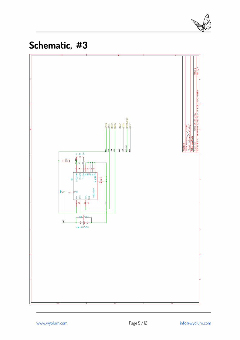
Schematic, #3
www . wyolum . com Page 5 / 12 info @ wyolum . com

Schematic, #4
www . wyolum . com Page 6 / 12 info @ wyolum . com

Physical Interfaces
NOTE : Picture shows the prototype Beta boards. Final production boards do not have the cutout, and GPS header is re-positioned.
www . wyolum . com Page 7 / 12 info @ wyolum . com
I/O HI/O H
I/O LI/O L
GPIOGPIO
FTDIFTDI
GPSGPS
ISPISPA_REFA_REF
Analog A3,A4,A5 with5V0 and GND
Analog A3,A4,A5 with5V0 and GND
Analog A0,A1,A2 with3V3 and GND
Analog A0,A1,A2 with3V3 and GND
Power/RSTPower/RST
Servo with5V0 and GNDServo with
5V0 and GND
uSD CarduSD Card
V_LinkON=Power from Ras-Pi
V_LinkON=Power from Ras-Pi
RST SwitchRST Switch
Blink LEDBlink LED5V0/3V3
LEDs5V0/3V3
LEDs
GPIOGPIO
CR1632for RTCCR1632for RTC
uUSB InputuUSB Input
JTAGnot used
JTAGnot used

Physical Interfaces, Description( RED Markers point to Pin # 1 of each header )
HEADER POWER
1. NC2. 5V03. RST4. 3V35. 5V06. GND7. GND8. Vin (Note : 5V only)
HEADER ANALOG
1. A0 : 3V3 : GND2. A1 : 3V3 : GND3. A2 : 3V3 : GND4. A3 : 5V0 : GND5. A4 : 5V0 : GND , SDA6. A5 : 5V0 : GND , SCL
HEADER's ISP and AREF
1. 1. MISO 2. 5V03. SCK 4. MOSI5. RST 6. GND
1. 3V32. AREF3. 5V0
www . wyolum . com Page 8 / 12 info @ wyolum . com
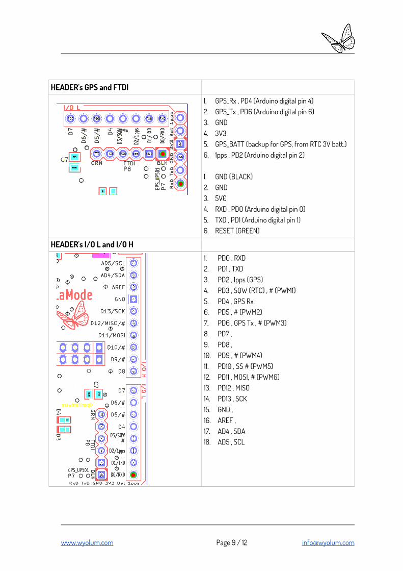
HEADER's GPS and FTDI
1. GPS_Rx , PD4 (Arduino digital pin 4)2. GPS_Tx , PD6 (Arduino digital pin 6)3. GND4. 3V35. GPS_BATT (backup for GPS, from RTC 3V batt.)6. 1pps , PD2 (Arduino digital pin 2)
1. GND (BLACK)2. GND3. 5V04. RXD , PD0 (Arduino digital pin 0)5. TXD , PD1 (Arduino digital pin 1)6. RESET (GREEN)
HEADER's I/O L and I/O H
1. PD0 , RXD2. PD1 , TXD3. PD2 , 1pps (GPS)4. PD3 , SQW (RTC) , # (PWM1)5. PD4 , GPS Rx6. PD5 , # (PWM2)7. PD6 , GPS Tx , # (PWM3)8. PD7 , 9. PD8 , 10. PD9 , # (PWM4)11. PD10 , SS # (PWM5)12. PD11 , MOSI, # (PWM6)13. PD12 , MISO14. PD13 , SCK15. GND ,16. AREF ,17. AD4 , SDA18. AD5 , SCL
www . wyolum . com Page 9 / 12 info @ wyolum . com

HEADER GPIO
1. Rpi_3V3 2. Rpi_5V03. Rpi_SDA , SDA0 4. NC5. Rpi_SCL , SCL0 6. GND7. NC , GPIO4 8. Rpi_Tx9. NC 10. Rpi_Rx11. NC , GPIO 0 12. Rpi_RST , GPIO 113. NC , GPIO 2 14. NC15. NC , GPIO 3 16. NC , GPIO 417. NC 18. NC , GPIO 519. Rpi_MOSI 20. NC21. Rpi_MISO 22. NC , GPIO 623. Rpi_SCK 24. NC , SPI_CE025. NC 26. NC , SPI_CE1
MICRO HEADER 5V-LINK
1. 5V02. Rpi_5V03. NC
If ON, AlaMode is powered via Rpi 5V0If OFF, AlaMode needs to be powered via P12, u-USB
socket
www . wyolum . com Page 10 / 12 info @ wyolum . com

HEADER SERVO
1. PWM1 , PD3 5V_SERVO GND_SERVO2. PWM2 , PD5 5V_SERVO GND_SERVO3. PWM3 , PD6 5V_SERVO GND_SERVO4. PWM4 , PD9 5V_SERVO GND_SERVO5. PWM5 , PD10 5V_SERVO GND_SERVO6. PWM6 , PD11 5V_SERVO GND_SERVO7. 5V_INT 5V_SERVO GND_SERVO8. 5V_INT 5V_SERVO GND_SERVO
ERRATA : PWM6 = PD11 , MOSI (NOT PD12)
To power Servos via AlaMode 5V0 supply (internal mode), fix shorting links/jumpers between Pin 7 (5V_INT) and 5V_SERVO and Pin 8 (5V_INT) and 5V_SERVOas marked here (red rectangles)
(Note : Single jumper will work too. Dual jumpers allow higher current capacity)
To power Servos via External 5V supply (external mode), connect 5V_SERVO to 5V_Ext5V_SERVO to 5V_ExtandGND to GND_ExtGND to GND_Extas marked here (red / gray rectangles)
(Note : Single connections will work too. Dual connections allow higher current capacity)
www . wyolum . com Page 11 / 12 info @ wyolum . com
5V_Ext5V_Ext
GND_ExtGND_Ext

LINKS● website : www . wyolum . com ● e-mail : info @ wyolum . com ● forum : http://wyolum.com/forum/forumdisplay.php?fid=14 ● Git Repo : https://github.com/wyolum/alamode ● Arduino : http :// www . arduino . cc /
www . wyolum . com Page 12 / 12 info @ wyolum . com


