
All IDOT Design Guides have been updated to reflect the release of the 2017 AASHTO LRFD Bridge Design Specification, 8th Edition. The following is a summary of the major changes that have been incorporated into the PPC Deck Beam Design Guide.
• The equation for the concrete modulus of elasticity, Ec, has been modified.

Design Guides 3.5 - LRFD PPC Deck Beam Design
May 2019 Page 3.4-1
3.5 LRFD PPC Deck Beam Design
This design guide focuses on the LRFD design of PPC Deck Beams. The design procedure is
presented first followed by an example. All Article and Equation references are to the LRFD
code unless noted otherwise.
There are twelve standard beam cross sections supported by the Department. These are
11x48, 11x52, 17x36, 17x48, 21x36, 21x48, 27x36, 27x48, 33x36, 33x48, 42x36 and 42x48.
Standard strand patterns for LRFD designs have been developed and are provided in Bridge
Manual (BM) Tables 3.5.3-1 thru 3.5.3-6. All other reinforcement details (shear reinforcement,
splitting steel, top slab reinforcement, etc.) have been standardized and are shown on the base
sheets. Aids for detailing the end blocks and designing lifting loops are shown in BM Figures
3.5.9-3 and 3.5.9-4.
The main items a designer has to calculate are distribution factors, moment envelopes,
prestress losses, temporary stresses, service stresses and resisting moment capacities; all of
which are used to determine the required strand pattern.
The sign convention used in the examples was noted by labeling negative results with “tension”
and positive results with “compression” unless otherwise noted.
Design Guides 3.5 - LRFD PPC Deck Beam Design
Page 3.4-2 May 2019
LRFD Design Procedure, Equations and Outline
Transverse Ties
Transverse ties are used on all deck beams except the 11 inch deep sections which are too
shallow to accommodate the ties. The 11 inch beams rely mainly on the dowel rods at fixed
substructure units and side retainers at expansion substructure units in lieu of the ties. For
17 through 42 inch beams transverse ties are placed along the skew throughout the span
with a uniform spacing. The beam base sheets show the standard configuration for a
transverse tie diaphragm. The number of ties is determined by the following formula:
Number ties = 1125
L≥
− rounded up to the nearest integer
Where:
L = span of beam (ft.)
Dead Loads
Calculate the dead loads on a single beam such as the beam self weight, wearing surface,
future wearing surface, parapets or railing and any other dead loads on the bridge and
group them into their appropriate types DC and DW. Distribution of railings or parapets shall
be spread over three beams. Sidewalks and medians shall be distributed over the number
of beams they cover plus one or two depending on if there are beams on both sides.
The beam self weight is non-uniform for all beams except the 11 inch sections. The weights
for both the solid and voided sections of each beam size can be found in BM Figure 3.5.9-4.
Typically a designer would use the net section uniform load in conjunction with a series of
point loads that would represent the solid portions at the transverse tie diaphragms and end
blocks. The solid part at the end blocks can be ignored for moment calculations however
they should be included for the lifting loop and substructure design. See Figure 1 for the
loading diagrams used to calculate the moment due to beam self weight with one to four
transverse tie diaphragms.

Design Guides 3.5 - LRFD PPC Deck Beam Design
May 2019 Page 3.4-3
Figure 1
Formulas for Moment due to Beam Self Weight
a) Mb = 4
LP
8
Lw T2
net +
b) Mb = TT
2net LP8
Lw+
c) Mb = TT
2net LP28
Lw+
d) Mb = TT
2net LP38
Lw+
Design Guides 3.5 - LRFD PPC Deck Beam Design
Page 3.4-4 May 2019
In which:
PT = ( )
( )netsolid wwskewcos
.ft2−
Where:
Mb = bending moment due to beam self weight (kip-ft.)
wnet = weight per unit length of the section of the beam with voids (kip/ft.)
wsolid = weight per unit length of the section of the beam without voids
(kip/ft.)
PT = weight of transverse tie diaphragm (kips)
LT = transverse tie spacing (ft.)
L = span of beam (ft.)
Section Properties
Deck beams are always designed as non-composite sections even if a reinforced concrete
overlay is used. The section properties for each beam section are provided in BM Table
3.5.4-1.
Modulus of Elasticity
The modulus of elasticity for concrete shall be determined from the following formulas:
Eci = 33.0ci
0.2
c1 'fwK000,120 (Eq. 5.4.2.4-1)
Ec = 33.0c
0.2
c1 'fwK000,120
Where:
Eci = modulus of elasticity of concrete at transfer (ksi)
Ec = modulus of elasticity of concrete (ksi)
K1 = aggregate modification factor, taken as 1.0
wc = unit weight of concrete, as per Table 3.5.1-1, this is taken as 0.140 +
0.001f’c, or 0.146 kcf for 6 ksi concrete. However, it is typical to use either
0.150 kcf or 0.145 kcf.
f’ci = specified compressive strength of concrete at time of initial loading or
prestressing (ksi)
Design Guides 3.5 - LRFD PPC Deck Beam Design
May 2019 Page 3.4-5
f’c = specified compressive strength of concrete for use in design (ksi)
Distribution Factors for Moment
Live load moments shall be distributed according to Article 4.6.2.2. See Table 4.6.2.2.2b-1
under “Concrete Beams used in Multibeam Decks”, cross section (g) “connected only
enough to prevent relative vertical displacement at the interface”. It should be noted that the
department does not use the distribution factors associated with cross section (f) for
reinforced concrete overlays. The Department also does not consider exterior beam
distribution factors in Table 4.6.2.2.2d-1 or reduction of distribution factors in Table
4.6.2.2.2e-1. The distribution equation below can be used for both the final and staged
construction cases.
Regardless of the number of loaded lanes the distribution factor equals:
g = D
S
In which:
D = ( )2
LL C2.01N4.1N5.11 −+− when C≤5
LN5.11 − when C>5
C = KL
WK ≤
K = ( )
J
I1 µ+
Where:
g = distribution factor
S = beam spacing (ft.)
D = width of distribution per lane (ft.)
NL = number of design lanes as specified in Article 3.6.1.1.1
C = stiffness parameter
K = constant for different types of construction
W = edge-to-edge width of bridge (ft.)
Design Guides 3.5 - LRFD PPC Deck Beam Design
Page 3.4-6 May 2019
L = span of beam (ft.)
I = moment of inertia (in.4)
µ = Poisson’s ratio, assumed to be 0.2
J = St. Venant’s torsional inertia (in.4)
The distribution factor for fatigue evaluation equals the factor calculated above divided
by the multi presence factor for one lane. See BM Section 3.3.1.
Design Moment
Since deck beam bridges in Illinois are typically not designed as continuous structures the
moments can be calculated by hand or by using software written for the task.
Strand Pattern Selection
The planning selection charts located in BM Section 2.3.6.1.2 can be used to determine a
trial strand pattern. The properties of the trial strand pattern can be found in BM Tables
3.5.3-1 through 3.5.3-6.
Prestress Losses (5.9.3)
Calculate prestress losses.
Total Loss of Prestress (5.9.3.1)
∆fpT = ∆fpES + ∆fpLT (Eq. 5.9.3.1-1)
Where:
∆fpT = total loss (ksi)
∆fpES = loss in prestressing steel due to elastic shortening (instantaneous losses)
(ksi)
∆fpLT = losses due to long term shrinkage and creep of concrete, and relaxation
of the steel (ksi)
Design Guides 3.5 - LRFD PPC Deck Beam Design
May 2019 Page 3.4-7
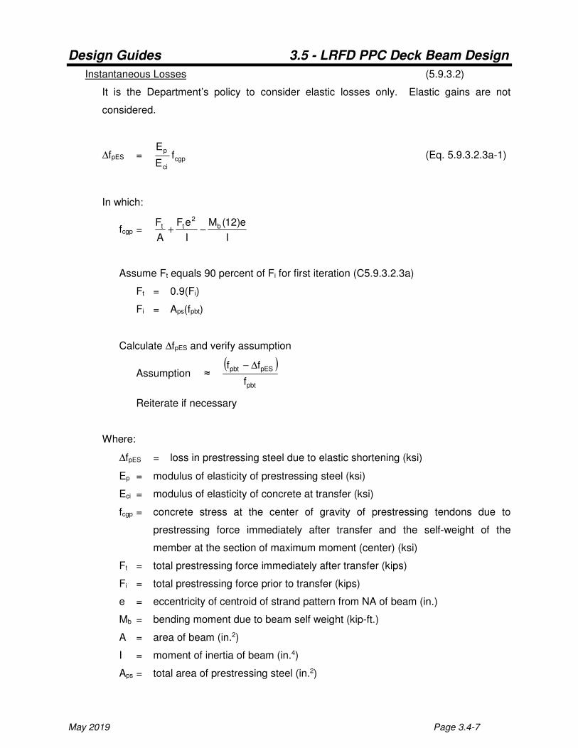
Instantaneous Losses (5.9.3.2)
It is the Department’s policy to consider elastic losses only. Elastic gains are not
considered.
∆fpES = cgp
ci
pf
E
E (Eq. 5.9.3.2.3a-1)
In which:
fcgp = I
e)12(M
I
eF
A
F b2
tt −+
Assume Ft equals 90 percent of Fi for first iteration (C5.9.3.2.3a)
Ft = 0.9(Fi)
Fi = Aps(fpbt)
Calculate ∆fpES and verify assumption
Assumption ≈ ( )
pbt
pESpbt
f
ff ∆−
Reiterate if necessary
Where:
∆fpES = loss in prestressing steel due to elastic shortening (ksi)
Ep = modulus of elasticity of prestressing steel (ksi)
Eci = modulus of elasticity of concrete at transfer (ksi)
fcgp = concrete stress at the center of gravity of prestressing tendons due to
prestressing force immediately after transfer and the self-weight of the
member at the section of maximum moment (center) (ksi)
Ft = total prestressing force immediately after transfer (kips)
Fi = total prestressing force prior to transfer (kips)
e = eccentricity of centroid of strand pattern from NA of beam (in.)
Mb = bending moment due to beam self weight (kip-ft.)
A = area of beam (in.2)
I = moment of inertia of beam (in.4)
Aps = total area of prestressing steel (in.2)

Design Guides 3.5 - LRFD PPC Deck Beam Design
Page 3.4-8 May 2019
fpbt = stress in prestressing steel immediately prior to transfer (ksi)
Time Dependent Losses (5.9.3.3)
The AASHTO LRFD Bridge Design Specifications contains two methods for calculating
time dependent losses: the "Approximate" method in Article 5.9.3.3 and the "Refined"
method in Article 5.9.3.4. The approximate method is fairly straightforward and requires
only basic information that is readily available to the designer. The refined method is
much more rigorous; the equations are difficult to follow; and information is required that
the designer does not have direct control over. Some of these variables are the time the
strands are released, the time the deck is placed and the actual concrete strength at
release. These variables require the designer to use a best-estimate guess, yet these
variables can impact the results significantly. Article 5.9.5.3 provides further clarification
for the application of the approximate and refined methods. In particular it specifies that
the refined method shall be used for members that are non-composite which would
appear applicable for deck beam structures. However, the Department has evaluated
the specifications and our details and developed the following policy:
Deck beams with a 5 inch concrete wearing surface shall use the approximate method
for time dependent losses. The Department believes the concrete wearing surface
behaves as a partially composite section with the beams even though it's not considered
to be partially composite for strength calculations. This logic is based upon the required
textured broom finish on the top surface of the beam, the D(E) bars that protrude from
the tops of the exterior beams for F-shaped barriers and Type SM railings, and because
there have been no signs of separation between the beams and the CWS on our
inventory inspections.
Deck beams with no wearing surface or a bituminous wearing surface shall also use the
approximate method for time dependent losses. However, in order to satisfy the spirit of
the code, a correction factor shall be added to the results obtained from the approximate
method to more closely match the intent of the refined method. The correction factors
are as follows:
Design Guides 3.5 - LRFD PPC Deck Beam Design
May 2019 Page 3.4-9
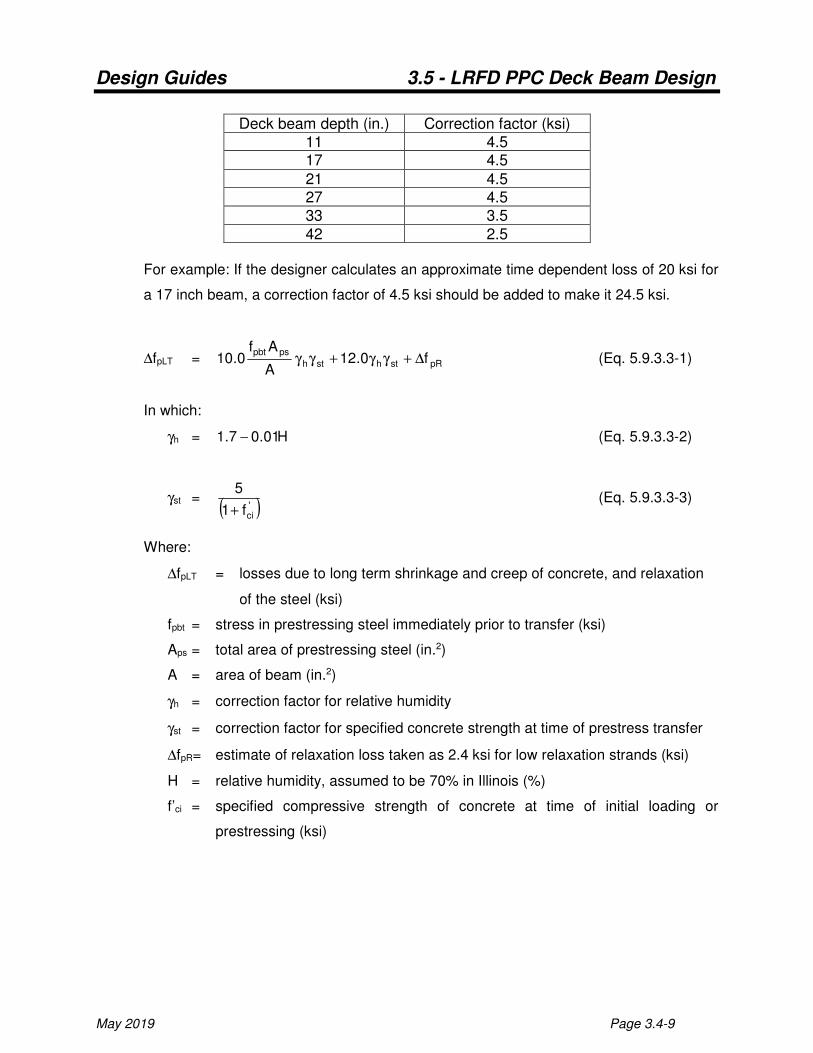
Deck beam depth (in.) Correction factor (ksi)
11 4.5 17 4.5
21 4.5 27 4.5 33 3.5
42 2.5
For example: If the designer calculates an approximate time dependent loss of 20 ksi for
a 17 inch beam, a correction factor of 4.5 ksi should be added to make it 24.5 ksi.
∆fpLT = pRsthsth
pspbtf0.12
A
Af0.10 ∆+γγ+γγ (Eq. 5.9.3.3-1)
In which:
γh = H01.07.1 − (Eq. 5.9.3.3-2)
γst = ( )'
cif1
5
+ (Eq. 5.9.3.3-3)
Where:
∆fpLT = losses due to long term shrinkage and creep of concrete, and relaxation
of the steel (ksi)
fpbt = stress in prestressing steel immediately prior to transfer (ksi)
Aps = total area of prestressing steel (in.2)
A = area of beam (in.2)
γh = correction factor for relative humidity
γst = correction factor for specified concrete strength at time of prestress transfer
∆fpR= estimate of relaxation loss taken as 2.4 ksi for low relaxation strands (ksi)
H = relative humidity, assumed to be 70% in Illinois (%)
f’ci = specified compressive strength of concrete at time of initial loading or
prestressing (ksi)

Design Guides 3.5 - LRFD PPC Deck Beam Design
Page 3.4-10 May 2019
Temporary Stresses (5.9.2.3)
Temporary stresses are checked immediately after the release of the strands when the
concrete strength, f’ci, is weakest. The force in the strands is taken to be the prestressing
force immediately after transfer, Ft.
There are three support conditions to consider during this time frame. The first occurs when
the strands are released and the beam is still setting on the prestressing bed. The second
occurs when lifting the beam out of the prestressing bed. The third occurs when placing the
beam in temporary storage at the fabrication plant. Theoretically, all three of these
conditions could take place while the concrete is most vulnerable, however the third
condition will govern for deck beams if current IDOT policies are followed. Therefore this is
the only condition checked.
For this case, the stresses need to be checked in two locations, which are at the center of
the temporary supports and at the center of the beam.
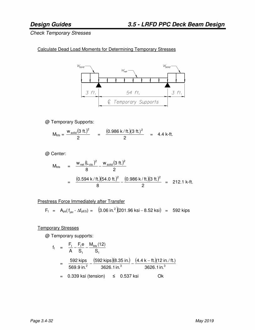
See Figure 2 for the support and loading diagram used to calculate the dead load moments
for checking temporary stresses. The weights of transverse tie diaphragms are
conservatively ignored.
Figure 2
@ Temporary Supports:
Mbts = ( )2
.ft3w2
solid
Design Guides 3.5 - LRFD PPC Deck Beam Design
May 2019 Page 3.4-11
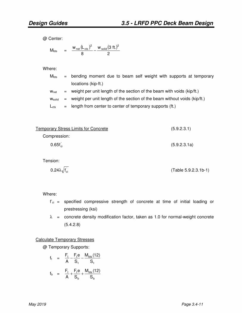
@ Center:
Mbts = ( ) ( )
2
.ft3w
8
Lw2
solid
2
ctsnet −
Where:
Mbts = bending moment due to beam self weight with supports at temporary
locations (kip-ft.)
wnet = weight per unit length of the section of the beam with voids (kip/ft.)
wsolid = weight per unit length of the section of the beam without voids (kip/ft.)
Lcts = length from center to center of temporary supports (ft.)
Temporary Stress Limits for Concrete (5.9.2.3.1)
Compression:
'cif65.0 (5.9.2.3.1a)
Tension:
'cif24.0 λ (Table 5.9.2.3.1b-1)
Where:
f’ci = specified compressive strength of concrete at time of initial loading or
prestressing (ksi)
λ = concrete density modification factor, taken as 1.0 for normal-weight concrete
(5.4.2.8)
Calculate Temporary Stresses
@ Temporary Supports:
ft = t
bts
t
tt
S
)12(M
S
eF
A
F−−
fb = b
bts
b
tt
S
)12(M
S
eF
A
F++
Design Guides 3.5 - LRFD PPC Deck Beam Design
Page 3.4-12 May 2019
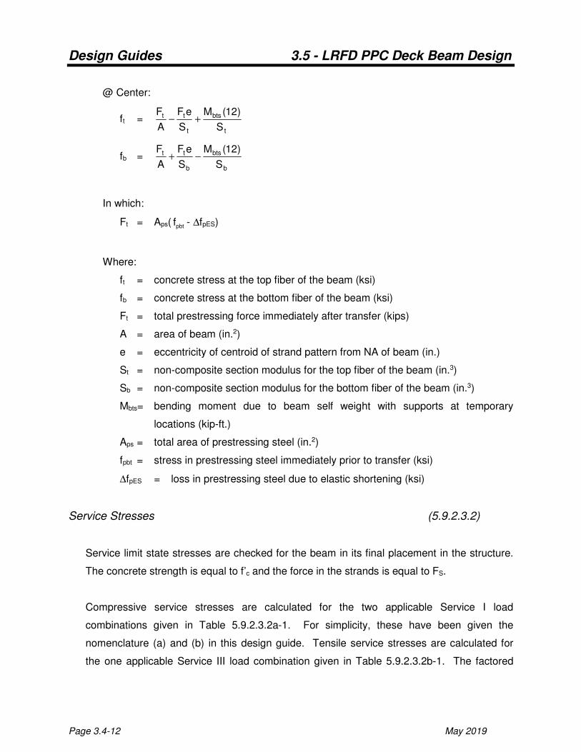
@ Center:
ft = t
bts
t
tt
S
)12(M
S
eF
A
F+−
fb = b
bts
b
tt
S
)12(M
S
eF
A
F−+
In which:
Ft = Aps( pbtf - ∆fpES)
Where:
ft = concrete stress at the top fiber of the beam (ksi)
fb = concrete stress at the bottom fiber of the beam (ksi)
Ft = total prestressing force immediately after transfer (kips)
A = area of beam (in.2)
e = eccentricity of centroid of strand pattern from NA of beam (in.)
St = non-composite section modulus for the top fiber of the beam (in.3)
Sb = non-composite section modulus for the bottom fiber of the beam (in.3)
Mbts= bending moment due to beam self weight with supports at temporary
locations (kip-ft.)
Aps = total area of prestressing steel (in.2)
fpbt = stress in prestressing steel immediately prior to transfer (ksi)
∆fpES = loss in prestressing steel due to elastic shortening (ksi)
Service Stresses (5.9.2.3.2)
Service limit state stresses are checked for the beam in its final placement in the structure.
The concrete strength is equal to f’c and the force in the strands is equal to FS.
Compressive service stresses are calculated for the two applicable Service I load
combinations given in Table 5.9.2.3.2a-1. For simplicity, these have been given the
nomenclature (a) and (b) in this design guide. Tensile service stresses are calculated for
the one applicable Service III load combination given in Table 5.9.2.3.2b-1. The factored
Design Guides 3.5 - LRFD PPC Deck Beam Design
May 2019 Page 3.4-13
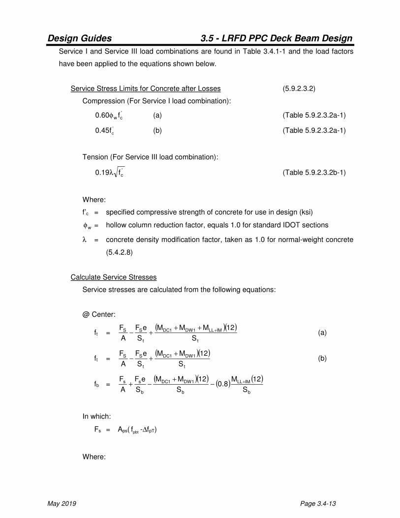
Service I and Service III load combinations are found in Table 3.4.1-1 and the load factors
have been applied to the equations shown below.
Service Stress Limits for Concrete after Losses (5.9.2.3.2)
Compression (For Service I load combination):
'cw f60.0 φ (a) (Table 5.9.2.3.2a-1)
'
cf45.0 (b) (Table 5.9.2.3.2a-1)
Tension (For Service III load combination):
'cf19.0 λ (Table 5.9.2.3.2b-1)
Where:
f’c = specified compressive strength of concrete for use in design (ksi)
wφ = hollow column reduction factor, equals 1.0 for standard IDOT sections
λ = concrete density modification factor, taken as 1.0 for normal-weight concrete
(5.4.2.8)
Calculate Service Stresses
Service stresses are calculated from the following equations:
@ Center:
ft = ( )( )
t
IMLL1DW1DC
t
SS
S
12MMM
S
eF
A
F ++++− (a)
ft = ( )( )
t
1DW1DC
t
SS
S
12MM
S
eF
A
F ++− (b)
fb = ( )( )
( )( )
b
IMLL
b
1DW1DC
b
ss
S
12M8.0
S
12MM
S
eF
A
F +−+
−+
In which:
Fs = Aps( pbtf -∆fpT)
Where:

Design Guides 3.5 - LRFD PPC Deck Beam Design
Page 3.4-14 May 2019
ft = concrete stress at the top fiber of the beam (ksi)
fb = concrete stress at the bottom fiber of the beam (ksi)
FS = total prestressing force after all losses (kips)
A = area of beam (in.2)
e = eccentricity of centroid of strand pattern from NA of beam (in.)
MDC1= unfactored non-composite dead load moment of structural components
and nonstructural attachments (kip-ft.)
MDW1= unfactored non-composite dead load moment of wearing surfaces and
utilities (kip-ft.)
MLL+IM= unfactored live load moment (HL-93) plus dynamic load allowance (kip-ft.)
St = non-composite section modulus for the top fiber of the beam (in.3)
Sb = non-composite section modulus for the bottom fiber of the beam (in.3)
Aps = total area of prestressing steel (in.2)
fpbt = stress in prestressing steel immediately prior to transfer (ksi)
∆fpT = total loss (ksi)
Fatigue Stresses (5.5.3.1)
The compressive stress due to the Fatigue I load combination and one-half the sum of
effective prestress and permanent loads shall not exceed the limit shown below. The
section properties used for calculating the compressive stress are determined based on
whether the tensile stress limit shown below is exceeded. The tensile stress is calculated
using the Fatigue I load combination plus effective prestress and permanent loads.
Fatigue Stress Limits for Concrete after Losses (5.5.3.1)
Compression:
'
cf40.0
Tension limit for determination cracking of section:
Uncracked ≤ 'cf095.0 ≤ Cracked
Where:
f’c = specified compressive strength of concrete for use in design (ksi)

Design Guides 3.5 - LRFD PPC Deck Beam Design
May 2019 Page 3.4-15
Calculate Fatigue Stresses
Fatigue stress is calculated from the following equation:
@ Center:
ft = ( )( ) ( )
t
IMFL
t
1DW1DC
t
SS
S
12M5.1
S
12MM
S
eF
A
F5.0 ++
++−
Tension stress is calculated from the following equation:
(This stress is only used to determine whether the section is considered cracked or
uncracked for fatigue evaluation only)
@ Center:
fb = ( )( )
( )( )
b
IMFL
b
1DW1DC
b
ss
S
12M5.1
S
12MM
S
eF
A
F +−+
−+
Where:
ft = concrete stress at the top fiber of the beam (ksi)
fb = concrete stress at the bottom fiber of the beam (ksi)
f’c = specified compressive strength of concrete for use in design (ksi)
FS = total prestressing force after all losses (kips)
A = area of beam (in.2)
e = eccentricity of centroid of strand pattern from NA of beam (in.)
MDC1= unfactored non-composite dead load moment of structural components
and nonstructural attachments (kip-ft.)
MDW1= unfactored non-composite dead load moment of wearing surfaces and
utilities (kip-ft.)
MFL+IM= unfactored fatigue live load moment plus dynamic load allowance (kip-ft.)
St = non-composite section modulus for the top fiber of the beam (in.3)
Sb = non-composite section modulus for the bottom fiber of the beam (in.3)
Flexural Resistance (5.6.3)
Design Guides 3.5 - LRFD PPC Deck Beam Design
Page 3.4-16 May 2019
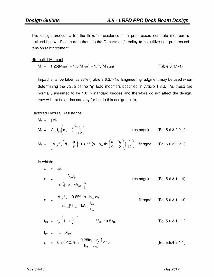
The design procedure for the flexural resistance of a prestressed concrete member is
outlined below. Please note that it is the Department’s policy to not utilize non-prestressed
tension reinforcement.
Strength I Moment
Mu = 1.25(MDC1) + 1.5(MDW1) + 1.75(MLL+IM) (Table 3.4.1-1)
Impact shall be taken as 33% (Table 3.6.2.1-1). Engineering judgment may be used when
determining the value of the “η” load modifiers specified in Article 1.3.2. As these are
normally assumed to be 1.0 in standard bridges and therefore do not affect the design,
they will not be addressed any further in this design guide.
Factored Flexural Resistance
Mr = φMn
Mn =
−
12
1
2
adfA ppsps rectangular (Eq. 5.6.3.2.2-1)
Mn = ( )
−−+
−
12
1
2
h
2
ahbbf85.0
2
adfA f
fw'cppsps flanged (Eq. 5.6.3.2.2-1)
In which:
a = β1c
c =
p
pu
ps1'c1
pups
d
fkAbf
fA
+βα
rectangular (Eq. 5.6.3.1.1-4)
c =
p
pu
psw1'c1
fw'cpups
d
fkAbf
h)bb(f85.0fA
+βα
−− flanged (Eq. 5.6.3.1.1-3)
fps =
−
p
pud
ck1f If fpe ≥ 0.5 fpu (Eq. 5.6.3.1.1-1)
fpe = fpu − ∆fpT
φ = ( )
( )0.1
25.075.075.0
cltl
clt ≤ε−ε
ε−ε+≤ (Eq. 5.5.4.2.1-1)
Design Guides 3.5 - LRFD PPC Deck Beam Design
May 2019 Page 3.4-17
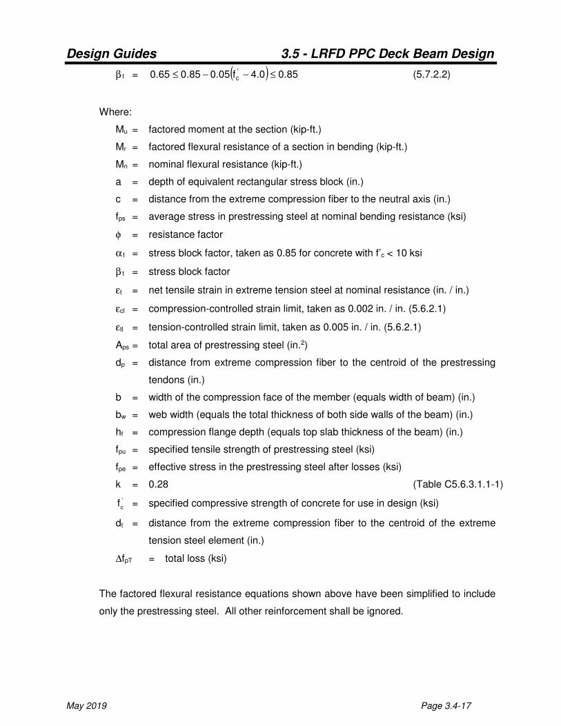
β1 = ( ) 85.00.4f05.085.065.0 'c ≤−−≤ (5.7.2.2)
Where:
Mu = factored moment at the section (kip-ft.)
Mr = factored flexural resistance of a section in bending (kip-ft.)
Mn = nominal flexural resistance (kip-ft.)
a = depth of equivalent rectangular stress block (in.)
c = distance from the extreme compression fiber to the neutral axis (in.)
fps = average stress in prestressing steel at nominal bending resistance (ksi)
φ = resistance factor
α1 = stress block factor, taken as 0.85 for concrete with f’c < 10 ksi
β1 = stress block factor
εt = net tensile strain in extreme tension steel at nominal resistance (in. / in.)
εcl = compression-controlled strain limit, taken as 0.002 in. / in. (5.6.2.1)
εtl = tension-controlled strain limit, taken as 0.005 in. / in. (5.6.2.1)
Aps = total area of prestressing steel (in.2)
dp = distance from extreme compression fiber to the centroid of the prestressing
tendons (in.)
b = width of the compression face of the member (equals width of beam) (in.)
bw = web width (equals the total thickness of both side walls of the beam) (in.)
hf = compression flange depth (equals top slab thickness of the beam) (in.)
fpu = specified tensile strength of prestressing steel (ksi)
fpe = effective stress in the prestressing steel after losses (ksi)
k = 0.28 (Table C5.6.3.1.1-1)
'
cf = specified compressive strength of concrete for use in design (ksi)
dt = distance from the extreme compression fiber to the centroid of the extreme
tension steel element (in.)
∆fpT = total loss (ksi)
The factored flexural resistance equations shown above have been simplified to include
only the prestressing steel. All other reinforcement shall be ignored.
Design Guides 3.5 - LRFD PPC Deck Beam Design
Page 3.4-18 May 2019
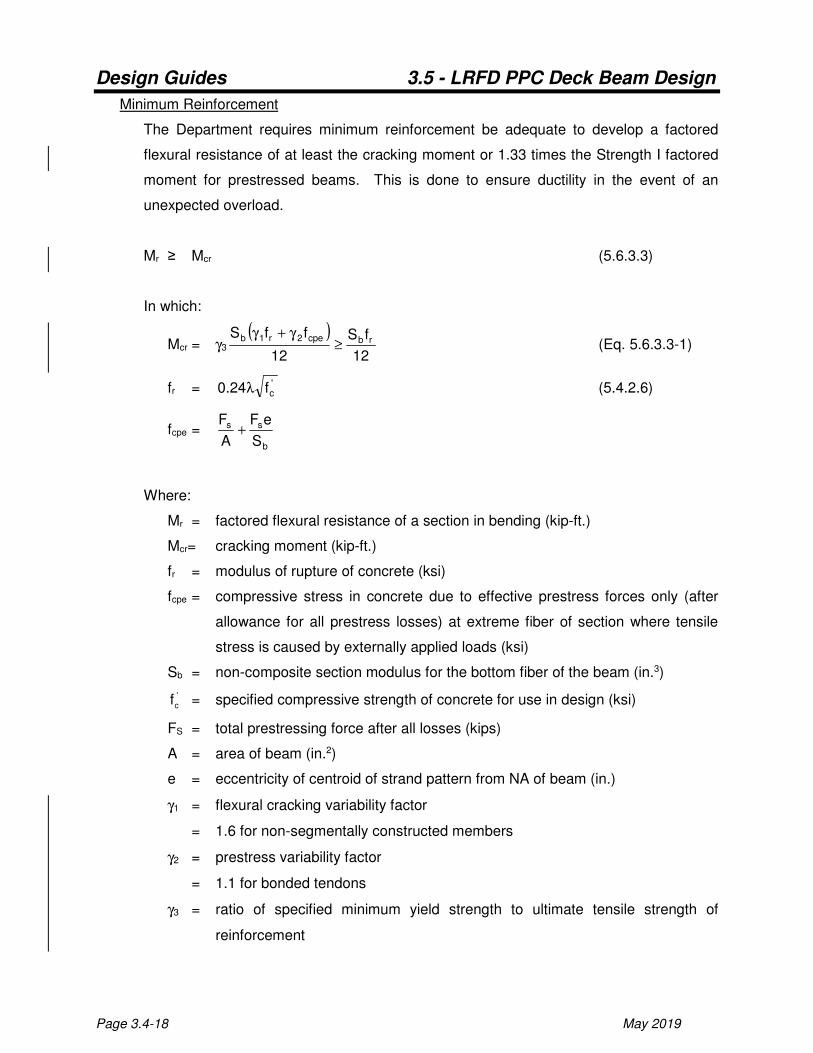
Minimum Reinforcement
The Department requires minimum reinforcement be adequate to develop a factored
flexural resistance of at least the cracking moment or 1.33 times the Strength I factored
moment for prestressed beams. This is done to ensure ductility in the event of an
unexpected overload.
Mr ≥ Mcr (5.6.3.3)
In which:
Mcr = γ3
( )12
fS
12
ffSrbcpe2r1b
≥γ+γ
(Eq. 5.6.3.3-1)
fr = 'cf24.0 λ (5.4.2.6)
fcpe = b
ss
S
eF
A
F+
Where:
Mr = factored flexural resistance of a section in bending (kip-ft.)
Mcr= cracking moment (kip-ft.)
fr = modulus of rupture of concrete (ksi)
fcpe = compressive stress in concrete due to effective prestress forces only (after
allowance for all prestress losses) at extreme fiber of section where tensile
stress is caused by externally applied loads (ksi)
Sb = non-composite section modulus for the bottom fiber of the beam (in.3)
'
cf = specified compressive strength of concrete for use in design (ksi)
FS = total prestressing force after all losses (kips)
A = area of beam (in.2)
e = eccentricity of centroid of strand pattern from NA of beam (in.)
γ1 = flexural cracking variability factor
= 1.6 for non-segmentally constructed members
γ2 = prestress variability factor
= 1.1 for bonded tendons
γ3 = ratio of specified minimum yield strength to ultimate tensile strength of
reinforcement

Design Guides 3.5 - LRFD PPC Deck Beam Design
May 2019 Page 3.4-19
= 1.00 for prestressed concrete structures
λ = lightweight concrete factor, taken as 1.0 for regular weight concrete
Design Guides 3.5 - LRFD PPC Deck Beam Design
Page 3.4-20 May 2019
Calculate Camber and Deflection
Camber, which is the result of the difference between the upward deflection caused by the
prestressing forces and the downward deflection due to the weight of the beam and overlay,
must be considered when determining the seat elevations. The top of the beam shall be set
to provide the minimum overlay thickness specified on the plans.
Camber will vary with the age of the member, primarily because of two factors; loss of
prestress which will tend to decrease the deflection, and creep which will tend to increase
the deflection. Because of this, correction factors are used in the equations for calculating
camber. Factors of 1.80 and 1.85 are used on the upward deflection caused by the
prestressing force and downward deflection due to member weight, respectively. These
factors are based on the PCI Design Handbook for the time at erection and have been
incorporated into the equations shown below.
The deflection due to the transverse tie diaphragms need only be considered for members
60 feet and longer.
Initial Resultant Camber
Camber = Dcp - Dcb
In which:
Dcp = ( )
( )80.1IE8
eL12F
ci
2
t
Dcb = ( )
( ))85.1(
IE12384
L12w5
ci
4
net (uniform net section weight per foot)
Dcb = ( )
)85.1(IE48
L12P
ci
3
T (one transverse tie point load at center)
Dcb= ( )
( ) ( )[ ] )85.1(L124L123IE24
12LP 2
tt
2
ci
ttT − (two transverse tie point loads
symmetrically placed)
Where:
Dcp = upward deflection due to prestressing (in.)

Design Guides 3.5 - LRFD PPC Deck Beam Design
May 2019 Page 3.4-21
Dcb = downward deflection due to beam weight (in.)
Ft = total prestressing force immediately after transfer (kips)
L = span length (ft.)
e = eccentricity of centroid of strand pattern from NA of beam (in.)
Eci = modulus of elasticity of concrete at transfer (ksi)
I = moment of inertia of beam (in.4)
wnet = weight per unit length of the section of the beam with voids (kip/ft.)
PT = weight of transverse tie diaphragm (kips)
Ltt = distance from support to transverse tie (ft.)
Final Resultant Camber for Computing Bearing Seat Elevations
The dead loads to be considered for adjusting the grade line are those which will
appreciably increase the downward deflection of the beams after they have been
erected. This load is the weight of the initial wearing surface. The weight of future
wearing surface is not included.
Normally, the deflection caused by the weight of curbs and rails is insignificant and can
be disregarded. In cases where they might appear significant, the above dead loads
should be included when adjusting the grade line for dead load deflections.
Camber = Dcp - Dcb - Dws
In which:
Dws = ( )
( ) IE12384
L12w5
c
4
ws
Where:
Dcp = upward deflection due to prestressing (in.)
Dcb = downward deflection due to beam weight (in.)
Dws = downward deflection due to wearing surface (in.)
wws = weight per unit length of the wearing surface (kip/ft.)
L = span length (ft.)
Ec = modulus of elasticity of concrete (ksi)
I = moment of inertia of beam (in.4)

Design Guides 3.5 - LRFD PPC Deck Beam Design
Page 3.4-22 May 2019
Downward Deflections Due to Overlay Weight for Adjusting Grade Elevations
@0.25 point = 0.7125Dws
@0.50 point = Dws
@0.75 point = 0.7125Dws
Design Guides 3.5 - LRFD PPC Deck Beam Design
May 2019 Page 3.4-23
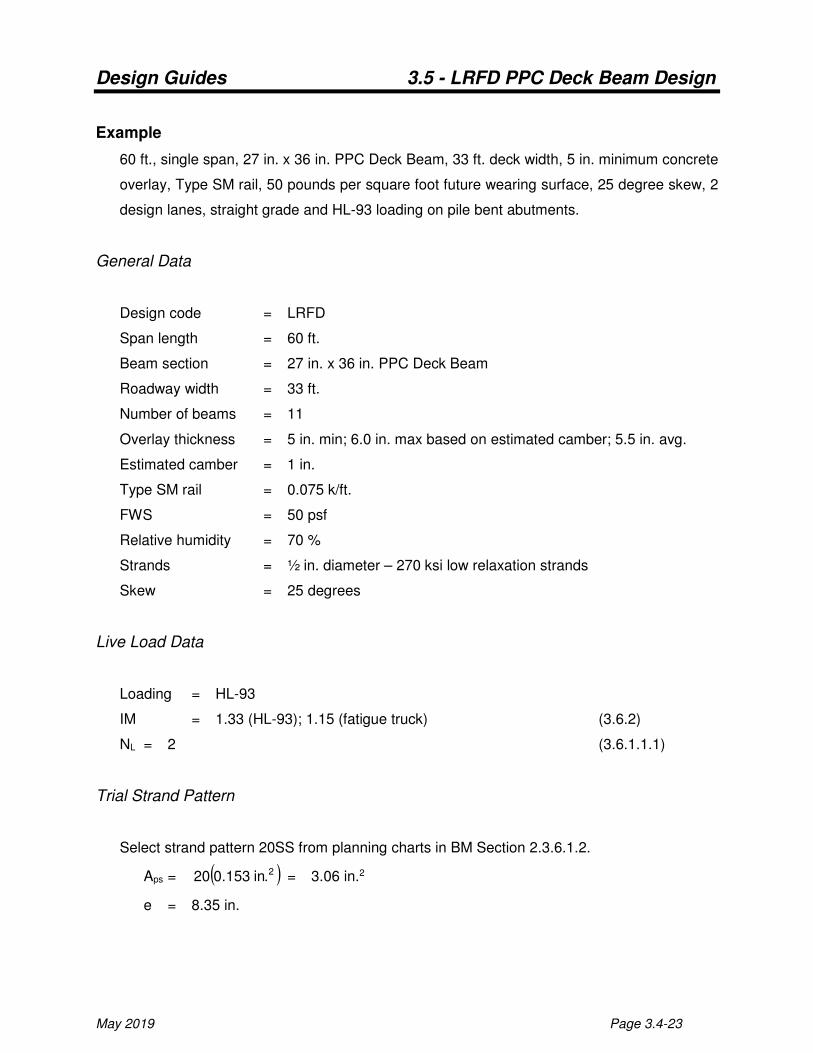
Example
60 ft., single span, 27 in. x 36 in. PPC Deck Beam, 33 ft. deck width, 5 in. minimum concrete
overlay, Type SM rail, 50 pounds per square foot future wearing surface, 25 degree skew, 2
design lanes, straight grade and HL-93 loading on pile bent abutments.
General Data
Design code = LRFD
Span length = 60 ft.
Beam section = 27 in. x 36 in. PPC Deck Beam
Roadway width = 33 ft.
Number of beams = 11
Overlay thickness = 5 in. min; 6.0 in. max based on estimated camber; 5.5 in. avg.
Estimated camber = 1 in.
Type SM rail = 0.075 k/ft.
FWS = 50 psf
Relative humidity = 70 %
Strands = ½ in. diameter – 270 ksi low relaxation strands
Skew = 25 degrees
Live Load Data
Loading = HL-93
IM = 1.33 (HL-93); 1.15 (fatigue truck) (3.6.2)
NL = 2 (3.6.1.1.1)
Trial Strand Pattern
Select strand pattern 20SS from planning charts in BM Section 2.3.6.1.2.
Aps = ( )2.in153.020 = 3.06 in.2
e = 8.35 in.
Design Guides 3.5 - LRFD PPC Deck Beam Design
Page 3.4-24 May 2019
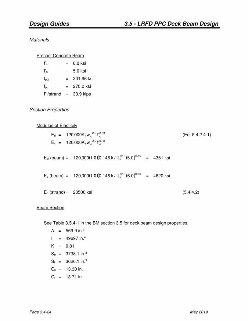
Materials
Precast Concrete Beam
f’c = 6.0 ksi
f’ci = 5.0 ksi
fpbt = 201.96 ksi
fpu = 270.0 ksi
Fi/strand = 30.9 kips
Section Properties
Modulus of Elasticity
Eci = 33.0ci
0.2c1 'fwK000,120 (Eq. 5.4.2.4-1)
Ec = 33.0c
0.2c1 'fwK000,120
Eci (beam) = ( )( ) ( ) 33.00.20.5.ft/k146.00.1000,120 = 4351 ksi
Ec (beam) = ( )( ) ( ) 33.00.20.6.ft/k146.00.1000,120 = 4620 ksi
Ep (strand) = 28500 ksi (5.4.4.2)
Beam Section
See Table 3.5.4-1 in the BM section 3.5 for deck beam design properties.
A = 569.9 in.2
I = 49697 in.4
K = 0.81
Sb = 3738.1 in.3
St = 3626.1 in.3
Cb = 13.30 in.
Ct = 13.71 in.
Design Guides 3.5 - LRFD PPC Deck Beam Design
May 2019 Page 3.4-25
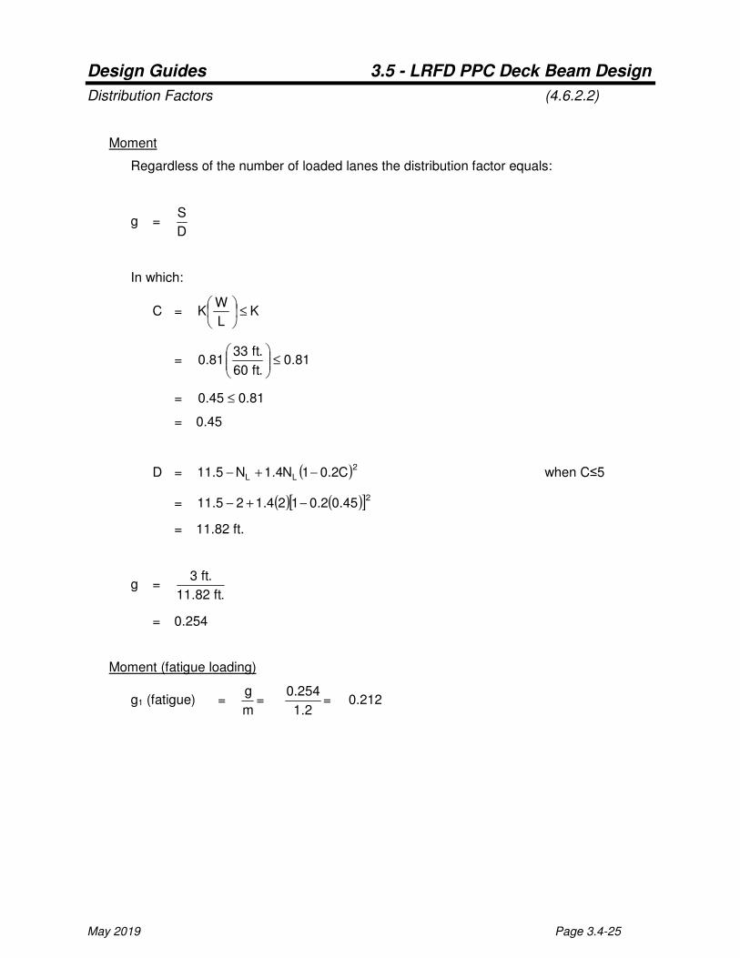
Distribution Factors (4.6.2.2)
Moment
Regardless of the number of loaded lanes the distribution factor equals:
g = D
S
In which:
C = KL
WK ≤
= 81.0.ft60
.ft3381.0 ≤
= 81.045.0 ≤
= 0.45
D = ( )2LL C2.01N4.1N5.11 −+− when C≤5
= ( ) ( )[ ]245.02.0124.125.11 −+−
= 11.82 ft.
g = .ft82.11
.ft3
= 0.254
Moment (fatigue loading)
g1 (fatigue) = m
g=
2.1
254.0= 0.212
Design Guides 3.5 - LRFD PPC Deck Beam Design
Page 3.4-26 May 2019
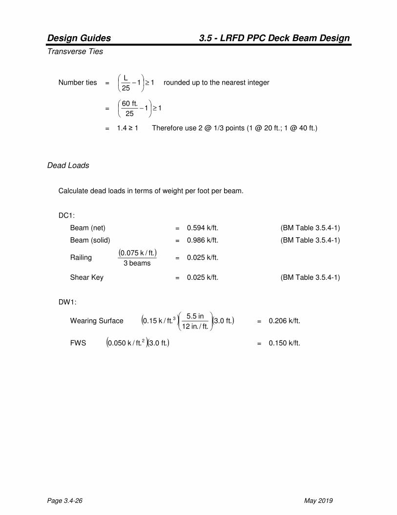
Transverse Ties
Number ties = 1125
L≥
− rounded up to the nearest integer
= 1125
.ft60≥
−
= 1.4 ≥ 1 Therefore use 2 @ 1/3 points (1 @ 20 ft.; 1 @ 40 ft.)
Dead Loads
Calculate dead loads in terms of weight per foot per beam.
DC1:
Beam (net) = 0.594 k/ft. (BM Table 3.5.4-1)
Beam (solid) = 0.986 k/ft. (BM Table 3.5.4-1)
Railing ( )
beams3
.ft/k075.0 = 0.025 k/ft.
Shear Key = 0.025 k/ft. (BM Table 3.5.4-1)
DW1:
Wearing Surface ( ) ( ).ft0.3.ft/.in12
in5.5.ft/k15.0 3
= 0.206 k/ft.
FWS ( )( ).ft0.3.ft/k050.0 2 = 0.150 k/ft.
Design Guides 3.5 - LRFD PPC Deck Beam Design
May 2019 Page 3.4-27
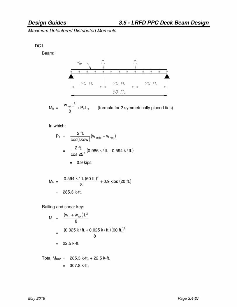
Maximum Unfactored Distributed Moments
DC1:
Beam:
Mb = TT
2net LP8
Lw+ (formula for 2 symmetrically placed ties)
In which:
PT = ( )
( )netsolid wwskewcos
.ft2−
= ( ).ft/k594.0.ft/k986.025cos
.ft2o
−
= 0.9 kips
Mb = ( ) ( ).ft20kips9.0
8
.ft60.ft/k594.02
+
= 285.3 k-ft.
Railing and shear key:
M = ( )
8
Lww 2skr +
= ( ) ( )
8
.ft60.ft/k025.0.ft/k025.02
+
= 22.5 k-ft.
Total MDC1 = 285.3 k-ft. + 22.5 k-ft.
= 307.8 k-ft.
Design Guides 3.5 - LRFD PPC Deck Beam Design
Page 3.4-28 May 2019
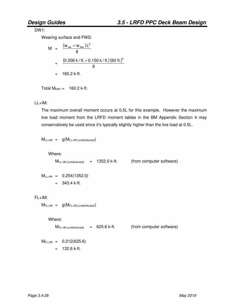
DW1:
Wearing surface and FWS:
M = ( )
8
Lww 2fwsws +
= ( ) ( )
8
.ft60.ft/k150.0.ft/k206.02
+
= 160.2 k-ft.
Total MDW1 = 160.2 k-ft.
LL+IM:
The maximum overall moment occurs at 0.5L for this example. However the maximum
live load moment from the LRFD moment tables in the BM Appendix Section 4 may
conservatively be used since it’s typically slightly higher than the live load at 0.5L.
MLL+IM = g(MLL+IM (undistributed))
Where:
MLL+IM (undistributed) = 1352.0 k-ft. (from computer software)
MLL+IM = 0.254(1352.0)
= 343.4 k-ft.
FL+IM:
MFL+IM = g(MFL+IM (undistributed))
Where:
MFL+IM (undistributed) = 625.6 k-ft. (from computer software)
MFL+IM = 0.212(625.6)
= 132.6 k-ft.
Design Guides 3.5 - LRFD PPC Deck Beam Design
May 2019 Page 3.4-29
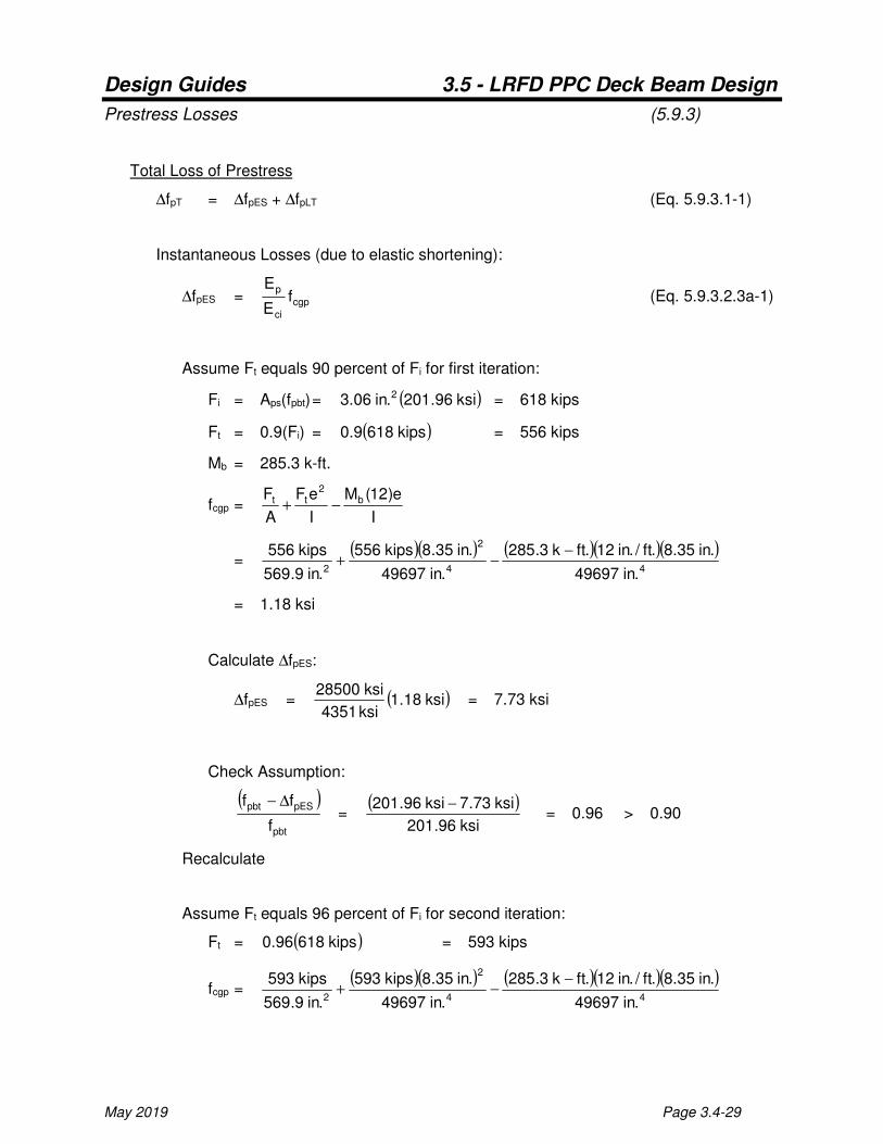
Prestress Losses (5.9.3)
Total Loss of Prestress
∆fpT = ∆fpES + ∆fpLT (Eq. 5.9.3.1-1)
Instantaneous Losses (due to elastic shortening):
∆fpES = cgp
ci
pf
E
E (Eq. 5.9.3.2.3a-1)
Assume Ft equals 90 percent of Fi for first iteration:
Fi = Aps(fpbt) = ( )ksi96.201.in06.3 2 = 618 kips
Ft = 0.9(Fi) = ( )kips6189.0 = 556 kips
Mb = 285.3 k-ft.
fcgp = I
e)12(M
I
eF
A
F b2
tt −+
= ( )( ) ( )( )( )
44
2
2 .in49697
.in35.8.ft/.in12.ftk3.285
.in49697
.in35.8kips556
.in9.569
kips556 −−+
= 1.18 ksi
Calculate ∆fpES:
∆fpES = ( )ksi18.1ksi4351
ksi28500 = 7.73 ksi
Check Assumption:
( )
pbt
pESpbt
f
ff ∆− =
( )ksi96.201
ksi73.7ksi96.201 − = 0.96 > 0.90
Recalculate
Assume Ft equals 96 percent of Fi for second iteration:
Ft = ( )kips61896.0 = 593 kips
fcgp = ( )( ) ( )( )( )
44
2
2 .in49697
.in35.8.ft/.in12.ftk3.285
.in49697
.in35.8kips593
.in9.569
kips593 −−+
Design Guides 3.5 - LRFD PPC Deck Beam Design
Page 3.4-30 May 2019
= 1.30 ksi
Calculate ∆fpES:
∆fpES = ( )ksi30.1ksi4351
ksi28500 = 8.52 ksi
Check Assumption:
( )
pbt
pESpbt
f
ff ∆− =
( )ksi96.201
ksi52.8ksi96.201 − = 0.96 Ok
Time Dependent Losses:
∆fpLT = pRsthsth
pspbtf0.12
A
Af0.10 ∆+γγ+γγ (Eq. 5.9.3.3-1)
In which:
γh = H01.07.1 − = ( )7001.07.1 − = 1.0 (Eq. 5.9.3.3-2)
γst = ( )'
cif1
5
+ =
( )ksi51
5
+ = 0.833 (Eq. 5.9.3.3-3)
∆fpR= 2.4 ksi
∆fpLT = ( )( )( )( ) ( )( ) ksi4.2833.00.10.12833.00.1
.in9.569
.in06.3ksi96.2010.10
2
2
++ = 21.43 ksi
∆fpT = ∆fpES + ∆fpLT = ksi43.21ksi52.8 + = 29.95 ksi
%Loss = ksi96.201
ksi95.29 = 14.8 %

Design Guides 3.5 - LRFD PPC Deck Beam Design
May 2019 Page 3.4-31
Stress Limits for Concrete
Temporary stresses (5.9.4.1)
Compression:
'cif65.0 = ( )ksi0.565.0 = 3.25 ksi
Tension:
'cif24.0 λ = ( ) ksi0.50.124.0 = 0.537 ksi
Service stresses after losses (5.9.4.2)
Compression (For Service I load combination):
'cw f60.0 φ = ( )( )ksi0.60.160.0 = 3.6 ksi (a)
'
cf45.0 = ( )ksi0.645.0 = 2.7 ksi (b)
Tension (For Service III load combination):
'cf19.0 λ = ( ) ksi0.60.119.0 = 0.465 ksi
Fatigue stresses after losses (5.5.3.1)
Compression (For Fatigue I load combination):
'
cf40.0 = ( )ksi0.640.0 = 2.40 ksi
Tension limit for determination of cracking of section:
Uncracked ≤ 'cf095.0 ≤ Cracked
ksi0.6095.0 = 0.233 ksi
Design Guides 3.5 - LRFD PPC Deck Beam Design
Page 3.4-32 May 2019
Check Temporary Stresses
Calculate Dead Load Moments for Determining Temporary Stresses
@ Temporary Supports:
Mbts = ( )2
.ft3w2
solid = ( )
2
.)ft3(.ft/k986.0 2
= 4.4 k-ft.
@ Center:
Mbts = ( ) ( )
2
.ft3w
8
Lw2
solid2
ctsnet −
= ( )( ) ( )( )
2
.ft3.ft/k986.0
8
.ft0.54.ft/k594.022
− = 212.1 k-ft.
Prestress Force Immediately after Transfer
Ft = Aps( pbtf - ∆fpES) = ( )( )ksi52.8ksi96.201.in06.3 2 − = 592 kips
Temporary Stresses
@ Temporary supports:
ft = t
bts
t
tt
S
)12(M
S
eF
A
F−−
= ( )( ) ( )
332 .in1.3626
.)ft/.in12(.ftk4.4
.in1.3626
.in35.8kips592
.in9.569
kips592 −−−
= 0.339 ksi (tension) ≤ 0.537 ksi Ok

Design Guides 3.5 - LRFD PPC Deck Beam Design
May 2019 Page 3.4-33
fb = b
bts
b
tt
S
)12(M
S
eF
A
F++
= ( )( ) ( )
332 .in1.3738
.)ft/.in12(.ftk4.4
.in1.3738
.in35.8kips592
.in9.569
kips592 −++
= 2.375 ksi (comp.) ≤ 3.000 ksi Ok
@ Center:
ft = t
bts
t
tt
S
)12(M
S
eF
A
F+−
= ( )( ) ( )
332 .in1.3626
.)ft/.in12(.ftk1.212
.in1.3626
.in35.8kips592
.in9.569
kips592 −+−
= 0.377 ksi (comp.) ≤ 3.000 ksi Ok
fb = b
bts
b
tt
S
)12(M
S
eF
A
F−+
= ( )( ) ( )
332 .in1.3738
.)ft/.in12(.ftk1.212
.in1.3738
.in35.8kips592
.in9.569
kips592 −−+
= 1.680 ksi (comp.) ≤ 3.000 ksi Ok
Design Guides 3.5 - LRFD PPC Deck Beam Design
Page 3.4-34 May 2019
Design Positive Moment Region
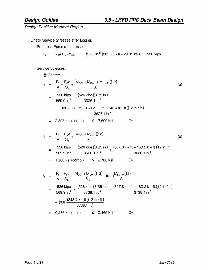
Check Service Stresses after Losses
Prestress Force after Losses:
Fs = Aps( pbtf -∆fpT) = ( )( )ksi95.29ksi96.201.in06.3 2 − = 526 kips
Service Stresses:
@ Center:
ft = ( )( )
t
IMLL1DW1DC
t
SS
S
12MMM
S
eF
A
F ++++− (a)
= 2.in9.569
kips526 −
( )( )3.in1.3626
.in35.8kips526
+ ( )( )
3.in1.3626
.ft/.in12.ftk4.343.ftk2.160.ftk8.307 −+−+−
= 2.397 ksi (comp.) ≤ 3.600 ksi Ok
ft = ( )( )
t
1DW1DC
t
SS
S
12MM
S
eF
A
F ++− (b)
= 2.in9.569
kips526 −
( )( )3.in1.3626
.in35.8kips526 +
( )( )3.in1.3626
.ft/.in12.ftk2.160.ftk8.307 −+−
= 1.260 ksi (comp.) ≤ 2.700 ksi Ok
fb = ( )( )
( )( )
b
IMLL
b
1DW1DC
b
ss
S
12M8.0
S
12MM
S
eF
A
F +−+
−+
= 2.in9.569
kips526 +
( )( )3.in1.3738
.in35.8kips526 −
( )( )3.in1.3738
.ft/.in12.ftk2.160.ftk8.307 −+−
− ( ) ( )( )3.in1.3738
.ft/.in12.ftk4.3438.0
−
= 0.286 ksi (tension) ≤ 0.465 ksi Ok

Design Guides 3.5 - LRFD PPC Deck Beam Design
May 2019 Page 3.4-35
Check Fatigue Stresses after Losses
Determine if section is cracked for fatigue investigions:
@ Center:
fb = ( )( )
( )( )
b
IMFL
b
1DW1DC
b
ss
S
12M5.1
S
12MM
S
eF
A
F +−+
−+
= 2.in9.569
kips526 +
( )( )3.in1.3738
.in35.8kips526 −
( )( )3.in1.3738
.ft/.in12.ftk2.160.ftk8.307 −+−
− ( ) ( )( )3.in1.3738
.ft/.in12.ftk6.1325.1
−
= 0.043 ksi (tension) ≤ 0.233 ksi Use uncracked section properties
Fatigue Stresses:
@ Center:
ft = ( )( ) ( )
t
IMFL
t
1DW1DC
t
SS
S
12M5.1
S
12MM
S
eF
A
F5.0 ++
++−
=
2.in9.569
kips5265.0 −
( )( )3.in1.3626
.in35.8kips5265.0
+ ( )( )
3.in1.3626
.ft/.in12.ftk2.160.ftk8.3075.0
−+− +
( )( )3.in1.3626
.ft/.in12.ftk6.1325.1
−
= 1.268 ksi (comp.) ≤ 2.400 ksi Ok
Check Factored Flexural Resistance
Strength I Moment:
Mu = 1.25(MDC1) + 1.5(MDW1) + 1.75(MLL+IM)
= 1.25(307.8 k-ft.) + 1.5(160.2 k-ft.) + 1.75(343.4 k-ft.)
= 1226.0 k-ft.
Factored Flexural Resistance:
Mr = φMn
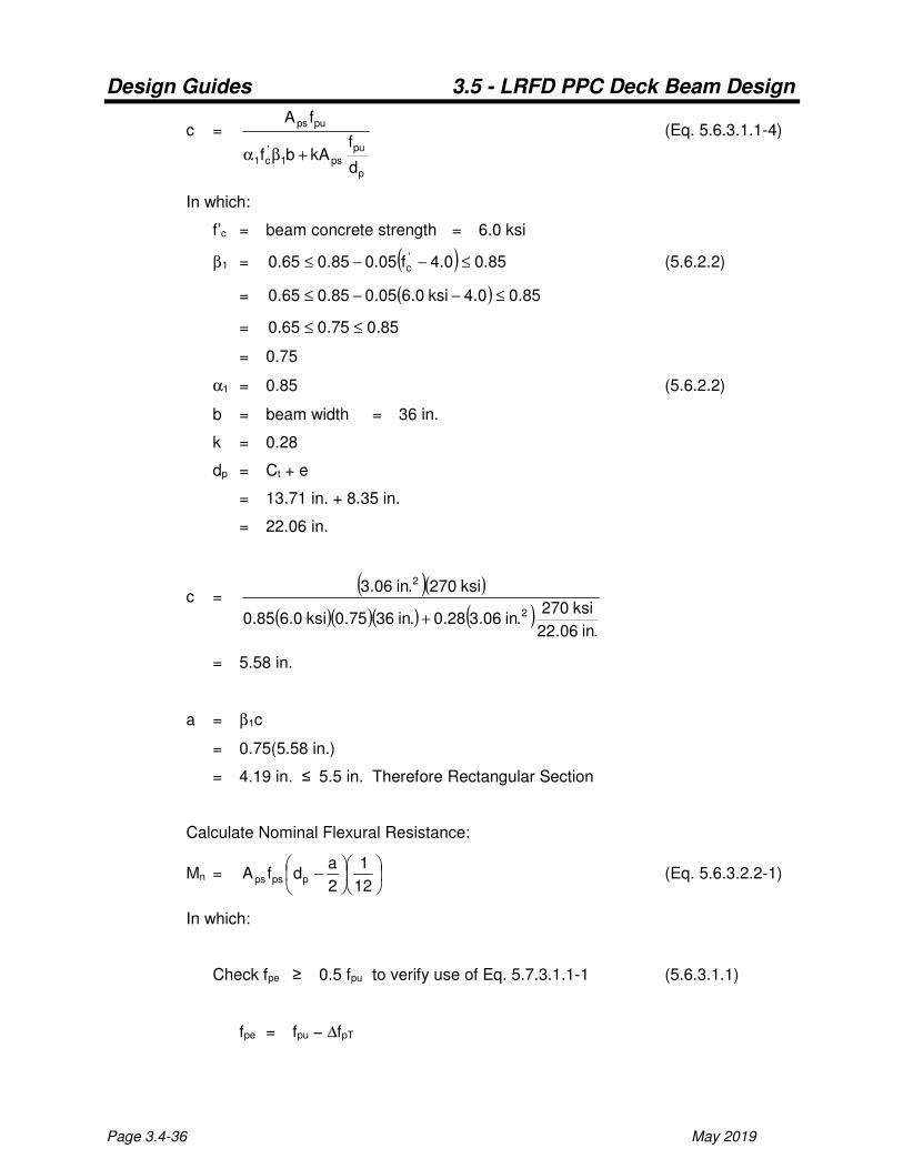
Calculate Compression Block Depth (assume rectangular):
Design Guides 3.5 - LRFD PPC Deck Beam Design
Page 3.4-36 May 2019
c =
p
pu
ps1'c1
pups
d
fkAbf
fA
+βα
(Eq. 5.6.3.1.1-4)
In which:
f’c = beam concrete strength = 6.0 ksi
β1 = ( ) 85.00.4f05.085.065.0 'c ≤−−≤ (5.6.2.2)
= ( ) 85.00.4ksi0.605.085.065.0 ≤−−≤
= 85.075.065.0 ≤≤
= 0.75
α1 = 0.85 (5.6.2.2)
b = beam width = 36 in.
k = 0.28
dp = Ct + e
= 13.71 in. + 8.35 in.
= 22.06 in.
c = ( )( )
( )( )( ) ( ).in06.22
ksi270.in06.328.0.in3675.0ksi0.685.0
ksi270.in06.3
2
2
+
= 5.58 in.
a = β1c
= 0.75(5.58 in.)
= 4.19 in. ≤ 5.5 in. Therefore Rectangular Section
Calculate Nominal Flexural Resistance:
Mn =
−
12
1
2
adfA ppsps (Eq. 5.6.3.2.2-1)
In which:
Check fpe ≥ 0.5 fpu to verify use of Eq. 5.7.3.1.1-1 (5.6.3.1.1)
fpe = fpu − ∆fpT
Design Guides 3.5 - LRFD PPC Deck Beam Design
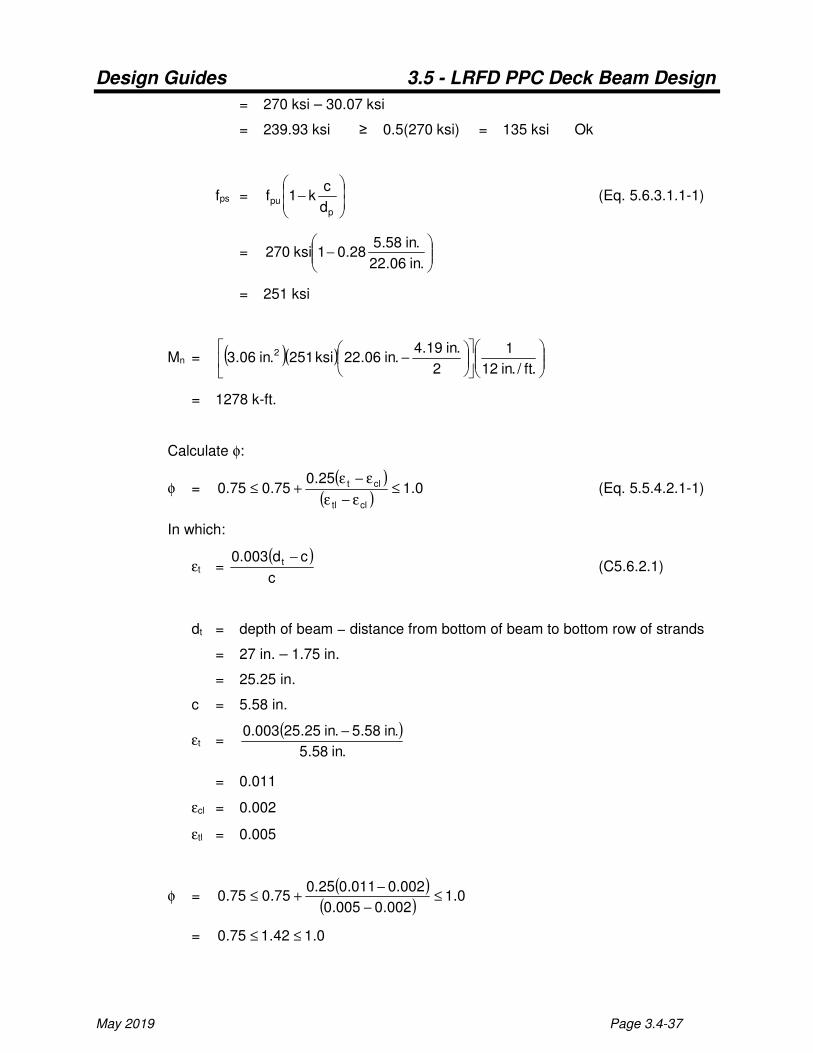
May 2019 Page 3.4-37
= 270 ksi – 30.07 ksi
= 239.93 ksi ≥ 0.5(270 ksi) = 135 ksi Ok
fps =
−
p
pud
ck1f (Eq. 5.6.3.1.1-1)
=
−
.in06.22
.in58.528.01ksi270
= 251 ksi
Mn = ( )( )
−
.ft/.in12
1
2
.in19.4.in06.22ksi251.in06.3 2
= 1278 k-ft.
Calculate φ:
φ = ( )
( )0.1
25.075.075.0
cltl
clt ≤ε−ε
ε−ε+≤ (Eq. 5.5.4.2.1-1)
In which:
εt = ( )c
cd003.0 t − (C5.6.2.1)
dt = depth of beam − distance from bottom of beam to bottom row of strands
= 27 in. – 1.75 in.
= 25.25 in.
c = 5.58 in.
εt = ( )
.in58.5
.in58.5.in25.25003.0 −
= 0.011
εcl = 0.002
εtl = 0.005
φ = ( )
( )0.1
002.0005.0
002.0011.025.075.075.0 ≤
−
−+≤
= 0.142.175.0 ≤≤
Design Guides 3.5 - LRFD PPC Deck Beam Design
Page 3.4-38 May 2019
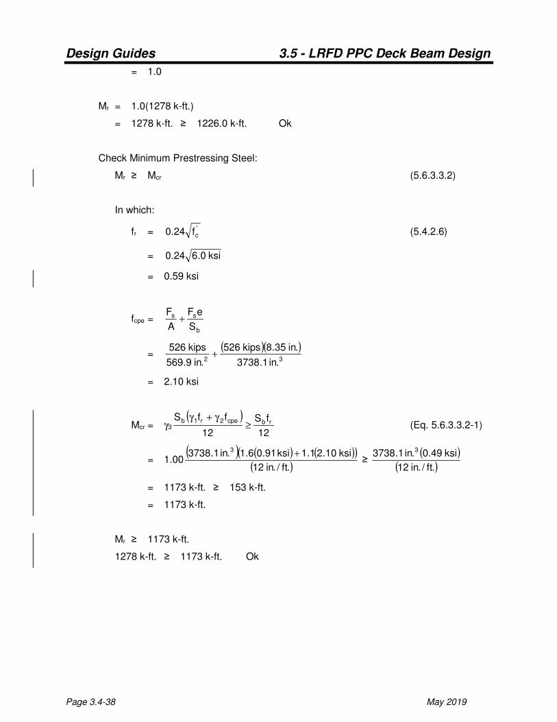
= 1.0
Mr = 1.0(1278 k-ft.)
= 1278 k-ft. ≥ 1226.0 k-ft. Ok
Check Minimum Prestressing Steel:
Mr ≥ Mcr (5.6.3.3.2)
In which:
fr = 'cf24.0 (5.4.2.6)
= ksi0.624.0
= 0.59 ksi
fcpe = b
ss
S
eF
A
F+
= ( )( )
32 .in1.3738
.in35.8kips526
.in9.569
kips526+
= 2.10 ksi
Mcr = γ3
( )12
fS
12
ffSrbcpe2r1b
≥γ+γ
(Eq. 5.6.3.3.2-1)
= 1.00( ) ( ) ( )( )
( ).ft/.in12
ksi10.21.1ksi91.06.1.in1.3738 3 + ≥
( )( ).ft/.in12
ksi49.0.in1.3738 3
= 1173 k-ft. ≥ 153 k-ft.
= 1173 k-ft.
Mr ≥ 1173 k-ft.
1278 k-ft. ≥ 1173 k-ft. Ok

Design Guides 3.5 - LRFD PPC Deck Beam Design
May 2019 Page 3.4-39
Calculate Camber and Deflection
Initial Resultant Camber
Camber = Dcp - Dcb
In which:
Dcp = ( )
( )80.1IE8
eL12F
ci
2
t
= ( ) ( )( )[ ] ( )
( )( )( )80.1
.in49697ksi42878
35.8.ft60.ft/.in12kips5924
2
= 2.71 in. up
Dcb = ( )
( ))85.1(
IE12384
L12w5
ci
4
net (net beam section)
= ( ) ( )( )[ ]( )( )( )
)85.1(.in49697ksi4287.ft/.in12384
.ft60.ft/.in12.ft/k594.054
4
= 1.50 in. down
Dcb = ( )
( ) ( )[ ] )85.1(L124L123IE24
12LP 2
tt
2
ci
ttT − (tie diaphragms)
= ( )( )
( )( )( ) ( ) ( ) ( )[ ]( )85.1.ft20.ft/.in124.ft60.ft/.in123
.in49697ksi428724
.ft/.in12.ft20kips9.0 2222
4−
= 0.10 in. down
Camber = 2.71 in.-1.50 in.-0.10 in.
= 1.11 in. up
Final Resultant Camber for Computing Bearing Seat Elevations
Camber = Dcp - Dcb - Dws
In which:
Dws = ( )
( ) IE12384
L12w5
c
4
ws

Design Guides 3.5 - LRFD PPC Deck Beam Design
Page 3.4-40 May 2019
= ( ) ( )( )[ ]( )( )( )4
4
.in49697ksi4696.ft/.in12384
ft60.ft/.in12.ft/k206.05
= 0.26 in. down
Camber = 2.71 in.-1.50 in.-0.10 in.-0.26 in.
= 0.85 in. up
0.85 in. is close enough to the 1 in. assumed camber therefore no reiteration is
necessary.
Downward Deflections Due to Overlay Weight for Adjusting Grade Elevations
@0.25 point = 0.7125Dws = 0.7125(0.26 in.) = 0.19 in.
@0.50 point = Dws = 0.26 in.
@0.75 point = 0.7125Dws = 0.7125(0.26 in.) = 0.19 in.
Design Guides 3.5 - LRFD PPC Deck Beam Design
May 2019 Page 3.4-41
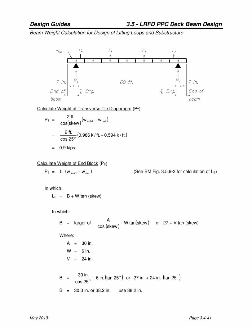
Beam Weight Calculation for Design of Lifting Loops and Substructure
Calculate Weight of Transverse Tie Diaphragm (PT)
PT = ( )
( )netsolid wwskewcos
.ft2−
= ( ).ft/k594.0.ft/k986.025cos
.ft2o
−
= 0.9 kips
Calculate Weight of End Block (PE)
PE = ( )netsolidE wwL − (See BM Fig. 3.5.9-3 for calculation of LE)
In which:
LE = B + W tan (skew)
In which:
B = larger of ( )
( )skewtanWskewcos
A− or 27 + V tan (skew)
Where:
A = 30 in.
W = 6 in.
V = 24 in.
B = ( )o
o25tan.in6
25cos
.in30− or 27 in. + 24 in. ( )o25tan
B = 30.3 in. or 38.2 in. use 38.2 in.

Design Guides 3.5 - LRFD PPC Deck Beam Design
Page 3.4-42 May 2019
LE = 38.2 in. + 6 in. ( )o25tan = 41.0 in.
PE = ( )( ).ft/k594.0.ft/k986.0.in12/.ft1.in0.41 −
= 1.3 kips
Total Beam Weight = ( ) ( ) ( )[ ]
++
k
.lb1000k9.02k3.12.ft17.61.ft/k594.0
= 40735 lbs. ∴Use 2 lifting loops at each end (See BM Fig. 3.5.9-4)
Rb = (0.5)(40735 lbs.)
.lbs1000
k1 = 20.4 k/beam


