
The information in this Manual is subject to change without notice and does not represent a commitment on the part of ALPHATRON MARINE B.V. Document : Manual ALPHAMINICOURSE Issue : 3.0 ALPHATRON MARINE B.V.
ALPHATRON MARINE B.V. Schaardijk 23 3063 NH ROTTERDAM The Netherlands Tel: +31 (0)10 – 453 4000 Fax: +31 (0)10 – 452 9214 P.O. Box 210003 3001 AA ROTTERDAM Web: www.alphatronmarine.com Mail: [email protected]
ALPHAMINICOURSE Gyro Compass
Installation and Operation MANUAL

Gyro Compass ALPHAMINICOURSE Issue 3.0 Page 2 of 68
ALPHAMINICOURSE GYRO COMPASS

Gyro Compass ALPHAMINICOURSE Issue 3.0 Page 3 of 68
ALPHAMINICOURSE GYRO COMPASS
CAUTIONARY NOTICES
Please note the following cautionary notices that apply throughout this Manual.
WARNING
The ALPHAMINICOURSE weights 12,5 kg. To avoid personal injury, take proper
precautions if the equipment is lifted or moved.
CAUTION!
The ALPHAMINICOURSE includes precision components and bearings. To avoid
damage of any part of the gyro compass/ handle all items with care.
During gyro compass transportation follow the requirements specified in chapter 7.
Retain the original transit cases so they can be used to transport the gyro compass
when necessary. One will void the warranty if improper packing during
transportation is used.
CAUTION!
It is forbidden to move the switched off gyro compass while rotor is still spinning!
Always allow a period of 5 minutes after you power-off the gyro compass for the
gyro rotor to stop spinning. Non-observance of this requirement may be the reason
of gyro compass damage.
CAUTION!
During operation gyro compass must remain level within ±45°. If its tilt is more than
45° in any direction, it will ‘topple’. Built-in test system will then power-off the gyro
rotor and show alarm conditions on the Control Unit. To restore normal operation,
level the gyro compass and then restart it.
Do not tilt gyro compass for more than 45° with the gyro rotor spinning or during the
gyro compass run-up. Note that the gyro rotor continues to spin for five minutes
after you power-off the system.
CAUTION!
If the gyro compass is placed in an enclosed space, make certain there is sufficient
ventilation and circulation of free air to allow effective cooling.
CAUTION!
Do not make any connections to the gyro compass with power on the supply cable.
CAUTION!
DO NOT modify this equipment in any way without obtaining a written permission
from ALPHATRON MARINE otherwise you will void the warranty.
CAUTION!
One will void warranty for operating the gyro compass in conditions different from
those specified in the chapter 5 and in IEC 60945-2002.
Gyro Compass ALPHAMINICOURSE Issue 3.0 Page 4 of 68
ALPHAMINICOURSE GYRO COMPASS
Gyro Compass ALPHAMINICOURSE Issue 3.0 Page 5 of 68
ALPHAMINICOURSE GYRO COMPASS
Contents 1 WARRANTY ......................................................................................................................................................... 7 2 INTRODUCTION ............................................................................................................................................ 7
2.1 Gyro compass Description .............................................................................................................................. 9 2.1.1 Main Unit of gyro compass ALPHAMINICOURSE .......................................................................................... 9 2.1.2 Control Unit ......................................................................................................................................... 10 2.1.3 Auxiliary Inputs .................................................................................................................................... 11 2.1.4 Heading Outputs .................................................................................................................................. 11
2.2. Principle of Operation .................................................................................................................................. 11 3. INSTALLATION .................................................................................................................................................. 13
3.1 Unpacking and Inspection ............................................................................................................................. 14 3.2. Installation and Connection.......................................................................................................................... 15
3.2.1 Selection of Place ................................................................................................................................. 15 3.2.2 Gyro compass Installation ..................................................................................................................... 16 3.2.3 Connection diagram Alphaminicourse ...................................................................................................... 20 3.2.4 Remote Control Unit ............................................................................................................................. 23 3.2.5 Setting of the Gyro compass Interfaces ................................................................................................... 25
3.3 Alignment .................................................................................................................................................. 29 3.4 Final Tests After Installation .......................................................................................................................... 29 3.5 Installation Drawings ................................................................................................................................... 30
4 PRESTARTING PROCEDURES AND OPERATION ...................................................................................................... 36 4.1 Control Features .......................................................................................................................................... 37 4.2 Power-on .............................................................................................................................................. 38 4.3 Operation ................................................................................................................................................... 39
4.3.1 Latitude correction ............................................................................................................................... 39 4.3.2 Speed correction .................................................................................................................................. 40 4.3.3 Operating mode (gyro compassing GC and directional gyro DG) ................................................................. 40
4.4 Error Modes ................................................................................................................................................ 41 4.4.1 Loss or corruption of GPS signal ............................................................................................................. 41 4.4.2 Loss of speed log .................................................................................................................................. 41 4.4.3 Gyro compass System Warnings and Failures ........................................................................................... 42
4.5 Operating Instructions ................................................................................................................................. 44 4.5.1 General ............................................................................................................................................... 44 4.5.2 Corrections for speed and latitude .......................................................................................................... 44 4.5.3 Operation in High Latitudes .................................................................................................................... 45 4.5.4 Operation on High Speed Crafts.............................................................................................................. 45
5 TECHNICAL DATA .............................................................................................................................................. 47 5.1 Specifications .............................................................................................................................................. 47
5.1.1 Power Requirements ............................................................................................................................. 47 5.1.2 Performance (definitions from ISO 8728) ................................................................................................. 47 5.1.3 Compensation ...................................................................................................................................... 47 5.1.4 Environment ........................................................................................................................................ 47 5.1.5 Signal Inputs ....................................................................................................................................... 48 5.1.6 Signal Outputs ..................................................................................................................................... 48 5.1.7 Dimensions and Weight ......................................................................................................................... 48 5.1.8 Input from the GPS-Receiver or Speed Log .............................................................................................. 49 5.1.9 Data Transmitters ................................................................................................................................ 49 5.1.10 Standards .......................................................................................................................................... 49
5.2 Data Formats ............................................................................................................................................. 50 5.2.1 IEC 61162 Serial Data Formats – General Information .............................................................................. 51 5.2.2 Inputs ................................................................................................................................................. 51 5.2.3 Outputs ............................................................................................................................................... 57 5.2.4 IEC 61162 Sentence with Checksum ...................................................................................................... 59 5.2.5 Other Output Formats ........................................................................................................................... 61
6 MAINTENANCE ................................................................................................................................................... 62 6.1 Gyro compass Alphaminicourse drift adjustment.............................................................................................. 62 6.2 Built-in Test Equipment ................................................................................................................................ 63 6.3 Fuse Replacement (3.15А 250V)................................................................................................................... 64 6.4 Alphaminicourse Diagrams ............................................................................................................................ 64
7 TRANSPORTATION .............................................................................................................................................. 65 7.1 Dual-use good ............................................................................................................................................. 65 7.2 Transport ................................................................................................................................................... 65
8 STORAGE ......................................................................................................................................................... 66 9 SERVICE ........................................................................................................................................................... 66 10 WARRANTY REGISTRATION FORM ...................................................................................................................... 67 11 GYRO SETTINGS REGISTRATION FORM ............................................................................................................... 68

Gyro Compass ALPHAMINICOURSE Issue 3.0 Page 6 of 68
ALPHAMINICOURSE GYRO COMPASS

Gyro Compass ALPHAMINICOURSE Issue 3.0 Page 7 of 68
ALPHAMINICOURSE GYRO COMPASS
1 WARRANTY
Following the installation of the Alphaminicourse either a copy of the Installation /
Commissioning report or the Warranty Registration Form is to be sent to Alphatron
Marine in Rotterdam ([email protected]) within two weeks. Carefully
note that the Installation / Commissioning report should cover at minimum the
information as requested on the Warranty Registration Form. The Warranty
Registration Form can be found in chapter 11. One should obey this procedure to
validate the warranty.
Following the installation of the Alphaminicourse a Gyro Settings Registration Form
is to be sent to Alphatron Marine in Rotterdam ([email protected])
together with the Warrant Registration Form. This information is requested for
presetting a reconditioned Alphaminicourse before it is replaced. The Gyro Settings
Registration Form can be found in chapter 12.
2 INTRODUCTION
The Gyro compass (GC) Alphaminicourse is designed for determination of the ship heading
relative to geographic meridian in the gyro compass (GC) mode and the trajectory deviation angle
in the directional gyro (DG) mode.
Specification of the Alphaminicourse makes it ideal for installation and operation on the vessels of
almost any size and various applications.
Among the features of the Alphaminicourse are:
Short settling time
Operation from 24V DC electrical supply
This Manual is an important part of the Alphaminicourse. It describes the gyro compass and
contains full installation and operating instructions. You should retain the Manual with the gyro
compass for use by personnel who will install and operate it.
Installation and operation of the Alphaminicourse are no complex tasks. However, it is necessary
to familiarize with the contents of this Manual before you start to install and use the gyro
compass. Time spent in identifying the test sequence now will ensure your gyro compass is
operational in the minimum time.
WARNINGS
Where appropriate, this Manual includes important safety information highlighted as
WARNING and CAUTION instructions. One should obey these instructions:
WARNING instructions alerts one to a potential risk of death or injury to users of the
gyro compass.
CAUTION instructions alerts one to a potential risk of gyro compass damage.
For one’s convenience, the section Introduction includes all the cautionary notices of
this Manual.
All measurements in this Manual conform to SI standard of units unless otherwise indicated.
Gyro Compass ALPHAMINICOURSE Issue 3.0 Page 8 of 68
ALPHAMINICOURSE GYRO COMPASS
Before gyro compass installation read sections 2 and 3:
--------------------------------------------------------------------------
Chapter 2 contains introductory notes and describes standard features.
Chapter 3 includes full instructions for safe and proper installation of gyro compass and its
connection to external equipment.
Before you use the gyro compass read sections 4 and 5:
----------------------------------------------------------------------------------------
Chapter 4 describes gyro compass operation.
Chapter 5 contains gyro compass specifications and description of data formats.
If you suspect a fault, read section 6:
-----------------------------------------------------------------------------
Chapter 6 contains information on gyro compass maintenance and diagrams.
Chapter 7 includes requirements for gyro compass transportation.
Chapter 8 includes requirements for gyro compass storage.
For service of the manual read section 9:
--------------------------------------------------------------------------
Chapter 9 contains information on the servicing of the gyro compass.
Gyro Compass ALPHAMINICOURSE Issue 3.0 Page 9 of 68
ALPHAMINICOURSE GYRO COMPASS
2.1 Gyro compass Description
The Alphaminicourse comprises the Main Unit with the Control Unit as an integrated part. The
Control Unit may be integral or remotely placed.
Figure 1.1 shows the general view of the gyro compass with the integral Control Unit. Due to the
physical principles of north-seeking gyro compass, achievable accuracy depends on the operating
latitude and the vessel dynamics. To decrease the heading error the Alphaminicourse uses
information supplied by external equipment, for example a GPS receiver and a speed log, to apply
latitude and speed corrections.
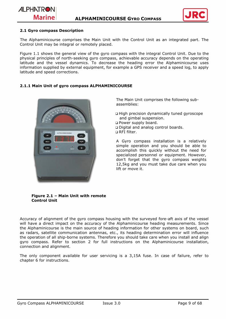
2.1.1 Main Unit of gyro compass ALPHAMINICOURSE
Figure 2.1 – Main Unit with remote
Control Unit
The Main Unit comprises the following sub-
assemblies:
High precision dynamically tuned gyroscope
and gimbal suspension.
Power supply board.
Digital and analog control boards.
RFI filter.
A Gyro compass installation is a relatively
simple operation and you should be able to
accomplish this quickly without the need for
specialized personnel or equipment. However,
don’t forget that the gyro compass weights
12,5kg and you must take due care when you
lift or move it.
Accuracy of alignment of the gyro compass housing with the surveyed fore-aft axis of the vessel
will have a direct impact on the accuracy of the Alphaminicourse heading measurements. Since
the Alphaminicourse is the main source of heading information for other systems on board, such
as radars, satellite communication antennas, etc., its heading determination error will influence
the operation of all ship-borne systems. Therefore you should take care when you install and align
gyro compass. Refer to section 2 for full instructions on the Alphaminicourse installation,
connection and alignment.
The only component available for user servicing is a 3,15A fuse. In case of failure, refer to
chapter 6 for instructions.

Gyro Compass ALPHAMINICOURSE Issue 3.0 Page 10 of 68
ALPHAMINICOURSE GYRO COMPASS
2.1.2 Control Unit
The Control Unit (CU) provides all the functions and indicators necessary to control and operate
the Alphaminicourse.
The four-character LED can show the following information:
Heading in degrees from 0.0 to 359.9
Latitude from 89S to 89N
Latitude source
Speed in knots from 0 to 90
Speed source
Alarms and status information
Separate LED indicators show presence of power and readiness of gyro compass for
operation
Refer to section 4 for instructions to operate the Alphaminicourse.
Gyro Compass ALPHAMINICOURSE Issue 3.0 Page 11 of 68
ALPHAMINICOURSE GYRO COMPASS
2.1.3 Auxiliary Inputs
Auxiliary inputs may be used for the Alphaminicourse speed and latitude correction.
Ideally, the Alphaminicourse should accept latitude and speed information from external sources
such as a GPS receiver or a speed log. However, you may input this information manually if
external sources are not available. The advantage of using GPS or a speed log to provide
correction signals is that they allow automatic corrections to be applied without operator
intervention.
Chapter 3 includes instructions to connect and configure the external sources of latitude and
speed information.
Chapter 4 includes instructions to set latitude and speed manually.
2.1.4 Heading Outputs
The Alphaminicourse is a self-contained precision navigation instrument capable of supplying
heading reference information simultaneously to a wide range of equipment located on board the
vessel. On a typical vessel heading information is used by:
Autopilot
Radars
Radio direction finder
Course plotter and course recorder
Satellite communication systems
Satellite television
To support this wide range of equipment, the Alphaminicourse can supply heading information
simultaneously through multiple channels using any of the common transmission formats.
Refer to Chapter 4 for a description of the available outputs and their data formats.
2.2. Principle of Operation
In the absence of external influences, a free-spinning gyroscope rotor will try to maintain a fixed
orientation in space. The Alphaminicourse exploits this property and uses earth gravitational
attraction and rotation to align the gyroscope spin axis with the meridian, i.e. in the true north
direction.

Gyro Compass ALPHAMINICOURSE Issue 3.0 Page 12 of 68
ALPHAMINICOURSE GYRO COMPASS
NOTES:
Gyro Compass ALPHAMINICOURSE Issue 3.0 Page 13 of 68
ALPHAMINICOURSE GYRO COMPASS
3. INSTALLATION
To obtain the best performance from the Alphaminicourse you must take care when you install
and connect it. This section includes all the information and instructions you will need to complete
these tasks.
You should read this section carefully and understand the important instructions that it contains
before you begin to install or connect the equipment.
3.1 Unpacking and Inspection page 14
----------------------------------------------------------------
Explains the inspection checks that you should perform after unpacking of the Alphaminicourse.
3.2. Installation and Connection page 15
----------------------------------------------------------------
Choose the suitable location to install the Alphaminicourse. Connect the system to an electrical
supply and to external equipment.
3.3 Alignment page 29
------------------------------------------------------------------
The care that you take as you align the Alphaminicourse with the fore-aft datum on the vessel will
have the direct influence upon its accuracy.

Gyro Compass ALPHAMINICOURSE Issue 3.0 Page 14 of 68
ALPHAMINICOURSE GYRO COMPASS
3.1 Unpacking and Inspection
WARNING
The ALPHAMINICOURSE weights 12,5kg. To avoid personal injury, take proper
precautions if the equipment is lifted or moved.
CAUTION!
The ALPHAMINICOURSE includes precision components and bearings. To avoid
damage of any part of the gyro compass/ handle all items with care.
During gyro compass transportation follow the requirements specified in chapter 7.
Retain the original transit cases so it can then be used to transport the gyro
compass when necessary. One will void the warranty if improper packing during
transportation is used.
CAUTION!
It is forbidden to move the switched off gyro compass while rotor is still spinning!
Always allow a period of 5 minutes after you power-off the gyro compass for the
gyro rotor to stop spinning. Non-observance of this requirement may be the reason
of gyro compass damage.
After you have received the gyro compass first of all check all items against the shipping
documents. Inspect the unit carefully to check for any damage that may have occurred during
transportation. If you find any damage, submit a claim to the carrier and immediately notify
ALPHATRON MARINE.
To avoid loss or damage of any component, store all sub-assemblies in the transit case until you
need to install them. Follow the storage requirements listed in the chapter 8.
If there is any components shortage in the shipment, notify ALPHATRON MARINE immediately.
You can find the contact details of ALPHATRON MARINE on the title page of this Manual.

Gyro Compass ALPHAMINICOURSE Issue 3.0 Page 15 of 68
ALPHAMINICOURSE GYRO COMPASS
3.2. Installation and Connection
3.2.1 Selection of Place
For proper installation of the Alphaminicourse carefully note the following requirements:
CAUTION!
During operation the gyro compass must remain level within ±45°. If its tilt is more
than 45° in any direction, it will ‘topple’. Safety routines in the gyro software will
then power-off the gyro rotor and show alarm conditions on the Control Unit. To
restore normal operation, level the gyro compass and then restart it.
Do not tilt the gyro compass for more than 45° with the gyro rotor spinning or
during the gyro compass run-up. Note that the gyro rotor continues to spin for five
minutes after you power-off the system.
CAUTION!
If you placed the gyro compass in an enclosed space, make certain there is
sufficient ventilation and circulation of free air to allow effective cooling.
Choose the place where the Alphaminicourse will be protected from damages.
Do not install or operate the Alphaminicourse where the ambient temperature could fall
below -15°С or rise above +55°С, or where rapid changes of temperature can occur.
Do not install the Alphaminicourse close to strong mechanical or electrical noise sources,
or in a location susceptible to vibration or shock.
Minimum allowed distance between the gyro compass housing and any standard magnetic
compass is 1.5 meters.
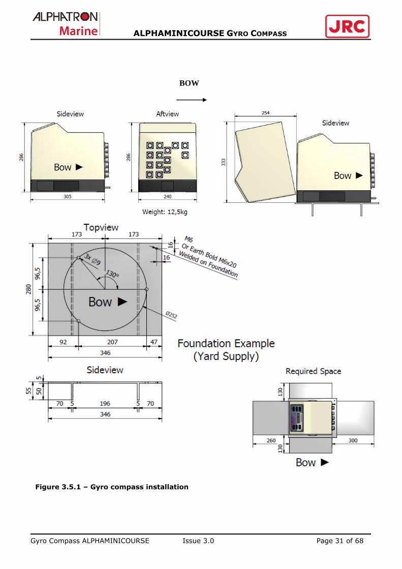
Choose the place so that there is a convenient access to the Alphaminicourse for
installation, connection and service. Required spacing is shown in the Figure 3.5.1.
Gyro Compass ALPHAMINICOURSE Issue 3.0 Page 16 of 68
ALPHAMINICOURSE GYRO COMPASS
3.2.2 Gyro compass Installation
The Alphaminicourse should be aligned so that its fore-aft axis is parallel to the fore-aft
datum of the vessel. Any misalignment between the compass housing and the vessel
will decrease the accuracy of heading measurements provided by the gyro compass.
To install the gyro compass you will need the following tools:
Hex male screwdriver with flat-to-flat dimension S2.5
Hex male screwdriver with flat-to-flat dimension S3.0
Screwdriver 5.5mm х 150mm
Screwdriver 3mm х 75mm
Two adjustable spanners with opening to at least 33mm
Suitable cables for the installation as indicated in the Table 3.1.
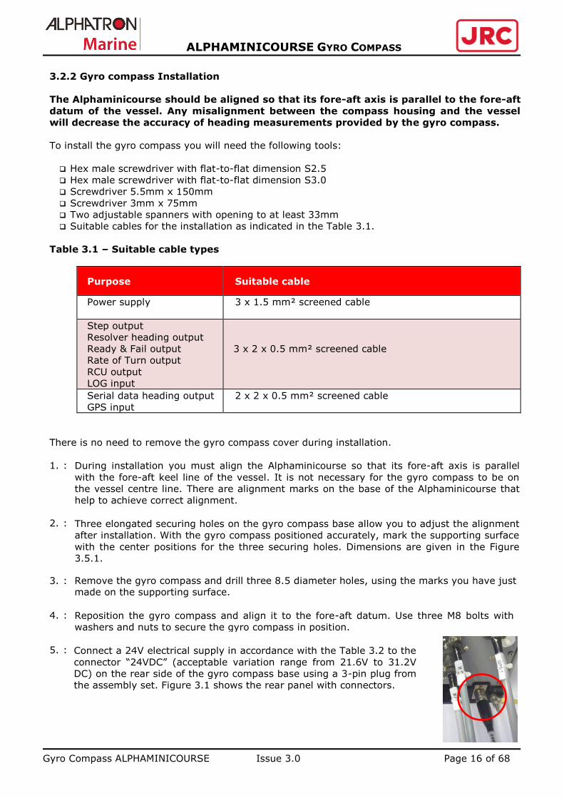
Table 3.1 – Suitable cable types
Purpose Suitable cable
Power supply 3 x 1.5 mm² screened cable
Step output
Resolver heading output
Ready & Fail output
Rate of Turn output
RCU output
LOG input
3 x 2 x 0.5 mm² screened cable
Serial data heading output
GPS input
2 x 2 x 0.5 mm² screened cable
There is no need to remove the gyro compass cover during installation.
1. :
2. :
3. :
4. :
5. :
During installation you must align the Alphaminicourse so that its fore-aft axis is parallel
with the fore-aft keel line of the vessel. It is not necessary for the gyro compass to be on
the vessel centre line. There are alignment marks on the base of the Alphaminicourse that
help to achieve correct alignment.
Three elongated securing holes on the gyro compass base allow you to adjust the alignment
after installation. With the gyro compass positioned accurately, mark the supporting surface
with the center positions for the three securing holes. Dimensions are given in the Figure
3.5.1.
Remove the gyro compass and drill three 8.5 diameter holes, using the marks you have just made on the supporting surface.
Reposition the gyro compass and align it to the fore-aft datum. Use three М8 bolts with
washers and nuts to secure the gyro compass in position.
Connect a 24V electrical supply in accordance with the Table 3.2 to the
connector “24VDC” (acceptable variation range from 21.6V to 31.2V
DC) on the rear side of the gyro compass base using a 3-pin plug from
the assembly set. Figure 3.1 shows the rear panel with connectors.
Gyro Compass ALPHAMINICOURSE Issue 3.0 Page 17 of 68
ALPHAMINICOURSE GYRO COMPASS
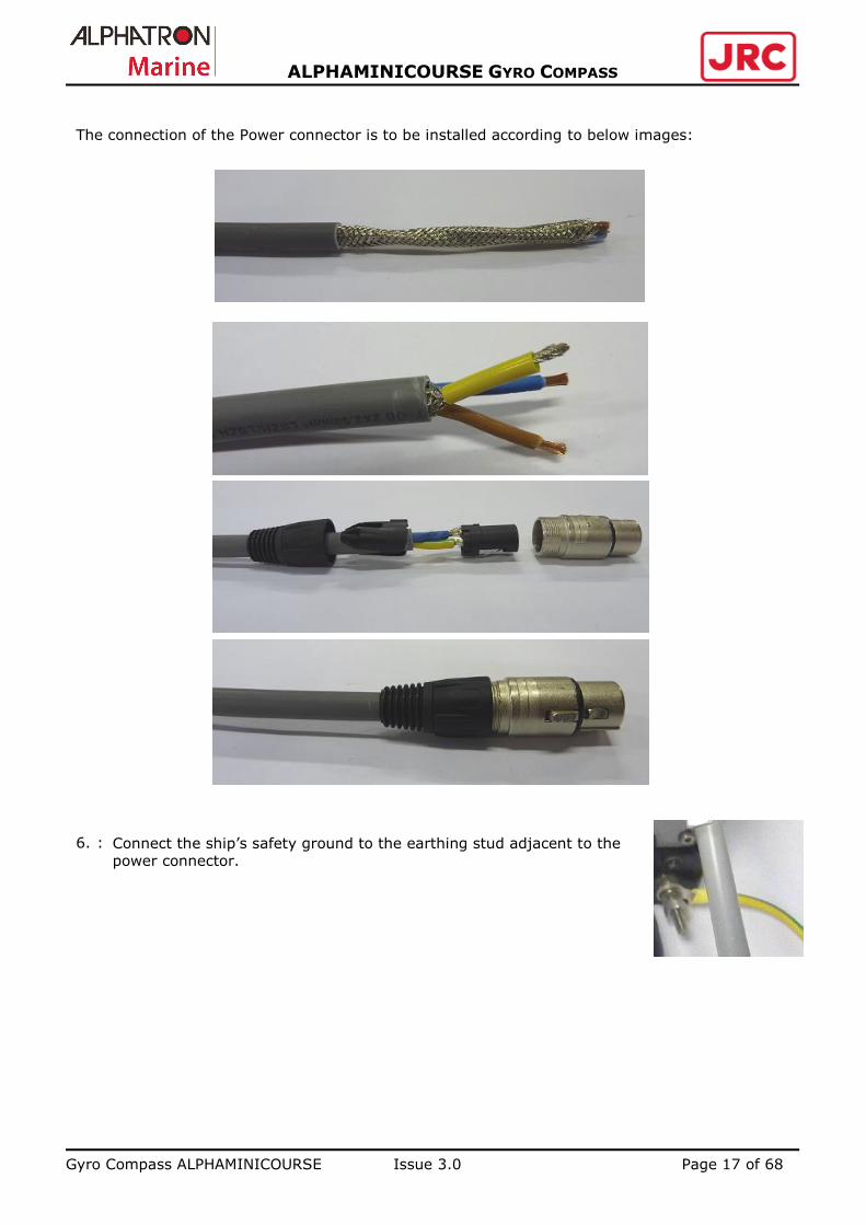
The connection of the Power connector is to be installed according to below images:
6. :
Connect the ship’s safety ground to the earthing stud adjacent to the power connector.
Gyro Compass ALPHAMINICOURSE Issue 3.0 Page 18 of 68
ALPHAMINICOURSE GYRO COMPASS
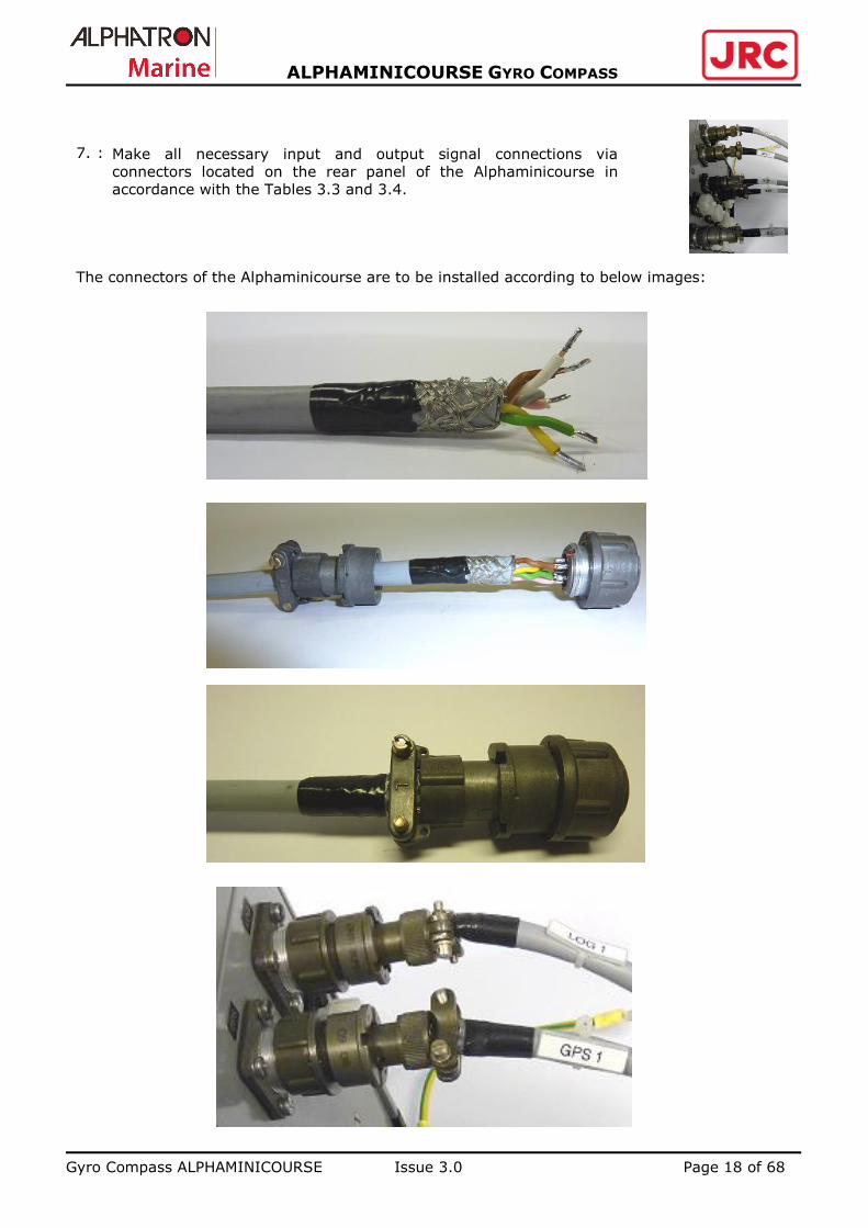
7. :
The connectors of the Alphaminicourse are to be installed according to below images:
Make all necessary input and output signal connections via
connectors located on the rear panel of the Alphaminicourse in
accordance with the Tables 3.3 and 3.4.

Gyro Compass ALPHAMINICOURSE Issue 3.0 Page 19 of 68
ALPHAMINICOURSE GYRO COMPASS
Figure 3.1 – Rear panel with connectors
24 VDC – 3 Pol. F.male with 10M cable (Item nr. G-002318)
X5, X6, X7, X8 – 4 Pol. male with 10M cable (Item nr. G-002319)
X13, X14 – 4 Pol. male with 10M cable (Item nr. G-002320)
RCU, X9, X10, X11, X15 – 7 Pol. male with 10M cable (Item nr. G-002322)
GPS – 7 Pol. F-male with 10M cable (Item nr. G-002323)
LOG, X12 – 7 Pol. F-male with 10M cable (Item nr. G-002324)

Gyro Compass ALPHAMINICOURSE Issue 3.0 Page 20 of 68
ALPHAMINICOURSE GYRO COMPASS
3.2.3 Connection diagram Alphaminicourse
-10v

Gyro Compass ALPHAMINICOURSE Issue 3.0 Page 21 of 68
ALPHAMINICOURSE GYRO COMPASS
Table 3.2 – Power supply input
Pin Description
24VDC/1 Cable shield
24VDC/2 +24V DC
24VDC/3 0V
Table 3.3 - Inputs
Signal
description Signal type Connector on the rear panel
GPS input IEC 61162 RS232
IEC 61162 RS422
GPS/6(+15 V) GPS/2(0 V)
GPS/1(A) GPS/2(V)
Log input IEC 61162 RS232
IEC 61162 RS422
LOG/3(+15 V) LOG/2 (0 V)
LOG/1(А) LOG/2(V)
Log input Pulses with amplitude from
5V to 10V
LOG/6(+15 V) LOG/7(0 V)
Table 3.4 – Outputs
Signal
description Signal type Output Connector on the rear panel
Heading
Channel A
IEC 61162-1/2 RS232 Х5/3(+15 V), Х5/4(0 V)
RS422 X5/1(A), X5/2(V)
RS422 X9/1(A), X9/2(V)
Heading
Channel B
IEC 61162-1/2 RS232 Х6/3(+15 V), Х6/4(0 V)
RS422 X6/1(A), X6/2(V)
RS422 X10/1(A), X10/2(V)
Heading
Channel C
IEC 61162-1/2 RS232 Х7/3(+15 V), Х7/4(0V)
RS422 X7/1(A), X7/2(V)
RS422 X11/1(A), X11/2(V)
RS422 X13/1(A), X13/2(V)
RS422 X14/1(A), X14/2(V)
Heading
Channel D
IEC 61162-1/2 RS232 Х8/3(+15 V), Х8/4(0 V)
RS422 X8/1(A), X8/2(V)
RS422 X13/3(A), X13/4(V)
RS422 X14/3(A), X14/4(V)
RS422 X15/1(A), X15/2(V)
Heading Step Х9/3(5 V)
X9/5(S1)
X9/6(S2)
X9/7(S3)
X9/4(0 V)
Failure FAIL CC Х12/5
FAIL NO X12/6
FAIL NC X12/7
Ready RDY CC Х12/1
RDY NC X12/2
RDY NO X12/3 Rate of Turn Analog ± 10 V Х10/4(+10V) Х10/5(-10V)
Х10/3(0V) Heading Resolver Х11/6(10V/400Hz) reference voltage
Х11/7(0V) reference voltage
Х11/4(2V/400Hz) sin
Х11/5(2V/400Hz) cos
Х11/3(0V)
Gyro Compass ALPHAMINICOURSE Issue 3.0 Page 22 of 68
ALPHAMINICOURSE GYRO COMPASS
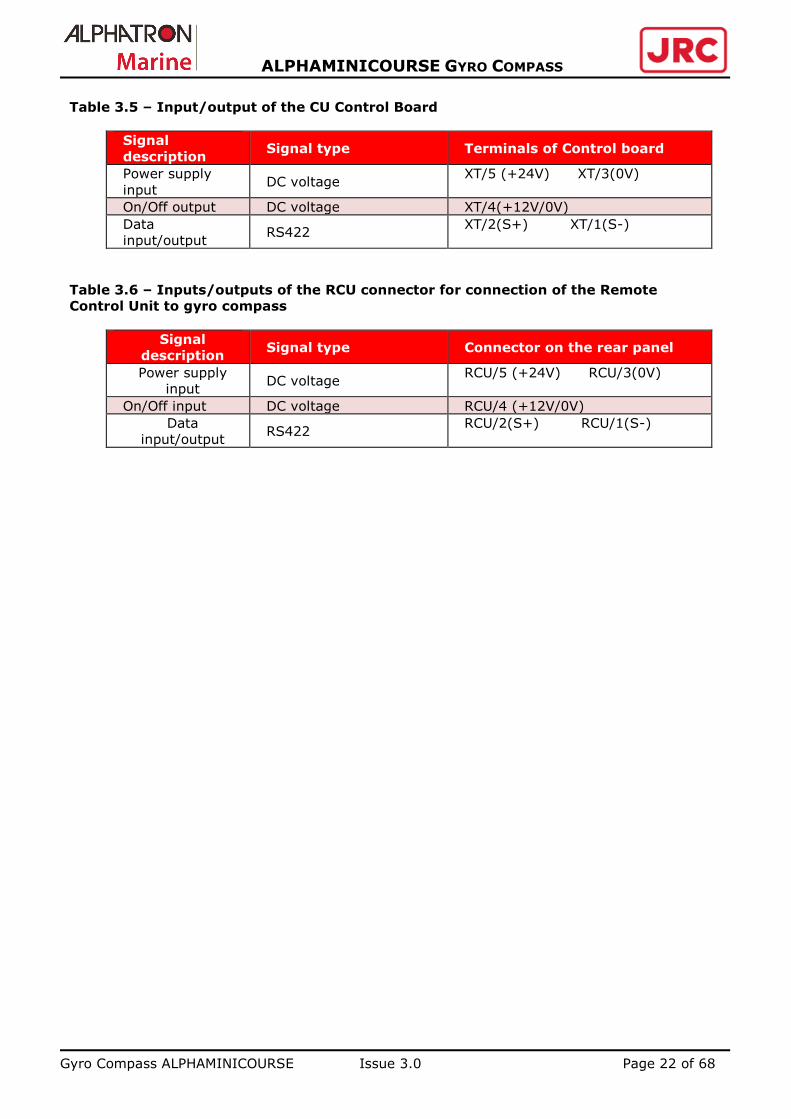
Table 3.5 – Input/output of the CU Control Board
Signal
description Signal type Terminals of Control board
Power supply
input DC voltage
XT/5 (+24V) XT/3(0V)
On/Off output DC voltage XT/4(+12V/0V)
Data
input/output RS422
XT/2(S+) XT/1(S-)
Table 3.6 – Inputs/outputs of the RCU connector for connection of the Remote
Control Unit to gyro compass
Signal
description Signal type Connector on the rear panel
Power supply
input DC voltage
RCU/5 (+24V) RCU/3(0V)
On/Off input DC voltage RCU/4 (+12V/0V)
Data
input/output RS422
RCU/2(S+) RCU/1(S-)

Gyro Compass ALPHAMINICOURSE Issue 3.0 Page 23 of 68
ALPHAMINICOURSE GYRO COMPASS
3.2.4 Remote Control Unit
There may be applications where you prefer to install the Control Unit at some distance from the
gyro compass. For this purpose you may use Remote Control Unit. Housing of RCU into which the
CU from the Main Unit is mounted is provided as a mounting kit.
The mounting kit includes the following items:
RCU housing
Blanking plate for the Main Unit housing
Fastening parts for mounting
2m 3x2x0,5mm2 cable (see drawing)
There is no need to remove the gyro compass cover to install RCU externally:
1. Release and remove the four М3 screws at the corners of the CU that secure it to the housing
of the Main Unit.
2. Lift the CU away from the Main Unit.
3. Disconnect the CU cable from the Y-cable on the analog PCB. Instead connect the second cable
that is located nearby. If there is no Y-cable inside and purchased a brand new gyro please
contact Alphatron: ([email protected]).
4. Disconnect the cable from the CU, release the terminal screws.
5. You may place the RCU on the table.
Select a location for the RCU:
The mounting surface can be vertical or horizontal according to requirements.
Avoid installing the RCU where it might be exposed to shock or vibration.
Choose a location for the RCU that allows a clear view of the display in all conditions.
6. Take the cable for interconnection of the RCU to the Main Unit. Route the cable through the
cable gland on the CU housing.
The cable, run between the gyro compass and the RCU, must not exceed 100 meters.
7. In accordance with Tables 3.5, and 3.6 connect the cable to the terminals of the CU and to the
connector RCU on the rear panel of the Main Unit.
8. Fit the CU into the housing and screw four M3 screws at the corners of the CU.
9. Fit the blanking plate to fill the gap left in the cover of the Main Unit after the removal of the
CU.
Gyro Compass ALPHAMINICOURSE Issue 3.0 Page 24 of 68
ALPHAMINICOURSE GYRO COMPASS
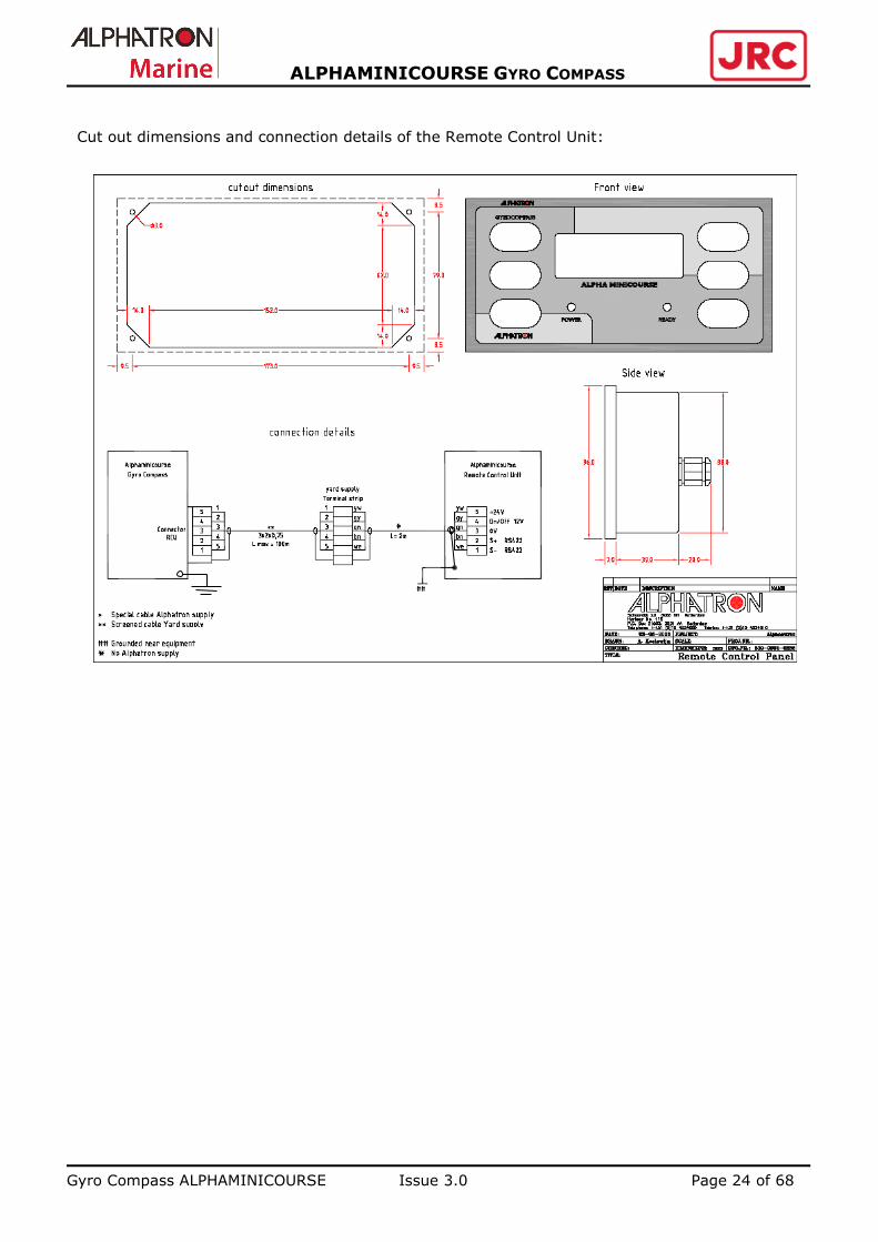
Cut out dimensions and connection details of the Remote Control Unit:
[Geef een citaat
uit het
document of de
samenvatting
van een
interessant punt
op. Het
tekstvak kan
overal in het
document
worden
neergezet. Ga
naar het tabblad
Hulpmiddelen
voor
tekstvakken als
u de opmaak
van het
tekstvak voor
het
blikvangercitaat
wilt wijzigen.]

Gyro Compass ALPHAMINICOURSE Issue 3.0 Page 25 of 68
ALPHAMINICOURSE GYRO COMPASS
3.2.5 Setting of the Gyro compass Interfaces
The DIP-switch is used for simultaneous setup of all digital channels.
1. DIP-switches are located on the Controller board of the Control Unit. To lift off the CU it’s no
need to remove the gyro compass cover, simply release and remove the four fixing screws of
the CU.
2. Carefully set the DIP SWITCHES in accordance with your particular requirements using the
Table 3.7. Don’t change the settings of other switches inside the gyro compass.
3. Refit the CU to its place.
Back side of Remote Control Unit
Dipswitches

Gyro Compass ALPHAMINICOURSE Issue 3.0 Page 26 of 68
ALPHAMINICOURSE GYRO COMPASS
Table 3.7 – Setting of the DIP-switches
DIP-switch
Number and
Setting Function
1 2
Off
On
Off
On
Off
Off
On
On
Baud rate
4800 baud (digital output RS232 and RS422)*
9600 baud (digital output RS232 and RS422)
19200 baud (digital output RS232 and RS422)
38400 baud (digital output RS232 and RS422)
3
Off
On
Heading decimal place
One decimal place (digital heading output)*
Two decimal places (digital heading output)
4
Off
On
Checksum
No checksum (digital output RS232 and RS422)*
Checksum transmitted (digital output RS232 and RS422)
5
Off
On
Off
On
6
Off
Off
On
On
Output sentences
THS (digital output RS232 and RS422) *
THS and ROT (digital output RS232 and RS422)
HDT and VHW (digital output RS232 and RS422)
HDT and ROT (digital output RS232 and RS422)
7
Off
On
Off
On
8
Off
Off
On
On
Speed log input type
Log NMEA serial *
100 pulses per nautical mile
200 pulses per nautical mile
400 pulses for nautical mile
Factory default settings appear in bold and are marked by asterisk in this table.
3.2.5.1 Setting of the digital interface on the Control Unit
Each digital channel may have individual local settings (that are different from the global settings
of DIP-switches on the Control Unit).
To enter the mode of channel tuning press and hold the button «SPEED» and then switch on the
gyro compass. The display will indicate:
O U T x
where x – number of a channel (beginning from 1st up to 4th: A, B, C, D consequently).
With arrow buttons select the required channel or EXIT:
if EXIT is selected, press the button “LAT” to return to the operation mode with retaining of
all adjustments in non-volatile memory of the unit;
if you would like to make settings in this or that channel, each time you press the “LAT”
button one of the following channel parameters is selected successively:
B x x.x – transmission rate (Bauds)
x x.H Z – data rate (Hz)
P x x x – accuracy of heading (Precision)
C S x – availability of Checksum (CheckSum)
S.x x x – set of sentences (Sentences)

Gyro Compass ALPHAMINICOURSE Issue 3.0 Page 27 of 68
ALPHAMINICOURSE GYRO COMPASS
When the parameters are selected the unit returns to the tuning mode, i.e. the display will
indicate OUT x. You may repeat the same procedure for other channels or finish the setting. The
Parameter marked by D (excluding data rate parameter) means that it is set in accordance with
Table 2.7. To change the value of the parameter select the required value with arrow buttons and
then press the button “LAT” to go to the next parameter:
B D – Global data transmission rate (factory setting)
B 4.8 – 4800 bit/s (factory setting)
B 9.6 – 9600 bit/s
B 1 9.2 – 19200 bit/s
В 38.4 – 38400 bit/s
1.H Z – 1 time a second
1 0.H Z – 10 times a second (factory setting)
2 0.H Z – 20 times a second
5 0.H Z – 50 times a second
P D – Global heading accuracy (factory setting)
P 0.1 – One decimal place
P 0.0 1 – Two decimal places
C S D – Global checksum (factory setting)
C S 0 – Checksum is not transmitted
C S 1 – Checksum is transmitted
S. D – Global set of sentences (factory setting)
S.H D T – HDT
S.H + R – HDT + ROT
S.H + V – HDT + VHW
S.V + R – VHW+ ROT
S.T H S – THS
S.T + R – THS + ROT
S.A L L – «All Data»
In the mode “All Data” HDT, ROT and additional sentences with coordinates and speed of
movement are transmitted. Sentence package is transmitted once a second despite of
independent of transmission channel settings. Detailed description is given in the subsection
5.2.3.
3.2.5.2 Setting of the analog interface and Backward Running Mode
DIP-switches on the Digital board are used to set the scale of the analog rate of turn and the ROT
limit for the step signal.
1. DIP-switches are located on the Digital pcb. Without removing the gyro compass cover
unscrew and remove 4 securing screws to take the Control Unit out.
2. Set DIP-switches on the Digital pcb carefully for specific requirements of your installation.
3. The Scale of the analog rate of turn is selected by setting of three DIP-switches in accordance
with the Table 3.8.
4. The ROT limit for the step signal is selected by setting of two DIP-switches on the Digital pcb in
accordance with the Table 3.9.
5. Backward running mode is selected by one of the DIP-switches in accordance with Table 3.10
6. Refit the Control Unit to its place.
Gyro Compass ALPHAMINICOURSE Issue 3.0 Page 28 of 68
ALPHAMINICOURSE GYRO COMPASS
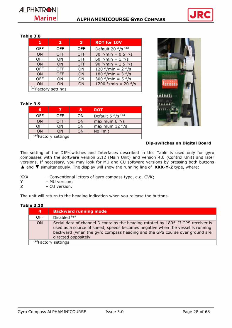
Table 3.8
1 2 3 ROT for 10V
OFF OFF OFF Default 20 °/s (*)
ON OFF OFF 30 °/min = 0,5 °/s
OFF ON OFF 60 °/min = 1 °/s
ON ON OFF 90 °/min = 1,5 °/s
OFF OFF ON 120 °/min = 2 °/s
ON OFF ON 180 °/min = 3 °/s
OFF ON ON 300 °/min = 5 °/s
ON ON ON 1200 °/min = 20 °/s (*)Factory settings
Table 3.9
6 7 8 ROT
OFF OFF ON Default 6 °/s (*)
ON OFF ON maximum 6 °/s
OFF ON ON maximum 12 °/s
ON ON ON No limit (*)Factory settings
Dip-switches on Digital Board
The setting of the DIP-switches and Interfaces described in this Table is used only for gyro
compasses with the software version 2.12 (Main Unit) and version 4.0 (Control Unit) and later
versions. If necessary, you may look for MU and CU software versions by pressing both buttons
▲ and ▼ simultaneously. The display will show the running line of XXX-Y-Z type, where:
ХХХ – Conventional letters of gyro compass type, e.g. GVK;
Y – MU version;
Z – CU version.
The unit will return to the heading indication when you release the buttons.
Table 3.10
4 Backward running mode
OFF Disabled (*)
ON Serial data of channel D contains the heading rotated by 180°. If GPS receiver is
used as a source of speed, speeds becomes negative when the vessel is running
backward (when the gyro compass heading and the GPS course over ground are
directed oppositely (*)Factory settings

Gyro Compass ALPHAMINICOURSE Issue 3.0 Page 29 of 68
ALPHAMINICOURSE GYRO COMPASS
3.3 Alignment
It is very important to align the gyro compass to the fore-aft datum on the vessel accurately. Any
misalignment will appear directly as a fixed error in heading measurements. Because
measurements from the Alphaminicourse are used by diverse systems around the vessel, any
misalignment between the gyro compass and the fore-aft datum might have a significant impact
on these systems operation.
There are several methods of gyro compass alignment to the vessel fore-aft datum:
Align the gyro compass to the fore-aft axis using a known reference line, such as surveyed
bulkhead or frame member. The marks on the gyro compass base plate are precision
indicators of the gyro compass alignment orientation.
To provide perfect speed correction the gyro compass panel with connectors shall be
oriented to the vessel bow.
Use the direction finder to align the gyro compass precisely with the fore-aft datum on the
vessel.
Remove any residual misalignment by making miniscule adjustments to the gyro compass
mounting plate. When you have achieved perfect alignment, tighten the securing bolts fully to
lock the gyro compass in position.
3.4 Final Tests After Installation
After you have installed the gyro compass and connected power supplies to it, perform the
following tests:
1. Power-on the gyro compass by following the instructions in sub-section 4.2. Wait for three
hours before you perform the following tests.
2. Check the vessel heading against the known reference mark on a chart. Typically this could be
the alongside position of the fitting-out dock. Alternatively, accurately survey an object at least
five kilometers ahead of the vessel using the fore-aft line as a datum.
3. Check the displayed gyro compass heading at definite intervals to make certain it is consistent
with the surveyed vessel heading.
4. If there is an error larger than ± 0.5°, re-check the vessel fore-aft datum to confirm that it is
correct.
5. Check that all repeaters are accurately aligned with the gyro compass heading and make
certain they maintain their alignment at all times while the gyro compass is operating.

Gyro Compass ALPHAMINICOURSE Issue 3.0 Page 30 of 68
ALPHAMINICOURSE GYRO COMPASS
3.5 Installation Drawings
Figure 3.5.1 – Gyro compass installation
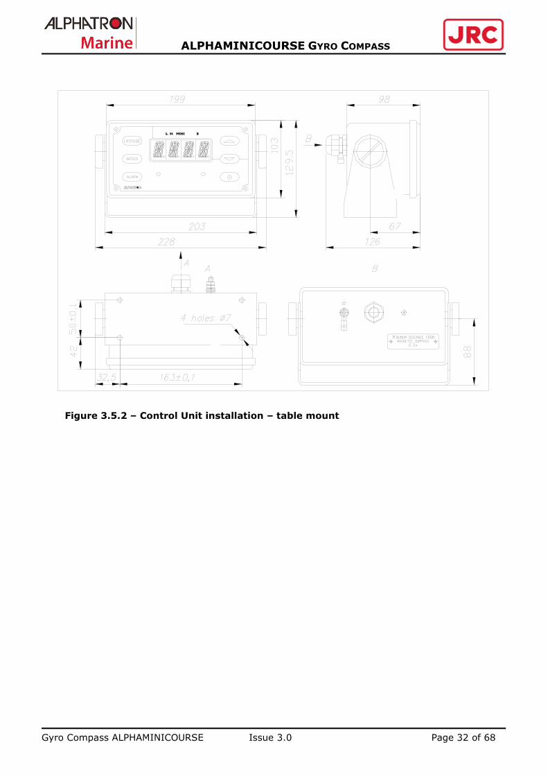
Figure 3.5.2 – Control Unit installation – table mount
Figure 3.5.3 – Installation Alphaminicourse Steering repeater Alphacourse G
Figure 3.5.4 – Installation Alphaminicourse Bearing repeater Alphacourse B
Gyro Compass ALPHAMINICOURSE Issue 3.0 Page 31 of 68
ALPHAMINICOURSE GYRO COMPASS
Figure 3.5.1 – Gyro compass installation
BOW
Gyro Compass ALPHAMINICOURSE Issue 3.0 Page 32 of 68
ALPHAMINICOURSE GYRO COMPASS
Figure 3.5.2 – Control Unit installation – table mount

Gyro Compass ALPHAMINICOURSE Issue 3.0 Page 33 of 68
ALPHAMINICOURSE GYRO COMPASS
Figure 3.5.3 – Installation drawing Alphaminicourse Steering repeater Alphacourse G
The Alphacourse G is the steering repeater in the Alphaminicourse gyro system. The installation
drawing is as follows:
Gyro Compass ALPHAMINICOURSE Issue 3.0 Page 34 of 68
ALPHAMINICOURSE GYRO COMPASS
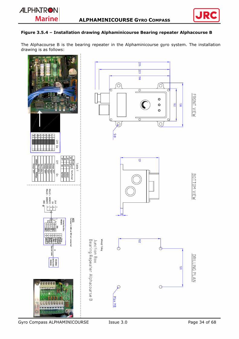
Figure 3.5.4 – Installation drawing Alphaminicourse Bearing repeater Alphacourse B
The Alphacourse B is the bearing repeater in the Alphaminicourse gyro system. The installation
drawing is as follows:

Gyro Compass ALPHAMINICOURSE Issue 3.0 Page 35 of 68
ALPHAMINICOURSE GYRO COMPASS
NOTES:
Gyro Compass ALPHAMINICOURSE Issue 3.0 Page 36 of 68
ALPHAMINICOURSE GYRO COMPASS
4 PRESTARTING PROCEDURES AND OPERATION
This section explains how to power-on and operate the Alphaminicourse after installation. Data
formats relevant to the system are given in section 4.
4.1 Control Features page 37
-----------------------------------------------------------------
The CU provides all the controls you will need to operate the Alphaminicourse as well as 4-
character display panel that shows the heading and any alarm messages and error codes.
4.2 Power-on page 38
------------------------------------------------------------------
Explains how to power-on the Alphaminicourse after installation and describes the initialization
sequence.
4.3 Operation page 39
------------------------------------------------------------------
Explains how to select the latitude and speed correction sources, and how to set the latitude and
speed manually if necessary.
4.4 Error Modes page 41
------------------------------------------------------------------
Identifies the system error modes. Use these indicators to identify a possible fault condition.
4.5 Operating instructions page 44
------------------------------------------------------------------
Includes general advice for operating the Alphaminicourse on a vessel.
Gyro Compass ALPHAMINICOURSE Issue 3.0 Page 37 of 68
ALPHAMINICOURSE GYRO COMPASS
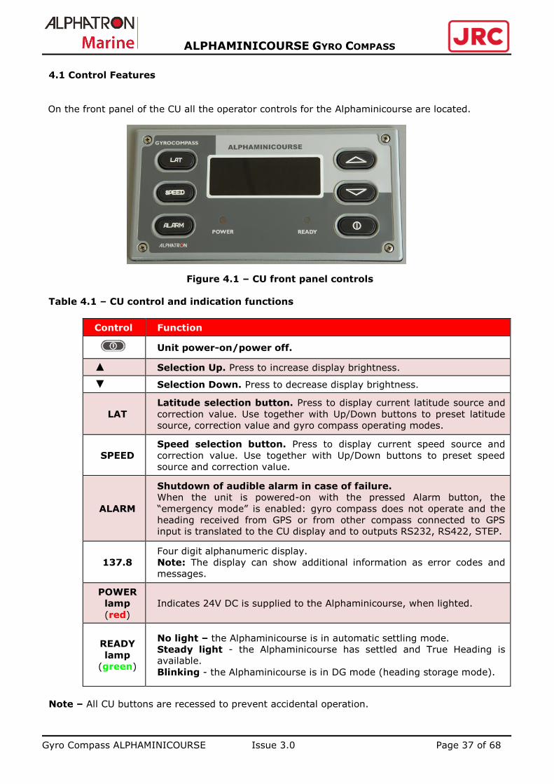
4.1 Control Features
On the front panel of the CU all the operator controls for the Alphaminicourse are located.
Figure 4.1 – CU front panel controls
Table 4.1 – CU control and indication functions
Control Function
Unit power-on/power off.
▲ Selection Up. Press to increase display brightness.
▼ Selection Down. Press to decrease display brightness.
LAT
Latitude selection button. Press to display current latitude source and
correction value. Use together with Up/Down buttons to preset latitude
source, correction value and gyro compass operating modes.
SPEED
Speed selection button. Press to display current speed source and
correction value. Use together with Up/Down buttons to preset speed
source and correction value.
ALARM
Shutdown of audible alarm in case of failure.
When the unit is powered-on with the pressed Alarm button, the
“emergency mode” is enabled: gyro compass does not operate and the
heading received from GPS or from other compass connected to GPS
input is translated to the CU display and to outputs RS232, RS422, STEP.
137.8
Four digit alphanumeric display.
Note: The display can show additional information as error codes and
messages.
POWER
lamp
(red)
Indicates 24V DC is supplied to the Alphaminicourse, when lighted.
READY
lamp
(green)
No light – the Alphaminicourse is in automatic settling mode.
Steady light - the Alphaminicourse has settled and True Heading is
available.
Blinking - the Alphaminicourse is in DG mode (heading storage mode).
Note – All CU buttons are recessed to prevent accidental operation.

Gyro Compass ALPHAMINICOURSE Issue 3.0 Page 38 of 68
ALPHAMINICOURSE GYRO COMPASS
Table 4.2 – CU display formats
Format Function
Heading
012.3
Heading Only
Speed
01
G01
L01
L
(by pressing the Speed button)
Speed value with manually selected speed source
Speed value with GPS selected speed source
Speed value with LOG selected speed source with NMEA
output
Speed value with LOG selected speed source with pulsed
output
Latitude
52N
52S
G52N
(by pressing Latitude button)
Latitude value in the Northern Hemisphere with manually
selected latitude source
Latitude value in the Southern Hemisphere with manually
selected latitude source
Latitude value with GPS selected latitude source
GC operating modes
GPS
LOG
GC
DG
Operation of the GC with GPS receiver (pp.4.3.1 and 4.3.2)
Operation of the GC with log (p.4.3.2)
Gyro compass operating mode (p.4.3.3)
Heading storage mode (Directional Gyro) (p.4.3.3)
4.2 Power-on
The gyro compass starting cycle is fully automatic. To initialize the gyro compass operation you
shall do the following:
1. Check that there is a nominal 24V DC electrical supply available to the gyro compass.
The acceptable supply range is 21.6 VDC to 31.2 VDC. To ensure continuous operation, the
power supply for this unit should have 100W power rating.
2. To start the Alphaminicourse press the power switch on the CU
3. The red «POWER» lamp on the CU shall illuminate that indicates that the Main Unit of the gyro
compass is receiving power.
4. The CU will enable the audible alarm for about 1 second. The display will show the current gyro
compass dial heading and the «READY» lamp will not light until the gyro compass has settled.
If there is no heading indication on the display and alarm is enabled, it means that the unit
doesn’t pass testing or there is no connection with the CU.
5. Set the source of latitude information on the CU by following the instructions of p.4.3.1.
6. Set the source of speed information on CU by following the instructions of p. 4.3.2, if GPS is
not selected as data source. 7. Use buttons ▲, ▼ to adjust the CU illumination level to a comfortable setting.
8. Wait for the gyro compass to settle. This will occur automatically and will take from 30 minutes
to 2 hours depending on initial heading offset and sea conditions. The Alphaminicourse signifies
its settled condition by illuminating the green lamp «READY».
9. If necessary, you can view the software versions of the Main Unit and the Control Unit by
simultaneous pressing of buttons ▲and ▼. The display will show the running line of XXX-Y-Z
type, where:
XХХ – conventional letters of gyro compass type, e.g. GVK;
Y – MU version;
Z – CU version.
The unit will return to the heading indication when you release the buttons.

Gyro Compass ALPHAMINICOURSE Issue 3.0 Page 39 of 68
ALPHAMINICOURSE GYRO COMPASS
4.3 Operation
The Alphaminicourse will settle automatically after power-on. To perform the specified accuracy,
the system requires latitude and speed correction, applied manually or from external sources.
Ideally, the Alphaminicourse should accept latitude and speed information from external sources
such as GPS or a speed log, which allows the system to apply corrections automatically.
4.3.1 Latitude correction
1. Press and hold the Latitude selection button.
2. Use buttons ▲ and ▼ to set the local latitude manually. The display will show the latitude in one
degree increments in the range 89°N to 89°S, for example, 70N.
3. To select automatic latitude and speed compensation from GPS receiver, use the buttons ▲ and
▼ to scroll beyond 89°N or 89°S until the display shows GPS.
To select automatic compensation of latitude from GPS receiver and speed from log paragraphs
4.3.1.3, 4.3.2.1 and 4.3.2.3 of this manual shall be followed consequently.
If there is no valid input from GPS receiver, the display will indicate the alarm NO+GPS
in 10 seconds.
If the input is not recognized or is invalid during 10 seconds, the display will indicate
the alarm ????+GPS (input format is not recognized) or ERR+GPS (input checksum is invalid).
4. Release both buttons to set the speed to the displayed value or to set the gyro compass to use
GPS as the source of automatic latitude and speed correction. The display will then return to
normal heading indication.
Note: The latest set latitude and operating mode are preserved in the gyro compass
software and are restored after switching on.
If operating latitude is selected manually, remember to change the setting when
necessary.
In medium latitudes, a 10° error in setting the operating latitude will result in compass
error of approximately 0.3°.
Gyro Compass ALPHAMINICOURSE Issue 3.0 Page 40 of 68
ALPHAMINICOURSE GYRO COMPASS
4.3.2 Speed correction
1. Press and hold Speed selection button.
2. Use buttons ▲ and ▼ to set the speed manually in the range from 0 to 90 knots.
3. To select automatic speed compensation from log, use the buttons ▲ and ▼ to scroll beyond
90 knots until the display shows LOG
If there is no NMEA signal from log, the display will indicate the alarm NO+LOG in 10
seconds.
If input is not recognized or invalid within 10 seconds, the display will indicate the
alarm ????+ LOG (input format is not recognized), ERR+LOG (input checksum is invalid).
4. Release both buttons to set the speed to the displayed value or to set the gyro compass to use
log as the source of automatic speed correction. The display will then return to the normal
heading indication.
Note: The latest set speed and operating mode are preserved in the gyro compass
software and are restored after switching on.
If the vessel speed is selected manually, remember to set the average vessel speed and
to change the setting when necessary. On completion of the voyage return the setting
to zero. For a vessel steaming along the meridian, a 5-knot error in speed setting will
generate an error of approximately 0.5°.
4.3.3 Operating mode (gyro compassing GC and directional gyro DG)
5. Press and hold the Latitude selection button.
6. Use the buttons ▲ and ▼ to scroll beyond the range 89N to 89S and GPS until the display
shows GC and then DG. In the GC mode the gyro compass will be a north-seeking and in the
DG mode the gyro compass is a direction saving instrument In this mode you may use the
Alphaminicourse as the heading indicator up to the Pole. If the gyro compass has settled on
north immediately prior to entering into the DG mode, it will continue to provide a proper
indication of the northerly direction for some period, but will not continue to seek north. The
validity period depends entirely on the gyroscope drift characteristics.
7. Release both buttons to set the gyro compass operating mode. The display will indicate the
selected operating mode for several seconds and will then return to the normal heading
display. When the DG mode is selected the green «READY» indicator on the CU will start to
blink.
Note:
The latest set operating mode is preserved in the gyro compass software and is restored
after switching on. Gyro compass will not seek north while operating in the DG mode.

Gyro Compass ALPHAMINICOURSE Issue 3.0 Page 41 of 68
ALPHAMINICOURSE GYRO COMPASS
4.4 Error Modes
The Alphaminicourse has three possible error modes:
1. Loss or corruption of GPS signal
2. Loss or corruption of speed log signal
3. Gyro compass system warnings and failures
4.4.1 Loss or corruption of GPS signal
This error mode can occur when you have selected GPS as the source of speed or latitude and the
signal corrupts or becomes lost for a period of 10 seconds. You can recognize this condition by
the following indications:
When GPS data are lost or invalid the display shows NО+GPS or ERR+GРS.
The audible alarm will sound.
Press the ALARM button to cancel the audible alarm.
1. The gyro compass will use the last valid speed and latitude values.
2. The CU will continue to show the alarm message until a valid input is re-established or a
different input source is selected.
If valid input has not been established within 30 minutes the audible alarm will be enabled.
4.4.2 Loss of speed log
This error mode can occur when you have selected speed log as the source of speed information
and the signal corrupts or becomes lost for a period of 10 seconds. You can recognize this
condition by the following indications:
When the selected source of NMEA information is lost the display shows NО+LOG or
ERR+LOG;
The audible alarm will sound.
Press the ALARM button to cancel the audible alarm.
1. The gyro compass will use the last valid speed value.
2. The CU will continue to show the alarm message until a valid input is re-established or a
different input source is selected.
If valid input has not been established within 30 minutes the audible alarm will be enabled.

Gyro Compass ALPHAMINICOURSE Issue 3.0 Page 42 of 68
ALPHAMINICOURSE GYRO COMPASS
4.4.3 Gyro compass System Warnings and Failures
The Alphaminicourse has a built-in system that monitors operation of the gyro compass. This
systems checks two categories of functions:
Warnings
Failures
Warnings
If the gyro compass detects a warning condition, it will inform you about it using the following:
The display shows a <message>.
The audible alarm will sound.
Press the ALARM button to cancel the audible alarm.
Table 4.3 – Gyro compass warning codes
<Message>
on CU screen Definition of warning code
Dark display or
“frozen” heading
data1
Loss of communication link with the CU
ВЕТА High pendulum signal
Note 1 – When communication link with the CU is lost the heading display is not renewed and the
CU buttons do not function (except ALARM button).
The CU will continue to show the alarm message until the warning condition has been removed. If
the warning condition has not been removed within 30 minutes the audible alarm will be enabled.
To rectify the fault condition, refer to the Table 6.1 of the chapter 6. If necessary, contact
ALPHATRON MARINE or an approved local service agent.
Failures
If the gyro compass detects a failure condition, it will use 7 methods to alert you:
The display shows the failure message;
The audible alarm will sound;
If servo system fails, the «READY» lamp will extinguish;
No “Gyro Ready” signal on the connector X12 if the servo system fails;
The “Gyro Fail” signal will be activated on the connector X12;
Serial output will not transmit sentences;
Stepper output will not transmit the heading.
Press the ALARM button to cancel the audible alarm.

Gyro Compass ALPHAMINICOURSE Issue 3.0 Page 43 of 68
ALPHAMINICOURSE GYRO COMPASS
Table 4-4 – Gyro compass failure codes
<Message>
on the CU screen Definition of failure code
SS Failure of the servo system on Analog pcb
RDC Failure of the resolver-digital converter on digital pcb
DSP Failure of the processor on analog pcb
PWR Failure of the Power Supply pcb
These failures are considered unrecoverable, possibly due to a component failure.
In case servo system fails, the gyro motor and the servo system will be de-energized.
The gyro compass will be disabled until the operator resets it. Refer to the section 4.2
before restarting the gyro compass.
Table 4.5 – Detection of failure and warning conditions
«Gyro compass
Failure»( X12/7)
output
«Gyro compass
Ready» (X12/5)
output
Output
Sentence
Type of Failure
Alarm
yes no no SS or the unit is switched
off
yes yes no RDC
yes yes yes ВЕТА
Gyro Compass ALPHAMINICOURSE Issue 3.0 Page 44 of 68
ALPHAMINICOURSE GYRO COMPASS
4.5 Operating Instructions
4.5.1 General
The Alphaminicourse shall be running continuously that provides establishment of the
gyroscope normal operating conditions and partial compensation of its errors. The system
should be powered-off only during long periods of lay-up, for example during vessel dry-
docking. To power-off the Alphaminicourse, press the button . The heading display will
go blank and the front panel indicators will switch off.
If you intend to disable the gyro compass for a long period of time you should arrange to run
the gyro compass for a period of at least thirty minutes at intervals of not more than six
months.
The Alphaminicourse is fully protected against interruption of its electrical supply. It will
re-start and align itself automatically on restoration of electrical power.
The gyro compass will show the accurate heading, when the “Ready” lamp on the CU is on.
Monitor the performance of the gyro compass Alphaminicourse regularly. When
functioning correctly, and provided the correct Speed and Latitude compensations are
applied, the heading error in latitudes up to 60° and for speeds up to 25 knots will normally
be less than 0.75° regardless of the vessel maneuvers.
Never move the gyro compass when the gyro rotor is spinning and the servo system is
switched off during 1 minute after power-on and during 5 minutes after power-off.
4.5.2 Corrections for speed and latitude
Gyro compass operational accuracy largely depends on the accuracy of speed and latitude
corrections.
Most users find it the most convenient to apply speed and latitude corrections automatically,
via signal inputs from PGS and/or ships logs.
However, the users should be aware that if the input signal contains the wrong information,
then the wrong corrections would be applied. For instance, it has been noted that some GPS
installations, under certain circumstances, may output a “valid” signal with the speed and
latitude fields set to all zeros indicating that the vessel is stationary on the equator.
An incorrect input of speed and/or latitude will cause the gyro compass to indicate an
incorrect heading and in the case of extreme errors could cause, in certain circumstances, the
gyro compass to produce high pendulum signal.

Gyro Compass ALPHAMINICOURSE Issue 3.0 Page 45 of 68
ALPHAMINICOURSE GYRO COMPASS
4.5.3 Operation in High Latitudes
While the latitude becomes higher (to the North or to the South) the value of the horizontal
component of earth rotation is decreasing proportionally to the latitude cosine. Hence, the
higher the latitude, the less efficient is the gyro compass operation as a north-seeking device.
In latitudes higher than 80° it is recommended to use the gyro compass in the Directional
Gyro mode.
4.5.4 Operation on High Speed Crafts
The gyro compass gravity control gives the rise to errors whenever the gyro compass
accelerates or decelerates along the north-south line that is whenever the northerly speed or
course changes. These errors are caused by the inertia of the pendulous element of the gyro
compass, which produces a torque about the horizontal axis and therefore a precession in
azimuth. This effect, called ballistic deflection, causes an increase in error during acceleration.
The precession in tilt that arises from the damping component of gravity control is called
ballistic tilt. The combined effects of ballistic tilt and ballistic deflection cause the gyro
compass to tilt downwards. Because of the factors that guide the behavior of a damped
gyroscope, the gyro spin axis will return to the settled position by the normal anticlockwise
spiral after the acceleration has ceased.
In the Alphaminicourse the gravity control comes from an accelerometer (pendulum),
which generates an electrical signal related to the tilt of the gyro spin axis. This signal is
heavily damped and the range of output is restricted to a small angle. The use of
accelerometer damping by the Alphaminicourse is of prime importance in the reduction of a
particularly serious form of ballistic error called intercardinal rolling error. This type of error
occurs most noticeably when the vessel steams on an intercardinal heading while rolling
simultaneously through a significant angle.
If the gyro compass is installed at some distance above the vessel center of roll rotation, as is
usually the case on commercial vessels, the resulting lateral acceleration components along the
east-west and north-south axes of the gyro compass combine to build an error in the northerly
settle point.
If the effect persists for long enough, this error might become as large as several degrees.
However, by damping the accelerometer using a time constant several times larger than the
vessel-rolling period, intercardinal rolling errors are significantly reduced.
Another form of ballistic error arises from north-south accelerations generated by vessel
maneuvers. Such accelerations can arise from changes in speed and/or course. By limiting
the angular output of the accelerometer, the Alphaminicourse reduces the error typically to
less than one degree.
It is also possible to eliminate acceleration effects by temporarily operating the gyro compass
in the DG (Directional Gyro) mode. In this mode gravity control is used for tilt corrections
only, so that ballistic effects would cause negligible heading error during short-term
acceleration periods. The DG mode can be selected manually from the Control Unit (p. 4.3.3).
The Alphaminicourse complies with all requirements of IMO Resolution А.821(19),
Performance Standards for Gyro compasses for High-Speed Craft.

Gyro Compass ALPHAMINICOURSE Issue 3.0 Page 46 of 68
ALPHAMINICOURSE GYRO COMPASS
NOTES:

Gyro Compass ALPHAMINICOURSE Issue 3.0 Page 47 of 68
ALPHAMINICOURSE GYRO COMPASS
5 TECHNICAL DATA
5.1 Specifications
5.1.1 Power Requirements
Voltage: 24V DC (acceptable range 21.6 VDC to 31.2 VDC)
Power consumption: 50 W at start-up (duration 70 s)
25 W in the steady-state mode
CAUTION!
To comply with the requirements of IMO Resolution А.821(19), Performance
Standards for Gyro compasses for High-Speed Craft, the gyro compass shall be
powered by an uninterruptible power supply.
5.1.2 Performance (definitions from ISO 8728)
Settle point error : 0.2° sec latitude
Static error : 0.2° sec latitude
Dynamic error : 0.3° sec latitude (Scorsby and Intercardinal motion
tests)
Settle point repeatability Settle point repeatability : 0.2° sec latitude
Follow-up speed Follow-up speed : 200°/s
Time to settle within 0.7° Time to settle within 0.7° : <45 minutes with a ± 30° initial heading offset
5.1.3 Compensation
Latitude compensation range : 89°N to 89°S
Speed compensation range : 0 to 90 knots
5.1.4 Environment
Operating environment : IEC60945-2002 designated category "weather
protected"
Operating temperature : -15°С to +55°С
Storage temperature : -60°С to +70°С
Gyro Compass ALPHAMINICOURSE Issue 3.0 Page 48 of 68
ALPHAMINICOURSE GYRO COMPASS
5.1.5 Signal Inputs
Latitude : IEC 61162 RS232 or RS422 from GPS
Speed : pulse at 100, 200 or 400 per nautical mile from log
IEC 61162 RS232 or RS422 from GPS or log
5.1.6 Signal Outputs
S-type heading : 1 х step-by-step, 6 steps/degree (TTL level)
Update 6°/s, 12°/s, unlimited
Resolver heading : 1 х 10V 400Hz (max.3V per phase), sector value 360°
Analogue rate of turn : 1 х ROT ± 20°/s (±10V)
±30°/min;±60°/min;±90°/min;±120°/min;±180°/min;
±300°/min; ±1200°/min (selected by customer)
Serial data outputs : Channel A : 1 х RS232 ; 2 x RS422 ;
Channel B : 1 х RS232 ; 2 x RS422 ;
Channel C : 1 х RS232 ; 4 x RS422 ;
Channel D : 1 х RS232 ; 4 x RS422 ;
Serial data formats : IEC 61162-1/2
Serial data transfer rate : 4800 baud ; 9600 baud ; 19200 baud ; 38400 baud
Serial data transfer frequency : 1Hz (1sec) ; 10 Hz (100msec) ; 20 Hz (50msec)
50 Hz (20msec)
Status/alarm : Ready - NO relay/NC relay
Failure - NO relay/NC relay
5.1.7 Dimensions and Weight
Dimensions : 288mm (H) х 240mm (W) х 329mm (D)
Weight : 12.5 kg
CU size (external mounting) : 96mm (H) х 192mm (W) х 108mm (D)
CU weight : 3.0 kg
CU

Gyro Compass ALPHAMINICOURSE Issue 3.0 Page 49 of 68
ALPHAMINICOURSE GYRO COMPASS
5.1.8 Input from the GPS-Receiver or Speed Log
The gyro compass input load is 2mА for all serial data inputs.
Figure 5.1 – Gyro compass Input RS232
Figure 5.1a – Gyro compass Input RS422
5.1.9 Data Transmitters
The data transmitters of 26C31 type (interface RS422) have the maximum output current 150
mА.
5.1.10 Standards
The Alphaminicourse is designed to meet the requirements of the following:
Regulations of the Russian Maritime Register of Shipping
IMO Resolution А.424 (ХI), Performance Standards for Gyro compasses Standard Craft
IMO Resolution А.821 (19), Performance Standards for Gyro compasses for High-Speed Craft
IMO Resolution A.694 General requirements for nav. equipment aids forming part of GMDSS
MSC.191(79): Standards for navigation-related information on navigation displays
IEC 60945: incl. Corr.1, General Requirements – Methods of testing and required test results
IEC 62288:General Requirements – Methods of testing and required test results
ISO 8728: Ships and marine technology, Gyro compasses for Standard Craft
ISO 16328: Ships and marine technology, Gyro compasses for High-Speed Craft
СЕ marking
Electromagnetic Compatibility (EMC) Directive
The Marine Equipment Directive 96/98/ЕС
IEC 61162-1: (Е) Marine navigation and radio communication equipment and systems –
Digital interfaces.
RS232 1N4148
680 Ohm
6N139
1N4148
3,3 kOhm
6N139
RS422

Gyro Compass ALPHAMINICOURSE Issue 3.0 Page 50 of 68
ALPHAMINICOURSE GYRO COMPASS
5.2 Data Formats
Set the DIP-switch and adjust the channels using the Control Unit in accordance with your specific
input and output requirements. Instructions are given in the sub-section 3.2.4.
Inputs – Refer to sub-section 5.2.2.
----------------------------------------------------------------
Acceptable input formats:
Latitude information using serial IEC 61162 GNS, RMC, GLL or GGA sentences.
Speed information using serial IEC 61162 VBW, RMC, VTG or VHW sentences. The sentences
can contain speed information in knots and/or km/h. The Alphaminicourse will use the speed
in knots if available, in preference to speed in km/h.
If an RMC sentence is used, it must contain both speed and latitude information.
Pulsed speed input (5V to 10V).
Outputs – Refer to sub-section 5.2.3
------------------------------------------------------------------
Serial output formats:
The Alphaminicourse transmits information through RS232 and RS422 serial lines using the IEC
61162 format. The serial transmission rate can be either 4800, 9600, 19200 or 38400 baud, with
updates occurring at 1,10,20,50 Hz as defined by the setting of the DIP-switch.
Other output formats
Resolver Heading Output
Stepper S-code Heading Output
Rate of Turn output using bipolar analogue voltage in the range +10V / -10V.
The following sub-sections describe each of the formats supported by the Alphaminicourse.

Gyro Compass ALPHAMINICOURSE Issue 3.0 Page 51 of 68
ALPHAMINICOURSE GYRO COMPASS
5.2.1 IEC 61162 Serial Data Formats – General Information
The Alphaminicourse accepts and transmits asynchronous serial data through RS232 and RS422
lines using 8 data bits, 1 stop bit and no parity. In each packet the least significant bit goes the
first. The most significant bit of the 8-bit character will always be zero.
Baud rate = 4800
Data bits = 8 (bit D7 is always zero)
Parity = none
Stop bits = one
Figure 5.2 – Serial data format
All data is interpreted as ASCII characters that form IEC 61162 sentences split into individual
fields. All fields, including null fields, are separated by commas.
The IEC 61162 format supports an optional checksum, if included. The checksum occurs as an
additional field immediately before the carriage return line-feed characters. It consists of an
asterisk (*) followed by a checksum derived by exclusive OR-ing the eight data bits of each valid
character preceding the asterisk, but excluding the $ symbol, in the sentence. The absolute value
of the checksum is transmitted in ASCII characters representing the value in HEX. IEC 61162
sentences are transmitted ten times a second.
5.2.2 Inputs
5.2.2.1 IEC 61162 Input Signals
The Alphaminicourse will accept sentences in both data formats: IEC 61162-1:2000(Е) and NMEA
0183 version 2.1
In the following descriptions of input sentences, the Alphaminicourse uses the data fields marked
‘XXX’ in IEC 61162 sentence. The gyro compass does not use the fields marked '???' and their
descriptions are included here for completeness only. The gyro compass will recognize the
arriving sentence format and automatically extract the required data from it.
Start D0 D1 D2 D3 D4 D5 D6 D7=0 Stop
Gyro Compass ALPHAMINICOURSE Issue 3.0 Page 52 of 68
ALPHAMINICOURSE GYRO COMPASS
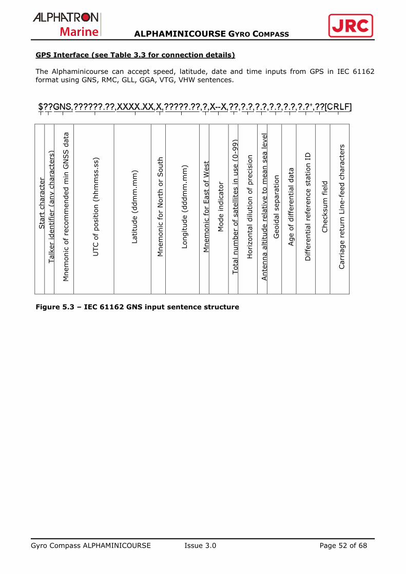
GPS Interface (see Table 3.3 for connection details)
The Alphaminicourse can accept speed, latitude, date and time inputs from GPS in IEC 61162
format using GNS, RMC, GLL, GGA, VTG, VHW sentences.
S
tart
chara
cte
r
Talk
er
identifier
(any c
hara
cte
rs)
Mnem
onic
of
recom
mended m
in G
NSS d
ata
UTC o
f positio
n (
hhm
mss.s
s)
Latitu
de (
ddm
m.m
m)
Mnem
onic
for
Nort
h o
r South
Longitude (
dddm
m.m
m)
Mnem
onic
for
East
of W
est
Mode indic
ato
r
Tota
l num
ber
of
sate
llites in u
se (
0-9
9)
Horizonta
l dilution o
f pre
cis
ion
Ante
nna a
ltitude r
ela
tive t
o m
ean s
ea level
Geoid
al separa
tion
Age o
f diffe
rential data
Diffe
rential re
fere
nce s
tation I
D
Checksum
fie
ld
Carr
iage r
etu
rn L
ine-f
eed c
hara
cte
rs
Figure 5.3 – IEC 61162 GNS input sentence structure

Gyro Compass ALPHAMINICOURSE Issue 3.0 Page 53 of 68
ALPHAMINICOURSE GYRO COMPASS
Sta
rt c
hara
cte
r
Talk
er
identifier
(any c
hara
cte
rs)
Mnem
onic
for
recom
mended m
in G
PS
data
UTC o
f positio
n (
hhm
mss.s
s)
Sta
tus,
A=
valid,
V=
Nav.R
eceiv
er
warn
ing
Latitu
de (
ddm
m.m
m)
Mnem
onic
for
Nort
h a
nd S
outh
Longitude (
dddm
m.m
m)
Mnem
onic
for
East
or
West
Gro
und s
peed in k
nots
Cours
e o
ver
gro
und in d
egre
es
Date
of
fix
Magnetic v
ariation in d
egre
es
Magnetic v
ariation indic
ato
r East
or
West
Mode indic
ato
r
Carr
iage r
etu
rn L
ine feed c
hara
cte
r
Figure 5.4 - IEC 61162 RMC input sentence structure
Sta
rt c
hara
cte
r
Talk
er
identifier
(any c
hara
cte
rs)
Mnem
onic
for
geogra
phic
al la
titu
de a
nd
longitude
Latitu
de (
ddm
m.m
m)
Mnem
onic
for
Nort
h o
r South
Longitude (
dddm
m.m
m)
Mnem
onic
for
East
or
West
UTC o
f positio
n (
hhm
mss.s
s)
Sta
tus
Mode indic
ato
r
Carr
iage r
etu
rn L
ine-f
eed c
hara
cte
rs
Figure 5.5 - IEC 61162 GLL input sentence structure

Gyro Compass ALPHAMINICOURSE Issue 3.0 Page 54 of 68
ALPHAMINICOURSE GYRO COMPASS
Sta
rt c
hara
cte
r
Talk
er
identifier
(any c
hara
cte
rs)
Mnem
onic
for
GPS f
ix d
ata
UTC o
f positio
n (
hhm
mss.s
s)
Latitu
de (
ddm
m.m
m)
Mnem
onic
for
Nort
h o
r South
Longitude (
dddm
m.m
m)
Mnem
onic
for
East
or
West
GPS q
uality
indic
ato
r
Num
ber
of
sate
llites in u
se (
00-1
2)
Horizonta
l delu
tion o
f pre
cis
ion
Ante
nna a
ltitude r
ela
tive t
o m
ean s
ea level
Mnem
onic
for
mete
rs
Geoid
al separa
tion
Mnem
onic
for
mete
rs
Age o
f diffe
rential G
PS d
ata
Diffe
rential re
fere
nce s
tation (
0000-1
023)
Carr
iage r
etu
rn L
ine feed c
hara
cte
rs
Figure 5.6 - IEC 61162 GGA input sentence structure
Sta
rt c
hara
cte
r
Talk
er
identifier
(any c
hara
cte
rs)
Mnem
onic
for
gro
und c
ours
e a
nd
speed
Cours
e in d
egre
es a
nd t
enth
s
Mnem
onic
for
Tru
e h
eadin
g
Cours
e in d
egre
es a
nd t
enth
s
Mnem
onic
for
Magnetic h
eadin
g
Speed in k
nots
Mnem
onic
for
knots
Speed in k
m/h
Mnem
onic
for
km
/h
Mode indic
ato
r
Carr
iage r
etu
rn L
ine-f
eed c
hara
cte
rs
Figure 5.7 - IEC 61162 VTG input sentence structure

Gyro Compass ALPHAMINICOURSE Issue 3.0 Page 55 of 68
ALPHAMINICOURSE GYRO COMPASS
Sta
rt c
hara
cte
r
Talk
er
identifier
(any c
hara
cte
rs)
Mnem
onic
for
vecto
r headin
g a
nd w
ate
r speed
Headin
g in d
egre
es a
nd t
enth
s
Mnem
onic
for
Tru
e h
eadin
g
Headin
g in d
egre
es a
nd t
enth
s
Mnem
onic
for
Magnetic h
eadin
g
Speed in k
nots
Mnem
onic
for
knots
Speed in k
m/h
Mnem
onic
for
km
/h
Carr
iage r
etu
rn L
ine-f
eed c
hara
cte
rs
Figure 5.8 - IEC 61162 VHW input sentence structure
Log Interface (see Table 3.3 for connection details)
The Alphaminicourse can accept speed inputs at the log interface in IEC 61162 format using VВW,
VTG and VHW sentences.
Sta
rt c
hara
cte
r
Talk
er
identifier
(any c
hara
cte
rs)
Mnem
onic
for
gro
und s
peed/w
ate
r speed
Longitudin
al w
ate
r speed in k
nots
Tra
nsvers
e g
round s
peed
Sta
tus:
wate
r speed,
A=
valid,
V=
invalid
Longitudin
al gro
und s
peed in k
nots
Tra
nsvers
e g
round s
peed in k
nots
Sta
tus:
gro
und s
peed,
A=
valid,
V=
invalid
Tra
nsvers
e w
ate
r speed o
f ste
rn in k
nots
Sta
tus:
wate
r speed,
A=
valid,
V=
invalid
Tra
nsvers
e g
round s
peed o
f ste
rn in k
nots
Sta
tus:
ste
rn g
round s
peed,
A=
valid,
V=
invalid
Checksum
fie
ld
Carr
iage r
etu
rn L
ine-f
eed c
hara
cte
r
Figure 5.9 - IEC 61162 VBW input sentence structure

Gyro Compass ALPHAMINICOURSE Issue 3.0 Page 56 of 68
ALPHAMINICOURSE GYRO COMPASS
Sta
rt c
hara
cte
r
Talk
er
identifier
(any c
hara
cte
rs)
Mnem
onic
for
gro
und c
ours
e a
nd s
peed
Cours
e in d
egre
es a
nd t
enth
s
Mnem
onic
for
Tru
e h
eadin
g
Cours
e in d
egre
es a
nd t
enth
s
Mnem
onic
for
Magnetic h
eadin
g
Speed in k
nots
Mnem
onic
for
knots
Speed in k
m/h
Mnem
onic
for
km
/h
Mode indic
ato
r
Carr
iage r
etu
rn L
ine-f
eed c
hara
cte
r Figure 5.10 - IEC 61162 VTG input sentence structure
Sta
rt c
hara
cte
r
Talk
er
identifier
(any c
hara
cte
rs)
Mnem
onic
for
vecto
r headin
g a
nd w
ate
r speed
Headin
g in d
egre
es a
nd t
enth
s
Mnem
onic
for
Tru
e h
eadin
g
Headin
g in d
egre
es a
nd t
enth
s
Mnem
onic
for
Magnetic h
eadin
g
Speed in k
nots
Mnem
onic
for
knots
Speed in k
m/h
Mnem
onic
for
km
/h
Carr
iage r
etu
rn L
ine-f
eed c
hara
cte
r
Figure 5.11 - IEC 61162 VHW input sentence structure
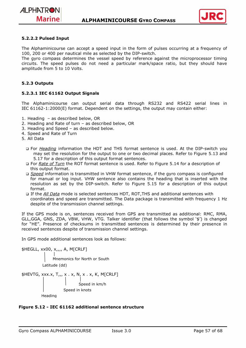
Gyro Compass ALPHAMINICOURSE Issue 3.0 Page 57 of 68
ALPHAMINICOURSE GYRO COMPASS
5.2.2.2 Pulsed Input
The Alphaminicourse can accept a speed input in the form of pulses occurring at a frequency of
100, 200 or 400 per nautical mile as selected by the DIP-switch.
The gyro compass determines the vessel speed by reference against the microprocessor timing
circuits. The speed pulses do not need a particular mark/space ratio, but they should have
amplitude from 5 to 10 Volts.
5.2.3 Outputs
5.2.3.1 IEC 61162 Output Signals
The Alphaminicourse can output serial data through RS232 and RS422 serial lines in
IEC 61162-1:2000(Е) format. Dependent on the settings, the output may contain either:
1. Heading – as described below, OR
2. Heading and Rate of turn – as described below, OR
3. Heading and Speed – as described below.
4. Speed and Rate of Turn
5. All Data
For Heading information the HDT and THS format sentence is used. At the DIP-switch you
may set the resolution for the output to one or two decimal places. Refer to Figure 5.13 and
5.17 for a description of this output format sentences.
For Rate of Turn the ROT format sentence is used. Refer to Figure 5.14 for a description of
this output format.
Speed information is transmitted in VHW format sentence, if the gyro compass is configured
for manual or log input. VHW sentence also contains the heading that is inserted with the
resolution as set by the DIP-switch. Refer to Figure 5.15 for a description of this output
format.
If the All Data mode is selected sentences HDT, ROT,THS and additional sentences with
coordinates and speed are transmitted. The Data package is transmitted with frequency 1 Hz
despite of the transmission channel settings.
If the GPS mode is on, sentences received from GPS are transmitted as additional: RMC, RMA,
GLL,GGA, GNS, ZDA, VBW, VHW, VTG. Talker identifier (that follows the symbol ‘$’) is changed
for “HE”. Presence of checksums in transmitted sentences is determined by their presence in
received sentences despite of transmission channel settings.
In GPS mode additional sentences look as follows:
$HEGLL, xx00, x,,,, A, M[CRLF]
$HEVTG, xxx.x, T,,, x . x, N, x . x, K, M[CRLF]
Figure 5.12 - IEC 61162 additional sentence structure
Mnemonics for North or South
Latitude (dd)
Speed in km/h
Heading
Speed in knots

Gyro Compass ALPHAMINICOURSE Issue 3.0 Page 58 of 68
ALPHAMINICOURSE GYRO COMPASS
Accuracy of heading and presence of checksums is determined by transmission channel settings.
Sta
rt c
hara
cte
r
Talk
er
identifier
(any c
hara
cte
rs)
Mnem
onic
for
Tru
e h
eadin
g p
resent
Headin
g in d
egre
es a
nd t
enth
s
Mnem
onic
for
Tru
e h
eadin
g
Carr
iage r
etu
rn L
ine-f
eed c
hara
cte
r
Figure 5.13 - IEC 61162 HDT output sentence structure
Sta
rt c
hara
cte
r
Talk
er
identifier
Mnem
onic
for
Rate
of
Turn
Rate
of tu
rn °
/m (
negative f
or
port
turn
)
Sta
tus:
A=
valid,
V=
invalid
Carr
iage r
etu
rn L
ine-f
eed c
hara
cte
r
Figure 5.14 - IEC 61162 ROT output sentence structure
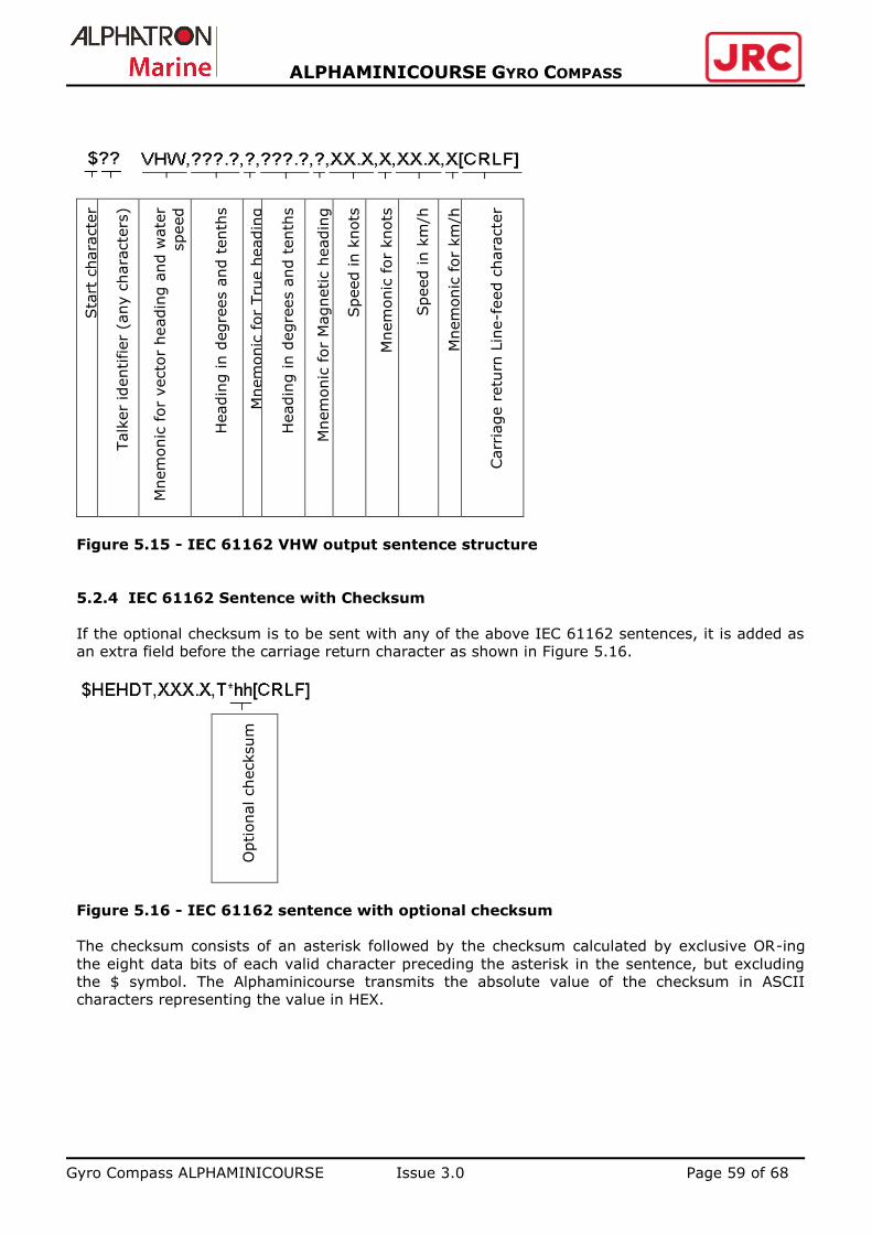
Gyro Compass ALPHAMINICOURSE Issue 3.0 Page 59 of 68
ALPHAMINICOURSE GYRO COMPASS
Sta
rt c
hara
cte
r
Talk
er
identifier
(any c
hara
cte
rs)
Mnem
onic
for
vecto
r headin
g a
nd w
ate
r
speed
Headin
g in d
egre
es a
nd t
enth
s
Mnem
onic
for
Tru
e h
eadin
g
Headin
g in d
egre
es a
nd t
enth
s
Mnem
onic
for
Magnetic h
eadin
g
Speed in k
nots
Mnem
onic
for
knots
Speed in k
m/h
Mnem
onic
for
km
/h
Carr
iage r
etu
rn L
ine-f
eed c
hara
cte
r
Figure 5.15 - IEC 61162 VHW output sentence structure
5.2.4 IEC 61162 Sentence with Checksum
If the optional checksum is to be sent with any of the above IEC 61162 sentences, it is added as
an extra field before the carriage return character as shown in Figure 5.16.
Optional checksum
Figure 5.16 - IEC 61162 sentence with optional checksum
The checksum consists of an asterisk followed by the checksum calculated by exclusive OR-ing
the eight data bits of each valid character preceding the asterisk in the sentence, but excluding
the $ symbol. The Alphaminicourse transmits the absolute value of the checksum in ASCII
characters representing the value in HEX.

Gyro Compass ALPHAMINICOURSE Issue 3.0 Page 60 of 68
ALPHAMINICOURSE GYRO COMPASS
In accordance with the standard IEC 61162-1:2010 for the digital heading transmission it is
recommended to use the THS sentence instead of HDT.
$HETHS ,XXX.X, a*hh [CRLF]
Note – Mode identifier
A = autonomous
E = computed (accurate trajectory calculation)
M = manual input
S = simulation mode
V = data not valid (including idle mode)
Figure 5.17 - IEC 61162 THS sentence structure
In the mode All Data the gyro compass failures are transmitted as following:
$HEALR, ,240, A ,x, sss<CR><LF>
$HEALF, 1, 1, 0, ,B, ,x, ,240, y, 1, 0, sss,<CR><LF> $HEALC,1 ,1 ,0 ,n , {,240, y, 1}…<CR><LF>
Where x - acknowledgement indicator (V – No, A – yes);
y – failure code (see Table 5.1);
sss – failure textual description (see Table 5.1);
n – number of failures;
{} – identifier of one failure in the list of failures;
… - list of failures (if more than one).
Figure 5.18 - IEC 61162 ALR, ALF, ALC outputs sentence structure
Table 5.1 – Failure codes and textual descriptions
Code Text Description
1 Servo System Servo System failure
2 DSP Signal processor failure
3 RDC Angle-to-digit convertor failure
4 Power Failure of internal power supply
5 GPS No GPS signal or invalid data
6 LOG No LOG signal or blockage
True Heading in degrees
Mode identifier

Gyro Compass ALPHAMINICOURSE Issue 3.0 Page 61 of 68
ALPHAMINICOURSE GYRO COMPASS
5.2.5 Other Output Formats
5.2.5.1 Resolver Output (option)
The resolver heading output is available continuously at Х11 connector on the rear panel when
the gyro compass is powered-on. The connection details are given in the Table 3.4. This output
with the maximum voltage 2V per phase is taken from a 1:1 resolver where it comes directly
from the gyro compass azimuth gimbal. The resolver reference voltage is 10V, 400Hz.
Electrical loading specifications:
not less than 5 kOhms between Х11/4 and Х11/3, Х11/5 and Х11/3;
Not less than 1 kOhm between Х11/6 and Х11/7.
5.2.5.2 Stepper Output
Stepper S-code output is available continuously at Х9 connector on the rear panel while the gyro
compass is powered-on. See the connection details in the Table 3.4.
The stepper output is a TTL compatible S-code signal with a 10mA sink capacity.
5.2.5.3 Rate of Turn (option)
The ROT output is calculated by the internal processor updated at 20 Hz and made available
continuously at Х10 connector on the rear panel while the gyro compass is powered-on. Refer to
the Table 3.4 for connection details.
The ROT output is an analogue voltage in the range ±10V that represents the rate of turn:
±30 °/min; ±60 °/min; ±90 °/min; ±120 °/min; ±180 °/min; ±300 °/min; ±1200 °/min.
Particular value is set on the Control Unit.
Positive rates of turn are to starboard.

Gyro Compass ALPHAMINICOURSE Issue 3.0 Page 62 of 68
ALPHAMINICOURSE GYRO COMPASS
6 MAINTENANCE
CAUTION!
Inappropriate tampering with the internal controls and components of the gyro
compass can lead to damage or serious performance degradation.
NEVER open the gyro compass cover or make any adjustments inside the gyro
compass unless one is a fully Alphatron Authorized Service Agent.
There is little need for user maintenance on the Alphaminicourse and one should never need to
remove the cover.
Gyro compass maintenance includes inspection of the Alphaminicourse external appearance,
security of attachment, condition of cables and reliability of their connection.
If the gyro compass is not used for a period of 6 months and more (e.g. the vessel is laid up for
repair), the compass should be run for 30 minutes at intervals not less than 6 months.
6.1 Gyro compass Alphaminicourse drift adjustment
Periodic maintenance of the gyro compass including drift adjustment is carried out once a year
after its installation on the vessel as well as after repair or a long idle time. Drift compensation is
made when the vessel is moored to the berth.
Switch on the gyro compass in accordance with the procedure of the p.4.2 of the Manual. On the
control panel set the speed 0 knots and the local latitude manually or use the GPS mode. In 12
hours take the reading of the current heading Hg from the control panel. By taking the bearing
determine the gyro compass correction value H:
H = Hb – Hg ,
where Hb – the vessel heading received as a result of direction finding,
Hg – the current heading of the vessel in accordance with gyro compass.
Switch off the gyro compass. In 5 minutes set the GC into the adjustment mode by pressing at
first the buttons ▲ and ▼ and then the button . . In this mode the gyro compass and the
servo system are de-energized. The display will show:
D - 0.1
With the help of ▲ and ▼buttons set the value of correction. The input range is from –9.9 to 9.9
degrees. By briefly pressing the buttons «LAT» and «SPEED» simultaneously the gyro compass
will be set into GC (normal gyro compassing) mode with the new value of the horizontal drift.
Please note that when pressing the buttons «LAT» and «SPEED» for too long , <OUT1> will
appear. Scroll with ▲ and ▼ up to <EXIT> and then press «LAT» to accept. The gyro compass
will restart, keep in mind that the drift correction made is stored.
After the adjustment the gyro compass shall operate in the GC mode not less than 5 hours and
then the gyro compass correction value is determined once again. It should not exceed ± 0.2
otherwise the adjustment is repeated.
C
orr
ection
Sig
n o
f corr
ection
Valu
e o
f corr
ection

Gyro Compass ALPHAMINICOURSE Issue 3.0 Page 63 of 68
ALPHAMINICOURSE GYRO COMPASS
6.2 Built-in Test Equipment
The Alphaminicourse performs a self-test routine during the initialization sequence and monitors
its status continually during normal operation. Any deviation from normal operation appears as an
error message with the indication of cause on the 4-character display.
A list of messages including two warning codes and five failure codes that are delivered by the
built-in test equipment in case of the gyro compass fault is given in the sub-section 3.4.3. The 4-
character display will show one of the failure messages and the alarm will sound. If the built-in
test equipment detects a fault, use the table 6.1 to investigate the cause.
Table 6.1 – List of failure messages
Failure
Code Probable Cause Remedy
TEST and
audible
signal
Component failure The failure is due to the component
damage and cannot be corrected in the
field; is to be sent to the manufacturer
or to the approved service center
SS
Gyroscope or servo system
failure
The failure is due to the component
damage and cannot be corrected in the
field; is to be sent to the manufacturer
or to the approved service center
BETA 1) Improper setting and/ or
adjustment of the gyro
compass
2) Component failure
1) Adjust the gyro compass properly (set
the correct latitude and speed)
2) Cannot be corrected in the field. is to
be sent to the manufacturer or to the
approved service center
RDC
Resolver-digital converter
failure
The failure is due to the component
damage and cannot be corrected in the
field; is to be sent to the manufacturer
or to the approved service center
DSP
Failure of a signal processor
on the analog board
The failure is due to the component
damage and cannot be corrected in the
field.
PWR
Failure of the power supply
board
The failure is due to the component
damage and cannot be corrected in the
field
NО+GPS Loss or distortion of GPS
receiver signal
Check the link and polarity of connection.
Use manual correction if case the correct
operation of GPS cannot be provided.
ERR+GPS
Invalid GPS signal (invalid
checksum)
The link may be not standard. Use manual
correction if case the correct operation of
GPS cannot be provided.
????+GPS
The unit does not recognize
the GPS signal
Adjust the GPS receiver for transmission
of the sentences acceptable to the gyro
compass.
NO+LOG Loss or distortion of the log
signal
Check the link and polarity of connection.
????+LOG
Log signal is not recognized Adjust the log for transmission of the
sentences acceptable to the gyro
compass.
ERR+LOG
Invalid log signal (invalid
checksum)
The link may be not standard.
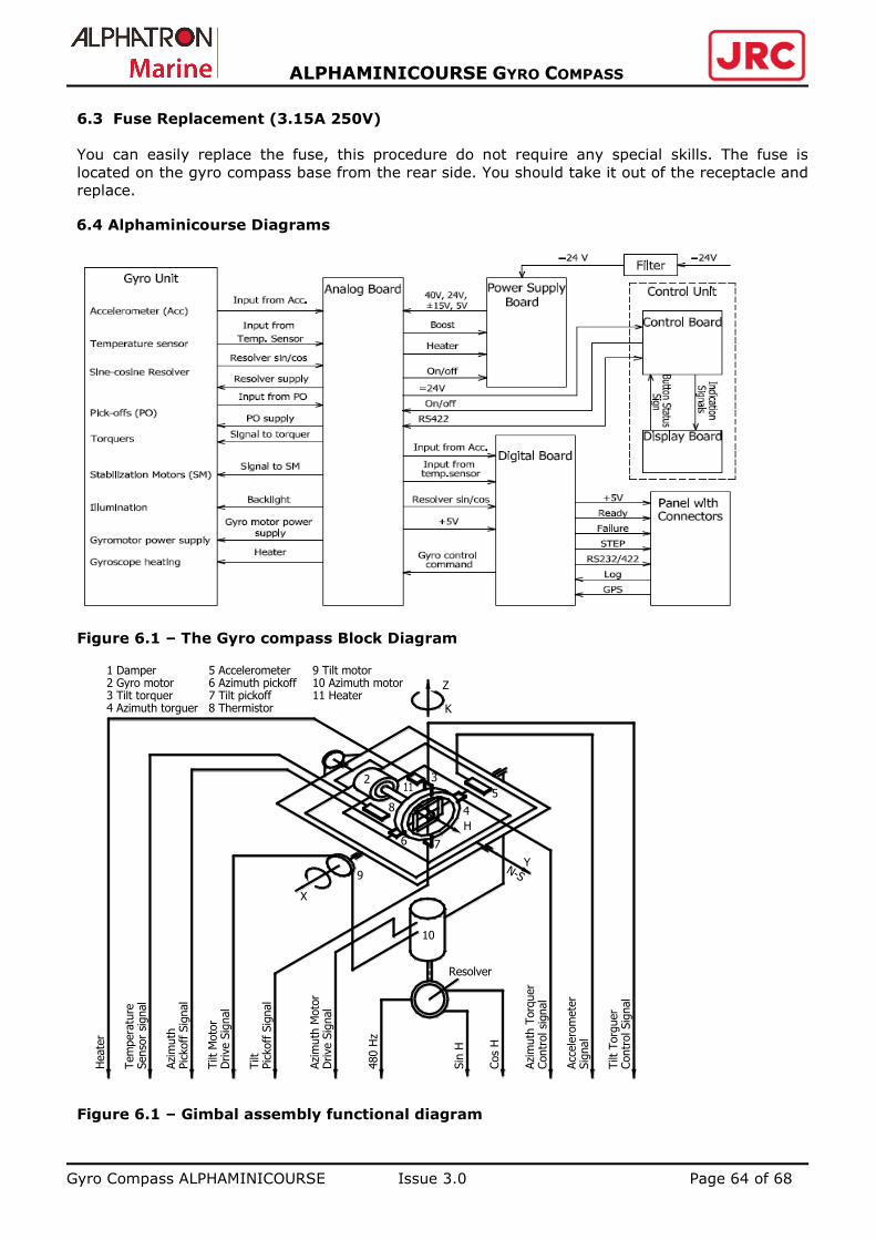
Gyro Compass ALPHAMINICOURSE Issue 3.0 Page 64 of 68
ALPHAMINICOURSE GYRO COMPASS
6.3 Fuse Replacement (3.15А 250V)
You can easily replace the fuse, this procedure do not require any special skills. The fuse is
located on the gyro compass base from the rear side. You should take it out of the receptacle and
replace.
6.4 Alphaminicourse Diagrams
Figure 6.1 – The Gyro compass Block Diagram
Figure 6.1 – Gimbal assembly functional diagram
5 Accelerometer6 Azimuth pickoff7 Tilt pickoff8 Thermistor
2
8
K
Z
N-SY
H
6
4
7
X
9
Resolver
Azi
muth
480 H
z
10
Pic
koff
Sig
nal
Azi
muth
Moto
rD
rive S
ignal
Drive S
ignal
Tilt
Moto
r
Sin
H
Cos
H
Tilt
Pic
koff
Sig
nal
Azi
muth
Torq
uer
Contr
ol si
gnal
Senso
r si
gnal
Tem
pera
ture
Heate
r
Acc
ele
rom
ete
rSig
nal
Tilt
Torg
uer
Contr
ol Sig
nal
5
3
9 Tilt motor10 Azimuth motor11 Heater
4 Azimuth torguer3 Tilt torquer2 Gyro motor1 Damper

Gyro Compass ALPHAMINICOURSE Issue 3.0 Page 65 of 68
ALPHAMINICOURSE GYRO COMPASS
7 TRANSPORTATION
7.1 Dual-use good
The Alphaminicourse Gyrocompass is classified as a dual-use good: They can be used for non-
military and military applications. As consequence the products are subjected to dual-use goods
export control procedures:
Alphatron can be delivered the Alphaminicourse freely to The Netherlands or any country of
the European Union.
Alphatron can export NEW Alphaminicourse Gyrocompasses under its own Community
General Export Authorization EU001 to the following countries: Australia, Canada, Japan,
New Zealand, Norway, Switzerland (including Liechtenstein) and United States of America.
Alphatron can export repaired Alphaminicourse Gyrocompasses under its own Community
General Export Authorization EU003 to the following countries: Albania, Argentina, Bosnia
and Herzegovina, Brazil, Chile, China (including Hong Kong and Macao), Croatia, The former
Yugoslav Republic of Macedonia. French Overseas Territories, Iceland, India, Kazakhstan,
Mexico, Montenegro, Morocco, Russia, Serbia, Singapore, South Africa, South Korea,
Tunisia, Turkey, Ukraine, Unites Arab Emirates.
The Alphaminicourse can be exported to other countries but only through the preliminary
issuance of an individual export license by the Dutch authorities.
7.2 Transport
The gyro compass is packed into an special designed Alphatron box and can be transported
by any means of transportation to any distance.
Transportation boxes with the gyro compass set shall be protected against atmosphere
precipitation and shall be fastened to prevent fall, jumps, movements and mutual collision of
units. The boxes should be handled during transportation, carriage and loading in accordance
with the inscriptions made on the boxes.
Ambient temperature during transportation shall be within the range from -60°C to +70°C.
All Gyro compasses leaving Alphatron are secured on an pallet and marked with shockwatch
indicators. If the shockwatch indicators are red after transportation, please contact Alphatron.
Clients who have received a replacement Gyro compass need to use its special designed
Alphatron box to transport there defected Gyro compass back to Alphatron. Please see
below pictures how to pack.
Gyro Compass ALPHAMINICOURSE Issue 3.0 Page 66 of 68
ALPHAMINICOURSE GYRO COMPASS
8 STORAGE
The gyro compass shall be stored in a lockable heated space equipped with humidity and
temperature indicators. The maximum relative humidity in the storage area is 85%.
The indoor temperature shall be within the range +5С to +30 С. The distance to the heaters
shall prevent their direct influence on the gyro compass.
If the gyro compass is stored in the package, it should be positioned in accordance with the
inscriptions on the box.
In and near the storage area there must be no alkali, acids or other aggressive substances.
The gyro compass storage time without the re-preservation is three years.
9 SERVICE
9.1 Self Service
As mentioned on page 62 there is little need for user maintenance on the Alphaminicourse and
one should never need to remove the cover. The gyro compass cover may only be opened by fully
Alphatron Authorized agents to make any adjustments or repairs to prevent loss of warranty.
Please keep in mind that drift adjustment as periodic maintenance of the Alphaminicourse gyro
compass should be carried out every year after its installation on the vessel as well as after repair
or a long idle time.
Drift compensation can be performed when the vessel is moored to the berth, for the operating
procedure please use page 62.
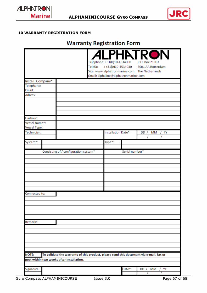
Gyro Compass ALPHAMINICOURSE Issue 3.0 Page 67 of 68
ALPHAMINICOURSE GYRO COMPASS
10 WARRANTY REGISTRATION FORM

Gyro Compass ALPHAMINICOURSE Issue 3.0 Page 68 of 68
ALPHAMINICOURSE GYRO COMPASS
11 GYRO SETTINGS REGISTRATION FORM


