
Honghai SongYawei Wang, Kent Holland, Ken Schrock, Saravan
ChandrasekaranFRIB/MSU & SJTU
14-17 June 2015, SJTU Xuhui Campus
Alternative Approach to ReBCO HTS MagnetOperation and Protection:
- Influence of Turn-to-turn Equivalent Resistivity and CoilSize on Fast-discharge and Ramping of Metallic Insulation
HTS Coils
This material is based upon work supported by the U.S. Department of Energy Office of Science under Cooperative Agreement DE-SC0000661, the State of Michigan and MichiganState University. Michigan State University designs and establishes FRIB as a DOE Office of Science National User Facility in support of the mission of the Office of Nuclear Physics.
Honghai SongYawei Wang, Kent Holland, Ken Schrock, Saravan
ChandrasekaranFRIB/MSU & SJTU
14-17 June 2015, SJTU Xuhui Campus

KIT/ITEP: F. Grilli, V. R. ZermenoMIT: Y. Iwasa, S. HahnNCSU: W.K. Chan, J. SchwartzSJTU: Z. Jin, Z. Hong, Y. LiFRIB/MSU: E. Burkhardt, A. Zeller, T. BordenNMHFL: H. Weijers, J. Lu, D. LarbalestierBNL: R. Gupta. P. WandererNIMS: Y. MIYOSHIPolyTech: F. Sirois
Acknowledgement
Workshop on pp Collider Magnets
KIT/ITEP: F. Grilli, V. R. ZermenoMIT: Y. Iwasa, S. HahnNCSU: W.K. Chan, J. SchwartzSJTU: Z. Jin, Z. Hong, Y. LiFRIB/MSU: E. Burkhardt, A. Zeller, T. BordenNMHFL: H. Weijers, J. Lu, D. LarbalestierBNL: R. Gupta. P. WandererNIMS: Y. MIYOSHIPolyTech: F. Sirois
H. Song – HTS Magnet Ramping and Protection Slide 2

MagLab Claims Record with ReBCOSuperconducting Magnet
This ReBCO test coil helped the MagLabset a new world record for superconductingmagnets: 27 Tesla.10 June, 2015
Workshop on pp Collider Magnets H. Song – HTS Magnet Ramping and Protection Slide 3
HTS (12 T) + LTS(15 T)

Introduction• Traditional Insulation• Metallic insulation (Stainless steel or Cu insulation)
Development of small-scale Stainless steel insulated HTS coil• Coil design, winding, testing• Fast-discharge experimental results and analysis• Equivalent resistivity calculation
Prediction of ramping behaviors of large-scale HTS coils• Dependence of ramping rate, coil size, equivalent turn-to-turn resistivity…
Two applications• Multiple small-diameter coils for NMR applications• Large coils for accelerator and induction heater applications
Outline
Workshop on pp Collider Magnets
Introduction• Traditional Insulation• Metallic insulation (Stainless steel or Cu insulation)
Development of small-scale Stainless steel insulated HTS coil• Coil design, winding, testing• Fast-discharge experimental results and analysis• Equivalent resistivity calculation
Prediction of ramping behaviors of large-scale HTS coils• Dependence of ramping rate, coil size, equivalent turn-to-turn resistivity…
Two applications• Multiple small-diameter coils for NMR applications• Large coils for accelerator and induction heater applications
H. Song – HTS Magnet Ramping and Protection Slide 4

ReBCO Conductor (2G) HTS Coil
• Rare Earth-based, second-Generation High-TemperatureSuperconductor wire– Robust wire characteristics due to
Hastelloy substrate– Wide temperature range ( 4K<T<65K)
• HTS Coils– React & Wind– Flexibility in coil winding– Suitable for a wide variety of
applications: energy, industrial,science & research, military & defense,transportation
SuperPower
Workshop on pp Collider Magnets H. Song – HTS Magnet Ramping and Protection
• Rare Earth-based, second-Generation High-TemperatureSuperconductor wire– Robust wire characteristics due to
Hastelloy substrate– Wide temperature range ( 4K<T<65K)
• HTS Coils– React & Wind– Flexibility in coil winding– Suitable for a wide variety of
applications: energy, industrial,science & research, military & defense,transportation
SuNAM, 26.4 TMAGLAB, 27 T
Slide 5

Voltage across normal zone is too small to detect (Earlier quenchstage)Normal zone propagation in HTS too slow (Quench)Most available test data based on short sample, small coil
• Large # of stacked HTS coil for NMR ( 10 – 20 coils), few test data available• Large-scale HTS coil for accelerator dipole or induction heater, no test data
available
Traditional detect-quench-protection approach does not seem to workfor the HTS magnet Alternative approaches• Novel winding• Better understanding• Systematic modeling and simulation• Prototyping and extensive tests• Great care
Challenges in HTS Magnet Protection and Operation
Workshop on pp Collider Magnets
Voltage across normal zone is too small to detect (Earlier quenchstage)Normal zone propagation in HTS too slow (Quench)Most available test data based on short sample, small coil
• Large # of stacked HTS coil for NMR ( 10 – 20 coils), few test data available• Large-scale HTS coil for accelerator dipole or induction heater, no test data
available
Traditional detect-quench-protection approach does not seem to workfor the HTS magnet Alternative approaches• Novel winding• Better understanding• Systematic modeling and simulation• Prototyping and extensive tests• Great care
H. Song – HTS Magnet Ramping and Protection Slide 6

Traditional insulation used in LTS superconductor wires, Kapton, Fovar• Recently proposed ZnO dope polyimide insulation• HTS normal zone propagates still slow ( ~cm/second)• High risks for large-scale magnets
Metallic strip insulation• No turn-to-turn insulation, conductors are wound directly
» Cu/Cu contact, (even soldered Cu)» Soldered Cu/Cu contact
• Co-wound with metal strips» Cu strips, similar to the No-insulation contact, but two contact layers» Stainless steel strips, high resistivity
Metallic-Insulation HTS Coil and Its Winding
Workshop on pp Collider Magnets
Traditional insulation used in LTS superconductor wires, Kapton, Fovar• Recently proposed ZnO dope polyimide insulation• HTS normal zone propagates still slow ( ~cm/second)• High risks for large-scale magnets
Metallic strip insulation• No turn-to-turn insulation, conductors are wound directly
» Cu/Cu contact, (even soldered Cu)» Soldered Cu/Cu contact
• Co-wound with metal strips» Cu strips, similar to the No-insulation contact, but two contact layers» Stainless steel strips, high resistivity
H. Song – HTS Magnet Ramping and Protection , Slide 7
Supercond. Sci. Technol.27(2014) 06501
Metallic strip insulation

Fast-discharge Behaviors of HTS CoilStainless Steel Insulation Coils Needs More Detailed Studies
Supercond. Sci. Technol.27(2014) 06501 Co-wound materialKapton, every turnSS, every turnCu, every turnKapton, every 4 turnsSS, every 4 turnsCu, every 4 turnsKapton insulation
Workshop on pp Collider Magnets H. Song – HTS Magnet Ramping and Protection
Kapton Insulation = SS Insulation? (NO)Kapton Insulation = SS Insulation? (NO)
Slide 8

Stainless Steel Insulated HTS Coil- Coil Design
Load line
a1 (ID/2) 50.8 mma2 (OD/2) 67.31 mm
Conductor
Thickness 0.1 mmWidth 4 mm
SS
Thickness 0.025 mmWidth 4.2 mm
Double Pancake Coil (DPC) Co-wound with SS strips
Workshop on pp Collider Magnets H. Song – HTS Magnet Ramping and Protection Slide 9
0.0
0.5
1.0
1.5
2.0
2.5
3.0
0 50 100 150 200 250 300 350
B (T
)
Current I (A)
Load line
Bmax
B2
B0
Ic@40KIc@50K
Width 4.2 mmCell (conductor + SS)
Thickness 0.125 mmWidth 4.2 mm
Cross section 0.525 mm2Coil
ID 101.6 mmOD 134.62 mm
Coil volume 25729.6 mm3
Total conductor length 49008.7 mm49.00 m
Total turns 132.08
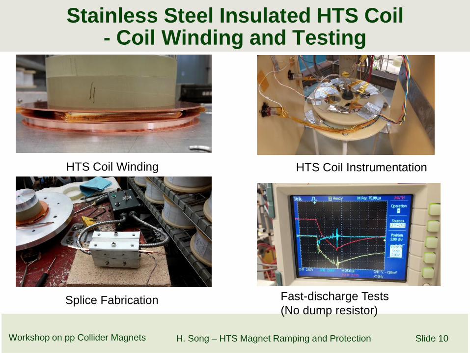
Stainless Steel Insulated HTS Coil- Coil Winding and Testing
HTS Coil Winding HTS Coil Instrumentation
Workshop on pp Collider Magnets H. Song – HTS Magnet Ramping and Protection Slide 10
Splice Fabrication Fast-discharge Tests(No dump resistor)

Stainless-Steel Insulated Coil VS Cu Insulation Coil
Parameters Tape1 Tape 2 Tape 3Thickness 0.1 mm 0.3 mm 0.25 mmwidth 4.0 mm 4.75 mm 4.2 mmLamination Electroplated Cu Copper/Solder Brass/SolderCo-wound strip SS No NoSubstrate Hastelloy Hastelloy HastelloyIc @ 77K, tape 140 A 220 A 170 A
Table 1.Specifications of thetest ReBCO tapes
Table 2.Specifications of thetest NI coils
Workshop on pp Collider Magnets H. Song – HTS Magnet Ramping and Protection
Parameters Coil 3 Coil 2 Coil 1Coil type DP SP DPTape Tape 1 Tape 2 Tape 3Number of turns 130*2 27 62*2Inner diameter 102 mm 100 mm 245 mmTension ~5 kg 7 kg 4 kgTotal length of wire 98 m 9.1 m 101 mInductance, Lcoil, cal. 12.1 mH 150μH 8.11 mHBz per amp, cal. 2.64 mT 0.3 mT 0.59 mTIc, coil @77K ~120A@40K 133A@77K 97A@77K
Slide 11

Stainless-Steel Insulated Coil VS Cu Insulation CoilFast-discharge V(I) Curve Time constant τ Equivalent ρ
EquivalentContactResistivity
Coil 1 (SS)7469 µΩ∙cm2
Coil 2 (Cu)27.5 µΩ∙cm2
Coil 1 (SS Insulated) Coil 2 (Cu) Coil 3 (Brass)
Workshop on pp Collider Magnets H. Song – HTS Magnet Ramping and Protection Slide 12
Sudden discharging test of three NI coils. Log(V) vs Time
27.5 µΩ∙cm2
Coil 3 (Brass)88.0 µΩ∙cm2
Coil 1 (SS Insulated) Coil 2 (Cu) Coil 3 (Brass)
~100 times more

Benefits of contact resistance for fast-discharge protection becomesdisadvantage during charge ramping To clarify one of the most critical concerns Will the metallic
insulation HTS coils have settle-off problems?Apply equivalent insulation resistivity from small coils predict
ramping behaviors in larger coilsHTS coil modeling – a hybrid modeling (Critical State + Metallic
Insulation)
Ramping Behaviors of Metallic Insulation HTSCoil
Workshop on pp Collider Magnets
Benefits of contact resistance for fast-discharge protection becomesdisadvantage during charge ramping To clarify one of the most critical concerns Will the metallic
insulation HTS coils have settle-off problems?Apply equivalent insulation resistivity from small coils predict
ramping behaviors in larger coilsHTS coil modeling – a hybrid modeling (Critical State + Metallic
Insulation)
H. Song – HTS Magnet Ramping and Protection Slide 13
Current input
Currentoutput
Circuit Node
IndependentCircuit Mesh
2D Critical State Current density profile Equivalent circuit grid model

Magnetic field B lags coil zzimuthally flowing current!
Ramping Behaviors Characterization inMetallic Insulation HTS Coils
Workshop on pp Collider Magnets H. Song – HTS Magnet Ramping and Protection Slide 14
Power supply

Dependence of Ramping Rate if ρ = 70 µΩ∙cm2
(Typical Cu Strip Co-Winding)
Workshop on pp Collider Magnets H. Song – HTS Magnet Ramping and Protection Slide 15
Current vs TimeItransport: total power supply currentIazimuthal : current along lengthIradial: current along radius
Coil Voltage vs Time Field lags the current
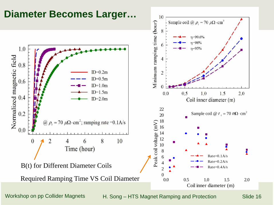
Diameter Becomes Larger…
Workshop on pp Collider Magnets H. Song – HTS Magnet Ramping and Protection Slide 16
B(t) for Different Diameter Coils
Required Ramping Time VS Coil DiameterCoil inner diameter (m)
0.0 0.5 1.0 1.5 2.0
Pea
k co
il vo
ltage
(m
V)
02468
10121416182022
Rate=0.1A/s
Rate=0.2A/s
Rate=0.4A/s
2Sample coil @ 70 cmt

Turn-to-turn resistivity (cm2)50 100 150 200 250 300
Min
imum
ram
ping
tim
e (h
our)
0
5
10
15
20
25
30
Opt
imal
ram
ping
rat
e (m
A/s
)
0
2
4
6
8
10
12
14Ramping time (= 99.6%)Optimal ramping rate
@ ID = 2 m
Influence of Turn-to-turn Resistivity
Workshop on pp Collider Magnets
Turn-to-turn resistivity (cm2)50 100 150 200 250 300
Min
imum
ram
ping
tim
e (h
our)
0
5
10
15
20
25
30
Opt
imal
ram
ping
rat
e (m
A/s
)
0
2
4
6
8
10
12
14Ramping time (= 99.6%)Optimal ramping rate
@ ID = 2 m
H. Song – HTS Magnet Ramping and Protection Slide 17
For smaller coils ID=0.1 m, increasingequivalent resistivity reducing ramping time,but the maximum time is ~ 400 s. Cu insulation may be OK for 0.1 ID coil
For larger coils, similar increment inresistivity, but ramping times decreasesfrom 25 hours 2 hours. SS insulation becomes necessary!
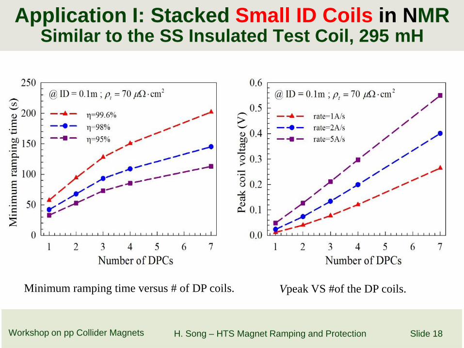
Application I: Stacked Small ID Coils in NMRSimilar to the SS Insulated Test Coil, 295 mH
Workshop on pp Collider Magnets H. Song – HTS Magnet Ramping and Protection Slide 18
Minimum ramping time versus # of DP coils. Vpeak VS #of the DP coils.

NMR Applications: Stacked Small ID Coils
Workshop on pp Collider Magnets H. Song – HTS Magnet Ramping and Protection Slide 19
1) Ramping rate=1 A/s, magnet with 7 DP coils,2) Time resolved distribution of tangential-
component current,3) Difference exits between top and middle coils
1) Total transport current (powersupply)
2) Tangential current in coils 1 – 33) Radial current in coils 1 -3

Magnet:• DP coil: ID = 2 m, 130*2 turns• Magnet: 10 DP coils• Operation: Iop=80A, B =0.4 T (air gap)• Self-inductance: 31 H (without iron), 132 H (with iron)• Preliminary design only for this analysis use (single conductor winding)
Application II – HTS DC Induction Heater
Workshop on pp Collider Magnets H. Song – HTS Magnet Ramping and Protection Slide 20
IEEE TRANS ON ASC, VOL. 25, NO.3,JUNE 2015, 4600305

Application B – HTS DC Induction HeaterCu VS SS Co-winding
Workshop on pp Collider Magnets H. Song – HTS Magnet Ramping and Protection Slide 21
If the coils is wound with Cu stripsRampig time will be up to 200 hours
If the coils is wound with SS stripsRampig time will be below 2 hours

Current Flow Comparison Between(Cu VS SS)
Ramp rate 0.02 A/SRamp rate 0.2 mA/S
Workshop on pp Collider Magnets H. Song – HTS Magnet Ramping and Protection Slide 22
Although in the same pattern, but 100 times shorter in ramping time!Although in the same pattern, but 100 times shorter in ramping time!

Metallic insulation is an effective approach for HTS coil protectionduring quench and other unpredicted accidentsAlthough metallic insulation becomes disadvantage during charge
ramping• Cu insulation is still ok for small diameter coil application (like NMR)• But for large-scale applications, Cu insulation results in much more time (up
to 100 hours) in ramping,» Thus, SS insulation becomes necessary
More studies further needed• Thermal behaviors due to radial current component increased
temperature during charge ramping• Thermal management during fast-discharge needs more complete modeling,
other than MITTs function prediction• Conductors cabling to reduce the magnet inductance
HTS magnet technology needs more R&D as it positively progressestowards broader applications – particularly high energy physics.
Conclusions
Workshop on pp Collider Magnets
Metallic insulation is an effective approach for HTS coil protectionduring quench and other unpredicted accidentsAlthough metallic insulation becomes disadvantage during charge
ramping• Cu insulation is still ok for small diameter coil application (like NMR)• But for large-scale applications, Cu insulation results in much more time (up
to 100 hours) in ramping,» Thus, SS insulation becomes necessary
More studies further needed• Thermal behaviors due to radial current component increased
temperature during charge ramping• Thermal management during fast-discharge needs more complete modeling,
other than MITTs function prediction• Conductors cabling to reduce the magnet inductance
HTS magnet technology needs more R&D as it positively progressestowards broader applications – particularly high energy physics.
H. Song – HTS Magnet Ramping and Protection Slide 23

Thank-You
This material is based upon work supported by the U.S. Department of Energy Office of Science under Cooperative Agreement DE-SC0000661, the State of Michigan and MichiganState University. Michigan State University designs and establishes FRIB as a DOE Office of Science National User Facility in support of the mission of the Office of Nuclear Physics.H. Song – HTS Magnet Ramping and ProtectionSlide 24
Three Dimensional Critical –State Current Density in a 1/8 model of a HTSCoil - On-going Effort

AppendixDefinition of Minimum Ramping Time
Workshop on pp Collider Magnets H. Song – HTS Magnet Ramping and Protection Slide 25


