Alternative strategies to incorporate biomolecules within
electrospun meshes
Prasad Vaidya
Thesis submitted to the faculty of the Virginia Polytechnic Institute and State
University in partial fulfilment of the requirements for the degree of
Masters of Science
In
Chemical Engineering
Aaron S Goldstein, Chair
Abby R. Whittington
Richey M. Davis
12th September 2014
Blacksburg, VA
Keywords: co-axial electrospinning, chitosan, chitosan-alginate microspheres,
RGD, FITC-BSA, bone marrow stromal cells
Copyright © 2014, Prasad Vaidya

Alternative Strategies to incorporate biomolecules within electrospun meshes
Prasad Avdhut Vaidya
Abstract
Rupture of the anterior cruciate ligament (ACL) is one of the most common ligamentous
injuries of the knee. Post rupture, the ACL does not heal on itself due to poor vasculature and
hence surgical intervention is required to treat the ACL. Current surgical management of ACL
rupture consists of reconstruction with autografts or allografts. However, the limitations associated
with these grafts have prompted interest in tissue engineered solutions that combine cells, scaffolds
and stimuli to facilitate ACL regeneration. This thesis describes a ligament tissue engineering
strategy that involves incorporating biomolecules within fibers-based electrospun meshes which
mimics the extra-cellular matrix microarchitecture of ligament. However, challenges exist with
incorporation of biomolecules. Therefore, the goal of this research project was to develop two
techniques to incorporate biomolecules within electrospun meshes: (1) co-axially electrospinning
fibers that support surface-grafting of biomolecules, and (2) co-axially electrospinning fibers
decorated with biomolecule-loaded microspheres.
In the first approach, chitosan was co-axially electrospun on the shell side of poly
caprolactone (PCL) and arginine-glycine-aspartate (RGD) was attached to the electrospun meshes.
Bone marrow stromal cells (BMSCs) attached, spread and proliferated on these meshes. In the
second approach, fluorescein isothiocyanate labelled bovine serum albumin (FITC-BSA) loaded
chitosan-alginate (CS-AL) microspheres were fabricated. The effects of cation to alginate ratio,
type of alginate and concentration of CaCl2 on microsphere size, FITC-BSA loading and release

were systematically evaluated. The CS-AL microspheres were then incorporated into the sheath
phase of co-axially electrospun meshes to achieve microsphere-decorated fiber composite meshes.
The results from these model study suggest that both approaches are tractable for
incorporating biomolecules within fibers-based electrospun meshes. Both these approaches
provide platform for future studies that can focus on ligament-relevant biomolecules such as FGF-
2 and GDF-5.
iii

Author’s Acknowledgements
I would like to thank my advisor Dr. Aaron Goldstein for guiding me throughout my
research with his valuable inputs. I really appreciate his endless efforts in trying to teach me the
importance of transitions in presentations and technical writing. I am sincerely thankful to him for
the painstaking efforts he took in correcting my thesis and suggesting changes to bring the
document in the shape it is today.
I would like to sincerely thank faculty members, staff and students at Virginia Tech. In
particular, I would like to thank Dr. Whittington, Dr. Davis and Dr. Edgar for going out of way
and helping me in designing experiments and suggesting ways to get the microspheres project to
work. I am also grateful to Dr. Grove and Kristina Roth for helping me with covalent conjugation
projects. I would also like to acknowledge Riley Chan, Michael Vaught and Kevin Holshouser for
their help in fabricating set-ups for co-axial electrospinning and dual drum. Without their help, my
two manuscripts would never have been possible. Finally, I am thankful to Dr. Satyavrata
samavedi and Patrick Thayer for teaching lab techniques and helping me with my research.
I am eternally indebted to my family who supported me throughout all my endeavors. My
parents did not oppose my decision to leave India to go the United States to pursue my goals,
despite it was against their will. They have supported me financially, morally and emotionally, and
backed every decision I ever took. No words can express my sincere gratitude for these gestures
of theirs. My elder brother and sister-in-law, who were already in US during my arrival, made my
transition peaceful from India to US and they always made me feel at home in a foreign land. They
have always been available to support me at my hard times in the US. Finally, I would like to thank
my elder sister and my brother-in-law for supporting my decisions at every stage and taking care
of our parents in their time of need, when I could not be available. The smile on faces of my two
iv

nieces have always played a pivotal role in raising my spirits during all my bad days. All of you
have sacrificed so much to see me succeed. Despite that, I could not pursue what I had begun and
I faced one of the biggest set-back in my life. However, I want to assure you that this set-back has
not broken my spirits and will not deter me from setting new goals in my life. In fact, this set-back
has taught me the importance of being available to family as opposed to neglecting the family in
pursuit of the professional goals. Today, I promise you that I won’t let your sacrifices go in vain
and would try to be much more available.
Last but not least, I really appreciate my friends in Blacksburg who have supported me
throughout one of the toughest times of my life (hopefully future does not have times as tough as
last couple of years). Especially, Balachandar Guduri, Priyal Shah, Vireshwar Kumar, Sriram
Malladi and Amuru Sai Dhiraj – I am grateful to you for accommodating me in your homes during
my financial crisis. Amiya Behera, you are the best roommate one could ever hope to have since
you letting me and others spoil the apartment. Thanks for listening to me endlessly talking about
my research and unfairness of life. Thanks for helping me find sublets to reduce my financial
burden. Finally, I will always cherish, the never ending discussions with Parang Saraf, Apoorv
Garg and Ritesh Kumar Soni on weekend nights which also involved some entertainment props.
Those times really helped me fight back through some tough days.
v

Table of Contents
Chapter 1: Background and overview of thesis
1.1 Introduction………………………………………………………………………………..1 1.2 Anterior cruciate ligament (ACL) anatomy…………………………………………….....2 1.3 Medical problems and current available solutions for ACL injuries……………………...5 1.4 Tissue engineering strategies……………………………………………………………...7
1.4.1. Scaffolds…………………………………………………………………..8 1.4.1.1 Biomaterials for scaffolds…………………………………………………8 1.4.1.2 Scaffold fabrication technique.…………………………………………....9
1.4.2. Cell Source……………………………………………………………….12 1.4.3. Biochemical and chemical stimulation…………………………………..14
1.4.3.1 Fibroblast growth factor-2 (FGF-2)……………………………………...14 1.4.3.2 Growth and differentiation factor-5 (GDF-5)……………………………15 1.4.3.3 Arginine-glycine-aspartic acid (RGD) peptide…………………………..16
1.4.4. Summary of tissue engineering and protein or peptide delivery………...17 1.5 Immobilization of biomolecules…………………………………………………………18
1.5.1. Surface modification……………………………………………………..19 1.5.2. Cross linking chemistry………………………………………………….20 1.5.2.1 EDC/NHS chemistry…………………………………………………….21 1.5.2.2 Sulfo SMCC linking chemistry………………………………………….22
1.6 Encapsulation of biomolecules within tissue engineering scaffolds…………………….23 1.6.1 Micro- and nano-particles for delivery of biomolecules…………………24
1.7 Overview of thesis/dissertation………………………………………………………….26
Chapter 2: Surface grafting of chitosan shell, polycaprolactone core fiber meshes to confer bioactivity
Abstract…………………………………………………………………………………..29 2.1 Introduction………………………………………………………………………………30 2.2 Materials and Methods…………………………………………………………………...32
2.2.1 Materials…………………………………………………………………32 2.2.2 Synthesis of FITC-chitosan………………………………………………33 2.2.3 Co-axial electrospinning………………………………………………… 33 2.2.4 Imaging of electrospun meshes…………………………………………..34 2.2.5 Mechanical testing of electrospun meshes………………………………..35 2.2.6 Covalent conjugation to electrospun meshes……………………………..35 2.2.7 Cell attachment and proliferation………………………………………...36 2.2.8 Cell morphology and cytoskeletal organization………………………….37 2.2.9 Statistical Analysis……………………………………………………….38
2.3 Results……………………………………………………………………………………39
vi

2.3.1 Fabrication and characterization of electrospun meshes…………………39 2.3.2 Rhodamine conjugation to coaxially electrospun meshes……………….43 2.3.3 BMSC attachment and proliferation……………………………………..44 2.3.4 Cell morphology and cytoskeletal organization…………………………45
2.4 Discussion………………………………………………………………………………..48 2.5 Conclusions………………………………………………………………………………50
Chapter 3: Co-axial electrospinning chitosan-alginate microspheres to deliver biomolecules in electrospun meshes
Abstract…………………………………………………………………………………..52 3.1 Introduction………………………………………………………………………………53 3.2 Materials and Methods…………………………………………………………………...56
3.2.1 Materials…………………………………………………………………56 3.2.2 Synthesis of FITC-chitosan………………………………………………56 3.2.3 Fabrication of microspheres……………………………………………...57 3.2.4 Effect of processing parameters on microsphere size, loading and release
of FITC-BSA…………………………………………………………….58 3.2.5 Co-axial Electrospinning………………………………………………...59 3.2.6 Characterization of electrospun meshes………………………………….60 3.2.7 Co-axial electrospinning of chitosan-alginate microspheres…………….61
3.3 Results and Discussions………………………………………………………………….61 3.3.1 Effect of processing parameters on microsphere size……………………61 3.3.2 Loading and Release of FITC-BSA from microspheres…………………63 3.3.3 Co-axial electrospinning…………………………………………………70 3.3.4 Characterization of electrospun meshes………………………………….71 3.3.5 Co-axial electrospinning of microspheres…………………………….....74
3.4 Conclusions………………………………………………………………………………77
Chapter 4: Summary and Future Directions
4.1 Summary of the Results………………………………………………………………….78 4.2 Future Recommendations………………………………………………………………..79
4.2.1 Covalent conjugation of biomolecules to promote variety of cellular responses………………………………………………………………..79
4.2.2 Controlled release of biomolecules from electrospun mesh..………….. 80 4.2.2.1 Preliminary data with FGF-2…………………………………………… 81
4.2.3 Electrospun meshes containing gradients of peptides or proteins……….83 4.2.4 Fabrication of 3-D scaffolds……………………………………………..85
vii
4.3 Summary of the chapter…………………………………………………………………..86 4.4 Concluding remarks of the thesis…………………………………………………………86
Bibliography………………………………………………………………………………...88
Appendix A: Electrospun meshes possessing region-wise differences in fiber orientation, diameter, chemistry and mechanical properties for engineering bone-ligament-bone tissues
Abstract…………………………………………………………………………...101 A.1 Introduction……………………………………………………………………….102 A.2 Materials and methods…………………………………………………………….105
A.2.1 Materials…………………………………………………………… 105 A.2.2 Design of a dual-drum collector…………………………………….105 A.2.3 Fabrication of meshes with a single transition region………………106 A.2.4 Imaging of electrospun meshes……………………………………..107 A.2.5 Cell culture…………………………………………………………107 A.2.6 Cell morphology and orientation on electrospun meshes…………..108 A.2.7 Fabrication of meshes with two transition regions and formation of 3D
cylindrical composite scaffolds……………………………………..109 A.2.8 Mechanical testing of 2D meshes and 3D cylindrical composite
scaffolds…………………………………………………………….110 A.2.9 Statistical analysis…………………………………………………..110
A.3 Results…………………………………………………………………………….111 A.3.1 Fabrication and characterization of electrospun meshes with a single
transition region……………………………………………………111 A.3.2 Mechanical testing of 2D meshes….………………………………114 A.3.3 Cell morphology on electrospun meshes…………………………..115 A.3.4 Fabrication of 3D cylindrical composite scaffolds…………………117 A.3.5 Mechanical testing of 3D cylindrical scaffolds……………………118
A.4 Discussion………………………………………………………………………...121 A.5 Conclusions………………………………………………………………………124 A.6 Acknowledgements……………………………………………………………….125 A.7 Disclosures………………………………………………………………………..125 A.8 References………………………………………………………………………...126
Appendix B: Aminolysis of electrospun meshes
B.1. Aminolysis………………………………………………………………………..129 B.2. Aminolysis of electrospun PCL meshes………………………………………… 129 B.3. Conjugation of FITC-BSA to aminolyzed meshes……………………………… 130
viii

B.4. Conjugation of FGF-2 to spin-coated aminolyzed PCL films……………………131 B.5. Effect of FGF-2 conjugation on cell density………………………………………132 B.6. Effect of incubation of aminolyzed meshes in PBS on surface amine
concentration……………………………………………………………………...134 B.7. Limitations of aminolysis…………………………………………………………135
B.8. Conclusions…………………………………………………………………… 136 B.9. References………………………………………………………………………136
Appendix C: Double ended amine poly caprolactone
C.1 Synthesis of double ended amine polycaprolactone…………….……………...137 C.2 Electrospinning of PCL diamine…………………………………….………….138 C.3 Conjugation of carboxylated rhodamine to aminated PCL mesh………………138 C.4 Conjugation of FITC-BSA to aminated PCL mesh…………………………….140 C.5 Preparation of samples for AO test……………………………………………..141 C.6 Acid Orange Test…………………………………………………………….....142 C.7 Conclusions……………………………………………………………………..143
Appendix D: Various avenues for protein delivery in electrospun meshes
D.1 Blend electrospinning protein…………………………………………….........144 D.2 Electrospraying lysozyme PEO solution………………………………………146 D.3 Alginate microspheres…………………………………………………………147
D.3.1 Fabrication of FITC-BSA loaded alginate microspheres……………...147 D.3.2 Electrospinning alginate microspheres………………………………...148 D.3.3 Loading of lysozyme in alginate microspheres………………………..149
D.4 Alginate mineral microspheres………………………………………………...150 D.4.1 Synthesis of TCP based alginate microspheres………………………...150 D.4.2 Electrospinning alginate-TCP particles………………………………...151 D.4.3 Loading and release of lysozyme from alginate TCP microspheres..…..152
D.5 Conclusions………………………………………………………………….....153 D.6 References……………………………………………………………………...154
Appendix E: Dynamic light scattering spectrogram
E.1 Effect of varying cation : alginate ratio (CAR) on microsphere size………… 155 E.1.1 Microspheres synthesized with CAR – 0.025………………………… 155 E.1.2 Microspheres synthesized with CAR – 0.05…………………………... 155 E.1.3 Microspheres synthesized with CAR – 0.1…………………………..... 156
ix

E.1.4 Microspheres synthesized with CAR – 0.2……………………………. 156 E.1.5 Microspheres synthesized with CAR – 0.4……………………………. 157 E.1.6 Microspheres synthesized with CAR – 0.8……………………………. 157
E.2 Effect of varying alginate viscosity on microsphere size…………………. 158 E.2.1 Microspheres synthesized with L-alginate (30 Cp)………………....….158 E.2.2 Microspheres synthesized with M-alginate (250 Cp)…………………..159 E.2.3 Microspheres synthesized with H-alginate (2000 Cp)………………….159
E.3 Effect of varying CaCl2 concentration on microsphere size……………………160 E.3.1 Microspheres synthesized with 3mM CaCl2…………………...………160 E.3.2 Microspheres synthesized with 6mM CaCl2……………………...……161 E.3.3 Microspheres synthesized with 12mM CaCl2…………………………..161 E.3.4 Microspheres synthesized with 24mM CaCl2…………………………..162 E.3.5 Microspheres synthesized with 48mM CaCl2…………………………..162
x

List of Figures
Figure Number and caption Page Number
Figure 1.1: Schematic representation of the knee joint 2
Figure 1.2: Photograph of anteriomedial bundle (AM) and posteriolateral bundle (PM) of the ACL
3
Figure 1.3: Schematic representation of structural hierarchy of collagen in ligament/tendon
4
Figure 1.4: Typical stress strain behavior for ligaments/tendons 5
Figure 1.5: Tissue engineering paradigm 7
Figure 1.6: Schematic representation of electrospinning 11
Figure 1.7: The mesengenic process diagram 13
Figure 1.8: Schematic representation of co-axial electrospinning set-up 20
Figure 1.9: Carbodiimide linking chemistry 21
Figure 1.10: Sulfo-SMCC linking chemistry 22
Figure 2.1: Coaxial electrospinning of PCL core, chitosan/PEO shell fibers 39
Figure 2.2: Stability of chitosan shell in water 40
Figure 2.3: Effect of immersing fiber meshes in water 42
Figure 2.4: Bioconjugation of rhodamine to fiber meshes 43
Figure 2.5: Metabolic activity of BMSCs on fiber meshes 44
Figure 2.6: Cell morphology on fiber meshes 46
Figure 2.7: Cell morphology after 6 h incubation on different meshes 47
Figure 3.1: Schematic representation for fabricating fiber-microsphere composite 55
Figure 3.2: Schematic representation of CS/PLL-AL microspheres 57
xi

Figure 3.3: Effect of various processing parameters on size of CS-AL and PLL-AL 62
Figure 3.4: : % Loading efficiencies of FITC-BSA within CS-AL and PLL-AL microspheres
64
Figure 3.5: Effect of chitosan concentration on loading and release of FITC-BSA from CS-AL microspheres
65
Figure 3.6: Effect of different types of alginate on loading and release of CS-AL microspheres
66
Figure 3.7: Effect of varying CaCl2 concentration on loading and release of FITC-BSA from CS-AL microspheres
68
Figure 3.8: Schematic representation of formation of non degredable precipates along with microspheres
69
Figure 3.9: Co-axially electrospun mesh 71
Figure 3.10: FTIR-ATR spectra of different electrospun meshes 72
Figure 3.11: Sessile contact angle on different electrospun meshes and glass (control)
73
Figure 3.12: Co-axial electrospun mesh containing FITC-CS-AL microspheres 74
Figure 4.1: Effect of addition of heparin on alginate pre-gel’s size 82
Figure 4.2: Encapsulation efficiency of alginate and alginate-heparin microspheres for FGF-2
83
Figure 4.3: Schematic representation of fabricating grading meshes via co-axial electrospinning of chitosan
84
Figure 4.4: Schematic representation of fabricating grading meshes via co-axial electrospinning of CS-AL microspheres
84
Figure A.1: Cartoons of electrospinning set-up depicting the offset spinnerets and the dual-drum collector.
104
Figure A.2: (a) Photograph of a representative electrospun mesh comprising 4 regions: random PLGA (pink), transition (light pink), aligned PCL (white), and random PCL (also white). The pink coloration corresponds to DiI incorporated into
112
xii

the PLGA solution, and the scale bar represents 2.5 cm. SEM micrographs (collected parallel to the axis of the collector) from the (b) random PLGA region, (c) transition PLGA/PCL region and (d) aligned PCL region of the PCL7.5-PLGA13 mesh; (e) random PLGA region, (f) transition PLGA/PCL region and (g) aligned PCL region of the PCL10.5-PLGA13 mesh; (h) edge of the transition region from PCL10.5-PLGA13 mesh.
Figure A.3: Phase contrast and fluorescent images of fluorescently stained PCL7.5-PLGA13 meshes.
113
Figure A.4: Mechanical testing of regions of 2D meshes 114
Figure A.5: BMSC morphology on the (a) random and (b) aligned regions of the PCL7.5-PLGA13 mesh, and (c) random and (d) aligned regions of PCL10.5-PLGA13 mesh, stained for actin cytoskeleton (red) and nuclei (blue).
116
Figure A.6: Cell morphology on the random and aligned regions of the PCL7.5-PLGA13 mesh and the PCL10.5-PLGA13 mesh
117
Figure A.7: Photograph of (a) an electrospun mesh depicting 5 regions: random PLGA, transition, aligned PCL, transition and random PLGA; (b) 3D cylindrical composite scaffold fabricated by rolling the electrospun mesh and encapsulating it within a hydrogel phase.
118
Figure A.8: Mechanical testing of 3D cylindrical composites 119
Figure A.9: Sequence of images of deformation of a cylindrical composite under uniaxial tensile strain
120
Figure B.1: Reaction schematic demonstrating aminolysis of PCL by 1,6-hexanediamine (HMDA)
129
Figure B.2: Covalent conjugation of FITC-BSA to electrospun meshes 131
Figure B.3: Effect of varying FGF-2 concentration on cell number of BMSCs after 4 days
133
Figure B.4: The effect of incubation of aminolyzed scaffold in PBS on surface amine concentration
135
Figure C.1: Reaction steps to synthesize double ended amine PCL from PCL diol 137
Figure C.2: Rhodamine conjugated to electrospun mesh 139
xiii

Figure C.3: FITC-BSA conjugation to aminated and non-aminated PCL meshes 140
Figure C.4: The effect of electrospinning time on surface amine concentration measured by AO test
142
Figure D.1: Effect of solvent treatment and electrospinning on lysozyme activity 145
Figure D.2: Effect of solvent and electrospraying on lysozyme activity 146
Figure D.3: FITC-BSA containing alginate microspheres 148
Figure D.4: Electrospun mesh containing alginate microspheres 149
Figure D.5: FITC-BSA loaded alginate-TCP microspheres 151
Figure D.6: Electrospun mesh containing alginate-TCP microspheres 152
Figure D.7: Release of lysozme from alginate-TCP microspheres 153
Figure E.1: Representative DLS spectrogram microspheres at CAR of 0.25 155
Figure E.2: Representative DLS spectrogram for microspheres at CAR – 0.05 155
Figure E.3: Representative DLS spectrogram for microspheres at CAR – 0.1 156
Figure E.4: Representative DLS spectrogram for microspheres at CAR – 0.2 156
Figure E.5: Representative DLS spectrogram for microspheres at CAR – 0.4 157
Figure E.6: Representative DLS spectrogram for microspheres at CAR – 0.8 157
Figure E.7: Representative DLS spectrogram for microspheres with L-alginate 158
Figure E.8: Representative DLS spectrogram for microspheres with M-alginate 159
Figure E.9: Representative DLS spectrogram for microspheres with H-alginate 159
Figure E.10: Representative DLS spectrogram for microspheres with 3 mM CaCl2 160
Figure E.11: Representative DLS spectrogram for microspheres with 6 mM CaCl2 161
Figure E.12: Representative DLS spectrogram for microspheres with 12 mM CaCl2 161
Figure E.13: Representative DLS spectrogram for microspheres with 24 mM CaCl2 162
xiv

Figure E.14: Representative DLS spectrogram for microspheres with 48 mM CaCl2 162
List of Tables
Table 2.1: Properties of electrospun fiber meshes
41
Table A.1: Diameter and angular standard deviation (ASD) of fibers, and tensile moduli and ultimate tensile strengths of samples from the random and aligned regions of PCL7.5-PLGA13 and PCL10.5-PLGA13 meshes
115
Table E.1: Table demonstrating effect of varying CAR on size and poly dispersity index (PDI) of microspheres
158
Table E.2: Table demonstrating effect of varying type on size and PDI of microspheres
160
Table E.3: Table demonstrating effect of varying CaCl2 concentration on size and PDI of microspheres
163
xv

Chapter 1
Background and overview of thesis
1.1 Introduction
Anterior cruciate ligament (ACL) plays an important role in stabilizing the knee joint [1].
Its strain or rupture disrupts normal biomechanical function and affects patient’s ability to walk
and run [2]. Unlike extra-articular ligaments like the medial collateral ligament [3], the ACL does
not heal after damage [4] and hence surgical intervention is needed for the functional repair of the
ACL. Presently, surgical interventions based on autograft or allograft have been used to treat ACL
ruptures [4]. Although, these grafts have played an important role in restoring the functions of the
knee (at least to some extent), the limitations associated with these grafts have prompted an interest
in tissue engineered solutions for ACL repair [5]. However, the requirements of tissue-engineered
grafts are dictated by components of the tissue engineering paradigm. Therefore, understanding
the roles and requirements of each component involved in tissue engineering paradigm is critical
towards designing a graft that can aid in the repair or regenerate of the ACL.
This chapter begins with a discussion on the ACL anatomy, its biomechanics and the
clinical need to treat the ACL injuries. The chapter then reviews the current available options for
treatment of the ACL injuries, identifying the key limitations of each option. Next, the chapter
describes the basic paradigm of tissue engineering and discusses each component of tissue
engineering paradigm in the context of ligament tissue engineering application. In particular, it
describes how judicious selection of biomaterials, scaffold fabrication technique, and cell source
can facilitate ligament tissue engineering. The chapter than focuses on biochemical stimulation
and delivery of those biochemical. Specifically, it reviews various biomolecules that play an
important role in promoting attachment, proliferation and differentiation of cells towards
1

ligament/tendon lineage. After that, the chapter discusses approaches to deliver these
biomolecules, identifies the limitations with present delivery systems and recommends two
strategies – namely covalent conjugation and delivery via microspheres – as alternatives to current
existing systems. Finally, the chapter elaborates on the recommended strategies and ends with an
overview of the specific goals of the thesis and means adopted to accomplish them.
1.2 Anterior cruciate ligament (ACL) anatomy
Figure 1.1: Schematic representation of the knee joint. The image shows all the four ligaments of
knee along with femur and tibia. ACL is highlighted in red color.
The ACL is one the four ligaments in the knee (Figure 1.1) [1] that connects the femur to
the tibia. Although, its primary function is to prevent anterior translation of the tibia, it also
stabilizes against internal rotation of the tibia [6]. It is composed of two bundles – an anteromedial
bundle and a posteriolateral bundle (Figure 1.2) [6]. The two bundles are further divided in a
hierarchical structure consisting of cells, proteins and proteoglycans.
2

Figure 1.2: Picture of anteriomedial bundle (AM) and posteriolateral bundle (PM) of the ACL
[7]. Reprinted with permissions from SAGE publishers Inc. The AM and PM are distinguishable
near the femur. ACL connects at two places on femur while it connects at one place on tibia.
The ACL, similar to most of the connective tissues, is dense and highly collagenous. The
ACL consists primarily of collagen types I (88 %) and III ( ̴ 12 %) [5, 8] with minor amounts of
elastin, fibronectin, decorin and biglycan [5]. The collagen molecules in ligaments and tendons are
organized into structural hierarchy (Figure 1.3). The collagen molecules aggregate to form
microfibrils which in turn assemble to form subfibrils. The subfibrils bundle together to form
fibrils (25 – 250 nm) [9] and the fibrils associate together to form fibers (1 – 20 µm). These fibers
are bundled to produce a subfascicular unit (100 – 250 µm) which is surrounded by loose
connective tissue known as the endotenon. Three to twenty, subfascicular units combine to form
fasiculus (250 µm to several mm) [10] which is surrounded by connective tissue known as
epitenon. Individual fascicles pass directly from the femur to tibia [11] The fascicles possess a
crimp (zig-zag) pattern which allows for straightening of the fibers at smaller loads and thus
prevents collagen fiber damage at smaller loads [12].
3

Figure 1.3: Schematic representation of structural hierarchy of collagen in ligament/tendon.
Collagen molecules aggregate to form fibrils; fibrils group together to form fibers; fibers combine
together to form sub-fascicular unit; sub-fascicular units accumulate to form sub-fasciculi; sub-
fasciculi bundle together to form fascicle. Fibroblasts are present in the sub-fasciculi and nerves
and blood vessels are present on the fascicle.
The typical stress strain curve for ACL is shown in the Figure 1.4. When tension is initially
applied on a ligament, the ligament exhibits low amount of stress per unit strain [11]. This region
is known as the “toe-region” and it is the result of straightening of the crimp pattern in the collagen
fibrils and the expulsion of water. Once the crimp pattern is straightened, the tension is applied to
the collagen molecules. This leads to stretching of collagen triple helix [13] (which in turn leads
to slippage of between crosslinks) and it results in increased stress per unit strain. This region is
denoted as linear region [14] and the elastic modulus of ACL (111 MPa [15]) can be computed
from it. Finally, at high tensions the collagen fibers in the ligament fail by defibrillation causing a
decrease in stress per unit strain. This region is known as yield and failure region. The ultimate
tensile stress (UTS) for ACL is 38 MPa and the ligament fails between 12 to 15% strain [16].
4

Figure 1.4: Typical stress strain behavior for ligaments/tendons [17]. Reprinted with permissions
from SAGE publishers Inc. The cartoons in the chart denote the collagen structure under different
stress. Initially, the collagen fibers are in crimped pattern (toe-region). As the tension increases,
the fibers are straightened and pulled, and then defibrillation of fibers leads to the failure.
1.3 Medical problems and current available solutions for ACL injuries
Injuries to the ACL are caused by actions such as rapid twisting, abnormal rotation of the
femur with respect to the tibia, and excessive force and direct trauma [18]. Most of these injuries
result in a partial or complete tear (rupture) of the ACL. The ACL does not heal properly by itself
due to poor vasculature [4], and if left untreated, ACL injury can lead to recurrent injury, damage
to menisci and articular cartilage, and osteoarithis [4]. Presently, surgical intervention is the only
solution to treat ACL ruptures.
The current gold standard for surgical interventions is autografts (a graft of tissue extracted
from patient’s body). Usually, autografts based on bone-patellar tendon-bone (BPTB) or hamstring
tendons (HT) have been used to reconstruct ACL ruptures. While they possess appropriate
5

mechanical properties for ACL repair and present little or no risks for immune rejection, their
availability is limited and risk morbidity [19]. For instance, explantation of BPTB grafts disrupts
the vasculature at the donor site, which can lead to donor site morbidity, pain, weakness, muscle
atrophy and tendonitis [20]. HT autografts, on the other hand, are associated with lower donor site
morbidity [21]. The usage of HT autograft can lead to risk of increased laxity during follow up,
tunnel widening and decreased tibial rotation [22]. Alternatively, allografts are used for ACL
reconstruction to avoid the donor site morbidity.
Allografts for ACL are tissues excised from cadavers and stored until surgery [23].
Allografts circumvent the problems associated donor site morbidity and they are widely available
[5]. Furthermore, they possess mechanical properties comparable to native ACL. However, these
grafts are associated with risks of disease transmission [5] and immune rejection. Furthermore,
long term storage of allografts results in loss of mechanical properties [24] of those grafts.
In addition to autograft and allograft, synthetic grafts such as Gore-Tex ®, Dacron ®,
carbon fibers (also known as Leeds-Keio artificial ligaments) and ligament augmentation device
(LAD) have been tested to repair ACL ruptures. These grafts are non-biodegradable and they are
currently not approved by FDA for ACL replacements [5]. The grafts made form Gore-Tex®
possessed high strength and fatigue life and produced limited particulate debris [5]. However, these
grafts suffered from material fatigue, fraying at the bone tunnels, and insufficient tissue in-growth
[5]. The Dacron ®, on the other hand, showed significant tissue in-growth and high initial strength,
but did not provide knee stability and failed by rupture at the femoral or the tibial insertion sites
[5]. The carbon fiber grafts demonstrated initial high strength [25], however they elicited foreign
body response [5] and the debris from the grafts were found within joints and regional lymph nodes
[5]. LADs used in conjunction with patellar tendon graft, improved the tendon fixation to the bone,
6

however they delayed the maturation of the graft [5]. The disadvantages of autograft, allograft and
synthetic grafts have prompted an interest in tissue engineered solution for ACL repair.
1.4 Tissue Engineering Strategies
Tissue engineering is a multi-disciplinary field that incorporates principles from biology,
material science, engineering and chemistry to replace, repair or regenerate tissues in order to
restore the normal function of damaged tissue [26]. The field operates under paradigm of three
basic components: a structural scaffolds, cell sources and stimulations (Figure 1.5). Bearing this
in mind, there are wide variety of options available for fabricating tissue engineering grafts. For
instance, the scaffolds for tissue engineering can be made by selecting biomaterials and processing
techniques from the various available options. Stimulation cues, such as topography, growth
factor, and cell attachment sites, can be incorporated within the scaffolds either during or post
Figure 1.5: Tissue engineering paradigm. The tissue engineering paradigm consists of three
components: scaffolds, cells and stimuli. These three components should be carefully selected
in the design of an engineered tissue graft.
7

fabrication to improve the functionality of the scaffold. Different types of cells such as embryonic
stem cells (ESCs), mesenchymal stem cells (MSCs) or tissue-specific cells, such as fibroblasts,
and endothelial cells, can be incorporated within the scaffolds during or post fabrication. However,
each component of tissue engineering paradigm should be selected after careful consideration.
1.4.1 Scaffolds:
The first component of tissue engineering paradigm provides guidance for design and
fabrication of scaffold. An ideal scaffold for tissue engineering should mimic the target tissue’s
extracellular matrix (ECM) [27]. Specifically, the scaffolds should (1) be porous to favor tissue
integration, cell migration, promote vascularization and, transport of nutrients and waste; (2) be
bioresorable so that the tissue can replace the scaffolds; (3) possess appropriate surface chemistry
to promote cellular functions such as attachment, proliferation and differentiation; (4) have
adequate mechanical properties to support the cells and match the target tissue’s requirements; (5)
not induce any adverse effects such as immune response; and (6) be easily fabricated into variety
of sizes of shapes. Bearing these requirements in mind, several materials have been used or
synthesized and fabricated for tissue engineering scaffolds [28, 29].
1.4.1.1 Biomaterials for scaffolds
Natural materials such as collagen, silk, and alginate have been investigated for fabricating
scaffolds for tissue engineering applications [11, 30, 31]. Natural materials present receptor
binding ligands which assist in cell attachment and proliferation. Furthermore, these materials can
be easily remodeled and degraded in vivo by cellular enzymes such as matrix metalloproteinases
secreted by fibroblasts [32]. In addition, these materials can fabricate scaffolds possessing high
modulus. For instance, electrospun collagen possessed a tensile modulus (under dry conditions) of
8

262 MPa [33] while electrospun gelatin post cross linking exhibited modulus of 424 MPa [34].
Although, these materials are relatively non-elastic and they are not amenable to harsh processing
conditions such as solvents. In addition, natural materials are associated with processing
variabilities [35].
Synthetic materials such as such as poly glycolic acid (PGA), poly lactic acid (PLA), poly
caprolactone (PCL) and their co-polymers have been investigated for ligament/tendon tissue
engineering [36, 37]. These materials are biocompatible and relatively inert. However, these
materials can be modified to incorporate functional groups and molecules to promote specific
ligand binding thus promote cellular activities such attachment [38] and differentiation [39]. In
addition, the rates of degradation (hydrolytic) of these materials can be controlled by changing
monomer ratios of blocks to vary from a couple months to a few years [40]. These materials exhibit
high strengths and moduli (from few MPa to GPa [41, 42]). However, these materials are relatively
non-elastic and they have been shown to fatigue under cyclic loads in vivo [43].
Elastic synthetic materials such as poly urethanes (PUs) have been widely tested for
ligament tissue engineering applications [44, 45]. PUs are biocompatible and they are fatigue
resistant under cyclic loads. Furthermore, PUs can be designed to incorporate chemical linkages
that can tune the degradation rate of PUs [46]. However, scaffolds processed from PUs usually
have lower mechanical strengths in comparison to human ACL [47].
1.4.1.2 Scaffold fabrication technique
The choice of scaffold fabrication technique is usually dictated by the architecture of the
target tissue’s ECM. Since, the ECM of ligament consists primarily of collagen which possesses
a fibrous hierarchical structure [9], fibrous scaffolds are preferred for tissue engineering of
ligaments. Fibrous scaffolds have been produced using different methods, such as drawing,
9

template synthesis, wet spinning, melt extrusion and electrospinning [48]. The drawing process
involves deposition of a polymer droplet on a solid support, stretching (drawn) the droplet with
AFM nanoprobe [49] and drying the liquid to form fibers. It takes a finite amount of time to pull
each fiber to achieve a particular diameter which makes this technique essentially non-scalable
[50]. The template synthesis method involves synthesizing the materials within the pores of a
membrane [51]. Since the membrane used for fabrication contains cylindrical pores of uniform
diameter, mono-disperse fibers can be obtained by this method [52]. However, this method is not
scalable [18]. In wet-spinning process, a polymer is dissolved in a solvent and the polymer is
extruded into coagulation bath (the bath contains a solvent which does not dissolve the polymer)
to form fibers [53]. The wet spun process produces fibers with high tensile modulus [54]. In
addition, since, multiple compounds can be dissolved in same solvent, this process can be used to
fabricate fibers containing multiple functionalities [53]. On the other hand, in melt extrusion, the
polymer is melted and forced through a die that controls the fiber diameter size [55]. Since there
is no solvent involved in melt extrusion, this process has lower manufacturing cost and produces
higher amount of fibers in given time in comparison to wet spinning and electrospinning [53].
However, both melt-extrusion and wet spinning can produce fibers as low as 28 µm only [56, 57].
Electrospinning, on the other hand, offers advantages such as wide range of fiber diameters (from
100 nm to 5 µm), and simplicity of fabrication [58].
A typical electrospinning set-up consists of a voltage source, a syringe pump and a collector
(Figure 1.6). An electric potential is applied between a nozzle (usually syringe needle which
contains the polymer solution) and a collector. At a sufficient voltage difference, the electrostatic
force overcomes surface tension of the polymer solution and results in ejection of a polymer
filament[58]. After traveling short distance, the jet becomes unstable and undergoes whipping
10

motion which causes bending and stretching of the jet [59] and dries to form fibers. The fibers are
collected on the collector. After deposition on the collector, the fibers fuse together to form non-
woven meshes.
Figure 1.6: Schematic representation of electrospinning. Polymer solution is pumped via syringe
pump and an electric potential (between tip and collector) causes ejection of polymer jet. The
polymer jet stretches and dries to form fibers, and the fibers are deposited on the collector.
The electrospinning process can create fibers from 100 nm to 5µm [60]. The diameter of
fibers produced by electrospinning can be varied by changing parameters such as polymer solution
concentration, solution conductivity, surface tension, polymer molecular weight, voltage, flow
rate, distance between the tip and the collector and environmental parameters (such as temperature
and relative humidity) [58]. Furthermore, the fibers can be aligned by electrospinning onto a
rapidly rotating drum [60] or into the space between two parallel plates [61] or drums [62].
The chemical properties of electrospun fibers can be tuned by changing polymer material.
Fibers have been electrospun from both natural (collagen, silk, alginate) [63-65] and synthetic
polymers (PCL, PLGA, PEO) [62, 66, 67]. Surface modification of the electrospun meshes
11

provides one way to modify electrospun meshes. For instance, physiosorption (soaking the
electrospun meshes in fibrinogen [60]) or chemisorption (conjugation RGD to electrospun meshes
[38]) can be used to improve the attachment of cells on electrospun meshes. Encapsulation of
molecules within electrospun meshes provides another way to modify electrospinning meshes. For
instance, incorporation of FGF-2 [68] or BMP-2 [39] within electrospun meshes can promote cell
proliferation or cell differentiation respectively. The advantages associated with electrospinning,
such as flexibility in tuning scaffolds properties, fiber diameters and fiber alignment, make it a
promising technique for fabricating fibrous meshes for a variety of tissue engineering applications
such as skin [48], musculoskeletal [62], cardiac [69], and neural [70].
1.4.2 Cell source
The second component of tissue engineering paradigm provides guidance for selection of
appropriate cell source. Different types of cells such as ligament/tendon fibroblast, dermal
fibroblast, mesenchymal stem cells (MSCs) are available for ligament tissue engineering
applications. While, fibroblasts derived from ACL may seem to be an appropriate cell source, they
are difficult to obtain [5] and their explantation may lead to significant donor site morbidity [18].
Dermal fibroblasts, on the other hand, can be obtained from a skin biopsy and these cells can
proliferate rapidly. However, dermal fibroblasts express different ECM receptors (which might
not be specific to ligament and thus may not provide specific cellular responses) as compared to
ligament fibroblasts [71]. In addition, their performance might be affected as they will be
transplanted into a physiologically different site [72].
MSCs are an alternative cell source to fibroblasts for ligament tissue engineering. MSCs
are adult stem cells that are present in various tissue types such as bone marrow, skin, muscle and
fat [73]. MSCs isolated from bone marrow (often referred to as bone marrow stromal cells
12

(BMSCs)) can differentiate into bone, cartilage, ligament, tendon, muscles, fat and other
connective tissues (Figure 1.7) [74]. Furthermore, MSCs secrete immunomodulatory factors that
may prevent immune response [75, 76] which makes allogenic MSCs a potential cell source for
Figure 1.7: The mesengenic process diagram [77]. Reprinted with permissions from Elsevier Inc.
The figure demonstrates potential of MSCs to differentiate towards different lineages.
tissue engineering applications. However, the directed differentiation of MSCs towards ligament
fibroblast is a crucial factor if MSCs are to be used in ligament tissue engineering. To date, the
knowledge of directing the differentiation of MSCs towards ligament lineage is limited.
MSCs have been compared to fibroblasts for in terms of proliferation and ligament specific
ECM generation. For instance, when compared to ACL and MCL fibroblasts, MSCs proliferated
faster and deposited more ligament-specific ECM in vitro [78]. In another study, that compared
13
rabbit BMSCs and ACL fibroblast seeded on silk scaffolds, BMSCs exhibited higher proliferation
and produced higher collagen type I and III, and tenasin-C [79].
Furthermore, MSCs have also been tested for ligament tissue engineering applications. For
instance, rabbit MSCs seeded on composite silk scaffold produced collagen-I and developed
sufficient mechanical strength that could potentially be used for ACL regeneration [80]. MSCs
differentiated into the tenogic lineage with ectopic expression of scleraxis [81] and when co-
cultured with tenocytes [82]. In vitro cylic strain has been shown to promote MSCs to express
ligament specific phenotype [83]. These advantages make MSCs a favorable cell type for ACL
repair and regeneration.
1.4.3 Biochemical and chemical stimulation
The third component of the tissue engineering paradigm provides guidance for application
of relevant external stimuli. The external stimuli applied try to mimic the complex heterogeneous
nature of the ECM. The ECM consist of mixture of soluble and non-soluble biomolecules such as
proteins which affect adhesion, proliferation, migration and differentiation. Hence, biochemical
cues such as growth factors, morphogens and differentiation factors have been applied to tissue
engineering scaffolds. In particular, fibroblast growth factor-2 (FGF-2), growth and differentiation
factor -5 (GDF-5) and the RGD peptide have shown favorable results in promoting attachment,
proliferation and differentiation of MSCs towards the ligament/tendon lineage [84].
1.4.3.1 Fibroblast growth factor -2 (FGF-2)
FGF-2 also known as basic FGF (bFGF) acts as a mitogen for variety of cells of
mesenchymal and neuroectodermal origin [85]. FGF-2 promotes growth, differentiation, migration
and survival of wide varieties of cells. Specifically, when FGF-2 attaches to FGF receptor on cells,
14

it promotes proliferation via MAPK pathway [86]. FGF-2 possesses angiogenic [87] and
proliferative potentials [88], making it attractive for wound healing [88] and vascular tissue
engineering [89] applications.
Recently, FGF-2 has been also applied to promote ligament/tendon healing and
regeneration. Animal studies revealed that FGF-2 had a significant impact on healing of tendons
and ligaments [90, 91]. Furthermore, in-vitro studies have demonstrated that FGF-2 play an
important role in promoting proliferation and differentiation of cells towards the ligament/tendon
lineage. For instance, Hankemeier et al. [92] added FGF-2 to human MSCs which were seeded on
tissue culture plates. They demonstrated that presence of FGF-2 enhanced BMSCs proliferation
and led to a higher amount of ECM protein (collagen I, collagen III) expression. Cai et al. [93]
transfected MSCs with adenovirus containing FGF-2 genes and demonstrated a higher expression
of tendon specific genes and the enhancement of cell proliferation. Sahoo et al. [68] demonstrated
that FGF-2 (incorporated into silk meshes) increased cell density and promoted differentiation of
MSCs to the ligament or the tendon lineage. These observations suggest that FGF-2 plays an
important role in promoting MSCs proliferation and enhances ligament/tendon specific ECM
production. Thus, FGF-2 could potentially be an important part of ligament tissue engineering
strategy.
1.4.3.2 Growth and differentiation factor -5 (GDF-5)
GDF-5 – also known as cartilage derived morphogenic protein-1 (CDMP-1) – is a member
of the TGF-β/BMP superfamily, and plays an important role in MSC differentiation into the
ligament and tendon tissue types [94]. Specifically, binding of GDF-5 to its receptors, activates
the Smad signaling pathway. Briefly, smad nuclear transcription factors – Smad1, 5 and 8 –
localize within the nucleus of the cells and promote tenocyte differentiation [95]. Ectopic
15

expression of GDF-5, induces neo-tendon and ligament formation, suggesting that GDFs act as
signaling molecules during embryonic tendon and ligament formation [96]. These examples
suggest that GDF-5 play an important role in differentiating MSCs towards ligament or tendon
lineage. Thus, GDF-5 could potentially be an important part of ligament tissue engineering
strategy.
1.4.3.3 Arginine-glycine-aspartic acid (RGD) peptide
The RGD sequence is the minimal integrin binding sequence present in many ECM
proteins, such as fibrinogen, fibronectin, vitronectin, plasminogen, osteopontin [97], and has been
shown to affect cell adhesion in two ways [98]: it promotes cell attachment when it is bound to a
biomaterial surface, and it inhibits cell adhesion when it is present in solution. Both the modes of
application of RGD have found applications. For instance, soluble RGD has been used for
treatment of hepatic fibrosis [99] and for controlling thrombus formation [100]. On the other hand,
surface conjugated RGD peptides have been used to improve osseointegration of implants [101,
102]. Apart from affecting cell adhesion, RGD offers several other advantages. RGD when
compared to native proteins, maintain their functionality under many processing and sterilization
conditions applied during fabrication of scaffolds [103]. Furthermore, RGD covalently bound to
scaffolds can exhibit higher functionalities in comparison to proteins, since the orientation of RGD
can be easily controlled [103]. In addition, the use of RGD minimizes the risks of pathogen transfer
or immune reactivity, especially when the source of the peptide is xenogenic or cadaveric [103].
However, the potency of RGD based peptides is approximately 1000 fold lower than native
fibronectin [104]. Furthermore, RGD cannot recapitulate all of the cell responses triggered by full
length proteins, since the protein can bind to large number of integrins as compared to RGD [103].
16

RGD has been used for tissue engineering applications to promote cellular functions such
as attachment, proliferation and differentiation. For instance. Zhang et al [38] seeded MSCs on
RGD conjugated PCL meshes and demonstrated that RGD promoted cell attachment and actin
cytoskeleton development. In another set of studies, Chen et al [105] observed that seeding of
MSCs on RGD conjugated silk scaffolds improved cell attachment, proliferation and collagen I
expression, suggesting a potential for ligament repair. Further, Kardestuncer et al [106], seeded
tenocytes on RGD conjugated silk meshes and demonstrated that RGD promoted cell attachment
proliferation and differentiation of tenocytes. These studies suggest that conjugation of RGD
peptide on the tissue engineered scaffolds can enhance stem cell attachment and stimulate cellular
processes such as proliferation and differentiation. Thus, RGD could potentially be an important
part of ligament tissue engineering strategy.
1.4.4 Summary of tissue engineering and protein or peptide delivery
Tissue engineering is a promising alternative for regeneration or repair of the ACL.
However, proper selection of each of component of the tissue engineering paradigm is critical to
facilitate tissue engineering. Bearing this in mind, a fibrous scaffold (fabricated by
electrospinning), made from biodegradable polyesters (e.g., PCL, PLGA), containing bioactive
molecules (e.g., FGF-2, GDF-5 and (or) RGD) and seeded with MSCs may aid in repair or
regeneration of the ACL.
However, a principle challenge in fabricating such a scaffold is the delivery of functional
biomolecules. The biomolecules can be incorporated within tissue engineering scaffolds either by
immobilization of biomolecules or encapsulation of the biomolecules within tissue engineering
scaffolds. Hence, this chapter from this point onwards discusses these two strategies.
17
1.5 Immobilization of biomolecules
The first strategy to deliver biomolecules in tissue engineering scaffolds is based on
immobilization of biomolecules. Biomolecules can be immobilized by following techniques: (1)
physical adsorption of biomolecules onto biomaterial surface (2) covalent immobilization of the
biomolecules on biomaterial surfaces [107]. Physical adsorption is easier to implement and hence
it has been tested for delivering biomolecules for tissue engineered scaffolds. For instance, BMP-
2 physically adsorbed on electrospun PLGA meshes has been shown to promote osteogenesis
[108]. However, physical adsorption suffers from poor reproducibility, non-specific binding and
rapid desorption of biomolecules [109]. Covalent conjugation, on the other hand, can overcome
most of these limitations. Recently, covalently conjugation has been tested to deliver biomolecules
for tissue engineering. For instance, RGD covalently conjugated to aminolyzed electrospun
meshes promoted attachment and spreading of MSCs [38]. Similarly, BMP-2 covalently
conjugated to aminolyzed PCL meshes has been shown to promote osteogenesis of MSCs [39].
However, there are certain challenges associated with this approach. For instance, most of the
synthetic polymers used for electrospinning are not amenable to covalent conjugation and hence
surface modification is required to introduce reactive sites (such as –NH2, -COOH, -SH etc.) for
conjugation. Post surface modification, the choice of cross linking agent plays an important role
in affecting the activities of proteins and peptides [110]. Therefore, the challenges associated with
surface modification and cross linking chemistry should be addressed if covalent conjugation is to
be utilized for immobilizing biomolecules on tissue engineering scaffolds.
18

1.5.1 Surface modification
The first challenge in utilizing covalent conjugation of biomolecules to tissue engineering
scaffolds is surface modification. A variety of surface modification techniques have been
employed to introduce functionalizable groups onto the surface of synthetic biomaterials. Plasma
treatment with air, oxygen, and ammonia have been utilized to create –COOH or –NH2 groups on
the surface [111]. Although plasma treatment can produce large amounts of functional groups,
plasma treatment it cannot modify the inner surfaces of porous polymer scaffold [112] and this
limits its application. Wet chemical techniques such as aminolysis and hydrolysis, on the other
hand, can overcome this limitation and create high density of functional groups in electrospun
meshes [38]. Nonetheless, these wet chemical techniques degrade/erode the surface [113].
Furthermore, these techniques can also lead to decrease in bulk mechanical properties for thin
fibers and membranes [113]. Coating the surfaces of tissue engineering scaffolds provides an
alternative to these techniques for surface modification. Specifically, dip coating has been used for
surface modification of tissue engineering scaffolds [114, 115]. Another technique, co-axial
electrospinning – which is specific for coating electrospun mesh – has also been used for surface
modification.
Co-axial electrospinning is a modification to electrospinning system in which two polymer
solution are pumped through a two capillary spinneret (arranged in concentric manner (Figure1.8))
and electric potential is applied. The polymer jet is ejected in form of core-sheath fibers. Core-
sheath fibers can improve thermal and electrical conductivities of electrospun fibers [116].
19

Figure 1.8: Schematic representation of co-axial electrospinning set-up. Two polymers solutions
(red-core and green-shell) are pumped via syringe pumps in a set-up consisting of concentric
needle and potential is applied to the needle tip. The polymer jet is ejected and collected as core-
shell fibers on the collector.
Co-axial electrospinning has been also utilized for surface modification of electrospun
meshes. For instance, Zhang et al [117] electrospun collagen on the shell side of PCL and
demonstrated that co-axially electrospun meshes promoted cell proliferation and attachment. In
another set of studies, Nyugen et al [118] co-axially electrospun chitosan on the shell side of
poly(L-lactic acid) (PLLA) and demonstrated good anti-bacterial properties of the mesh. Similarly,
Wang et al [119], co-axially electrospun heparin on the shell side of PLLA-co-PCL and
demonstrated that this mesh had anti-thrombogenic properties.
1.5.2 Cross linking chemistry
Proteins or peptides can be conjugated via functional groups, such as amines (-NH2),
carboxylic acids (-COOH), sulfhydryls (-SH) and carbonyls (-C=O), to various polymer surfaces.
These functional groups dictate the choice of linker for conjugation. For instance, carbodiimide
20

linkers such as 1-ethyl-3-(3-dimethylaminopropyl) carbodiimide (EDC) or dicylcohexyl
carbodiimide (DCC) can be used to link amines to carboxyl groups. Amine and sulfhydryl groups
can be linked to maleimide, haloacetyls and pyridyl disulfides.
1.5.2.1 EDC/NHS chemistry
EDC is a zero-length cross linking agent used to link the carboxyl group to the amine group
(Figure 1.9). The conjugation using EDC occurs in two steps. In the first step, EDC reacts with the
carboxyl group from the peptide to form an unstable O-acylisourea intermediate. Primary amines
on the biomaterial surface, protein or peptide can then react with the intermediate activated
compound to form an amide bond. However, the intermediate is unstable; hence, the intermediate
is usually reacted with N-hydroxy succinimide (NHS) or sulfo-NHS to produce a more stable
intermediate. This new intermediate then reacts with amines to form amide bond. However, a risk
Figure 1.9: Carbodiimide linking chemistry. Peptide reacts with EDC to create an unstable
O-acylisourea intermediate. This intermediate reacts with sulfo-NHS or NHS to create amine
reactive NHS ester intermediate. The new intermediate then reacts with primary amines from
the scaffold to form peptide conjugated scaffolds.
21

with carbodiimide chemistry is that it can polymerize proteins and peptides (because they have
both amine and carboxyl groups).
1.5.2.2 Sulfo SMCC linking chemistry
Sulfo succinimidyl-4-(N-maleimidomethyl)cyclohexane-1-carboxylate (sulfo-SMCC)
contains an amine reactive NHS ester group and sulfhydryl reactive maleimide group. It links the
Figure 1.10: Sulfo-SMCC linking chemistry. Primary amines from peptides or scaffolds react
with sulfo-SMCC to give a maleimide activated intermediate. This intermediate reacts with
sulfhydryl activated peptide to give peptide conjugated scaffold.
22
amine containing compound to a thiol containing compound (Figure 1.10). The conjugation using
sulfo-SMCC occurs in two steps. In the first step, the NHS ester reacts with the primary amine
group from the scaffold, protein or peptide to form an amide linkage. The scaffold or peptide can
be stored or used immediately for further conjugation. In the second step, the maleimide group of
the sulfo-SMCC reacts with the sulfhydryl group from another protein or peptide to form a thiourea
bond. The two-step conjugation process ensures activation of only one compound at a time and
thus leads to much more specific conjugation of peptides as compared to EDC/NHS.
1.6 Encapsulation of biomolecules within tissue engineering scaffolds
The second strategy to deliver biomolecules is based on encapsulation of the biomolecules
within tissue engineering scaffolds. Biomolecules can be encapsulated by the following methods:
(1) mixing (blending) the biomolecules within polymer solution and fabrication of scaffold from
that solution, and (2) incorporating the biomolecules within micro-and nano- particles and
embedding those particles within scaffolds. Blending is easier to implement (since it can involves
only step in fabricating biomolecules loaded scaffolds) and hence it has been tested for delivery of
biomolecules within tissue engineering scaffolds. For instance, electrospun meshes prepared by
blended epidermal growth factor (EGF) with silk fibroin solution have been used for wound
healing [120]. However, direct incorporation of biomolecules within a synthetic polymer solution
(used for scaffold fabrication) can lead to loss of their bio activity either due to interactions with
the organic solvent or due to mechanical process of dispersion [121]. On the other hand,
incorporation of biomolecules within nano- and micro- particles and then embedding this delivery
vehicles can overcome most of these limitations.
23

1.6.1 Micro- and nano-particles for delivery of biomolecules
Micro- and nano-particles are generally biocompatible, provide high bioavailability [122]
and encapsulate wide variety of biomolecules such as drugs [123, 124], proteins [125], and nucleic
acid [126]. Furthermore, the encapsulation and release of biomolecules from the micro- and nano-
particles can tuned by varying the parameters used for microsphere fabrication: (1) type of
polymer, (2) molecular weight of the polymer, (3) incorporation of adjuvants, coatings and cross
linkers, and (4) particle size.
The first parameter that can affect release of biomolecules is the type of polymer used for
fabrication. For instance, microspheres fabricated from bulk eroding polymers such as PLGA
demonstrate a large burst release, followed by sustained release [127] while microspheres
fabricated from surface eroding polymers such as polyanhydrides exhibit a relatively smaller burst
release followed by sustained release [122]. In addition, the co-monomer ratios in co-polymers can
also affect the release kinetics. Increasing the ratio of a more rapidly degrading monomer will
increase the rate of release of biomolecules and vice versa [128, 129]. The second parameter that
affects biomolecule release from microspheres is the molecular weight of the polymer. Increasing
the molecular weight of the polymer for microsphere fabrication has been shown to reduce in the
rate of release of biomolecules (which can be attributed to decrease in diffusivity) [130, 131]. The
third factor affecting the release rate is the effect of additives such as excipients, coatings or cross-
linkers to microspheres. For instance, addition of alginate sulfate to alginate increased the loading
efficiency and decreased the release rate of bFGF from alginate microspheres in comparison with
alginate microsphere without alginate sulfate [132]. Coating of chitosan or poly L lysine on
alginate microspheres delayed the release BSA from those particles [133]. The concentration of
cross linkers can vary the release of biomolecules from the gelatin microspheres [134]. The fourth
24

parameter affecting the rate of release from microspheres is the size of delivery vehicles. The rate
of release of biomolecules might increase with decrease in particle size and thus lead to a faster
release (which can be attributed due to an increase in surface area with respect to volume) [122].
Thus, different kinds of release rates can be achieved by varying different processing parameters
from micro- and nano-particles. This makes micro – nano-particles a favorable method for
delivering biomolecules.
Incorporation of biomolecules via nano- and micro-particles and delivery of those
biomolecules for tissue engineering applications has been study of several recent reports. For
instance, BMP-2 loaded PLGA microspheres were embedded in a gelatin hydrogel and ectopically
implanted to demonstrate formation of bony structures [135]. Similarly, vascular endothelial
growth factor loaded PLGA microspheres were electrospun to produce a vascular patch that
elicited chemotaxis of endothelial cells [136]. Furthermore, biomolecule loaded micro- and nano-
particles can be used for delivery of multiple biomolecules within tissue engineering scaffolds. For
instance, two distinct biomolecules (BSA labelled with Texas-Red and epidermal growth factor
(EGF) labelled with AlexaFlour 488) were incorporated within two separate poly vinyl alcohol
(PVA) nanospheres (one PVA nanosphere contained only one type of biomolecule) and they were
electrospun to fabricate scaffolds [137]. In other studies, PLGA and silk microspheres loaded with
either BMP-2 and insulin growth factor -1 (IGF-1) were incorporated in alginate gel in spatially
graded manner and MSCs seeded on them exhibited both osteogenic and chondrogenic phenotype
[138].These observations together suggest that micro- and nano- particles provide a promising
alternative for delivering biomolecules for tissue engineered scaffolds.
25

1.7 Overview of Thesis/Dissertation
Tissue engineering provides a promising alternative for treating ACL ruptures. A tissue
engineering strategy involves three components: scaffold for tissue engineering, a cell source
capable of producing tissue specific ECM and cues to direct cell fate and gene expression. Bearing
these components in mind, the long-term objective of this project is to construct MSCs seeded
electrospun meshes containing bioactive molecules for facilitating repair or regeneration of
ligament tissue. However, both immobilizing biomolecules to the surface and delivering
biomolecules from electrospun fiber meshes have some challenges. Hence, the goals of this
research project were 1) to develop a surface-grafting platform to immobilize adhesive peptides
and 2) to construct alginate microspheres to release proteins from electrospun meshes without
compromising their mechanical properties.
Chapter 2 describes the conjugation of biomolecules post electrospinning to create
bioactive fiber meshes for potential tissue engineering applications. This process involved two
steps. In the first step co-axial electrospinning was used to create a mechanically robust mesh with
a hydrophilic surface containing primary amine groups. In the second step RGD was covalently
attached to the electrospun fiber surface. The effect of RGD on adhesion, proliferation, and
morphology of BMSCs was investigated.
Chapter 3 describes the fabrication of alginate microspheres and their incorporation into
electrospun meshes. The first part of the chapter describes the fabrication of microspheres with
tunable size and biomolecule release kinetics. Specifically, FITC-BSA was incorporated in
chitosan-alginate microspheres and the effect of varying processing parameters on microsphere
size and release kinetics of FITC-BSA was investigated. The second part describes co-axial
electrospinning of PLGA core, PEO/microsphere shell fiber meshes. To accomplish this, a co-
axial electrospinning set-up was designed, fabricated and tested for its ability to create core-shell
26

fibers. Finally, fiber-microsphere composite was fabricated by co-axially electrospinning chitosan-
alginate microspheres in sheath phase.
Finally, Chapter 4 summarizes conclusions from the present work and discusses
recommendations for future work. In particular, the future work recommends incorporation of
biomolecules such as FGF-2 and GDF-5 (using both approaches) to promote cellular functions
such as cell proliferation and cell differentiation.
27

Submitted to “Journal of Bioactive and Compatible Polymers”
Chapter 2
Surface Grafting of Chitosan Shell, Polycaprolactone Core Fiber Meshes to Confer Bioactivity
Prasad Vaidya1, Tijana Grove2, Kevin J. Edgar3, Aaron S. Goldstein1,4,#
1Department of Chemical Engineering, 2Department of Chemistry, 3Department of Sustainable Biomaterials, and
4School of Biomedical Engineering and Sciences Virginia Tech, Blacksburg, VA 24061, USA
for submission to
Journal of Bioactive and Compatible Polymers
20 Aug 2014
#Corresponding Author
Aaron S Goldstein Department of Chemical Engineering Virginia Tech Suite 245 Signature Engineering Building 635 Prices Fork Road Blacksburg, VA 24061-0211 [email protected] 1.540.231.3674 (office) 1.540.231.5022 (fax) Keywords : co-axial electrospinning, RGD, bone marrow stromal cells
28

Submitted to “Journal of Bioactive and Compatible Polymers”
Abstract
Electrospinning of polyesters (e.g., polycaprolactone (PCL)) is an attractive approach for
fabricating meshes with mechanical properties suitable for orthopaedic tissue engineering
applications. However, the resultant fused-fiber meshes are biologically inert, necessitating surface
grafting of bioactive factors to stimulate cell adhesion. In this study, hydrophilic CS-PCL meshes
displaying primary amine groups were prepared by co-axially electrospinning fibers with a PCL
core and a chitosan/poly(ethylene oxide) shell. CS-PCL fiber meshes were mechanically robust
(Young’s modulus of 10.1 ± 1.6 MPa under aqueous conditions) with tensile properties
comparable to PCL fiber meshes. Next, the integrin adhesion peptide RGD was grafted to CS-PCL
fiber meshes. Cell culture studies using bone marrow stromal cells indicated significantly better
initial attachment and spreading on RGD-conjugated fiber meshes. Specifically, metabolic
activity, projected cell area, and cell aspect ratio were all elevated relative to cells seeded on PCL
and unmodified CS-PCL meshes. These results demonstrate a flexible two-step process for
creating bioactive electrospun fiber meshes.
29

Submitted to “Journal of Bioactive and Compatible Polymers”
2.1 Introduction
Electrospinning is flexible approach for fabricating fused-fiber meshes that may be suitable
for the engineering of a variety of tissues, including musculoskeletal [62], skin [139], cardiac [140]
and neural [70]. Attractive aspects of electrospinning are that it produces an architecture that
mimics the structure of collagen fibers found in the native extracellular matrix (ECM) and a
topography that can guide cell alignment through the phenomenon of contact guidance. Indeed,
fiber diameters of 100 nm to 5 µm have been achieved by varying the electrospinning conditions
[60], while orientation of fibers within the resultant mesh can be controlled during electrospinning
by modifying the collector [60, 62, 141]. To date, a broad variety of synthetic (e.g.,
polycaprolactone (PCL), poly(lactic-co-glycolic acid) (PLGA), poly(ethylene oxide) (PEO) [62,
66, 67]) and natural polymers (e.g., collagen, silk, chitosan, alginate [65, 142-144]) have been
electrospun.
Growing evidence in the literature indicates that the mechanical properties of the
biomaterial support play an important role in guiding stem cell differentiation and regulating cell
phenotype, with softer scaffolds supporting neural tissues, stiff scaffolds supporting bone and
cartilage development, and intermediate moduli scaffolds supporting muscle and connective
tissues [145]. Electrospinning supports the development of meshes with controlled mechanical
properties through either the judicious selection of the biomaterial [146], or through variation of
fiber diameter [147]. Furthermore, anisotropic mechanical properties can be achieved by altering
the alignment of fibers [148]. In general, synthetic polymers (e.g., PCL, PLGA) are attractive over
natural polymers because they are easier to electrospin and result in meshes that are more
mechanically robust in aqueous environments.
30

Submitted to “Journal of Bioactive and Compatible Polymers”
However, while well suited for tissue engineering applications, electrospun meshes
fabricated from synthetic polymers lack the specific epitopes that are recognized by mammalian
cells and confer outside-in signaling events critical for normal physiological events (e.g., adhesion,
proliferation, differentiation) [149]. Hence, a variety of strategies have been examined to display
biomolecules on electrospun meshes surfaces [150]. The simple approach of blending
biomolecules into the electrospinning solution risks their denaturation [151], as well as entrapment
of a large fraction of the potentially expensive biomolecules within the polymeric fiber.
Consequently, post-electrospinning surface modification is preferred. Physisorption (e.g., soaking
of meshes in fibronectin [60]) is easy to implement, but suffers from poor reproducibility, non-
specific binding and rapid desorption of biomolecules [152]. Further, surface tension effects can
make penetration of aqueous solutions into hydrophobic (e.g., PCL, PLGA) electrospun fiber
meshes difficult. Covalent conjugation overcomes these limitations; however, most synthetic
polymers are not amenable to bioconjugation and surface modification is required before covalent
conjugation. Ammonia plasma is commonly used to introduce amines on the surface of electrospun
meshes [111]. However, plasma treatment cannot penetrate more than couple of millimeters of
electrospun mesh depth [112] and this limits its application. Aminolysis on the other hand can
overcome this issue where the polymer structure permits, potentially creating a high density of
amines [38]. Nonetheless, aminolysis leads to decreases in mesh mechanical properties, and the
amine groups are lost rapidly (within hours to a couple of days) in aqueous environments [113].
Co-axial electrospinning provides an alternative to current surface modification
techniques. Traditional co-axial electrospinning involves embedding a water-soluble core phase
within a hydrophobic shell phase, where the shell confers mechanical stability to the mesh and
modulates dissolution of the water-soluble core phase under aqueous conditions. Consequently, it
31

Submitted to “Journal of Bioactive and Compatible Polymers”
is an attractive means to incorporate controlled release of bioactive factors from electrospun
meshes [153]. However, co-axial electrospinning with a water-soluble shell phase that is rich in
functionalizable end-groups may enable covalent grafting of bioactive molecules to the surface of
electrospun fibers. Recently, poly (L- lactic acid) (PLLA)/chitosan core-shell meshes have been
electrospun [154, 155] and investigated for potential tissue engineering applications. This material
may be ideal for bioconjugation, provided that the shell phase does not compromise the mechanical
properties or dissolve rapidly under aqueous conditions.
Therefore, the goal of this study was to develop a process to form mechanically robust co-
axial electrospun meshes that could support conjugation of bioactive molecules. Towards this end,
we co-axially electrospun meshes with chitosan/PEO shell phase and a PCL core phase. Imaging
and tensile testing were used to confirm the fiber structure and mechanical properties. Next, the
cell-adhesive peptide sequence arginine-glycine-aspartic acid (RGD) was conjugated to the fibers,
and bone marrow stromal cells (BMSCs) were cultured on the meshes. Cell metabolic activity,
morphology and cytoskeletal organization were investigated.
2.2 Materials and methods
2.2.1 Materials
All chemicals were purchased from Sigma-Aldrich (St. Louis, MO) while cell culture
reagents were purchased from Life Technologies (Carlsbad, CA) unless otherwise specified.
Fluorecein isothiocyanate (FITC) and 1,1,1-trifluoroethanol (TFE) were procured from Acros
Organics (Morris Plains, NJ). Sodium borate, ethylene glycol tetraacetic acid (EGTA), acetic acid,
dimethyl sulfoxide (DMSO) and 15 mm diameter glass coverslips were obtained from Fisher
Scientific (Pittsburgh, PA). Texas red streptavidin was acquired from Vector Labs (Burlingame,
CA) while silicone rubber (Silastic® Medical Adhesive) was acquired from Dow Corning
32

Submitted to “Journal of Bioactive and Compatible Polymers”
(Midland, MI). Phosphate buffered saline (PBS) was obtained from Corning Cellgro (Manassas,
VA). 1-Ethyl-3-(3-dimethyl aminopropyl) carbodimmide (EDC), N-hydroxy succinimide (NHS)
and sulfo succinimidyl 4-[N-maleimidomethyl]-cyclohexane-1-carboxylate (sulfo-SMCC) were
purchased from Thermo-Fisher (Rockford, IL). 5(6) - carboxytetramethylrhodamine (rhodamine)
was bought from EMD Millipore (Billerica, MA) while arginine-glycine-aspartic acid-cysteine
(RGDC) was bought from American Peptide (Sunnyvale, CA). 3-(4,5-dimethylthiazol-2-yl)-2,5-
diphenyltetrazolium bromide (MTT) was obtained from MP Biomedicals (Solon, OH).
2.2.2 Synthesis of FITC-chitosan
FITC-chitosan was synthesized by reacting the primary amine groups of chitosan with the
isothiocyanate group of FITC as described elsewhere [156]. Briefly, 1 g of chitosan (85%
deactylated, Mw of 190-310 kDa according to Sigma) was dispersed in 50 ml of a solution of 50
mM sodium borate, 5 mM EGTA, 0.15 M sodium chloride and 0.3 M sucrose. Next, FITC was
dissolved into the mixture to yield a final concentration of 0.32 mmol FITC per gram of chitosan.
The reaction mixture was stirred overnight in the dark and then dialyzed for 5 days against
deionized (DI) water. Water was replaced with fresh DI water every 2 days. The resultant FITC-
chitosan was freeze-dried and stored in dark at room temperature until use.
2.2.3 Co-axial electrospinning
Co-axial electrospinning was used to fabricate fibers containing a PCL core and a
chitosan/PEO shell. The shell phase was prepared by a slight modification of the method of Zhang
et al. [157]. Briefly, chitosan and PEO were dissolved separately at 1.5 wt% into a 3 wt% acetic
acid, 10 wt% DMSO solution in DI water. The two solutions were combined at a 70/30 (v/v)
33

Submitted to “Journal of Bioactive and Compatible Polymers”
chitosan/PEO ratio and Tween 80 was added to a final concentration of 2 vol%. The core solution
was prepared by dissolving PCL (Mn of 70kDa according to Sigma) in TFE at 9 wt%.
A needle for coaxial electrospinning was fabricated by drilling a small hole in the wall of
a 14 gauge blunt-tipped needle (Howard Electronics Instruments, El Dorado, KS) and inserting a
bent 20 gauge blunt-tipped needle (Howard Electronics Instruments) through the hole to achieve
a tip consisting of two concentric needles. The drilled hole was sealed with silver solder. Co-axially
electrospun meshes (hereafter denoted CS-PCL) were prepared using +15 kV potential, 18 cm
throw distance, and a flow rate of 0.5 ml/h for both phases, and collected on a slowly rotating
mandrel (~20 rpm) covered with aluminum foil. Control meshes (hereafter denoted PCL) were
prepared by electrospinning 9 wt% PCL in TFE from a 20 gauge needle at +15 kV with a throw
distance of 15 cm and a flow rate of 3 ml/h. Both PCL and CS-PCL meshes were dried overnight
in fume hood to remove any residual solvent, and then stored dry until use.
2.2.4 Imaging of electrospun meshes
To visualize the core and shell phases, the PCL and chitosan solutions were doped with 5
µg/ml of FITC and 30 µg/ml Texas red-conjugated streptavidin respectively, and coaxially
electrospun as described previously. Post-electrospinning the meshes were removed from the
aluminum foil, cut and mounted on 15 mm glass coverslips with Silastic® medical adhesive
silicone (type A, Dow Corning, Midland MI). Fibers were imaged under phase contrast and
fluorescence using an Olympus IX50 inverted microscope (Opelco, Sterling, VA) equipped with
a cooled CCD camera (Model C4742-95, Hamamatsu, Bridgewater, NJ). Wide green and wide
blue filter cubes were used to detect Texas red-stained shell and FITC-stained core phases,
respectively.
34

Submitted to “Journal of Bioactive and Compatible Polymers”
To confirm the stability of shell phase in an aqueous environment, CS-PCL meshes were
co-axially electrospun using FITC-chitosan (in place of chitosan) and collected on 15 mm diameter
coverslips. Meshes were imaged under phase contrast and fluorescence, soaked in DI water
overnight, dried and then re-imaged.
Fiber diameter was quantified from scanning electron micrographs. Briefly, electrospun
CS-PCL and PCL meshes were mounted on SEM studs, sputter-coated with gold-palladium
(Model 208 HR, Cressington Scientific Instruments, Cranberry, PA), and imaged using a
LEO1550 field emission SEM (Oxford Instruments, Oxfordshire, UK) at operating voltages of 3
and 7 kV using a secondary electron detector. The images were exported to Image J software
(National Institute of Health, Bethesda, MD) and the diameters of individual fibers were measured.
2.2.5 Mechanical testing of electrospun meshes
Tensile testing was performed to characterize the mechanical properties of PCL and CS-
PCL meshes. Briefly, PCL and CS-PCL meshes were electrospun, cut into rectangular strips of 4
cm × 0.5 cm, and soaked in DI water overnight at room temperature to ensure complete wetting of
the meshes. The samples were then submerged in PBS at room temperature and strained at 1
mm/min using pneumatically powered Tytron 250 tensile tester (MTS Systems, Eden Prairie,
MN). Force-displacement data were collected and elastic moduli were determined based on
regression of the linear portion (2-5 % strain) of the stress-strain curve.
2.2.6 Covalent conjugation to electrospun meshes
To confirm the availability of primary amines on chitosan for bioconjugation, rhodamine
was attached to electrospun CS-PCL meshes via carbodiimide chemistry. Briefly, 0.49 mg/ml dye,
1.44 mg/ml EDC and 0.17 mg/ml NHS were dissolved in solution of 0.1 M 2-(N-morpholino)
ethanesulfonic acid (MES) buffer (pH 5.5). One milliliter of this solution was added to each
35

Submitted to “Journal of Bioactive and Compatible Polymers”
electrospun mesh placed in 24 well plate and the plates were incubated overnight at room
temperature on a shaker table. On the following day, the meshes were washed with water and
ethanol three times and imaged under phase contrast and wide-green filter. Negative controls were
prepared by incubating rhodamine with PCL meshes and by omitting EDC from the conjugation
of rhodamine to CS-PCL meshes.
RGDC was conjugated to CS-PCL meshes via the heterobifunctional crosslinker sulfo-
SMCC as described previously [38]. Briefly, co-axially electrospun meshes on 15 mm glass
coverslips were transferred to 24 well plates, and incubated twice with activation buffer (PBS
supplemented with 0.15 M NaCl, pH 7.2) for 30 min. The activation buffer was aspirated and the
meshes were incubated with 200 µl (4 mg/ml) sulfo-SMCC linker for 1 h at room temperature,
followed by washing twice with conjugation buffer (activation buffer supplemented with 0.1 M
ethylene diamine tetraacetic acid (EDTA), pH 7.0). Post washing, the conjugation buffer was
aspirated and the meshes were incubated with 200 µl of RGDC (125 µg/mL) overnight at 4 oC. On
the next day, meshes were washed twice each with conjugation buffer and PBS, and used
immediately. Resultant meshes were denoted CS-PCL-RGD.
For cell culture experiments, electrospun meshes (PCL, CS-PCL, and CS-PCL-RGD) were
transferred to new 24 well plates and sterilized by incubating with 70 % sterile ethanol for 30 min.
The ethanol was aspirated and the meshes were exposed under UV for another 30 min to ensure
complete sterilization. Post sterilization, the meshes were washed twice with sterile PBS followed
by sterile serum-free α-MEM.
2.2.7 Cell attachment and proliferation
BMSCs were obtained from Lewis rats in accordance with the Institute for Animal Care
and Use Committee at Virginia Tech, using a procedure described previously [158]. Cells were
36

Submitted to “Journal of Bioactive and Compatible Polymers”
cultured in growth medium (α-MEM media containing 10 % FBS and 1 % antibiotic and
antimycotic) in a humidified 5 % CO2 37 °C incubator. Cells were passaged at 70 % confluency,
and used at passages 3 to 5 for all experiments.
BMSCs were plated onto sterile meshes at density of 2×10⁴ cells/cm2 in serum-free α-
MEM and transferred to a 37 °C humidified incubator. For analysis of cell attachment, the
metabolic activity of adherent cells was measured after 2, 4, and 6 h of incubation. For analysis of
cell proliferation, serum-free α-MEM was replaced with growth medium after 12 h of attachment,
and the metabolic activities were determined on 1, 3 and 7 days post-seeding. To determine
metabolic activity, the medium was aspirated and the meshes were washed two times with sterile
PBS. The meshes were incubated with 500 µl of MTT reagent (0.5 mg/ml of MTT in phenol red-
free Eagle-MEM) for 4 h at 37 °C. The MTT reagent was aspirated and 500 µl of DMSO was
added to each well and shaken for 20 min at 75 rpm. DMSO solutions from each mesh were
transferred to 96 well plates and absorbances were measured at 570 nm.
2.2.8 Cell morphology and cytoskeletal organization
Projected cell area and aspect ratio were determined by staining cells with calcein-AM.
Briefly, BMSCs were seeded on PCL, CS-PCL, and CS-PCL-RGD meshes for 6 h in serum free
media, washed twice with PBS, and incubated with fresh medium containing 15 µl of 1 mg/ml
calcein-AM at 37 °C in the dark. After 1 h, the media was aspirated and replaced with phenol-free
α-MEM. Cells were imaged under wide blue filter; images were exported to Image J and outlines
were drawn around cells. Projected areas and aspect ratios (the ratio of long and short axes of cell)
were determined for each cell. (Cells in physical contact with each other or on the edges of the
images were excluded from this analysis.)
37

Submitted to “Journal of Bioactive and Compatible Polymers”
Cytoskeletal organization was visualized by fluorescently staining cells for F-actin.
Briefly, BMSCs were seeded onto very thin electrospun meshes (to facilitate visualization of cell
structure) and incubated for 6 h in serum-free media. Cells were then washed twice with PBS and
fixed with 4 % methanol-free formaldehyde overnight at 4 °C. Following two washes with PBS,
cells were permeabilized with 0.5 % Triton X-100 in PBS for 10 min and again washed twice with
PBS. Next, cells were incubated with rhodamine-phalloidin (1:60 dilution in PBS) for 20 min
followed by washing twice with PBS. The samples were counterstained with 1 µg/ml 4’6-
diamidino-2-phenylindole (DAPI) in PBS for 10 min to visualize cell nuclei. Cells were then
imaged with wide-green and near-UV filter cubes for F-actin and nuclei, respectively.
2.2.9 Statistical Analysis
Standard t-tests were performed to determine differences between experimental groups,
and a p-value of less than 0.05 was considered statistically significant. For analysis of fiber
diameter, approximately 125 PCL fibers, 125 small CS-PCL fibers, and 40 large CS-PCL fibers
were analyzed. For mechanical testing and measurements of cell adhesion and proliferation, a total
of n=4 meshes were analyzed for each condition. Finally, approximately 110 cells were analyzed
per group for determining projected cell area and aspect ratio. All the data is presented as mean ±
standard deviation.
38

Submitted to “Journal of Bioactive and Compatible Polymers”
2.3 Results
2.3.1 Fabrication and characterization of electrospun meshes
Very thin meshes were co-axially electrospun using chitosan/PEO and Texas red-stained
streptavidin as the shell phase and FITC-labeled PCL as the core phase to permit examination of
individual fibers. Phase contrast imaging confirmed the formation of regular CS-PCL fibers
Figure 2.1: Coaxial electrospinning of PCL core, chitosan/PEO shell fibers. a) Phase contrast
image of fibers. b) Fluorescent image showing FITC-stained PCL fiber cores. c) Fluorescent
image showing Texas red-stained streptavidin in the chitosan/PEO shell phase. d) Merge of
Texas red and FITC images. Scale bar corresponds to 20 μm.
39

Submitted to “Journal of Bioactive and Compatible Polymers”
(Figure 2.1a), that fluoresced green due to FITC incorporation in the PCL phase (Figure 2.1b). In
addition, most fibers fluoresced red due to Texas red in the chitosan/PEO shell phase (Figure 2.1c).
To confirm the stability of the chitosan/PEO shell phase under aqueous conditions, images of co-
axially electrospun meshes that incorporated FITC-chitosan were imaged both pre- and post-
incubation in DI water (Figures 2.2a,b and Figures 2.2c,d, respectively). The absence of some
Figure 2.2: Stability of chitosan shell in water. Images acquired a,b) prior to and c,d) after
overnight incubation in DI water. a,c) Phase contrast images. b,d) Fluorescent images of the
FITC-chitosan shell phase. Scale bar corresponds to 20 μm. Arrows indicate a fiber that does
not fluoresce.
40

Submitted to “Journal of Bioactive and Compatible Polymers”
fluorescent fibers prior to incubation suggests that the shell phase is not necessarily uniform
(arrow, Figure 2.2b), while the presence of fluorescence post-incubation suggests that some
amount of the chitosan/PEO shell phase is retained under aqueous conditions (Figure 2.2d)
Mesh
Fiber Diameters (µm) Young’s Modulus
(MPa)- Wet Dry Wet
PCL 0.62 ± 0.29 - 0.68 ± 0.33 - 5.7 ± 2.2
CS-PCL 1.31 ± 0.75 # 5.93 ± 2.58 # 1.35 ± 0.68 # 5.58 ± 2.10 # 10.1 ± 1.6 #
Table 2.1. Properties of electrospun fiber meshes. (Note that PCL core, chitosan/PEO shell
fibers exhibited a bimodal distribution of fiber diameters). # indicates statistically significant
difference relative to PCL.
SEM imaging was performed to analyze the diameters of PCL and CS-PCL meshes. PCL
meshes were comprised of 0.62 μm diameter fibers (Figure 2.3a) while CS-PCL meshes exhibited
a bimodal distribution (consistent with splaying phenomenon [159]) with both 1.3 and 5.9 μm
fibers (Figure 2.3b). Overnight immersion of the fibers in DI water did not affect the fiber
diameters (Table 2.1, Figures 2.3c,d)
Monotonic mechanical testing was performed on electrospun meshes to compare the
mechanical properties of PCL and CS-PCL fiber meshes. The CS-PCL meshes (35 μm thickness)
were stiffer than the PCL meshes (50 μm thickness) with Young’s moduli of 10.1 ± 1.6 and 5.7 ±
2.2 MPa for CS-PCL and PCL, respectively (Figure 2.3e). Importantly, this indicates that the
chitosan/PEO shell phase does not compromise the mesh mechanical properties. Both the
20 µm
41

Submitted to “Journal of Bioactive and Compatible Polymers”
materials yielded around 15 % strain followed by long plastic deformation. The CS-PCL mesh
failed around 80 % strain while the PCL mesh could be strained beyond 250%.
Figure 2.3: Effect of immersing fiber meshes in water. SEM images of a,c) PCL meshes and b,d)
CS-PCL meshes. a,b) Images of freshly made meshes. c,d) Images after soaking overnight in
deionized water. Scale bar corresponds to 5 μm. e) Representative stress-strain curves for tensile
testing of wet meshes.
42

Submitted to “Journal of Bioactive and Compatible Polymers”
2.3.2 Rhodamine conjugation to coaxially electrospun meshes
The presence of amines on CS-PCL meshes was confirmed by conjugation of rhodamine
via NHS/EDC chemistry to very thin meshes (Figure 2.4). A small amount of physisorption of dye
was observed on both PCL (Figures 2.4d) and CS-PCL meshes (where the EDC was omitted from
Figure 2.4: Bioconjugation of rhodamine to fiber meshes. Non-specific adsorption to a,d)
PCL and b,e) CS-PCL meshes. c,f) Covalent attachment to CS-PCL meshes. a,b,c) Phase
contrast images of fibers. d,e,f) Corresponding fluorescence images of rhodamine. Scale bar
is 10 μm.
43

Submitted to “Journal of Bioactive and Compatible Polymers”
the bioconjugation procedure, Figures 2.4e). In contrast, a stronger fluorescent signal was detected
when EDC was included in the bioconjugation procedure, consistent with covalent attachment to
PCL-CS (Figures 2.4f).
2.3.3 BMSC attachment and proliferation
To verify that functional RGD peptides could be immobilized to CS-PCL fibers, BMSCs
were seeded onto electrospun PCL, CS-PCL, and CS-PCL-RGD meshes in serum-free α-MEM
and the metabolic activity of adherent cells was measured after 2, 4 and 6 h of incubation.
Figure 2.5: Metabolic activity of BMSCs on fiber meshes. a) After 2, 4, and 6 h of incubation
on fiber surfaces in serum-free media. b) After 1, 3, and 7 days of culture on fiber surfaces in
serum-containing media. Vertical axis corresponds to absorbance values for the MTT assay.
$ and # symbols indicate statistically significant differences relative to PCL and CS-PCL,
respectively, at the same time point.
44

Submitted to “Journal of Bioactive and Compatible Polymers”
Metabolic activity (an indirect indicator of cell density) was higher on CS-PCL-RGD meshes than
on PCL and CS-PCL meshes (Figure 2.5a), and this difference was statistically significant at 4 h.
Metabolic activities of BMSCs on PCL and CS-PCL meshes were not statistically different.
BMSCs were allowed to attach for 12 h in serum-free medium, and then cultured in growth
medium for up to 7 days. Metabolic activity increased from Day 1 to Day 7 on all surfaces,
consistent with cell proliferation (Figure 2.5b). However, metabolic activity was significantly
higher for BMSCs on CS-PCL-RGD meshes as compared to BMSCs on PCL and CS-PCL at all
time-points.
2.3.4 Cell morphology and cytoskeletal organization
BMSCs were seeded on electrospun meshes for 6 h in serum-free media and then stained
with calcein-AM to determine cell shape and cell aspect ratio. Representative images indicate that
cells on 50 μm thick PCL meshes were primarily round (Figure 2.6a) and those on 35 μm thick
CS-PCL meshes were round with small membrane extensions (Figure 2.6b). In contrast, cells on
35 μm thick CS-PCL-RGD surfaces appeared to have larger projected areas and to be adopting
polygonal morphologies (Figure 2.6c). Quantitative analysis of images indicated that projected
areas (Figure 2.6d) and aspect ratios of BMSCs (Figure 2.6e) were significantly larger on CS-PCL-
RGD meshes than on CS-PCL and PCL meshes. In addition, a trend of increasing area and aspect
ratio from PCL to CS-PCL to CS-PCL-RGD was noted; however, the morphologies of cells on
PCL and CS-PCL meshes were not statistically different.
45

Submitted to “Journal of Bioactive and Compatible Polymers”
Figure 2.6: Cell morphology on fiber meshes. Fluorescent images of calcein-AM stained cells
after 6 h on a) PCL, b) CS-PCL, and c) CS-PCL-RGD meshes. Scale bars are 50 μm. d) Projected
cell areas and e) cell aspect ratios for BMSCs on the different fiber meshes.
Cell staining for F-actin (Figure 2.7) revealed a trend similar to that observed for cell
morphology. (Here, very thin fiber meshes were used to ensure good visualization of cell
structure.) On PCL fiber meshes, cells appeared to be round and F-actin was uniformly distributed
(Figures 2.7a,d). On CS-PCL fibers meshes, punctate spots of F-actin suggested initial cell
spreading (Figures 2.7b,e). Finally, on CS-PCL-RGD fiber meshes, cells appeared to be polygonal
and the F-actin signal appeared to be stronger and organized along the cell edges (Figures 2.7c,f).
46

Submitted to “Journal of Bioactive and Compatible Polymers”
Figure 2.7: Cell morphology after 6 h incubation on different meshes. Phase contrast images of
cells on a) PCL, b) CS-PCL and c) CS-PCL-RGD. Corresponding fluorescence images of cells on
d) PCL e) CS-PCL and f) CS-PCL-RGD. F-actin appears in red, cell nuclei appear blue. Scale
bars are 25 μm.
47

Submitted to “Journal of Bioactive and Compatible Polymers”
2.4 Discussion
In this study, CS-PCL fiber meshes were prepared by co-axial electrospinning. Here, the
PCL core ensured robust mechanical properties (~10 MPa), while the chitosan shell presented
primary amine groups for subsequent bioconjugation. Fluorescence microscopy indicated the
presence of both core and shell phases, at least partial stability of chitosan shell phase under
aqueous conditions, and bioconjugation of rhodamine using NHS/EDC. Next, RGD was
conjugated to CS-PCL fibers using sulfo-SMCC, and cell culture studies confirmed faster cell
attachment and spreading, and suggested higher cell densities on RGD-conjugated meshes.
PCL was chosen as the model biomaterial in this study because it is degradable,
biocompatible, and has attractive mechanical properties for the engineering of orthopaedic tissues.
However, it is biologically inert, necessitating subsequent surface modification to facilitate cell
adhesion, proliferation, and differentiation into functional tissues. Further, PCL is hydrophobic
which complicates uniform surface modification by means of immersion in aqueous solutions
(e.g., NaOH [160], 1,6-hexanediamine [161], simulated body fluid [162], fibronectin [60]).
Therefore, the first goal of this study was to fabricate PCL fiber meshes with hydrophilic surfaces
amenable to bioconjugation. To this end, co-axial electrospinning was selected over plasma
treatment because it is a one-step process and it is suitable for fabricating electrospun meshes with
spatial gradients of surface chemistry [163, 164].
Traditionally, co-axial electrospinning has been used to create fibers with a hydrophilic
core and a hydrophobic shell phase for delivery of water-soluble biomolecules [153], but a few
researchers have placed the hydrophilic phase on the shell side. For example, Li et al. [155]
electrospun PLLA core/chitosan shell fiber meshes and demonstrated that the chitosan surface
improved proliferation of adherent fibroblasts. In addition, Nyugen et al. [165] showed that PLLA
48

Submitted to “Journal of Bioactive and Compatible Polymers”
core/chitosan shell fiber meshes possess better anti-microbial properties. Further, Wang et al. [154]
demonstrated that immersion of PLLA core/chitosan shell fiber meshes in a heparin solution
conferred anti-thrombogenic properties. However, to the best of our knowledge co-axial fiber
meshes have not been used for bioconjugation. Therefore, the second goal of this study was to
determine whether the primary amine groups of chitosan could be bioconjugated.
Bioconjugation of CS-PCL fiber meshes was confirmed in two ways. First, it was directly
demonstrated by rhodamine conjugation of CS-PCL fibers (Figure 2.4f), where omission of the
EDC linking agent resulted in poor fluorescence (Figure 2.4e). Second, it was determined
indirectly through measurements of increased metabolic activity (Figures 2.5) and projected area
of BMSCs (Figure 2.6), as well as more pronounced F-actin staining (Figure 2.7) on CS-PCL-
RGD meshes compared to CS-PCL meshes. Importantly, these latter results are consistent with
observations by Zhang et al. [38] who seeded BMSCs on RGD-conjugated aminolyzed PCL films.
Specifically, Zhang et al. reported increased metabolic activity, increased projected cell area, more
pronounced F-actin staining and more focal adhesion kinase activity with RGD conjugation.
Although the results demonstrate that bioconjugation of RGD to co-axially electrospun CS-
PCL fibers promote cell attachment and spreading, the process is presently limited by the low flow
rate used in the fabrication process (0.5 ml/h for both core and shell phases). Indeed, this rate
required electrospinning for 5 h to achieve 35 μm thick meshes. Previous researchers who have
co-axially electrospun fibers with chitosan on the shell side, have also reported flow rates (e.g.,
0.25 - 0.6 ml/h [165, 166]) suggesting that this is a common limitation. However, this may be
alleviated by changing the solvent. For example, Wang et al. [154] dissolved chitosan/PEO in
formic acid and electrospun it on the shell side of a poly(lactic acid) (PLA) core at 5 ml/h.
Similarly, Li et al. [155] dissolved sodium dodecyl sulfate (SDS) conjugated chitosan in solvent
49

Submitted to “Journal of Bioactive and Compatible Polymers”
containing mixture of dichloromethane (DCM) and DMSO and electrospun that chitosan on shell
side of PLA core at flow rate of 4 ml/h.
Together, the results of this study demonstrate a two-step process for forming bioactive
fiber meshes for potential tissue engineering applications. The first step involves coaxial
electrospinning to achieve a mechanically robust mesh with a hydrophilic surface displaying
primary amine groups, and the second step involves bioconjugation of peptides to those primary
amines. This approach has flexibility in that alternate integrin-specific adhesive peptides (e.g.,
IKVAV, YIGSR) can be immobilized to the surface. Further, growth and differentiation factors,
such as bone morphogenetic protein-2 [39], may be bioconjugated to stimulate proliferation and
differentiation of adherent cells. Finally, this approach may permit the generation of spatial
bioactivity gradient for the engineering of tissue interfaces and transitions [167]. Specifically,
Samavedi et al. [163, 164] showed that meshes containing spatial gradients of surface chemistry
could be achieved by electrospinning two different solutions from off-set spinnerets. Therefore,
it should be possible to apply that approach to construct meshes that transition from CS-PCL to
PCL and which can be subsequently bioconjugated to yield spatial gradients of bioactivity.
2.5 Conclusions
This study demonstrates a two-step process to produce bioactive electrospun meshes with
robust mechanical properties. First, co-axial electrospinning was used to create PCL core,
chitosan/PEO shell fibers with a Young’s modulus of 10.1 MPa under aqueous conditions. This
approach produced hydrophilic amine-rich surfaces without ammonia plasma or aminolysis
treatments. Second, RGD cell-adhesive peptides – grafted to the hydrophilic fibers using sulfo-
SMCC chemistry – stimulated initial attachment and spreading of BMSCs. This approach may
50

Submitted to “Journal of Bioactive and Compatible Polymers”
have broad application through judicious selection of the core polymer and grafted bioactive
group. Future efforts will involve applying this approach to form spatial gradients of bioactivity.
Acknowledgements
The authors acknowledge Riley Chan, Michael Vaught and Kevin Holshouser (Department
of Chemical Engineering, Virginia Tech) for their help with design and fabrication of the co-axial
electrospinning apparatus, Steve McCartney (NanoCharacterization and Fabrication Laboratory,
Virginia Tech) for SEM services, and Dr. Padmavathy Rajagopalan (Chemical Engineering,
Virginia Tech) for donating Lewis rats for cell studies.
Conflict of Interest
The authors declare no competing financial interests.
51

Chapter 3
Co-axial electrospinning chitosan-alginate microspheres to deliver biomolecules in electrospun meshes
Abstract
Electrospun meshes fabricated from synthetic polymers are widely used for tissue
engineering applications. However, these meshes lack cues provided by natural ECM which
promote cellular functions such as proliferation, migration, spreading and differentiation. Hence,
a variety of strategies have been developed to incorporate biomolecules within electrospun meshes.
This study describes a novel method to deliver biomolecules within electrospun meshes using a
two-step approach. In the first-step, a fluorescent biomolecules (fluorescein isothiocyanate-
labeled bovine serum albumin, FITC-BSA) was incorporated with chitosan coated (CS-AL) or
poly L lysine coated (PLL-AL) alginate microspheres. The size of microspheres as well as release
kinetics of FITC-BSA was changed by varying microsphere fabrication parameters such as cation
: alginate ratio (CAR), concentration of CaCl2 and type of alginate. For the second step, a co-axial
electrospinning set-up was designed, fabricated and tested to incorporate biomolecules loaded
microspheres within core-shell electrospun meshes. The core-shell meshes were characterized
using contact angle and attenuated total reflection (ATR) – Fourier transform infrared (FTIR)
spectroscopy. Finally, the microspheres were dispersed in poly ethylene oxide (PEO) solution and
co-axially electrospun on the shell side of poly lactic co glycolic acid (PLGA) fibers to create
fiber-microsphere composite. In principle, the fiber-microsphere composite fabricated by this
method could potentially be used to deliver multiple biomolecules.
52
3.1 Introduction
Electrospinning is widely used technique for fabricating fused-fibrous meshes for various
tissue engineering applications such as musculoskeletal [163], cardiac [168], skin [169] and neural
[70]. In electrospinning, a polymer solution (dissolved in a high vapor pressure solvents) is
subjected to a high electric potential, which causes the polymer solution to be ejected as a charged
jet [170]. The jet undergoes bending instabilities and is collected in the form of fibers [170].
Electrospun fibers provide topographical cues that can guide cell morphology and alignment via
the contact guidance phenomena [60]. The fiber diameters of electrospun meshes can be tuned by
varying processing parameters [171] such as polymer choice, polymer concentration, throw
distance and electric potential while the fibers can be oriented by collecting them on rotating
mandrel [60], in the gap between two collectors [62] or by stretching the mesh post electrospinning
[141]. To date, a broad variety of synthetic (e.g., PLGA, polycaprolactone (PCL), PEO [62, 66,
67]) and natural (e.g. collagen, silk, alginate [63-65]) materials have been electrospun. Although,
natural polymers possess bioactive peptides that promote cellular functions such as adhesion and
proliferation [172], they are difficult to electrospin, often possess weak mechanical properties
under hydrated conditions and degrade rapidly in vivo [173]. Furthermore, the native structure and
biological properties of the natural polymers can be lost when electrospun from organic solvents
[174]. On the other hand, synthetic materials provide great flexibility in synthesis, ease in
processing, and possess good mechanical properties and are stable in vivo [172]. Hence, synthetic
materials are preferred over natural materials for electrospinning.
However, electrospun meshes made from synthetic polymers, lack the specific biochemical
cues intrinsic to extra-cellular matrix (ECM) proteins which influence cell functions such as
proliferation and differentiation. Therefore, a variety of strategies such as blend electrospinning,
physisorption and co-axial electrospinning have been developed to incorporate releasable
53

biomolecules into electrospun meshes. Blend electrospinning (direct incorporation of
biomolecules in electrospinning solution) is unattractive because it leads to denaturation of
biomolecules and also compromises the mechanical properties of the meshes [121]. Physisorption
(e.g., soaking electrospun mesh in fibronectin [60]) is easy to implement, but suffers from poor
reproducibility, non-specific binding and rapid desorption of the biomolecules [109]. Co-axial
electrospinning (electrospinning biomolecules within a hydrophilic core of a core-shell fiber) leads
to controlled release of those biomolecules from the electrospun meshes. However, the
incorporation within the core leads to decreased mechanical properties of those electrospun meshes
[121].
Therefore, a new platform is needed to deliver biomolecules from electrospun meshes without
compromising the mechanical properties of the mesh. Recently, microspheres containing
biomolecules have been electrospun to incorporate those biomolecules within meshes [125]. This
platform may be ideal for delivering biomolecules in electrospun meshes. In this study (Figure
3.1), a co-axial electrospinning based system was utilized to create a fibrous mesh containing
microspheres (henceforth denoted as fiber-microsphere composite). Specifically, coated (chitosan
or poly L lysine (PLL) – to decrease the release rate of biomolecules from alginate gel [175])
alginate microspheres were mixed with a hydrophilic polymer and then co-axially electrospun on
the shell side. A hydrophobic polymer was electrospun on the core side (which dictated the
mechanical properties of the mesh). The resultant electrospun mesh was incubated in water to
selectively extract the hydrophilic phase, and obtain an electrospun mesh containing microspheres
on the surface.
54

The goal of this project was to create electrospun meshes containing biomolecule-loaded
microspheres. Towards this end, FITC-BSA containing chitosan/PLL-alginate microspheres were
fabricated. Dynamic light scattering (DLS) was used to analyze the microsphere size. The effect
of changing fabrication parameters such as CAR, types of alginate (G-content, acetylated and
molecular weight), calcium chloride concentration and choice of cation on the loading and release
of FITC-BSA from microspheres was investigated by fluorescence spectroscopy. An apparatus for
co-axial electrospinning fibers was designed, fabricated and tested. (PEO was used as shell
material, while PLGA was used as core material.). Optical microscopy, contact angle and ATR-
FTIR spectroscopy were used to characterize the co-axially electrospun meshes. Finally, chitosan-
alginate (CS-AL) microspheres were mixed with PEO solution and co-axially electrospun on the
shell side of PLGA. The meshes were soaked in water to extract PEO solution to create fiber-
microsphere composite.
Figure 3.1: Schematic representation for fabricating fiber-microsphere composite. A) Co-axial
electrospinning of microspheres (blue) in sheath phase (green) on the core phase (red) B) The
electrospun mesh containing core-shell fibers with microspheres being embedded in the sheath
phase. C) Electrospun mesh containing microspheres on the surface of core phase after
removal of sheath phase using solvent extraction (fiber-mesh composite).
55

3.2 Materials and methods
3.2.1 Materials:
Alginates of different inherent viscosities – 30 Cp (henceforth denoted as L-alginate), 200
Cp (henceforth denoted as M-alginate) and 2000 Cp (henceforth denoted as H-alginate) – were
acquired from Sigma-Aldrich (St. Louis, MO). Alginates containing different mannuronate (M)
and guluronate (G) contents – Type I (Mn- 180 KDa, Mw- 251 KDa, Fg = 0.3, Fm = 0.67,
henceforth denoted as A-alginate) and Type II (Mn – 71 KDa, Mw – 123 KDa, Fg = 0.62, Fm =
0.38, henceforth denoted D-alginate) – were purchased from FMC Biopolymer (Philadelphia, PA).
Acetylated A-alginate (henceforth denoted as AA-alginate) and acetylated D-alginate (henceforth
denoted as DA-alginate) were obtained from Dr. Edgar’s lab (These alginates were prepared by
acetylating ( ̴ 10%) A and D types of alginates). CaCl2, acetic acid, ethylene glycol tetraacetic acid
(EGTA) and sodium borate were obtained from Fisher Scientific (Pittsburgh, PA). Phosphate
buffered saline (PBS) was bought from Corning Cellgro (Manassas, VA). Poly (lactic-co-glycolic
acid) (PLGA) was procured from Durect Corporation (Birmingham, AL). 2,2,2 trifluoroethanol
(TFE) and fluorescein isothiocyanate (FITC) were purchased from Acros Organics (Morris Plains,
NJ). Texas red-labelled streptavidin was acquired from Vector Labs (Burlingame, CA).
3.2.2 Synthesis of FITC-chitosan
FITC was tethered to the primary amine groups of chitosan (henceforth denoted as FITC-
chitosan) to assist the imaging process. FITC-chitosan was synthesized by reacting the primary
amine groups of chitosan (84% deacetylated by NMR, 190 to 310 KDa according to Sigma) with
the isothiocyanate group of FITC as described elsewhere [156]. Briefly, 1 g of chitosan was
dispersed in 50 ml borate buffer (50 mM sodium borate containing 5 mM EGTA, 0.15 M sodium
chloride and 0.3 M sucrose). Next, FITC was dissolved in the mixture to yield a final concentration
56

of 0.32 mmol FITC per gram of chitosan. The reaction mixture was stirred in the dark and then
dialyzed for 5 days against deionized (DI) water. Water was replaced with DI water every 2 days.
The resultant FITC-chitosan was freeze-dried and stored at room temperature until use. Assuming
reaction conversion similar to [156], there was ̴ 8 moles dye per mole of chitosan.
3.2.3 Fabrication of microspheres
Chitosan-alginate (henceforth denoted as CS-AL) microspheres were synthesized via ionic
gelation (Figure 3.2) [176]. Briefly, 2 ml of a 6 mM CaCl2 (pH = 6.5) solution was added drop-
wise to 10 ml of a 0.6 mg/ml alginate solution (pH = 6.5) while it was being stirred (around 500
rpm). The mixture was then sonicated (45 s using a probe-tip sonicator operated at power setting
of 6) to form a calcium-alginate pre-gel. The pre-gel was stirred for 30 min followed by drop-wise
addition of 2 ml chitosan (0.3 mg/ml in 3% acetic acid, pH = 2.5). The mixture of pre-gel and
chitosan (pH = 3.5) was stirred for 30 min. The resultant suspension was equilibrated overnight to
Figure 3.2: Schematic representation of CS/PLL-AL microspheres. The protein and alginate
are mixed and then CaCl2 is added drop-wise to the alginate-protein solution. The mixture is
then sonicated to form Ca-alginate pre-gel to which cation is added drop-wise to form
microspheres.
57
form stable microspheres. Poly (L-lysine) (PLL)-alginate (henceforth denoted as PLL-AL)
microspheres were synthesized by using 2 ml of 0.3 mg/ml PLL in place of the chitosan. All the
fabrication steps were performed at room temperature ( ̴ 25°C).
The hydrodynamic radii of both CS-AL and PLL-AL microspheres were determined using
DLS. Briefly, microsphere suspension was syringe filtered using a 5 µm filter, sonicated and
transferred to a cuvette. The cuvette was immediately transferred to a Zetasizer Nano S (Malvern
Instruments, Southborough, MA) and the intensity average diameter were measured. Although,
multiple peaks were visible in DLS spectrogram, only the peaks with intensity greater than 75%
were reported as diameter. The average of 3 samples was reported as microsphere diameter.
3.2.4 Effect of processing parameters on microsphere size, loading and release of FITC-BSA
The effects of 1) CAR, 2) alginate type and 3) concentration of CaCl2 on microsphere size
were investigated by varying one parameter and keeping the other two constant. First, CAR (the
ratio of the cation (chitosan or PLL) to alginate) was varied from 0.05:1 to 0.8:1 while using H-
alginate and 6 mM CaCl2 for all the groups. Next, two sets of experiments were performed using
different alginates. In the first set of experiment, microspheres were prepared by using three
different kinds of alginate – L-alginate, M-alginate and H-alginate – at a constant CAR of 0.1:1
and a CaCl2 concentration of 6 mM. In the second set of experiments, microspheres were prepared
from chemically modified alginates – A, D, AA and DA type alginates – at CAR of 0.1:1 and a
CaCl2 concentration of 12 mM. Finally, the concentration of CaCl2 was varied from 3 mM to 48
mM while using a CAR of 0.1:1 and H-alginate.
The efficiency of protein loading into microspheres was determined indirectly by
fluorescence measurement for FITC-BSA ( ̴ 5 moles of dye per mole of protein, according to Life
Technologies, Inc). Briefly, the samples from alginate-BSA mixture (henceforth denoted as feed
58

solution) and supernant collected after centrifugation of microspheres were neutralized (pH 7) by
adding few drops of 0.1 M NaOH solution. (The fluorescence of FITC is sensitive to pH, hence
all solutions used for this study were neutralized.) The samples were transferred to 96 wells plates
and the fluorescence was measured using a spectrophotometer operated at λabs = 485 nm and λem
= 520 nm. The difference in the fluorescence between the feed and supernatant solutions was used
to determine the loading efficiency (percentage of FITC-BSA that was incorporated into
microspheres).
To investigate the release kinetics of FITC-BSA, freshly prepared microspheres were
incubated in 1 ml of PBS at 37 °C on a shaker table. At assigned time points, microspheres were
centrifuged at 12,900 × g for 5 minutes and the supernatant was extracted and frozen at -20 °C
until analysis. The microspheres were then dispersed in 1 ml of fresh PBS, incubated until the next
time point, and the procedure was repeated. The amount of FITC-BSA was measured by measuring
fluorescence as described previously.
3.2.5 Co-axial electrospinning
A co-axial electrospinning process was developed to fabricate fiber-microsphere
composite meshes that could display microspheres (Figure 3.1). The needle for co-axial
electrospinning was fabricated by drilling a small hole in the wall of a 14 gauge blunt-tipped needle
(Howard Electronics Instruments Inc, El Dorado, KS) and inserting a bent 20 gauge blunt-tipped
needle (Howard Electronics Instruments Inc, El Dorado, KS) through the hole to achieve a tip
consisting of two a needle within another needle. The drilled hole was then sealed with silver
solder. Co-axial fibers consisting of a PLGA core and a PEO sheath were electrospun using a core
solution of 16% (w/w) PLGA in TFE and a sheath solution of 4% (w/v) PEO in α-modified Eagle’s
medium (α-MEM). Co-axial electrospinning was performed using a + 15 kV potential, a 17 cm
59

throw distance, and a flow rate of 0.5 ml/h for both phases, and the resultant meshes were collected
on 18 mm diameter glass coverslips affixed to a slowly rotating (~ 20 rpm) mandrel.
To visualize sheath and core phases, the PEO sheath solution was doped with 30 µg/mL
Texas red-labeled streptavidin while the PLGA core solution was doped with 5 µg/mL FITC. After
co-axial electrospinning, fibers were imaged under phase contrast and fluorescence using an
Olympus IX50 inverted microscope (Opelco, Sterling, VA) equipped with a cooled CCD camera
(Model C4742-95, Hamamatsu, Bridgewater, NJ). Wide-green and wide-blue filter cubes were
used to detect Texas red-stained sheath and FITC-stained core phases, respectively.
3.2.6 Characterization of electrospun meshes
Attenuated total reflectance-Fourier transform infrared spectroscopy (ATR-FTIR) was
performed to verify the presence of the PLGA core and PEO sheath phases of co-axially
electrospun meshes. (For these measurements the sheath and core phases were not doped with any
fluorescent compounds.) Post characterization, co-axially electrospun meshes were incubated in
PBS overnight to extract PEO, dried and then characterized again. The meshes were analyzed
using a Varian 670 IR (Agilent Technologies, Santa Clara, CA) with a scanning range from 4000
to 750 cm-1 with a resolution of 1 cm-1. A total of 256 scans were performed per sample. After
analysis of each sample, the crystal surface was wiped with acetone to remove any residual
samples, followed by wiping with dry tissue paper to remove any residual acetone. ATR and
baseline corrections (Resolutions Pro software, Agilent Technologies, Santa Clara, CA) were
performed on the raw data.
Sessile contact angle was performed to determine the presence of the hydrophilic PEO
sheath phase on co-axially electrospun meshes. Briefly, a 5 µL droplet of DI water was added on
top of electrospun mesh and the droplet was allowed to spread. Images were captured using video
60

camera attached to the contact angle goniometer (FTA125, First Ten Angstroms, Portsmouth, VA)
and the contact angle was measured using image analysis software (FTA 32). The contact angle
for one sample was measured by taking average of three contact angles measured at different
locations on each sample. Contact angles of meshes represent the average of n=3 samples. Glass
coverslips, electrospun PLGA and electrospun PEO were used as negative controls.
3.2.7 Co-axial electrospinning of chitosan-alginate microspheres
The fiber-microsphere composite meshes were fabricated by dispersing CS-AL
microspheres at 12 mg/ml into a 4% (w/v) PEO and 2% (v/v) Tween 80 solution in α-MEM and
mixed for 2 h. The fibers were then co-axially electrospun as described previously. In order to
facilitate the imaging of microspheres within electrospun meshes, CS-AL microspheres were
synthesized with FITC- chitosan (henceforth denoted as FITC-CS-AL microspheres). The meshes
were imaged under phase contrast and wide-blue filter.
3.3 Results and Discussion
3.3.1 Effect of processing parameters on microspheres size
CS-AL and PLL-AL microspheres were fabricated by varying one processing parameters while
keeping the other two parameters constant. The first set of studies involved synthesizing
microspheres with different values of CAR and using 6 mM CaCl2 and H-alginate. The result
indicated a minimum size for both the microspheres at an intermediate CAR (Figure 3.3 a). This
observation is consistent with previous reports [176, 177] and the minimum size may be result of
functional groups being in stoichiometric proportions [177]. The larger size of CS-AL
microspheres compared to PLL-AL microspheres may be attributed to higher molecular weight of
chitosan (190-310 kDa) than PLL (1-5 kDa).
61

The second set of studies involved using different molecular weight alginate to synthesize
microspheres at CAR of 0.1:1 and using 6 mM CaCl2. As the molecular of alginate was
systematically increased, both the inherent viscosity of alginate solution and the size of the
Figure 3.3: Effect of various processing parameters on size of CS-AL and PLL-AL. A) Effect
of varying CAR from 0.05:1 to 0.8:1 for microspheres synthesized with 6 mM CaCl2
concentration and with H-alginate. B) Effect of varying moles of amines to moles of
carboxylated acid on microspheres sizes at 6 mM CaCl2 concentration and with H-alginate C)
Effect of using L-alginate, M-alginate and H-alginate on microsphere size synthesized at 6 mM
CalCl2 and CAR of 0.1:1 D) Effect of varying CaCl2 concentration form 3mM to 48 mM on
micropshere sizs for microspheres synthesized with H-alginate and CAR of 0.1:1.
(A) (B)
(C) (D)
62

resultant microspheres increased for both CS-AL or PLL-AL (Figure 3.3 b). This finding is
consistent with Douglas et al [177], who observed that increasing the molecular weight of either
chitosan or alginate led to an increase in the particle size. This trend may be attributed to the
increased core size due to longer alginate chains as a result of increased alginate molecular weight.
The third set of studies involved varying the concentration of CaCl2 to test its affect on size
of microspheres. The size of CS-AL microsphere decreased with increase in CaCl2 concentration
(although, this trend does not seem to agree with the microspheres prepared using 3 mM CaCl2)
(Figure 3.3 c) which may be attributed to higher expulsion of water due to higher amount of
stiffning of the gel. The decrease in the size of the alginate gel due to an increase in concentration
of CaCl2 has been observed by [178], although they just had two different concentration of CaCl2,
their microspheres never incorporated chitosan or PLL and the size of their alginate gel was
different than the size of the gels in present study. On the other hand, PLL-AL microspheres
exhibited a different trend, wherein the microsphere size increased with increase in concentration
of CaCl2 (Figure 3.3c).
3.3.2 Loading and Release of FITC-BSA from microspheres
The loading efficiency of FITC-BSA within CS-AL and PLL-AL microspheres was
determined indirectly by measuring the difference in FITC-BSA content of the feed and
supernatant solutions. Although, FITC-BSA was incorporated within PLL-AL microspheres, the
loading efficiency was low ( ̴10%) (Figure 3.4). On the other hand, approximately 72 % of FITC-
BSA was incorporated within CS-AL microspheres. Previous reports have demonstrated similar
loading efficiencies for CS-AL and PLL-AL microspheres [179]. These indicate a discrepancy
63

between present study and previous studies. However, due to lower loading efficiency of PLL-AL
microspheres, the subsequent experiments were performed only with CS-AL microspheres.
The loading and release of FITC-BSA in CS-AL microspheres was investigated by
systematically varying processing parameters. In the first set of experiments, the effect of varying
chitosan concentration from 0 to 1.5 mg/ml (corresponding to values of CAR of 0:1 to 0.5:1) was
investigated on loading and release of FITC-BSA from CS-AL microspheres. (The microspheres
were prepared using H-alginate and 48 mM CaCl2.) The encapsulation efficiency was 56-72% with
a maximum efficiency observed at 0.3 mg/ml CS (Figure 3.5 a). This finding is similar to finding
by Hari et al. [180] – who also synthesized CS-AL microspheres containing BSA – who reported
an increasing loading efficiency with an increase in chitosan concentration. Although their
processing conditions and their resultant microspheres size (500 µm) were different as compared
to conditions and sizes from present study. The subsequent experiments involved investigating
effects of varying chitosan concentration on release of BSA from CS-AL microspheres. Burst
Figure 3.4: % Loading efficiencies of FITC-BSA within CS-AL and PLL-AL microspheres .
Both microspheres were fabricated using H-alginate, 48 mM CaCl2 and CAR of 0.1:1.
64

release was observed over the period of first 2 days (Figure 3.5 b). Most of the FITC-BSA
incorporated within the sample containig 0 mg/ml chitosan was released within 4 days. This
finding is similar to a finding by Lemoine et al. [133] who incorporated BSA in alginate
microspheres (without chitosan) and reported 96% release in 3 days, although their microspheres
were prepared using different processing parameters and their microspheres were significantly
larger (71 µm) than the ones used in present study. Therefore, chitosan was used as coating to
decrease the release rate of FITC-BSA from alginate microspheres. For samples containing
chitosan, the amount of FITC-BSA released decreased with an increase in chitosan concentration.
Similarly, Lemoine et al.[133], who used PLL instead of chitosan, observed that as the
Figure 3.5: Effect of chitosan concentration on loading and release of FITC-BSA from CS-AL
microspheres. CS-AL microspheres were prepared using H- alginate and 48 mM CaCl2. A)
Encapsulation efficiency of FITC-BSA for each type of microspheres. B) Release kinetics until
4 days. The dashed line represents % theoretical encapsulation for each type of microspheres.
The number in brackets represent ratio of moles of amines to moles of carboxylic acid groups.
(A) (B)
65

concentration of the cation (PLL) increased the release rate of BSA from PLL-AL beads decreased.
This trend can be attributed to reduced porosity of alginate beads as a result of their complexation
with chitosan [181].
In the second set of release studies, the effect of varying G-content and acetylation of
alginate on loading and release of FITC-BSA from CS-AL microspheres was investigated.
Measurements of encapsulation efficiency suggested higher FITC-BSA incorporation for alginates
with higher G content (D-types alginate, G-block cross links alginate) compared to their
counterparts, and the highest encapsulation efficiency of 72% observed for DA alginate (Figure
Figure 3.6: Effect of different types of alginate on loading and release of CS-AL microspheres.
CS-AL microspheres were synthesized with 12 mM CaCl2 and CAR ratio of 0.1:1. A)
Encapsulation efficiency for each type of microspheres. B) Cumulative release of FITC-BSA
until 4 days. The dashed line represents % theoretical encapsulation for each type of
microspheres.
A) B)
66

3.6 a). It appears that acetylation of alginate did not affect the encapsulation efficiency. The
subsequent experiments examined the effects of varying alginate G-content and acetylation on the
release of FITC-BSA from the CS-AL microspheres. A burst release was observed between day 1
and day 2 for all microspheres (Figure 3.6 b). The D-type alginate (alginates with higher G content)
released more FITC-BSA than their A-type alginate. However, there was no difference between
release rate of DA and AA type alginate. The acetylation of alginate slowed down the release of
FITC-BSA from the microspheres. Most of the previous studies [182, 183] have shown that the
alginates with lower G content release protein at a faster rate compared to the alginates with higher
G content, but in all those studies the molecular weight of the both the types of alginates were
similar. The results of the present study and previous reports could be in disagreement because of
either lower molecular weight of the D-alginate (Mw = 123 KDa) compared to A-alginate (251
KDa) used in the present study (Figure 3.6a).
In the third set of studies, the effect of varying concentration of CaCl2 on loading and
release of FITC-BSA from CS-AL microspheres was investigated. FITC-BSA loading increased
systematically with increasing CaCl2 concentration (Figure 3.7 a). The subsequent experiments
examined the effect of varying concentration of CaCl2 on release of FITC-BSA was examined. A
burst release was observed for all samples (except for 3 mM) (Figure 3.7 b). Following the burst
release, a sustained release was observed for all the samples until 21 days. As the concentration of
CaCl2 increased, the amount of FITC-BSA released also increased. This trend could have arisen
because of the following reason. The increase in loading amount with increase in concentration of
CaCl2 (Figure 3.7a), could have led to higher amount of FITC-BSA release.
67

In certain cases, the FITC-BSA was almost completely released (microspheres prepared
with 0 mg/ml chitosan and 3 mM CaCl2) while in other cases not all FITC-BSA released and the
release curve plateaued without any more release (microspheres prepared with 24 mM CaCl2 and
1.5 mg/ml chitosan). These observations might be due to formation of non-degradable precipitates
along with the microspheres. The non-degradable precipitate may be the result of cation linking
directly with free floating alginate instead of linking to alginate pre-gel (Figure 3.8). This precipate
might delay release of proteins incorporated within them. Therefore, future studies should be
aimed to minimize the formation of non-degradable precipitates. A potential strategy could be to
Figure 3.7: Effect of varying CaCl2 concentration on loading and release of FITC-BSA from
CS-AL microspheres. CS-AL microspheres were synthesized with H-alginate and CAR of 0.1:1.
A) Encapsulation efficiency of FITC-BSA for each type of microspheres. B) Release kinetics
until 21 days. The dashed line represents % theoretical encapsulation for each type of
microspheres.
(A) (B)
68

use chitosans with a lower degree of deacetylation (DS). (Lower DS will have fewer amines on
the chitosan.) This could lead to a decrease in the interaction between chitosan and alginate and
the quantity of non-degradable precipates. However, this could also decrease the interaction
Figure 3.8: Schematic representation of formation of non degredable precipates along with
microspheres. The additon of cation to alginate pre-gel solution as shown in A) is similar to
addition of cation to two different solutions – aqueous solution of pre-gel B) and aqueous
solution of alginate D). While the addition of cation to solution B) will give rise to microspheres
C), addition of cation to solution D) will give rise to non-degredable precipate E). These two
processes give rise to solution containing mixture of microspheres and non-degredable
precipitate as shown in Figure 3.2.
69

between chitosan and alginate pre-gel and might lead to a larger burst release. Another strategy to
reduce the non-degredable precipitate is to decrease the CAR by decreasing the amount of
chitosan. However, it might lead to decrease in encapsulation efficiency and higher burst release
(Figure 3.5). Hence, future experiments could be aimed at finding the optimum chitosan
deacetylation percentage or CAR that could lead to decrease in non-degradable precipates without
significantly increasing the burst release.
3.3.3 Co-axial Electrospinning
To incorporate protein-eluting microspheres into electrospun fiber scaffolds a co-axial
electrospinning process was developed to form fibers with a PLGA core and a microsphere-loaded
PEO sheath phase (Figure 3.1). Therefore, the first step was to demonstrate that PLGA core PEO
sheath fibers could be electrospun (Figure 3.9). The phase contrast image of electrospun fibers
(Figure 3.9a) fluoresced under illumination in the green, consistent with the presence of Texas red-
stained PEO phase (Figure 3.9b), and fluoresced under blue illumination, consistent with a FITC-
labeled PLGA phase (Figure 3.9c). The merge of both fluorescent images show the fibers that were
co-axially electrospun (Figure 3.9d). However, the images do not confirm the presence of PLGA
and PEO and whether the PEO was on the shell or core side. To answer these questions, contact
angle and ATR-FTIR spectroscopy were performed on the electrospun meshes.
B)
C) D)
70

3.3.4 Characterization of electrospun meshes
ATR-FTIR spectroscopy was performed to compare co-axially electrospun meshes to
electrospun PEO and PLGA meshes. Electrospun PEO meshes were characterized by absorption
Figure 3.9: Co-axially electrospun mesh. A) Phase contrast. B) Fluorescent image of A under
wide-green filter depicting presene of texas red streptavidin in PEO phase C) Fluorescent
image of A under wide-blue filter depicting presence of FITC in PLGA phase. D) Merge of B
and C depicting co-axially electrospun fiber.
10 µm A) B)
C) D)
71

peaks of ether (C-O-C), C-H and –OH at 1182 cm-1, 2970 cm-1 and 3400 cm-1 respectively (Figure
3.10a). Schmidt et al. [184] observed the same peaks and attributed the presence of the –OH peak
to water absorption by PEO because of its hygroscopic nature. Electrospun PLGA meshes had
strong absorption peaks at 1752 cm-1 and 1182 cm-1 corresponding to carbonyl (C=O) and ether
(C-O-C) groups, respectively (Figure 3.10b). This observation is similar to findings by Li et al.
[185], who also reported carbonyl and ether peaks. However, Li et al also reported two more peaks
Figure 3.10: FTIR-ATR spectra of different electrospun meshes. A) PEO B) PLGA C) Co-axial
mesh. The magenta curve represents FTIR spectra before washing (PEO sheath and PLGA
core phase) while the green curve is the FTIR spectra of the same mesh after washing and
drying (mostly PLGA).
72

at 1452 cm-1 and 1130 cm-1 which corresponded to C-O bond and C-H (methyl groups),
respectively.
The co-axially electrospun scaffolds were characterized by all the peaks which were
present in both PEO and PLGA (Figure 3.10c, magenta trace). However, after overnight incubation
of the mesh in PBS the relative intensities of the peaks corresponding to PEO dropped significantly
(Figure 3.10c, green trace). In addition, the resultant trace was comparable to that for PLGA fibers.
This indicates that both PEO and PLGA phases are present in the co-axially electrospun fibers,
and suggest that PEO is on the surface, where it can be eluted by aqueous solutions.
Next, PEO, PLGA and co-axial electrospun fibers were collected on glass coverslips and
the meshes and contact angles measured (Figure 3.11). The contact angle on the PLGA mesh was
112° indicating a hydrophobic surface, while the contact angle on the PEO mesh was 11°
indicating a hydrophilic surface. The co-axially electrospun fiber mesh had a contact angle of
around 12° which was similar to the PEO mesh. Post washing, the co-axial electrospun fiber mesh
had contact angle around 106° which was similar to that of the PLGA mesh. Together these data
Figure 3.11: Sessile contact angle on different electrospun meshes and glass (control)
73

indicate that co-axially electrospun fiber meshes had a PEO sheath, and that most (if not all) of the
surface PEO was removed by soaking the meshes in DI water.
3.3.5 Co-axial electrospinning of microspheres
As a last step, CS-AL microspheres were dispersed in PEO solution and co-axially
electrospun on the shell side of PLGA to fabricate electrospun mesh containing microspheres.
Phase contrast and fluorescent images indicate that CS-AL microspheres were present within
electrospun mesh (Figure 3.12 a, b). The yellow and white arrows (Figure 3.12b) show an area
containing a lot of microspheres and an area containing fewer microspheres, respectively.
Furthermore, 5-10 μm fluorescent objects were visible in the electrospun meshes (red arrow,
B) A)
A)
B)
30 µm
Figure 3.12: Co-axial electrospun mesh containing FITC-CS-AL microspheres. A) Phase
contrast image. B) Fluorescent image of A) under wide-bluer filter demonstrating FITC-CS-
AL microspheres in co-axially electrospun mesh. The yellow arrow points to an area with
higher number of microspheres compared to the area pointed by white arrow where number
of microspheres are very low. The red arrows point to fluorescent structures which might
indicate aggregation of microspheres.
30 µm (A) (B)
74

Figure 3.12b), which could be aggregated microspheres. The microsphere aggregation could be
the result of incomplete dispersion within the electrospinning solution. This problem could
possibly be avoided by one of the two approaches. The first approach involves dispersing
microspheres in an aqueous solution and dissolving PEO in that solution (while rapidly shaking
the solution to prevent microspheres from settling down) to yield a shell solution containing
dispersed microspheres. The second approach involves mixing an aqueous solution containing
dispersed microspheres with a PEO solution (at concentration higher than electrospinning
concentration) to yield a shell solution (at a desired electrospinning concentration) with dispersed
microspheres. This approach may minimize the aggregation in fiber-microspheres composites.
Incorporation of micro- and nano-spheres within electrospun meshes has been subject of
several recent publications. For instance, Dong et al. [137] incorporated two distinct biomolecules
(BSA labelled with Texas-Red and epidermal growth factor (EGF) labelled with AlexaFlour 488)
within different poly vinyl alcohol (PVA) nanospheres, dispersed those nanospheres in
polyurethane solution and electrospun them. However, they did not analyze the release kinetics of
those biomolecules. Melaiye et al. [186] incorporated silver nano-particles (fabricated by silver
(I)-imidazole cyclophanegem-diol complex) in polymeric electrospun fibers and demonstrated
good anti-microbial properties. However, incorporation of microspheres into polymer fiber phase
could have undesirable effects such as (1) the release rate of biomolecules could be controlled by
fiber degradation and (2) reduction in the mechanical properties of the electrospun meshes. In
order to circumvent these effects, some researchers separated the process of fabricating the
scaffolds from the process of incorporation of the particles within it as opposed to electrospinning
both fibers and microspheres from the same electrospinning solution. For instance, Ionsecu et al.
[125] electrospun two polymers from offset spinnerets – a sacrificial polymer containing
75

microspheres loaded with protein and another polymer without microspheres – to create
electrospun mesh containing microspheres. However, they observed a decrease in modulus of the
composite fabricated with 30 to 50 mg/ml microspheres in comparison to the composites fabricated
with 10 mg/ml microspheres that they attributed to the decrease in fiber packing density as a result
of incorporating microspheres within the mesh. In another set of studies conducted by DeVolder
et al. [136], fiber-microsphere composites were fabricated by electrospinning PLA fibers and
simultaneously electrospraying protein loaded PLGA microspheres. However, their microsphere
fabrication and protein loading processes involved dispersing a protein solution in an organic
solvent of ethyl acetate/ butyl acetate and then electrospraying the microspheres. Here, the use of
an organic solvent might denature the protein. In contrast, the present study utilizes mild
processing solvents and techniques to fabricate protein loaded microspheres, and utilizes co-axial
electrospinning to incorporate these microspheres within electrospun meshes. In principle, co-
electrospinning, electrospraying and co-axial electrospinning can all circumvent the effects of fiber
degradation on biomolecule release. Co-axial electrospinning has a potential to be used for
fabricating graded fiber meshes (since it utilizes only one spinneret and hence, it can be used for
electrospinning from off-set to create graded meshes as suggested by Samavedi et al. [163, 164]).
While, co-electrospinning or electrospraying the microspheres (since they already involve two
spinnerets and so trying to create graded meshes will involve 4 spinnerets and complicate the
system) may not be suitable for fabricating graded meshes. Therefore, the co-axial electrospinning
is a promising alternative for fabricating fiber-microsphere composites.
The fiber-microspheres composites can be potentially applied for wide varieties of
applications. For instance, incorporation of growth factors such as fibroblast growth factor – 2
(FGF-2) within these microspheres could be used to fabricate electrospun meshes that promote
76
cell proliferation [86]. Similarly, incorporation of morphogens such as bone morphogenic protein–
2 (BMP-2) or growth and differentiation factor-5 (GDF-5) could be used to promote differentiation
of bone marrow stromal cells into the osteogenic [39] and ligament/tenogenic lineages [95],
respectively. Furthermore, this approach may be utilized to deliver multiple biomolecules with
differerent release kinetics by incorporating one biomolecule within electrospun core or shell of
fiber and incorporating other biomolecule within the microspheres. Finally, this approach can be
applied for fabrication of spatial gradients of bimolecules within electrospun meshes (as described
previously), which might have value in interfacial tissue engineering [187].
3.4 Conclusions
This study describes an approach for creating biomolecule-delivering electrospun meshes
for potential use in tissue engineering applications. In this study, CS-AL microspheres were
fabricated and a model biomolecule (FITC-BSA) was incorporated within the microspheres. The
size of the microspheres and the release of BSA were varied by varying fabrication parameters
such as CAR, type of alginate and concentration of calcium chloride concentration. Finally, CS-
AL microspheres were co-axially electrospun to fabricate a fiber-microsphere composite.
77

Chapter 4
Summary and Future Directions
4.1 Summary of the Results
The goal of this research project was to develop a platform to deliver biomolecules within
electrospun mesh with the aim to promote cellular activities such as attachment, spreading,
proliferation and differentiation. Towards this end, two approaches were developed to incorporate
the biomolecules within electrospun meshes.
The first approach involved covalently conjugating a peptide after electrospinning the
mesh. To accomplish this, chitosan was co-axially electrospun on the shell side of PCL and RGD
was conjugated to chitosan via sulfo-SMCC linker. Rat BMSCs were seeded on the meshes to
investigate cell density and cell attachment. RGD promoted an increase in cell density both at
shorter and longer durations Furthermore, RGD stimulated BMSCs to spread further and develop
a more extensive actin cytoskeleton within first 6 hours of seeding. These results suggest that
biomolecules covalently conjugated with electrospun meshes can affect cellular functions such
cell attachment and cell spreading.
The second approach involved incorporating biomolecules within electrospun meshes via
microspheres. This was accomplished by a two-step process. The first step process involved
fabrication of microspheres and investigating the effect of processing parameters on loading and
release of biomolecules. In particular, we fabricated chitosan/PLL – alginate microspheres and
incorporated FITC-BSA within them. The size of microspheres and release of FITC-BSA was
changed by changing cation : alginate ratio (CAR), concentration of CaCl2 and type of alginate
(acetylation and molecular weight). The second step involved electrospinning those microspheres.
78

To accomplish this, first we designed, fabricated and tested a co-axial electrospinning equipment
to create core-shell fibers. In particular, PEO was electrospun on the shell side of PLGA and this
was independently confirmed by optical microscopy, ATR-FTIR spectroscopy and contact angle
measurements. Finally, microspheres were dispersed in PEO solution and co-axially electrospun
on the shell side to fabricate fiber-mesh composite. These results suggest that fiber-microsphere
composite can be used to create electrospun meshes containing biomolecules.
4.2 Future Recommendations
The experimental methods developed during this research project and the results produced
from them present promising alternatives to deliver biomolecules within electrospun meshes.
Further investigations in the following areas will extend the work in pursuit of directing stem cells
to differentiate towards bone and ligament lineages. In particular, four research investigations
which involve (1) covalent conjugation of biomolecules to promote cellular functions such as
differentiation (2) Investigating the release of biomolecules (loaded in CS-AL microspheres) from
electrospun meshes (3) Fabricating electrospun meshes containing gradient of biomolecules and
(4) processing the meshes into 3-D scaffolds can play facilitate ligament tissue engineering.
4.2.1 Covalent conjugation of biomolecules to promote variety of cellular responses
This area of future work deals with investigating the effects of covalently conjugated
biomolecules to promote cellular functions other than adhesion and proliferation. Previous reports
have shown that RGD attached to tissue engineering scaffolds can promote cells to express higher
bone- [188] and ligament/tendon-specific [106, 189] ECM proteins. However, the present study
(Chapter 2) did not investigate the effect of RGD to promote expression of genes or proteins
specific either to bone or ligament/tendon. The future set of studies should be aimed to analyze
79

mRNA and protein expression for collagen 1, decorin, tenomodulin, scleraxis, bone sialoprotein,
alkaline phosphatase, osteopontin and bone morphogenic protein-2 (BMP-2). The studies should
also involve mineralization assays.
Furthermore, the same platform can be used to conjugate biomolecules other than RGD to
promote other cellular functions. For instance, laminin derived peptides (LDP) can be conjugated
to electrospun meshes to promote BMSCs’ migration [190]. On the other hand, LDP, BMP-2 and
GDF-5 can be conjugated to electrospun mesh to promote BMSCs to differentiate towards neural
[190], osteogenic [39] and ligament lineages. Although, the conjugation of these molecules might
require usage of other linkers such as 1-ethyl-3-(3-dimethylaminopropyl) carbodiimide and N-
hydroxy succinimide (EDC and NHS) because these molecules might not be available with thiol
(-SH) groups.
4.2.2 Controlled release of biomolecules from electrospun mesh
This area of future work deals with investigating release of biomolecules from electrospun
meshes. In the present study (Chapter 3) it was demonstrated that electrospun containing
microspheres can be fabricated to incorporate biomolecules within the mesh. However, the present
study did not investigate the release kinetics of FITC-BSA from electrospun mesh. Hence, future
studies should investigate the release of FITC-BSA from CS-AL microspheres embedded within
electrospun meshes.
Additionally, molecules other than FITC-BSA can be incorporated within the microspheres
to promote cellular functions. For instance, FGF-2 or BMP-2 can be incorporated within CS-AL
microspheres which can then be embedded within electrospun meshes to promote proliferation or
differentiation of BMSCs respectively. However, before incorporation of these biomolecules
within electrospun meshes, the encapsulation efficiency and release kinetics of these biomolecules
80

from CS-AL microspheres should be tuned. The release rate should be tuned to match the
requirements of tissue development stage for which the biomolecules are targeted (The cells stage-
wise pass through following tissue development stages – proliferation, maturation and
differentiation [191]. Hence, biomolecules can be targeted for specific stages and thus might have
different rates for release).
4.2.2.1 Preliminary data with FGF-2
Preliminary studies were done to investigate to determine the loading efficiency of CS-AL
to incorporate FGF-2. CS-AL microspheres encapsulated 30% of FGF-2 only. Hence, new
strategies must developed to improve the encapsulation efficiency of CS-AL microspheres. It has
been demonstrated that the encapsulation efficiency of alginate microspheres was improved by
addition of adjuvant such as heparin [192], alginate sulfate [193]. Furthermore, this adjuvants led
to sustained release of FGF-2 from the microspheres. Therefore, the synthesis process of
microspheres was modified to incorporate adjuvant.
Heparin (from Fischer, 1- 5 KDa) was added to alginate pre-gel to improve the loading
efficiency of the pre-gel. However, before analyzing the effect of heparin incorporation to improve
FGF-2 loading, the effect of heparin on microspheres size was investigated. Briefly, alginate and
heparin solutions were mixed for 2 hours followed by addition of 48 mM CaCl2 to form pre-gel.
The pre-gel was centrifuged at 12900 × g for 5 minutes and then resuspended in de-ionized water.
The effect of concentration of heparin on pre-gel size was analyzed using DLS. The sizes were
measured in absence of FGF-2. Microsphere size analysis suggested that size of pre-gel was not
affected by heparin concentration (Figure 4.1).
81

Figure 4.1: Effect of addition of heparin on alginate pre-gel’s size. Alginate of 0.6 mg/ml and 48
mM CaCl2 were used for all the microspheres.
Alginate and alginate-heparin pre-gel were synthesized using ionic gelation. Briefly,
heparin and FGF-2 were mixed in mass ratio 1:1 for 2 hours at 4 °C. The mixture of heparin and
FGF-2 was then added to alginate and they were mixed for 2 hours at 4 °C, followed by addition
of 48 mM CaCl2 dropwise to form a pre-gel. The pre-gel was mixed for 30 minutes to stabilize,
followed by centrifugation at 12900 × g for 5 min to collect the supernatant. The feed and
supernatant was analyzed using enzyme linked immunoabsorbant assay (ELISA) to determine the
encapsulation efficiency.
82

Figure 4.2: Encapsulation efficiency of alginate and alginate-heparin microspheres for FGF-2
The encapsulation of FGF-2 in alginate pre-gel was around 30% while in presence of
heparin the encapsulation efficiency increased to 51% (Figure 3). The increase in encapsulation
efficiency of FGF-2 in alginate-heparin microspheres could be attributed to affinity of FGF-2
towards heparin.
4.2.3 Electrospun meshes containing gradients of peptides or proteins
Interfacial tissue engineering aims to improve tissue interfaces utilizing graded scaffolds
to recapitulate in vivo transitions between tissues [194]. For example, ligaments insert into bone
through fibrocartilage interface which is characterized by spatially controlled variations in cell and
matrix compositions [195]. Recently, meshes containing gradients in surface chemistries have
been fabricated for engineering ligament-bone interface and transitions [163, 164]. Specifically,
Samavedi et al. created gradients in surface chemistries in electrospun meshes by electrospinning
two different polymers from off-set spinnerets. The same process of electrospinning from off-set
83

spinnerets can be applied to fabricate meshes containing gradient of biomolecules. Figures 4 and
5 show two alternative approaches.
Figure 4.3: Schematic representation of fabricating grading meshes via co-axial electrospinning
of chitosan. The left hand spinneret represents co-axial electrospinning of chitosan/PEO (green)
on the shell side and PCL (red) on the core side. The polymer on the right side can be PCL or any
other.
Figure 4.4: Schematic representation of fabricating grading meshes via co-axial electrospinning
of CS-AL microspheres. The left hand spinneret represents co-axial electrospinning of mixture
PEO (green) and microsphere (blue) on the shell side and PLGA (red) on the core side. The
polymer on the right side can be PLGA or any other.
84

For the first approach (Figure 4.3), chitosan-PCL can be co-axially electrospun in
shell/core form from one side of drum while PCL can be electrospun from other side of the drum
while keeping both the spinnerets off-set. This configuration will result in an electrospun mesh
containing gradient of chitosan. The gradient of chitosan can be used to graft biomolecules to
produce graded electrospun meshes. For the second approach (Figure 4.4), biomolecules loaded
microspheres can be co-axially electrospun on the shell side of PLGA from one side of the drum
while PLGA can be electrospun from other side in an off-set manner. This configuration will also
result in an electrospun mesh containing gradient of microspheres thus resulting in gradient of
biomolecules.
4.2.4 Fabrication of 3-D scaffolds
This area of future work deals with fabrication of 3-D scaffolds that will be required for
ACL replacement. The process of electrospinning produces thin meshes with huge lateral
dimensions which can be well suited for tissues that require 2-D scaffolds (skin [139]). However,
these meshes cannot be translated for tissues requiring 3-D structures (tendon, ligament, bone,
neural). Recently, electrospun meshes have been made 3-D by rolling or stacking the meshes and
then incorporating hydrogels such as PEG or collagen to bind the layers [44]. This process of
fabricating 3-D scaffolds can be applied to biomolecule loaded electrospun meshes fabricated from
either of the two approaches. Such a scaffold can be potentially used to facilitate repair or native
tissues.
85

4.3 Summary of the chapter
The two strategies – (1) co-axially electrospinning chitosan on the shell side and
conjugating RGD to it and (2) co-axially electrospinning biomolecules loaded CS-AL
microspheres on the shell side – suggested by the present study provide promising alternatives for
incorporating biomolecules within electrospun meshes. However, future investigations in the
following areas will take this research project to the next step in the pursuit of repair or
regeneration of ligament. In particular, (1) the future experiments could investigate the effect RGD
and other biomolecules such as FGF-2, GDF-5 etc. to promote differentiation of bone marrow
stromal cells (BMSCs) towards ligament/tenogenic lineage.(2) Another set of experiments could
be focused on creating graded meshes by electrospinning from offset spinnerets with the long term
aim to improve osseointegration of the tissue engineered ligament graft. (3) The final set of
experiments could be aimed to fabricate a 3-D scaffold from biomolecule loaded electrospun mesh
by rolling and cross linking with hydrogel with the aim to create physiologically relevant graft.
4.4 Concluding remarks of the thesis
Tissue engineered graft provides a promising alternative to facilitate repair or regeneration
of ACL ruptures. In particular, a biodegradable fibrous graft (fabricated by electrospinning)
containing biomolecules and seeded with BMSCs may be suitable for ligament tissue engineering
application. However, incorporation of biomolecules within such a graft is challenging. Therefore,
the present study developed two strategies to incorporate biomolecules within tissue engineering
graft. The first strategy involved co-axially electrospinning amine rich polymer (chitosan) on the
shell side of a polyester fiber and then conjugating a peptide to the electrospun mesh. The second
strategy involved co-axially electrospinning biomolecules loaded microspheres (FITC-BSA in CS-
AL microspheres) on the shell side of a polyester fiber. The results from the present study suggest
86

that both these strategies can be utilized to incorporate biomolecules within electrospun meshes.
However, these studies were performed with model biomolecules (RGD and FITC-BSA).
Therefore, more studies could be performed to incorporate relevant biomolecules (FGF-2, GDF-
5) with the aim to promote ligament tissue engineering. Furthermore, future studies involving
fabrication of graded meshes and 3-D scaffolds can facilitate fabrication of ligament type tissue
which may be suitable for in vivo testing.
87

Bibliography
[1] Petersen W, Tillmann B. Structure and vascularization of the cruciate ligaments of the human knee joint. Anat Embryol. 1999;200:325-34. [2] Provenzano PP, Heisey D, Hayashi K, Lakes R, Vanderby R, Jr. Subfailure damage in ligament: a structural and cellular evaluation. Journal of applied physiology (Bethesda, Md : 1985). 2002;92:362-71. [3] Leong NL, Petrigliano FA, McAllister DR. Current tissue engineering strategies in anterior cruciate ligament reconstruction. Journal of biomedical materials research Part A. 2014;102:1614-24. [4] Frank CB, Jackson DW. The science of reconstruction of the anterior cruciate ligament. The Journal of bone and joint surgery American volume. 1997;79:1556-76. [5] Vunjak-Novakovic G, Altman G, Horan R, Kaplan DL. Tissue engineering of ligaments. Annual review of biomedical engineering. 2004;6:131-56. [6] Kweon C, Lederman E, Chhabra A. Anatomy and Biomechanics of the Cruciate Ligaments and Their Surgical Implications. In: Fanelli GC, editor. The Multiple Ligament Injured Knee: Springer New York; 2013. p. 17-27. [7] Wu JL, Seon JK, Gadikota HR, Hosseini A, Sutton KM, Gill TJ, et al. In situ forces in the anteromedial and posterolateral bundles of the anterior cruciate ligament under simulated functional loading conditions. The American journal of sports medicine. 2010;38:558-63. [8] Amiel D, Frank C, Harwood F, Fronek J, Akeson W. Tendons and ligaments: a morphological and biochemical comparison. Journal of orthopaedic research : official publication of the Orthopaedic Research Society. 1984;1:257-65. [9] Natali AN, Pavan PG, Carniel EL, Lucisano ME, Taglialavoro G. Anisotropic elasto-damage constitutive model for the biomechanical analysis of tendons. Medical engineering & physics. 2005;27:209-14. [10] Danylchuk KD, Finlay JB, Krcek JP. Microstructural organization of human and bovine cruciate ligaments. Clinical orthopaedics and related research. 1978:294-8. [11] Ge Z, Yang F, Goh JC, Ramakrishna S, Lee EH. Biomaterials and scaffolds for ligament tissue engineering. Journal of biomedical materials research Part A. 2006;77:639-52. [12] Yahia LH, Drouin G. Microscopical investigation of canine anterior cruciate ligament and patellar tendon: collagen fascicle morphology and architecture. Journal of orthopaedic research : official publication of the Orthopaedic Research Society. 1989;7:243-51. [13] Diamant J, Keller A, Baer E, Litt M, Arridge RG. Collagen; ultrastructure and its relation to mechanical properties as a function of ageing. Proceedings of the Royal Society of London Series B, Containing papers of a Biological character Royal Society (Great Britain). 1972;180:293-315. [14] Laurencin CT, Freeman JW. Ligament tissue engineering: an evolutionary materials science approach. Biomaterials. 2005;26:7530-6. [15] Noyes FR, Grood ES. The strength of the anterior cruciate ligament in humans and Rhesus monkeys. The Journal of bone and joint surgery American volume. 1976;58:1074-82. [16] Martin RB BD, Sharkey NA. Mechanical Properties of Ligament and Tendon. Skeletal Tissue Mechanics. New York: Springer-Verlag; 1998. p. 309–49.
88

[17] Sophia Fox AJ, Bedi A, Rodeo SA. The basic science of articular cartilage: structure, composition, and function. Sports health. 2009;1:461-8. [18] Temenoff TMHaJS. Biomaterials for Regeneration of Tendons and Ligaments. In: Jason Burdick RM, editor. Biomaterials for Tissue Engineering. New York: Springer Wink; 2011. p. 307-41. [19] Cooper JA, Lu HH, Ko FK, Freeman JW, Laurencin CT. Fiber-based tissue-engineered scaffold for ligament replacement: design considerations and in vitro evaluation. Biomaterials. 2005;26:1523-32. [20] Weitzel PP, Richmond JC, Altman GH, Calabro T, Kaplan DL. Future direction of the treatment of ACL ruptures. The Orthopedic clinics of North America. 2002;33:653-61. [21] Streich NA, Reichenbacher S, Barie A, Buchner M, Schmitt H. Long-term outcome of anterior cruciate ligament reconstruction with an autologous four-strand semitendinosus tendon autograft. International orthopaedics. 2013;37:279-84. [22] Reinhardt KR, Hetsroni I, Marx RG. Graft selection for anterior cruciate ligament reconstruction: a level I systematic review comparing failure rates and functional outcomes. The Orthopedic clinics of North America. 2010;41:249-62. [23] Freeman JW, Woods MD, Cromer DA, Wright LD, Laurencin CT. Tissue engineering of the anterior cruciate ligament: the viscoelastic behavior and cell viability of a novel braid-twist scaffold. Journal of biomaterials science Polymer edition. 2009;20:1709-28. [24] Scheffler SU, Schmidt T, Gangéy I, Dustmann M, Unterhauser F, Weiler A. Fresh-Frozen Free-Tendon Allografts Versus Autografts in Anterior Cruciate Ligament Reconstruction: Delayed Remodeling and Inferior Mechanical Function During Long-term Healing in Sheep. Arthroscopy: The Journal of Arthroscopic & Related Surgery. 2008;24:448-58. [25] Petrigliano FA, McAllister DR, Wu BM. Tissue engineering for anterior cruciate ligament reconstruction: a review of current strategies. Arthroscopy : the journal of arthroscopic & related surgery : official publication of the Arthroscopy Association of North America and the International Arthroscopy Association. 2006;22:441-51. [26] Stock UA, Vacanti JP. Tissue engineering: current state and prospects. Annual review of medicine. 2001;52:443-51. [27] Murugan R, Ramakrishna S. Nano-featured scaffolds for tissue engineering: a review of spinning methodologies. Tissue engineering. 2006;12:435-47. [28] Sachlos E, Czernuszka JT. Making tissue engineering scaffolds work. Review: the application of solid freeform fabrication technology to the production of tissue engineering scaffolds. European cells & materials. 2003;5:29-39; discussion -40. [29] Hutmacher DW. Scaffold design and fabrication technologies for engineering tissues - state of the art and future perspectives. J Biomater Sci-Polym Ed. 2001;12:107-24. [30] Altman GH, Horan RL, Lu HH, Moreau J, Martin I, Richmond JC, et al. Silk matrix for tissue engineered anterior cruciate ligaments. Biomaterials. 2002;23:4131-41. [31] Majima T, Funakosi T, Iwasaki N, Yamane ST, Harada K, Nonaka S, et al. Alginate and chitosan polyion complex hybrid fibers for scaffolds in ligament and tendon tissue engineering. Journal of orthopaedic science : official journal of the Japanese Orthopaedic Association. 2005;10:302-7. [32] Wang JH. Mechanobiology of tendon. Journal of biomechanics. 2006;39:1563-82. [33] Li M, Mondrinos MJ, Gandhi MR, Ko FK, Weiss AS, Lelkes PI. Electrospun protein fibers as matrices for tissue engineering. Biomaterials. 2005;26:5999-6008.
89

[34] Zhang YZ, Venugopal J, Huang ZM, Lim CT, Ramakrishna S. Crosslinking of the electrospun gelatin nanofibers. Polymer. 2006;47:2911-7. [35] Lutolf MP, Hubbell JA. Synthetic biomaterials as instructive extracellular microenvironments for morphogenesis in tissue engineering. Nat Biotech. 2005;23:47-55. [36] Lu HH, Cooper JA, Jr., Manuel S, Freeman JW, Attawia MA, Ko FK, et al. Anterior cruciate ligament regeneration using braided biodegradable scaffolds: in vitro optimization studies. Biomaterials. 2005;26:4805-16. [37] Ouyang HW, Goh JC, Thambyah A, Teoh SH, Lee EH. Knitted poly-lactide-co-glycolide scaffold loaded with bone marrow stromal cells in repair and regeneration of rabbit Achilles tendon. Tissue engineering. 2003;9:431-9. [38] Zhang H, Hollister S. Comparison of bone marrow stromal cell behaviors on poly(caprolactone) with or without surface modification: studies on cell adhesion, survival and proliferation. Journal of Biomaterials Science, Polymer Edition. 2009;20:1975-93. [39] Zhang H, Migneco F, Lin CY, Hollister SJ. Chemically-conjugated bone morphogenetic protein-2 on three-dimensional polycaprolactone scaffolds stimulates osteogenic activity in bone marrow stromal cells. Tissue engineering Part A. 2010;16:3441-8. [40] Miller RA, Brady JM, Cutright DE. Degradation rates of oral resorbable implants (polylactates and polyglycolates): rate modification with changes in PLA/PGA copolymer ratios. Journal of biomedical materials research. 1977;11:711-9. [41] Eshraghi S, Das S. Mechanical and microstructural properties of polycaprolactone scaffolds with one-dimensional, two-dimensional, and three-dimensional orthogonally oriented porous architectures produced by selective laser sintering. Acta Biomater. 2010;6:2467-76. [42] Middleton JC, Tipton AJ. Synthetic biodegradable polymers as orthopedic devices. Biomaterials. 2000;21:2335-46. [43] Nair LS, Laurencin CT. Biodegradable polymers as biomaterials. Progress in Polymer Science. 2007;32:762-98. [44] Thayer PS, Dimling AF, Plessl DS, Hahn MR, Guelcher SA, Dahlgren LA, et al. Cellularized cylindrical fiber/hydrogel composites for ligament tissue engineering. Biomacromolecules. 2014;15:75-83. [45] Guan J, Fujimoto KL, Sacks MS, Wagner WR. Preparation and characterization of highly porous, biodegradable polyurethane scaffolds for soft tissue applications. Biomaterials. 2005;26:3961-71. [46] Zdrahala RJ, Zdrahala IJ. Biomedical applications of polyurethanes: a review of past promises, present realities, and a vibrant future. Journal of biomaterials applications. 1999;14:67-90. [47] Stankus JJ, Guan J, Wagner WR. Fabrication of biodegradable elastomeric scaffolds with sub-micron morphologies. Journal of biomedical materials research Part A. 2004;70:603-14. [48] Kumbar SG, James R, Nukavarapu SP, Laurencin CT. Electrospun nanofiber scaffolds: engineering soft tissues. Biomedical materials (Bristol, England). 2008;3:034002. [49] Harfenist SA, Cambron SD, Nelson EW, Berry SM, Isham AW, Crain MM, et al. Direct Drawing of Suspended Filamentary Micro- and Nanostructures from Liquid Polymers. Nano Letters. 2004;4:1931-7. [50] Nain AS, Wong JC, Amon C, Sitti M. Drawing suspended polymer micro-/nanofibers using glass micropipettes. Applied Physics Letters. 2006;89:183105--3.
90

[51] Tao SL, Desai TA. Aligned arrays of biodegradable poly(epsilon-caprolactone) nanowires and nanofibers by template synthesis. Nano Lett. 2007;7:1463-8. [52] Martin CR. Nanomaterials: a membrane-based synthetic approach. Science (New York, NY). 1994;266:1961-6. [53] Luo CJ, Stoyanov SD, Stride E, Pelan E, Edirisinghe M. Electrospinning versus fibre production methods: from specifics to technological convergence. Chemical Society reviews. 2012;41:4708-35. [54] Eling B, Gogolewski S, Pennings AJ. Biodegradable materials of poly(l-lactic acid): 1. Melt-spun and solution-spun fibres. Polymer. 1982;23:1587-93. [55] Moroni L, Schotel R, Sohier J, de Wijn JR, van Blitterswijk CA. Polymer hollow fiber three-dimensional matrices with controllable cavity and shell thickness. Biomaterials. 2006;27:5918-26. [56] Hutmacher DW, Schantz T, Zein I, Ng KW, Teoh SH, Tan KC. Mechanical properties and cell cultural response of polycaprolactone scaffolds designed and fabricated via fused deposition modeling. Journal of biomedical materials research. 2001;55:203-16. [57] Nelson KD, Romero A, Waggoner P, Crow B, Borneman A, Smith GM. Technique paper for wet-spinning poly(L-lactic acid) and poly(DL-lactide-co-glycolide) monofilament fibers. Tissue engineering. 2003;9:1323-30. [58] Pham QP, Sharma U, Mikos AG. Electrospinning of polymeric nanofibers for tissue engineering applications: a review. Tissue engineering. 2006;12:1197-211. [59] Shin Y, Hohman M, Brenner M, Rutledge G. Electrospinning: A whipping fluid jet generates submicron polymer fibers. Applied Physics Letters. 2001;78:1149-51. [60] Bashur CA, Dahlgren LA, Goldstein AS. Effect of fiber diameter and orientation on fibroblast morphology and proliferation on electrospun poly(D,L-lactic-co-glycolic acid) meshes. Biomaterials. 2006;27:5681-8. [61] Li WJ, Tuli R, Okafor C, Derfoul A, Danielson KG, Hall DJ, et al. A three-dimensional nanofibrous scaffold for cartilage tissue engineering using human mesenchymal stem cells. Biomaterials. 2005;26:599-609. [62] Samavedi S, Vaidya P, Gaddam P, Whittington AR, Goldstein AS. Electrospun meshes possessing region-wise differences in fiber orientation, diameter, chemistry and mechanical properties for engineering bone-ligament-bone tissues. Biotechnology and Bioengineering. 2014:n/a-n/a. [63] Matthews JA, Wnek GE, Simpson DG, Bowlin GL. Electrospinning of collagen nanofibers. Biomacromolecules. 2002;3:232-8. [64] Zhang X, Reagan MR, Kaplan DL. Electrospun silk biomaterial scaffolds for regenerative medicine. Advanced drug delivery reviews. 2009;61:988-1006. [65] Bonino CA, Krebs MD, Saquing CD, Jeong SI, Shearer KL, Alsberg E, et al. Electrospinning alginate-based nanofibers: From blends to crosslinked low molecular weight alginate-only systems. Carbohydrate Polymers. 2011;85:111-9. [66] Badami AS, Kreke MR, Thompson MS, Riffle JS, Goldstein AS. Effect of fiber diameter on spreading, proliferation, and differentiation of osteoblastic cells on electrospun poly(lactic acid) substrates. Biomaterials. 2006;27:596-606. [67] Son WK, Youk JH, Lee TS, Park WH. The effects of solution properties and polyelectrolyte on electrospinning of ultrafine poly(ethylene oxide) fibers. Polymer. 2004;45:2959-66.
91

[68] Sahoo S, Toh SL, Goh JCH. A bFGF-releasing silk/PLGA-based biohybrid scaffold for ligament/tendon tissue engineering using mesenchymal progenitor cells. Biomaterials. 2010;31:2990-8. [69] Sell SA, McClure MJ, Garg K, Wolfe PS, Bowlin GL. Electrospinning of collagen/biopolymers for regenerative medicine and cardiovascular tissue engineering. Advanced drug delivery reviews. 2009;61:1007-19. [70] Yang F, Murugan R, Wang S, Ramakrishna S. Electrospinning of nano/micro scale poly(L-lactic acid) aligned fibers and their potential in neural tissue engineering. Biomaterials. 2005;26:2603-10. [71] Palaiologou AA, Yukna RA, Moses R, Lallier TE. Gingival, dermal, and periodontal ligament fibroblasts express different extracellular matrix receptors. Journal of periodontology. 2001;72:798-807. [72] Ge Z, Goh JC, Lee EH. Selection of cell source for ligament tissue engineering. Cell transplantation. 2005;14:573-83. [73] Alhadlaq A, Mao JJ. Mesenchymal stem cells: isolation and therapeutics. Stem cells and development. 2004;13:436-48. [74] Caplan AI. Mesenchymal stem cells. Journal of orthopaedic research : official publication of the Orthopaedic Research Society. 1991;9:641-50. [75] Rasmusson I, Ringden O, Sundberg B, Le Blanc K. Mesenchymal stem cells inhibit the formation of cytotoxic T lymphocytes, but not activated cytotoxic T lymphocytes or natural killer cells. Transplantation. 2003;76:1208-13. [76] Pittenger MF, Mackay AM, Beck SC, Jaiswal RK, Douglas R, Mosca JD, et al. Multilineage potential of adult human mesenchymal stem cells. Science (New York, NY). 1999;284:143-7. [77] Caplan AI, Bruder SP. Mesenchymal stem cells: building blocks for molecular medicine in the 21st century. Trends in Molecular Medicine. 2001;7:259-64. [78] Van Eijk F, Saris DB, Riesle J, Willems WJ, Van Blitterswijk CA, Verbout AJ, et al. Tissue engineering of ligaments: a comparison of bone marrow stromal cells, anterior cruciate ligament, and skin fibroblasts as cell source. Tissue engineering. 2004;10:893-903. [79] Liu H, Fan H, Toh SL, Goh JC. A comparison of rabbit mesenchymal stem cells and anterior cruciate ligament fibroblasts responses on combined silk scaffolds. Biomaterials. 2008;29:1443-53. [80] Fan H, Liu H, Wong EJ, Toh SL, Goh JC. In vivo study of anterior cruciate ligament regeneration using mesenchymal stem cells and silk scaffold. Biomaterials. 2008;29:3324-37. [81] Alberton P, Popov C, Pragert M, Kohler J, Shukunami C, Schieker M, et al. Conversion of human bone marrow-derived mesenchymal stem cells into tendon progenitor cells by ectopic expression of scleraxis. Stem cells and development. 2012;21:846-58. [82] Schneider PR, Buhrmann C, Mobasheri A, Matis U, Shakibaei M. Three-dimensional high-density co-culture with primary tenocytes induces tenogenic differentiation in mesenchymal stem cells. Journal of orthopaedic research : official publication of the Orthopaedic Research Society. 2011;29:1351-60. [83] Altman GH, Horan RL, Martin I, Farhadi J, Stark PR, Volloch V, et al. Cell differentiation by mechanical stress. FASEB journal : official publication of the Federation of American Societies for Experimental Biology. 2002;16:270-2.
92

[84] Moreau JE, Chen J, Bramono DS, Volloch V, Chernoff H, Vunjak-Novakovic G, et al. Growth factor induced fibroblast differentiation from human bone marrow stromal cells in vitro. Journal of orthopaedic research : official publication of the Orthopaedic Research Society. 2005;23:164-74. [85] Scherping SC, Jr., Schmidt CC, Georgescu HI, Kwoh CK, Evans CH, Woo SL. Effect of growth factors on the proliferation of ligament fibroblasts from skeletally mature rabbits. Connective tissue research. 1997;36:1-8. [86] Nugent MA, Iozzo RV. Fibroblast growth factor-2. The International Journal of Biochemistry & Cell Biology. 2000;32:115-20. [87] Seghezzi G, Patel S, Ren CJ, Gualandris A, Pintucci G, Robbins ES, et al. Fibroblast growth factor-2 (FGF-2) induces vascular endothelial growth factor (VEGF) expression in the endothelial cells of forming capillaries: an autocrine mechanism contributing to angiogenesis. The Journal of cell biology. 1998;141:1659-73. [88] Werner S, Grose R. Regulation of wound healing by growth factors and cytokines. Physiological reviews. 2003;83:835-70. [89] Nomi M, Atala A, Coppi PD, Soker S. Principals of neovascularization for tissue engineering. Molecular Aspects of Medicine. 2002;23:463-83. [90] Kobayashi D, Kurosaka M, Yoshiya S, Mizuno K. Effect of basic fibroblast growth factor on the healing of defects in the canine anterior cruciate ligament. Knee surgery, sports traumatology, arthroscopy : official journal of the ESSKA. 1997;5:189-94. [91] Chan BP, Fu S, Qin L, Lee K, Rolf CG, Chan K. Effects of basic fibroblast growth factor (bFGF) on early stages of tendon healing: a rat patellar tendon model. Acta orthopaedica Scandinavica. 2000;71:513-8. [92] Hankemeier S, Keus M, Zeichen J, Jagodzinski M, Barkhausen T, Bosch U, et al. Modulation of proliferation and differentiation of human bone marrow stromal cells by fibroblast growth factor 2: potential implications for tissue engineering of tendons and ligaments. Tissue engineering. 2005;11:41-9. [93] Cai T-Y, Zhu W, Chen X-S, Zhou S-Y, Jia L-S, Sun Y-Q. Fibroblast growth factor 2 induces mesenchymal stem cells to differentiate into tenocytes through the MAPK pathway. Molecular medicine reports. 2013;8:1323-8. [94] Moore YR, Dickinson DP, Wikesjö UME. Growth/differentiation factor-5: a candidate therapeutic agent for periodontal regeneration? A review of pre-clinical data. Journal of Clinical Periodontology. 2010;37:288-98. [95] Hoffmann A, Pelled G, Turgeman G, Eberle P, Zilberman Y, Shinar H, et al. Neotendon formation induced by manipulation of the Smad8 signalling pathway in mesenchymal stem cells. The Journal of clinical investigation. 2006;116:940-52. [96] Wolfman NM, Hattersley G, Cox K, Celeste AJ, Nelson R, Yamaji N, et al. Ectopic induction of tendon and ligament in rats by growth and differentiation factors 5, 6, and 7, members of the TGF-beta gene family. Journal of Clinical Investigation. 1997;100:321. [97] Sheldrake HM, Patterson LH. Function and antagonism of beta3 integrins in the development of cancer therapy. Current cancer drug targets. 2009;9:519-40. [98] Ruoslahti E. RGD and other recognition sequences for integrins. Annual review of cell and developmental biology. 1996;12:697-715.
93

[99] Iwamoto H, Sakai H, Kotoh K, Nakamuta M, Nawata H. Soluble Arg-Gly-Asp Peptides Reduce Collagen Accumulation in Cultured Rat Hepatic Stellate Cells. Dig Dis Sci. 1999;44:1038-45. [100] Pierschbacher MD, Polarek JW, Craig WS, Tschopp JF, Sipes NJ, Harper JR. Manipulation of cellular interactions with biomaterials toward a therapeutic outcome: a perspective. Journal of cellular biochemistry. 1994;56:150-4. [101] Dowling R, Pendegrass C, Thomas B, Blunn G. IN VIVO ASSESSMENT OF POROUS IMPLANTS FUNCTIONALISED WITH RGD PEPTIDES IN ENHANCING OSSEOINTEGRATED AMPUTATION PROSTHESES. Bone & Joint Journal Orthopaedic Proceedings Supplement. 2014;96-B:91. [102] Park S-Y, Kim H-S, Kim J-H, Shim J-H, Yun M-J, Jeon Y-C, et al. Effects of anodized titanium implant coated with RGD peptides via chemical fixation on osseointegration and bone regeneration. Tissue Eng Regen Med. 2012;9:194-202. [103] Bellis SL. Advantages of RGD peptides for directing cell association with biomaterials. Biomaterials. 2011;32:4205-10. [104] Hautanen A, Gailit J, Mann DM, Ruoslahti E. Effects of modifications of the RGD sequence and its context on recognition by the fibronectin receptor. The Journal of biological chemistry. 1989;264:1437-42. [105] Chen J, Altman GH, Karageorgiou V, Horan R, Collette A, Volloch V, et al. Human bone marrow stromal cell and ligament fibroblast responses on RGD-modified silk fibers. Journal of Biomedical Materials Research Part A. 2003;67A:559-70. [106] Kardestuncer T, McCarthy MB, Karageorgiou V, Kaplan D, Gronowicz G. RGD-tethered silk substrate stimulates the differentiation of human tendon cells. Clinical orthopaedics and related research. 2006;448:234-9. [107] Lee K, Silva EA, Mooney DJ. Growth factor delivery-based tissue engineering: general approaches and a review of recent developments. Journal of the Royal Society, Interface / the Royal Society. 2011;8:153-70. [108] Nie H, Soh BW, Fu YC, Wang CH. Three-dimensional fibrous PLGA/HAp composite scaffold for BMP-2 delivery. Biotechnol Bioeng. 2008;99:223-34. [109] Dawson E, Mapili G, Erickson K, Taqvi S, Roy K. Biomaterials for stem cell differentiation. Advanced drug delivery reviews. 2008;60:215-28. [110] Wong SS. Chemistry of Protein Conjugation and Cross-Linking. United States of America: CRC press; 1991. p. 7-8. [111] Yoo HS, Kim TG, Park TG. Surface-functionalized electrospun nanofibers for tissue engineering and drug delivery. Advanced drug delivery reviews. 2009;61:1033-42. [112] Croll TI, O'Connor AJ, Stevens GW, Cooper-White JJ. Controllable surface modification of poly(lactic-co-glycolic acid) (PLGA) by hydrolysis or aminolysis I: physical, chemical, and theoretical aspects. Biomacromolecules. 2004;5:463-73. [113] Zhu Y, Mao Z, Gao C. Aminolysis-based surface modification of polyesters for biomedical applications. RSC Advances. 2013;3:2509-19. [114] Bock N, Riminucci A, Dionigi C, Russo A, Tampieri A, Landi E, et al. A novel route in bone tissue engineering: Magnetic biomimetic scaffolds. Acta Biomaterialia. 2010;6:786-96. [115] Ripamonti U, Roden LC, Renton LF. Osteoinductive hydroxyapatite-coated titanium implants. Biomaterials. 2012;33:3813-23. [116] Qu H, Wei S, Guo Z. Coaxial electrospun nanostructures and their applications. Journal of Materials Chemistry A. 2013;1:11513-28.
94

[117] Zhang YZ, Venugopal J, Huang ZM, Lim CT, Ramakrishna S. Characterization of the Surface Biocompatibility of the Electrospun PCL-Collagen Nanofibers Using Fibroblasts. Biomacromolecules. 2005;6:2583-9. [118] Nguyen TTT, Chung OH, Park JS. Coaxial electrospun poly(lactic acid)/chitosan (core/shell) composite nanofibers and their antibacterial activity. Carbohydrate Polymers. 2011;86:1799-806. [119] Wang S, Mo XM, Jiang BJ, Gao CJ, Wang HS, Zhuang YG, et al. Fabrication of small-diameter vascular scaffolds by heparin-bonded P(LLA-CL) composite nanofibers to improve graft patency. International journal of nanomedicine. 2013;8:2131-9. [120] Schneider A, Wang XY, Kaplan DL, Garlick JA, Egles C. Biofunctionalized electrospun silk mats as a topical bioactive dressing for accelerated wound healing. Acta Biomater. 2009;5:2570-8. [121] Ji W, Sun Y, Yang F, van den Beucken JJ, Fan M, Chen Z, et al. Bioactive electrospun scaffolds delivering growth factors and genes for tissue engineering applications. Pharmaceutical research. 2011;28:1259-72. [122] Kim KK, Pack DW. Microspheres for drug delivery. BioMEMS and Biomedical Nanotechnology: Springer; 2006. p. 19-50. [123] De S, Robinson D. Polymer relationships during preparation of chitosan-alginate and poly-l-lysine-alginate nanospheres. Journal of controlled release : official journal of the Controlled Release Society. 2003;89:101-12. [124] Coppi G, Iannuccelli V, Leo E, Bernabei MT, Cameroni R. Protein immobilization in crosslinked alginate microparticles. Journal of microencapsulation. 2002;19:37-44. [125] Ionescu LC, Lee GC, Sennett BJ, Burdick JA, Mauck RL. An anisotropic nanofiber/microsphere composite with controlled release of biomolecules for fibrous tissue engineering. Biomaterials. 2010;31:4113-20. [126] Douglas KL, Tabrizian M. Effect of experimental parameters on the formation of alginate-chitosan nanoparticles and evaluation of their potential application as DNA carrier. Journal of biomaterials science Polymer edition. 2005;16:43-56. [127] O'Donnell PB, McGinity JW. Preparation of microspheres by the solvent evaporation technique. Advanced drug delivery reviews. 1997;28:25-42. [128] Lin SY, Chen KS, Teng HH, Li MJ. In vitro degradation and dissolution behaviours of microspheres prepared by three low molecular weight polyesters. Journal of microencapsulation. 2000;17:577-86. [129] Spenlehauer G, Vert M, Benoit JP, Boddaert A. In vitro and in vivo degradation of poly(D,L lactide/glycolide) type microspheres made by solvent evaporation method. Biomaterials. 1989;10:557-63. [130] Liggins RT, Burt HM. Paclitaxel loaded poly(L-lactic acid) microspheres: properties of microspheres made with low molecular weight polymers. International Journal of Pharmaceutics. 2001;222:19-33. [131] Alonso MJ, Gupta RK, Min C, Siber GR, Langer R. Biodegradable microspheres as controlled-release tetanus toxoid delivery systems. Vaccine. 1994;12:299-306. [132] Freeman I, Kedem A, Cohen S. The effect of sulfation of alginate hydrogels on the specific binding and controlled release of heparin-binding proteins. Biomaterials. 2008;29:3260-8.
95
[133] Lemoine D, Wauters F, Bouchend'homme S, Préat V. Preparation and characterization of alginate microspheres containing a model antigen. International Journal of Pharmaceutics. 1998;176:9-19. [134] Vandelli MA, Rivasi F, Guerra P, Forni F, Arletti R. Gelatin microspheres crosslinked with D,L-glyceraldehyde as a potential drug delivery system: preparation, characterisation, in vitro and in vivo studies. Int J Pharm. 2001;215:175-84. [135] Kempen DH, Lu L, Heijink A, Hefferan TE, Creemers LB, Maran A, et al. Effect of local sequential VEGF and BMP-2 delivery on ectopic and orthotopic bone regeneration. Biomaterials. 2009;30:2816-25. [136] DeVolder RJ, Bae H, Lee J, Kong H. Directed Blood Vessel Growth Using an Angiogenic Microfiber/Microparticle Composite Patch. Advanced Materials. 2011;23:3139-43. [137] Dong B, Smith ME, Wnek GE. Encapsulation of Multiple Biological Compounds Within a Single Electrospun Fiber. Small. 2009;5:1508-12. [138] Wang X, Wenk E, Zhang X, Meinel L, Vunjak-Novakovic G, Kaplan DL. Growth factor gradients via microsphere delivery in biopolymer scaffolds for osteochondral tissue engineering. Journal of Controlled Release. 2009;134:81-90. [139] Kumbar SG, Nukavarapu SP, James R, Nair LS, Laurencin CT. Electrospun poly(lactic acid-co-glycolic acid) scaffolds for skin tissue engineering. Biomaterials. 2008;29:4100-7. [140] Sell SA, McClure MJ, Garg K, Wolfe PS, Bowlin GL. Electrospinning of collagen/biopolymers for regenerative medicine and cardiovascular tissue engineering. Advanced drug delivery reviews. 2009;61:1007-19. [141] Li D, Wang Y, Xia Y. Electrospinning of Polymeric and Ceramic Nanofibers as Uniaxially Aligned Arrays. Nano Letters. 2003;3:1167-71. [142] Matthews JA, Wnek GE, Simpson DG, Bowlin GL. Electrospinning of collagen nanofibers. Biomacromolecules. 2002;3:232-8. [143] Zhang X, Reagan MR, Kaplan DL. Electrospun silk biomaterial scaffolds for regenerative medicine. Advanced drug delivery reviews. 2009;61:988-1006. [144] Geng X, Kwon O-H, Jang J. Electrospinning of chitosan dissolved in concentrated acetic acid solution. Biomaterials. 2005;26:5427-32. [145] Engler AJ, Sen S, Sweeney HL, Discher DE. Matrix Elasticity Directs Stem Cell Lineage Specification. Cell. 2006;126:677-89. [146] Li WJ, Cooper JA, Jr., Mauck RL, Tuan RS. Fabrication and characterization of six electrospun poly(alpha-hydroxy ester)-based fibrous scaffolds for tissue engineering applications. Acta Biomaterialia. 2006;2:377-85. [147] Stylianopoulos T, Bashur CA, Goldstein AS, Guelcher SA, Barocas VH. Computational predictions of the tensile properties of electrospun fibre meshes: effect of fibre diameter and fibre orientation. Journal of the mechanical behavior of biomedical materials. 2008;1:326-35. [148] Li WJ, Mauck RL, Cooper JA, Yuan X, Tuan RS. Engineering controllable anisotropy in electrospun biodegradable nanofibrous scaffolds for musculoskeletal tissue engineering. Journal of biomechanics. 2007;40:1686-93. [149] Stankus JJ, Freytes DO, Badylak SF, Wagner WR. Hybrid nanofibrous scaffolds from electrospinning of a synthetic biodegradable elastomer and urinary bladder matrix. Journal of Biomater Science, Polymer Edition. 2008;19:635-52.
96

[150] Ji W, Sun Y, Yang F, van den Beucken JJ, Fan M, Chen Z, et al. Bioactive electrospun scaffolds delivering growth factors and genes for tissue engineering applications. Pharmaceutical Research. 2011;28:1259-72. [151] Zeugolis DI, Khew ST, Yew ES, Ekaputra AK, Tong YW, Yung LY, et al. Electro-spinning of pure collagen nano-fibres - just an expensive way to make gelatin? Biomaterials. 2008;29:2293-305. [152] Dawson E, Mapili G, Erickson K, Taqvi S, Roy K. Biomaterials for stem cell differentiation. Advanced drug delivery reviews. 2008;60:215-28. [153] Jiang H, Wang L, Zhu K. Coaxial electrospinning for encapsulation and controlled release of fragile water-soluble bioactive agents. Journal of Controlled Release. 2014. [154] Wang T, Ji X, Jin L, Feng Z, Wu J, Zheng J, et al. Fabrication and characterization of heparin-grafted poly-L-lactic acid–chitosan core–shell nanofibers scaffold for vascular gasket. ACS Applied Materials & Interfaces. 2013;5:3757-63. [155] Li Y, Chen F, Nie J, Yang D. Electrospun poly(lactic acid)/chitosan core–shell structure nanofibers from homogeneous solution. Carbohydrate Polymers. 2012;90:1445-51. [156] Dong S, Roman M. Fluorescently labeled cellulose nanocrystals for bioimaging applications. Journal of the American Chemical Society. 2007;129:13810-1. [157] Zhang YZ, Su B, Ramakrishna S, Lim CT. Chitosan nanofibers from an easily electrospinnable UHMWPEO-doped chitosan solution system. Biomacromolecules. 2007;9:136-41. [158] Kavlock KD, Pechar TW, Hollinger JO, Guelcher SA, Goldstein AS. Synthesis and characterization of segmented poly(esterurethane urea) elastomers for bone tissue engineering. Acta biomaterialia. 2007;3:475-84. [159] Darrell H Reneker IC. Nanometre diameter fibres of polymer, produced by electrospinning. Nanotechnology. 1996;7:216-23. [160] Chen F, Lee CN, Teoh SH. Nanofibrous modification on ultra-thin poly(epsilon-caprolactone) membrane via electrospinning. Materials Science and Engineering: C. 2007;27:325-32. [161] Causa F, Battista E, Della Moglie R, Guarnieri D, Iannone M, Netti PA. Surface investigation on biomimetic materials to control cell adhesion: the case of RGD conjugation on PCL. Langmuir. 2010;26:9875-84. [162] Mavis B, Demirtas TT, Gumusderelioglu M, Gunduz G, Colak U. Synthesis, characterization and osteoblastic activity of polycaprolactone nanofibers coated with biomimetic calcium phosphate. Acta biomaterialia. 2009;5:3098-111. [163] Samavedi S, Guelcher SA, Goldstein AS, Whittington AR. Response of bone marrow stromal cells to graded co-electrospun scaffolds and its implications for engineering the ligament-bone interface. Biomaterials. 2012;33:7727-35. [164] Samavedi S, Olsen Horton C, Guelcher SA, Goldstein AS, Whittington AR. Fabrication of a model continuously graded co-electrospun mesh for regeneration of the ligament-bone interface. Acta biomaterialia. 2011;7:4131-8. [165] Nguyen TTT, Chung OH, Park JS. Coaxial electrospun poly (lactic acid)/chitosan (core/shell) composite nanofibers and their antibacterial activity. Carbohydrate Polymers. 2011;86:1799-806. [166] Pakravan M, Heuzey M-C, Ajji A. Core-shell structured PEO-chitosan nanofibers by coaxial electrospinning. Biomacromolecules. 2012;13:412-21.
97

[167] Singh M, Berkland C, Detamore MS. Strategies and applications for incorporating physical and chemical signal gradients in tissue engineering. Tissue engineering Part B, Reviews. 2008;14:341-66. [168] Sell SA, McClure MJ, Garg K, Wolfe PS, Bowlin GL. Electrospinning of collagen/biopolymers for regenerative medicine and cardiovascular tissue engineering. Advanced drug delivery reviews. 2009;61:1007-19. [169] Kumbar SG, Nukavarapu SP, James R, Nair LS, Laurencin CT. Electrospun poly(lactic acid-co-glycolic acid) scaffolds for skin tissue engineering. Biomaterials. 2008;29:4100-7. [170] Choktaweesap N, Arayanarakul K, Aht-Ong D, Meechaisue C, Supaphol P. Electrospun gelatin fibers: effect of solvent system on morphology and fiber diameters. Polymer journal. 2007;39:622-31. [171] Pham QP, Sharma U, Mikos AG. Electrospinning of polymeric nanofibers for tissue engineering applications: a review. Tissue engineering. 2006;12:1197-211. [172] Gunn J, Zhang M. Polyblend nanofibers for biomedical applications: perspectives and challenges. Trends in biotechnology. 2010;28:189-97. [173] Kai D, Jin G, Prabhakaran MP, Ramakrishna S. Electrospun synthetic and natural nanofibers for regenerative medicine and stem cells. Biotechnology journal. 2013;8:59-72. [174] Agarwal S, Wendorff JH, Greiner A. Progress in the field of electrospinning for tissue engineering applications. Advanced materials (Deerfield Beach, Fla). 2009;21:3343-51. [175] Bian L, Zhai DY, Tous E, Rai R, Mauck RL, Burdick JA. Enhanced MSC chondrogenesis following delivery of TGF-beta3 from alginate microspheres within hyaluronic acid hydrogels in vitro and in vivo. Biomaterials. 2011;32:6425-34. [176] De S, Robinson D. Polymer relationships during preparation of chitosan–alginate and poly-l-lysine–alginate nanospheres. Journal of Controlled Release. 2003;89:101-12. [177] Douglas KL, Tabrizian M. Effect of experimental parameters on the formation of alginate–chitosan nanoparticles and evaluation of their potential application as DNA carrier. Journal of Biomaterials Science, Polymer Edition. 2005;16:43-56. [178] Østberg T, Vesterhus L, Graffner C. Calcium alginate matrices for oral multiple unit administration: II. Effect of process and formulation factors on matrix properties. International Journal of Pharmaceutics. 1993;97:183-93. [179] Zarate J, Virdis L, Orive G, Igartua M, Hernandez RM, Pedraz JL. Design and characterization of calcium alginate microparticles coated with polycations as protein delivery system. Journal of microencapsulation. 2011;28:614-20. [180] Hari PR, Chandy T, Sharma CP. Chitosan/calcium–alginate beads for oral delivery of insulin. Journal of Applied Polymer Science. 1996;59:1795-801. [181] George M, Abraham TE. Polyionic hydrocolloids for the intestinal delivery of protein drugs: Alginate and chitosan — a review. Journal of Controlled Release. 2006;114:1-14. [182] Amsden B, Turner N. Diffusion characteristics of calcium alginate gels. Biotechnology and Bioengineering. 1999;65:605-10. [183] Khanna O, Moya ML, Opara EC, Brey EM. Synthesis of multilayered alginate microcapsules for the sustained release of fibroblast growth factor-1. Journal of biomedical materials research Part A. 2010;95:632-40.
98

[184] Schmidt P, Dybal J, Šturcová A. ATR FTIR investigation of interactions and temperature transitions of poly(ethylene oxide), poly(propylene oxide) and ethylene oxide–propylene oxide–ethylene oxide tri-block copolymers in water media. Vibrational Spectroscopy. 2009;50:218-25. [185] Li AD, Sun ZZ, Zhou M, Xu XX, Ma JY, Zheng W, et al. Electrospun Chitosan-graft-PLGA nanofibres with significantly enhanced hydrophilicity and improved mechanical property. Colloids and Surfaces B: Biointerfaces. 2013;102:674-81. [186] Melaiye A, Sun Z, Hindi K, Milsted A, Ely D, Reneker DH, et al. Silver(I)-imidazole cyclophane gem-diol complexes encapsulated by electrospun tecophilic nanofibers: formation of nanosilver particles and antimicrobial activity. J Am Chem Soc. 2005;127:2285-91. [187] Singh M, Berkland C, Detamore MS. Strategies and applications for incorporating physical and chemical signal gradients in tissue engineering. Tissue engineering Part B, Reviews. 2008;14:341-66. [188] Shin H, Temenoff JS, Bowden GC, Zygourakis K, Farach-Carson MC, Yaszemski MJ, et al. Osteogenic differentiation of rat bone marrow stromal cells cultured on Arg-Gly-Asp modified hydrogels without dexamethasone and beta-glycerol phosphate. Biomaterials. 2005;26:3645-54. [189] Chen J, Altman GH, Karageorgiou V, Horan R, Collette A, Volloch V, et al. Human bone marrow stromal cell and ligament fibroblast responses on RGD-modified silk fibers. Journal of biomedical materials research Part A. 2003;67:559-70. [190] Kuo Y-C, Chiu K-H. Inverted colloidal crystal scaffolds with laminin-derived peptides for neuronal differentiation of bone marrow stromal cells. Biomaterials. 2011;32:819-31. [191] Moreau J, Chen J, Kaplan D, Altman G. Sequential growth factor stimulation of bone marrow stromal cells in extended culture. Tissue engineering. 2006;12:2905-12. [192] Laham RJ, Sellke FW, Edelman ER, Pearlman JD, Ware JA, Brown DL, et al. Local perivascular delivery of basic fibroblast growth factor in patients undergoing coronary bypass surgery: results of a phase I randomized, double-blind, placebo-controlled trial. Circulation. 1999;100:1865-71. [193] Freeman I, Kedem A, Cohen S. The effect of sulfation of alginate hydrogels on the specific binding and controlled release of heparin-binding proteins. Biomaterials. 2008;29:3260-8. [194] Seidi A, Ramalingam M, Elloumi-Hannachi I, Ostrovidov S, Khademhosseini A. Gradient biomaterials for soft-to-hard interface tissue engineering. Acta Biomater. 2011;7:1441-51. [195] Mikos AG, Herring SW, Ochareon P, Elisseeff J, Lu HH, Kandel R, et al. Engineering complex tissues. Tissue engineering. 2006;12:3307-39.
99

Reprinted from Samavedi S, Vaidya P, Gaddam P, Whittington AR, Goldstein AS, Biotechnology and Bioengineering, Accepted June 4, 2014, with permission from John Wiley and Sons, Inc.
100
Appendix A
Electrospun meshes possessing region-wise differences in fiber orientation,
diameter, chemistry and mechanical properties for engineering bone-
ligament-bone tissues
Satyavrata Samavedia#, Prasad Vaidyaa, Prudhvidhar Gaddama, Abby R. Whittingtona,b,c, Aaron
S. Goldsteina,c*
a Department of Chemical Engineering, Virginia Tech, Blacksburg, VA 24061, USA b Department of Materials Science and Engineering, Virginia Tech, Blacksburg, VA
24061, USA c School of Biomedical Engineering and Sciences, Virginia Tech, Blacksburg, VA
24061, USA
# Author’s current affiliation:
Department of Biomedical Engineering
Rensselaer Polytechnic Institute
Troy, NY 12180
*Contact author:
Aaron S. Goldstein
Department of Chemical Engineering
Virginia Tech
133 Randolph Hall
Blacksburg, VA 24061-0211
1.540.231.3674 (office)
1.540.231.5022 (fax)
Running title: Meshes with region-wise property differences
Keywords: ligament tissue engineering, bone-ligament interface, electrospinning, fiber
orientation, bone marrow stromal cells

Reprinted from Samavedi S, Vaidya P, Gaddam P, Whittington AR, Goldstein AS, Biotechnology and Bioengineering, Accepted June 4, 2014, with permission from John Wiley and Sons, Inc.
101
Abstract
Although bone-patellar tendon-bone (B-PT-B) autografts are the gold standard for repair
of anterior cruciate ligament ruptures, they suffer from drawbacks such as donor site morbidity
and limited supply. Engineered tissues modeled after B-PT-B autografts are promising alternatives
because they have the potential to regenerate connective tissue and facilitate osseointegration.
Towards the long-term goal of regenerating ligaments and their bony insertions, the objective of
this study was to construct 2D meshes and composite 3D cylindrical composite scaffolds –
possessing simultaneous region-wise differences in fiber orientation, diameter, chemistry and
mechanical properties – by electrospinning two different polymers from off-set spinnerets. Using
a dual drum collector, 2D meshes consisting of an aligned polycaprolactone (PCL) fiber region,
randomly oriented poly(lactide-co-glycolide) (PLGA) fiber region and a transition region
(comprised of both PCL and PLGA fibers) were prepared, and region-wise differences were
confirmed by microscopy and tensile testing. Bone marrow stromal cells (BMSCs) cultured on
these meshes exhibited random orientations and low aspect ratios on the random PLGA regions,
and high aspect ratios and alignment on the aligned PCL regions. Next, meshes containing an
aligned PCL region flanked by two transition regions and two randomly oriented PLGA regions
were prepared and processed into 3D cylindrical composite scaffolds using an interpenetrating
polyethylene glycol diacrylate hydrogel to recapitulate the shape of B-PT-B autografts. Tensile
testing indicated that cylindrical composites were mechanically robust, and eventually failed due
to stress concentration in the aligned PCL region. In summary, this study demonstrates a process
to fabricate electrospun meshes possessing region-wise differences in properties that can elicit
region-dependent cell responses, and be readily processed into scaffolds with the shape of B-PT-
B autografts.

Reprinted from Samavedi S, Vaidya P, Gaddam P, Whittington AR, Goldstein AS, Biotechnology and Bioengineering, Accepted June 4, 2014, with permission from John Wiley and Sons, Inc.
102
A.1 Introduction
Surgical reconstruction of ruptured ligaments with soft tissue grafts creates bone-graft
interfaces within bone tunnels, where mismatched properties can result in poor osseointegration
and increased rate of graft failure (Lu and Jiang, 2006; Moffat et al., 2009). These risks can be
mitigated by grafts that possess hard- and soft-tissue regions, such as the bone-patellar tendon-
bone (B-PT-B) graft for anterior cruciate ligament (ACL) replacement. However, B-PT-B
autografts suffer from other drawbacks such as donor site morbidity and limited supply. Therefore,
our long-term goal is to develop an engineered bone-ligament-bone (B-L-B) tissue that
recapitulates the structure and properties of B-PT-B grafts. The achievement of such an engineered
tissue requires robust 3D scaffolds possessing region-wise differences in architecture, chemistry
and mechanical properties.
Electrospinning is a versatile technique that can create fibrous meshes suitable for
reconstructing B-L-B tissues. Electrospun meshes have been examined in the regeneration of a
wide variety of orthopedic tissues such as bone, rotator cuff and cartilage (Bonzani et al., 2006;
Inui et al., 2012; Jang et al., 2009; Pham et al., 2006a). Specifically, meshes possessing random
fiber orientations for regenerating bone tissue (Shin et al., 2004) can be formed by electrospinning
onto a stationary target (Badami et al., 2006). Similarly, meshes possessing aligned fibers for
engineering connective tissues (Cardwell et al., 2012) can be achieved by electrospinning onto a
rotating drum (Bashur et al., 2006), onto a drum comprised of parallel copper wires (Katta et al.,
2004) or between two grounded rods (Li et al., 2003). Recently, meshes possessing regions with
different fiber orientations (Xie et al., 2010) and spatial gradients of alignment (Xie et al., 2012)
have been fabricated and examined towards potentially engineering tissue transitions.

Reprinted from Samavedi S, Vaidya P, Gaddam P, Whittington AR, Goldstein AS, Biotechnology and Bioengineering, Accepted June 4, 2014, with permission from John Wiley and Sons, Inc.
103
An advantage of electrospinning over many other scaffold fabrication techniques is that
the orientation of resultant sub-micron/micron-diameter fibers can influence cell orientation and
morphology by the phenomenon of contact guidance. Specifically, systematic increases in the
degree of fiber alignment have been shown to alter cell shape from polygonal to spindle (Li et al.,
2007) and to increase cell alignment (Bashur et al., 2006; Bashur et al., 2009; Xie et al., 2012).
These studies suggest that region-wise differences in fiber properties should influence region-wise
differences in shape, orientation and phenotype of adherent cells.
Towards the long-term goal of creating engineered B-L-B tissues, the objective of this
study was to demonstrate that 2D meshes and 3D cylindrical composite scaffolds possessing
region-wise differences in fiber orientation, diameter, chemistry and mechanical properties could
be fabricated by electrospinning two different polymers from offset spinnerets onto a dual drum
collector. Specifically, polycaprolactone (PCL) was electrospun in the gap region between the
two drums of the collector, while poly (lactide-co-glycolide) (PLGA) was collected onto one or
both of the drums. Scanning electron microscopy (SEM), fluorescence imaging and tensile testing
were performed to confirm region-wise differences in 2D mesh properties, while cell culture was
performed to determine their effect on bone marrow stromal cell (BMSC) orientation and
morphology. Finally, meshes were rolled and encapsulated within a hydrogel phase to form 3D
cylindrical composite scaffolds possessing an aligned region flanked by two transition and two
randomly oriented regions.

Reprinted from Samavedi S, Vaidya P, Gaddam P, Whittington AR, Goldstein AS, Biotechnology and Bioengineering, Accepted June 4, 2014, with permission from John Wiley and Sons, Inc.
104
Figure A.1: Cartoons of electrospinning set-up depicting the offset spinnerets and the dual-drum
collector. (a) Two spinnerets were used to form a single transition region. (b) Three spinnerets
were used to form two transition regions. Shields (in brown) were used to control the sizes of the
transition regions.

Reprinted from Samavedi S, Vaidya P, Gaddam P, Whittington AR, Goldstein AS, Biotechnology and Bioengineering, Accepted June 4, 2014, with permission from John Wiley and Sons, Inc.
105
A.2 Materials and methods
A.2.1 Materials
All chemicals, solvents and material supplies were purchased from Fisher Scientific
(Pittsburgh, PA) and biological supplies from Life Technologies (Gaithersburg, MD) unless
otherwise specified. PLGA (85:15, inherent viscosity: 0.66 dL/g in chloroform) was purchased
from DURECT Corporation (Birmingham, AL), and 2,2,2 trifluoroethanol (TFE) was purchased
from Acros Organics (Morris Plains, NJ). PCL (Mn = 70-90 kDa), 1,1,1,3,3,3 hexafluoro-2-
propanol (HFIP), minimal essential medium-α modification (α-MEM), Dulbecco’s modified Eagle
medium (DMEM), trypsin/sodium salt of ethylenediamine tetraacetic acid (trypsin/EDTA), bovine
serum albumin (BSA), Triton X-100 and Irgacure 2959 photoinitiator were purchased from Sigma
Aldrich (St. Louis, MO). Fetal bovine serum (FBS) was obtained from Gemini Bio-Products
(Calabasas, CA), 5(6)-carboxytetramethylrhodamine (rhodamine) from EMD Millipore
Corporation (Billerica, MA), Vectamount AQ from Vector Labs (Burlingame, CA) and poly
(ethylene glycol) diacrylate powder (PEGDA) from Glycosan Biosystems (Alameda, CA).
A.2.2 Design of a dual-drum collector
A dual-drum collector was constructed by attaching two 8.9 cm diameter hollow aluminum
drums via a 35 cm long, 1.5 cm diameter metal rod. The drums were separated by a gap distance
that could be adjusted from 0 to 7.6 cm. The inner transverse regions of the drums and the metal
rod were covered with Plexiglas to provide electrical insulation. The drums were electrically
connected internally, the collectors were grounded and the entire system was mounted on a
fiberglass-epoxy stand. The drums were connected to a 300-to-1 geared 12 V DC motor and a
controller that regulated the speed of rotation.

Reprinted from Samavedi S, Vaidya P, Gaddam P, Whittington AR, Goldstein AS, Biotechnology and Bioengineering, Accepted June 4, 2014, with permission from John Wiley and Sons, Inc.
106
A.2.3 Fabrication of meshes with a single transition region
In the first set of studies, PCL and PLGA solutions were electrospun onto the dual drum
collector as depicted in Figure A.1a. Briefly, the drums were wrapped in aluminum foil and the
gap distance between the drums was set at 2.5 cm (which is close to the length of the human ACL
(Vunjak-Novakovic et al., 2004)). Cardboard shields (shown in brown) were placed on either side
of the drums to control the size of the transition region where both PCL and PLGA fibers could
deposit, and the drum was rotated slowly (~20 rpm). Initially, a PCL solution (either 7.5% or
10.5% (w/w) in TFE) was electrospun for 2 min at a flow rate of 3 mL/h, throw distance of 12 cm
and a potential of +13 kV into the gap region between the drums. Then, the power supply to the
PCL solution was turned off and a PLGA solution (13% (w/w) in HFIP) was electrospun for 2 min
at a flow rate of 3 mL/h, throw distance of 12 cm and a potential of +13 kV onto Drum 1.
Subsequently, the solutions were electrospun alternately for 5 min each and thereafter for 10 min
(PCL) and 6 min (PLGA). (The two polymers were not electrospun simultaneously due to charge
repulsion.) Electrospinning was performed in this manner for 1 h. Meshes fabricated using the
7.5% (w/w) PCL and 13% PLGA solutions were designated “PCL7.5-PLGA13”, while meshes
fabricated using the 10.5% (w/w) PCL and 13% (w/w) PLGA solutions were designated
“PCL10.5-PLGA13”. Post-electrospinning, the meshes were allowed to dry in a fume hood
overnight.
To visually confirm the three different regions within a single mesh, a 13% PLGA solution
was doped with 1,1′-dilinoleyl-3,3,3′,3′-tetramethylindocarbocyanine perchlorate (DiI) and
electrospun against a 7.5% PCL solution (without dye) as described previously. Post-drying,
samples were removed from the collector, immobilized on 7.6 cm × 2.5 cm glass slides using
medical adhesive silicone (Factor II, Lakeside, AZ) and photographed.

Reprinted from Samavedi S, Vaidya P, Gaddam P, Whittington AR, Goldstein AS, Biotechnology and Bioengineering, Accepted June 4, 2014, with permission from John Wiley and Sons, Inc.
107
A.2.4 Imaging of electrospun meshes
Fiber diameter and orientation were quantified from scanning electron micrographs.
Briefly, samples from the aligned, transition and random regions of the electrospun meshes were
mounted on SEM studs, sputter-coated with gold-palladium (Model 208 HR, Cressington
Scientific Instruments, Cranberry, PA), and imaged using a LEO1550 field emission SEM (Oxford
Instruments, Oxfordshire, UK) at an operating voltage of 5 kV using a secondary electron detector.
Images were exported to Image J software (National Institutes of Health, Bethesda, MD), and fiber
diameter and orientation were quantified as described previously (Bashur et al., 2006). Fiber
orientation was reported in terms of an angular standard deviation (ASD).
Spatial heterogeneity in mesh chemistry was confirmed by imaging fluorescently labeled
PLGA and PCL fibers. Briefly, fluorescent meshes were prepared by adding a 2.5 mg/mL
rhodamine solution in water to a 13% PLGA solution in HFIP at 0.5% (v/v) and adding 1 mg/mL
3,3'-dilinoleyloxacarbocyanine perchlorate (DiO) in dimethyl sulfoxide to a 7.5% PCL solution in
TFE at 1.5% (v/v). Fluorescent PCL and PLGA solutions were electrospun onto the dual drum
system as described previously, and samples from the different regions were mounted onto 18 mm
diameter glass coverslips. Phase contrast and fluorescence images were collected using an
Olympus IX50 inverted microscope (Opelco, Sterling, VA) equipped with wide blue and wide
green filter cubes and a cooled CCD camera (Model C4742-95, Hamamatsu, Bridgewater, NJ).
Merged fluorescence images were constructed by assigning rhodamine and DiO fluorescence to
red and green channels respectively. Image processing was performed using MATLAB software
(MathWorks, Natick, MA) to remove the rhodamine signal from the green channel.
A.2.5 Cell culture
BMSCs were obtained from 2 month old female Lewis rats in accordance with the Institute

Reprinted from Samavedi S, Vaidya P, Gaddam P, Whittington AR, Goldstein AS, Biotechnology and Bioengineering, Accepted June 4, 2014, with permission from John Wiley and Sons, Inc.
108
for Animal Care and Use Committee at Virginia Tech, using a procedure described previously
(Kavlock et al., 2007). Cells were cultured in growth medium (DMEM supplemented with 10%
FBS and 1% antibiotic/antimycotic). For cell culture, electrospun meshes were immobilized on
glass slides as described previously, and dried in a vacuum chamber overnight to remove residual
solvent. Subsequently, the glass slides were transferred into rectangular wells of custom designed
polycarbonate inserts (circular and fabricated to fit within 150 mm Petri dishes) and sterilized by
exposure to ultraviolet radiation overnight. The inserts were then transferred into sterile 150 mm
Petri dishes, and the meshes were incubated with 8 mL of growth medium for 24 h at 37 °C and
5% CO2. Thereafter, BMSCs (at passage 3) were seeded drop-wise onto the aligned and random
regions of the meshes at a density of 5,000 cells/cm2. Cells were cultured on the meshes for a total
of 3 days.
A.2.6 Cell morphology and orientation on electrospun meshes
Cell morphology and orientation were determined on both the aligned PCL and random
PLGA regions of the meshes. Briefly, cells were washed thrice with phosphate buffered saline
(PBS) and fixed with 4% methanol-free formaldehyde. Next, they were permeabilized with a 0.5%
Triton X-100 (in PBS) and subsequently stained with rhodamine-phalloidin (1:60 dilution in PBS)
for 20 min. Samples were washed thrice with PBS in between the staining steps. Finally, they
were counterstained with DAPI (1 μg/mL in PBS) for 5 min. Cells on the aligned and random
regions of the meshes were imaged at 20× under green (for rhodamine) and ultraviolet filters (for
DAPI) using a Leica DM IL microscope fitted with a DFC 420 color camera (Leica Microsystems,
Buffalo Grove, IL). Images were exported into Image J and outlines were drawn around cells.
Thereafter, projected areas, aspect ratios (the ratio of the long and short axes of an elliptical cell)

Reprinted from Samavedi S, Vaidya P, Gaddam P, Whittington AR, Goldstein AS, Biotechnology and Bioengineering, Accepted June 4, 2014, with permission from John Wiley and Sons, Inc.
109
and ASD were determined for each cell. Cells in physical contact with one other were excluded
from this analysis.
A.2.7 Fabrication of meshes with two transition regions and formation of 3D cylindrical
composite scaffolds
Meshes possessing an aligned PCL region flanked by two transitions and two random
PLGA regions were fabricated using three spinnerets as illustrated in Fig. A.1b. Briefly, a PCL
solution (either 7.5% or 10.5% in TFE) was first electrospun at 3 mL/h, using a throw distance of
11 cm and an electric potential of –13 kV into the gap region between the drums. After 3 min the
power supply to the PCL solution was turned off and PLGA solution (13% in HFIP) was
electrospun from two syringes simultaneously onto Drums 1 and 2 at 3 mL/h, using a throw
distance of 11 cm and an electric potential of –13 kV. After 2 min, the power supply to the PLGA
solutions was turned off and the PCL was electrospun into the gap region again. Electrospinning
was continued in this manner for 2 h to result in meshes possessing five different regions. Post
electrospinning, the meshes were either cut into rectangular strips for mechanical testing or formed
into 3D cylindrical composite scaffolds.
For construction of 10.5 cm long cylindrical composite scaffolds, electrospun meshes were
cut into 6.0 cm × 10.5 cm pieces. Each piece was removed from the aluminum foil and rolled
around a guide (formed by two blunt-tip 20G needles placed tip-to-tip). Once rolled, the needles
were partially withdrawn and 0.5 mL of a 20% PEGDA solution containing 0.26% Irgacure 2959
was injected through each of the needles. The outer surface of the rolled mesh was further bathed
in PEGDA/Irgacure 2959 solution and the construct was cured by exposure to ultraviolet light for
10 min, after which the needles were completely removed.

Reprinted from Samavedi S, Vaidya P, Gaddam P, Whittington AR, Goldstein AS, Biotechnology and Bioengineering, Accepted June 4, 2014, with permission from John Wiley and Sons, Inc.
110
A.2.8 Mechanical testing of 2D meshes and 3D cylindrical composite scaffolds
Monotonic tensile testing was performed on the aligned PCL and randomly oriented PLGA
regions, as well as on whole 3D cylindrical composite scaffolds. Briefly, random PLGA sections
were cut into 3 cm × 0.5 cm strips, while aligned PCL sections were cut into 4.5 cm × 0.5 cm
strips. (The aligned sections included the transition regions, which were secured within the grips
of the testing frame.) All strips were incubated overnight in deionized water at room temperature
under vacuum to ensure complete wetting. The samples were submerged in PBS at room
temperature and strained at 1 mm/min using a pneumatically powered horizontal Tytron 250
tensile tester (MTS Systems, Eden Prairie, MN). Force-displacement data were collected and
elastic moduli were determined based on a regression of the linear portion (i.e., 1-2.5 % strain) of
the stress-strain curve.
A.2.9 Statistical analysis
A Wilcoxon 2-sample test was used to determine statistical significance, with a p-value <
0.05 considered significant. For fiber orientation and diameter, 100 fibers were analyzed per
region per mesh group and data reported as mean ± standard deviation, while for cell morphology,
at least 125 cells per region collected over three different samples for each mesh group were
analyzed and date presented as mean ± standard error of mean. Tensile moduli and ultimate tensile
strength data are reported as mean ± standard deviation for the PCL7.5-PLGA13 meshes (n=8),
PCL10.5-PLGA13 meshes (n=5) and cylindrical composites (n=4).

Reprinted from Samavedi S, Vaidya P, Gaddam P, Whittington AR, Goldstein AS, Biotechnology and Bioengineering, Accepted June 4, 2014, with permission from John Wiley and Sons, Inc.
111
A.3 Results
A.3.1 Fabrication and characterization of electrospun meshes with a single transition
region
Electrospinning of PCL and PLGA alternately from offset spinnerets onto the dual drum
collector resulted in the formation of meshes possessing three distinct regions (Fig. A.2a): a) a
dark pink region on Drum 1 corresponding to DiI-stained PLGA fibers, b) a light pink region
comprising both DiI-stained PLGA and unstained PCL fibers, and c) a white region corresponding
to PCL fibers that bridged the gap region between the two drums. Differences in fiber orientation
and diameter for the different regions of the PCL7.5-PLGA13 (Fig. A.2b-d) and PCL10.5-
PLGA13 (Fig. A.2e-g) meshes were confirmed by SEM (Table 1). Specifically, PLGA fibers on
Drum 1 were randomly oriented (Fig. A.2b,e) with ASD values of more than 57° while the PCL
fibers collected from the gap region were aligned parallel to the axis of the dual drum collector
(indicated by yellow arrows in Fig. A.2d,g) with ASD values below 25°. Use of 7.5 and 10.5%
PCL solutions resulted in fiber diameters of 0.36 and 0.74 μm, respectively in the aligned regions
(Fig. A.2d,g), while 13% PLGA resulted in 2.0-2.4 μm fibers (Fig. A.2b,e). (Here, 7.5 and 10.5%
PCL solutions were used to illustrate that the properties of the fibers in the aligned and random
regions could be varied independently). In the transition region, both the larger PLGA fibers and
smaller PCL fibers were observed (Fig. A.2c,f). The larger PLGA fibers frequently deposited in
looping patterns (blue arrows), while the thinner PCL fibers appeared to be aligned
circumferentially (i.e., in the direction of drum rotation, red arrows). At the interface of the
transition region and the aligned region, all of the fibers appeared to be aligned circumferentially
(Fig. A.2h). The circumferentially aligned fibers in the transition region may be a result of fibers

Reprinted from Samavedi S, Vaidya P, Gaddam P, Whittington AR, Goldstein AS, Biotechnology and Bioengineering, Accepted June 4, 2014, with permission from John Wiley and Sons, Inc.
112
bridging between the shield and the rotating drums. Due to the presence of this artifact, the
transition region was not characterized further.
Figure A.2: (a) Photograph of a representative electrospun mesh comprising 4 regions: random
PLGA (pink), transition (light pink), aligned PCL (white), and random PCL (also white). The pink
coloration corresponds to DiI incorporated into the PLGA solution, and the scale bar represents
2.5 cm. SEM micrographs (collected parallel to the axis of the collector) from the (b) random
PLGA region, (c) transition PLGA/PCL region and (d) aligned PCL region of the PCL7.5-
PLGA13 mesh; (e) random PLGA region, (f) transition PLGA/PCL region and (g) aligned PCL
region of the PCL10.5-PLGA13 mesh; (h) edge of the transition region from PCL10.5-PLGA13
mesh. Scale bars in all panels represent 10 μm, and arrows in (d), (g) and (h) indicate the axis of
the collector.

Reprinted from Samavedi S, Vaidya P, Gaddam P, Whittington AR, Goldstein AS, Biotechnology and Bioengineering, Accepted June 4, 2014, with permission from John Wiley and Sons, Inc.
113
Phase contrast and fluorescent images were also collected to confirm the presence of
different fiber chemistries across a single mesh. Randomly oriented large diameter fibers that were
collected on Drum 1 fluoresced red under wide green illumination (Fig. A.3a,d), while small
diameter aligned fibers that were collected in the gap between drums fluoresced green under blue
illumination (Fig. A.3c,f). In the transition region at the edge of Drum 1, a mixture of both large
diameter fibers that fluoresced red and small diameter fibers that fluoresced green were observed
(Fig. A.3b,e).
Figure A.3: Phase contrast and fluorescent images of fluorescently stained PCL7.5-PLGA13
meshes. (a-c) Phase contrast images of fibers collected from the random, transition, and aligned
regions, respectively. (d-f) Corresponding fluorescent images of fibers in the random, transition,
and aligned regions, respectively. Red and green correspond to rhodamine-stained PLGA and
DiO-stained PCL fibers.

Reprinted from Samavedi S, Vaidya P, Gaddam P, Whittington AR, Goldstein AS, Biotechnology and Bioengineering, Accepted June 4, 2014, with permission from John Wiley and Sons, Inc.
114
A.3.2 Mechanical testing of 2D meshes
Tensile strain to failure was performed to assess the mechanical properties of the PLGA
and PCL regions of 2D meshes (Fig. A.4). Following toe-in, random PLGA fiber regions were
stiffer than the aligned PCL fiber region (Fig. A.4b), with tensile moduli of 24-28 MPa for 13%
PLGA as compared to 6.8 and 9.9 MPa for 7.5 and 10.5% PCL, respectively (Table A.1).
Figure A.4: Mechanical testing of regions of 2D meshes. (a) Stress-strain curves of random
PLGA fiber samples prepared from 13% PLGA in HFIP and aligned PCL fiber samples prepared
from 7.5 and 10.5% PCL in TFE. (b) Magnified view of the linear portion of the stress-strain
curves.
Moreover, the ultimate tensile strengths of the PLGA regions were lower than that of the PCL
regions (Table A.1). Materials yielded within 5-10% strain, but PLGA samples showed a stair-
step pattern (Fig. A.4a, blue trace). In contrast, PCL meshes exhibited a long plastic deformation
window. In addition, increasing the PCL concentration of the electrospinning solution from 7.5 to
10.5% increased the modulus by 46%, but this difference was not statistically significant.

Reprinted from Samavedi S, Vaidya P, Gaddam P, Whittington AR, Goldstein AS, Biotechnology and Bioengineering, Accepted June 4, 2014, with permission from John Wiley and Sons, Inc.
115
Mesh Region Diameter
(μm)
ASD
(degrees)
Tensile
Modulus
(MPa)
Ultimate
Tensile
Strength (MPa)
PCL7.5-
PLGA13
Random
(PLGA) 2.4 ± 0.66 57.1 27.8 ± 7.9
25 ± 9
Aligned
(PCL) 0.36 ± 0.11 20.3 6.8 ± 3.7
50 ± 14
PCL10.5-
PLGA13
Random
(PLGA) 2.0 ± 0.51 58.0 23.8 ± 4.4
24 ± 2
Aligned
(PCL) 0.74 ± 0.23 24.8 9.9 ± 2.8
41 ± 12
Table A.1: Diameter and angular standard deviation (ASD) of fibers, and tensile moduli and
ultimate tensile strengths of samples from the random and aligned regions of PCL7.5-PLGA13
and PCL10.5-PLGA13 meshes.
A.3.3 Cell morphology on electrospun meshes
BMSCs were cultured on electrospun meshes to evaluate the influence of fiber alignment,
and diameter of two different regions (i.e., aligned PCL and random PLGA) on cell morphology.
On the random regions of PCL7.5-PLGA13 and PCL10.5-PLGA13 meshes (2.0 and 2.4 μm
diameter PLGA fibers, respectively), cells were polygonal and randomly oriented (Fig. A.5a,c).
In contrast, cells appeared spindle shaped and aligned parallel to the direction of fiber alignment
on the aligned regions (0.36 and 0.74 μm diameters PCL fibers respectively) (Fig. A.5b,d).
Moreover, rhodamine-phalloidin staining revealed distinct bundled actin stress fibers within cells
on the aligned regions, in contrast to a more diffuse actin cytoskeleton in cells on the random
regions.

Reprinted from Samavedi S, Vaidya P, Gaddam P, Whittington AR, Goldstein AS, Biotechnology and Bioengineering, Accepted June 4, 2014, with permission from John Wiley and Sons, Inc.
116
Figure A.5: BMSC morphology on the (a) random and (b) aligned regions of the PCL7.5-PLGA13
mesh, and (c) random and (d) aligned regions of PCL10.5-PLGA13 mesh, stained for actin
cytoskeleton (red) and nuclei (blue). Scale bars represent 100 μm, while the arrows in (b) and (d)
represent the direction of fiber alignment.
Quantitative analysis of cell morphology revealed differences in ASD and aspect ratios for
cells on the random and aligned regions of both meshes (Fig. A.6). In general, cells on the random
regions exhibited random orientation and an ASD in excess of 50°, while cells on the aligned
regions shared a common orientation and exhibited an ASD smaller than 20°. Projected cell areas
were significantly lower for cells on the aligned region of the PCL10.5-PLGA13 mesh compared

Reprinted from Samavedi S, Vaidya P, Gaddam P, Whittington AR, Goldstein AS, Biotechnology and Bioengineering, Accepted June 4, 2014, with permission from John Wiley and Sons, Inc.
117
to the PCL7.5-PLGA13 mesh. In addition, cell aspect ratios were significantly different, with
ratios below 2 on randomly oriented fibers and in excess of 4 on aligned fibers.
Figure A.6: Cell morphology on the random and aligned regions of the PCL7.5-PLGA13 mesh
and the PCL10.5-PLGA13 mesh: a) cell area, b) angular standard deviation and c) aspect ratio.
An asterisk indicates significant differences between aligned and random fiber regions (p < 0.05),
while a pound symbol indicates statistical differences between corresponding regions of PCL7.5-
PLGA13 and PCL10.5-PLGA13 meshes.
A.3.4 Fabrication of 3D cylindrical composite scaffolds
To illustrate that electrospun meshes fabricated with the dual-drum collector may be
amendable to forming 3D scaffolds suitable for B-L-B tissue engineering, PCL was electrospun in
the gap region while PLGA was electrospun onto Drums 1 and 2. The resultant meshes (Fig. A.7a)
consisted of a 2.5 cm wide aligned PCL region (white), flanked by two transition regions (light
pink) and two random DiI-stained PLGA regions (dark pink). The meshes were rolled and cross-
linked within a PEGDA hydrogel to result in a 3D cylindrical composite scaffolds (Fig. A.7b). In
these cylindrical composites, the aligned PCL region was consistently thinner than the flanking

Reprinted from Samavedi S, Vaidya P, Gaddam P, Whittington AR, Goldstein AS, Biotechnology and Bioengineering, Accepted June 4, 2014, with permission from John Wiley and Sons, Inc.
118
random PLGA regions. This difference in thickness may be a consequence of the smaller diameter
of PCL fibers, the better packing of aligned fibers as compared to random fibers, and the rapid
aggregation of the PCL fibers upon wetting with the PEGDA/Irgacure 2959 mixture.
Figure A.7: Photograph of (a) an electrospun mesh depicting 5 regions: random PLGA,
transition, aligned PCL, transition and random PLGA; (b) 3D cylindrical composite scaffold
fabricated by rolling the electrospun mesh and encapsulating it within a hydrogel phase. The pink
coloration corresponds to DiI incorporated into the PLGA solutions.
A.3.5 Mechanical testing of 3D cylindrical scaffolds
Tensile testing was performed on whole 3D cylindrical composite scaffolds. Force-overall
strain curves for these composites (Fig. A.8a) had a similar shape as the stress-strain curves for
aligned PCL meshes (Fig. A.4a), except that the ultimate tensile strengths occurred at 15-20%
strain instead of at 60-90%.

Reprinted from Samavedi S, Vaidya P, Gaddam P, Whittington AR, Goldstein AS, Biotechnology and Bioengineering, Accepted June 4, 2014, with permission from John Wiley and Sons, Inc.
119
Figure A.8. Mechanical testing of 3D cylindrical composites. (a) Typical force-overall strain
curves for mechanical testing of cylindrical composites formed from PCL7.5-PLGA13 and
PCL10.5-PLGA13 meshes. (b) Corresponding theoretical stress-strain curves for the aligned PCL
region of cylindrical composites assuming that deformation occurs only in this region.
Images collected during tensile strain revealed that deformation and mechanical failure occurred
in the aligned PCL region (Fig. A.9, between the blue arrows). Using the assumption that
deformation occurs exclusively in the aligned PCL region, data were transformed into theoretical
stress-strain curves using the gauge length and cross-sectional area for the aligned PCL region
(Fig. A.8b). These theoretical curves for the PCL/PEGDA composites demonstrate a similar shape
to the aligned PCL 2D meshes (Fig. A.4) and result in theoretical tensile moduli of 2.6 ± 1.3 and
3.2 ± 2.3 MPa for PCL 7.5-PLGA 13 and PCL 10.5-PLGA 13, respectively.

Reprinted from Samavedi S, Vaidya P, Gaddam P, Whittington AR, Goldstein AS, Biotechnology and Bioengineering, Accepted June 4, 2014, with permission from John Wiley and Sons, Inc.
120
Figure A.9: Sequence of images of deformation of a cylindrical composite under uniaxial tensile
strain. Three strains were measured from images: total, PCL, and PLGA. a) 0% total, 0% PCL,
0% PLGA. b) 6.6% total, 19.3% PCL, 1.8% PLGA. c) 13.2% total, 40.4% PCL, 1.8% PLGA. d)
20.5% total, 61.5% PCL, 3.7% PLGA. e) 25.3% total, 76.9% PCL, 3.7% PLGA. Blue arrows
show the edges of the PCL region, while yellow arrows show a tear that develops, grows, and
results in failure of the PCL region.

Reprinted from Samavedi S, Vaidya P, Gaddam P, Whittington AR, Goldstein AS, Biotechnology and Bioengineering, Accepted June 4, 2014, with permission from John Wiley and Sons, Inc.
121
A.4 Discussion
In this study, two different polymers were electrospun from offset spinnerets onto a dual
drum collector to create meshes with region-wise differences in fiber properties. As a proof of
concept, 13% (w/w) PLGA was electrospun onto one or both collector drums while either 7.5% or
10.5 % (w/w) PCL was electrospun into the gap region between the drums. SEM and fluorescence
imaging confirmed differences in fiber diameter, ASD, and fiber chemistry between the PLGA
and PCL regions of both the PCL7.5-PLGA13 and PCL10.5-PCL13 meshes. Concurrently,
mechanical testing showed that the PLGA region had a tensile modulus roughly three times that
of the PCL region. Cell culture on the 2D meshes showed that BMSCs were highly aligned and
possessed high aspect ratios when cultured on the aligned PCL fiber region, but were polygonal
and randomly oriented when grown on the random PLGA fiber region. Finally, 3D cylindrical
composite scaffolds possessing an aligned PCL, two transition and two random PLGA fiber
regions were achieved by infiltrating a rolled 2D mesh with a cross-linked PEGDA hydrogel.
Together these results demonstrate that 2D meshes can be electrospun with region-wise differences
in fiber diameter, orientation, chemistry and mechanical properties, and processed into 3D
cylindrical composite scaffolds for potential application in the engineering of B-L-B tissues.
Although the fabrication of electrospun meshes with region-wise properties has been the
subject of several recently published studies (Ladd et al., 2011; Li et al., 2009; Paik et al., 2013;
Samavedi et al., 2011), reliable techniques to create 3D scaffolds possessing region-wise
differences in fiber alignment have not been widely described. Xie and colleagues showed that
“aligned-to-random” meshes could be formed by electrospinning simultaneously between metal
frames and onto the frames (Xie et al., 2010). These meshes – made from a single material – lack
a transition zone and are thus marked by abrupt transitions between aligned and random regions.

Reprinted from Samavedi S, Vaidya P, Gaddam P, Whittington AR, Goldstein AS, Biotechnology and Bioengineering, Accepted June 4, 2014, with permission from John Wiley and Sons, Inc.
122
In contrast, the present study uses two different polymers – ejected from off-set spinnerets – and
shields to form two regions with different chemistries and fiber diameters, and a ~1 cm wide
mechanically robust transition region where the polymers are integrated. In another study, Xie et
al fabricated PCL fiber meshes possessing gradual transitions from aligned to random orientation
by electrospinning randomly oriented fibers atop an aligned fiber mesh (Xie et al., 2012). Using
a moving shield, they achieved a spatial gradient in the thickness of the random fiber layer.
Although this approach created model fiber surfaces with gradual transitions in fiber orientation −
which cannot be achieved with the dual drum collector in the present study – their two-step process
may not be directly translatable to the fabrication of 3D scaffolds for tissue engineering.
Specifically, their meshes do not possess the appropriate shape and dimensionality for engineering
B-L-B tissues, and the aligned and random regions are bonded at a single interface, risking
adhesive failure under tension.
Adhesive failure can occur in electrospun meshes under tension through stress
concentrations and subsequent breaking of fiber-fiber contacts. As each contact breaks, the stress
is transferred to the next contact, and the stress-strain curve exhibits a long plateau without
significant failure of individual fibers. Such plateaus were observed in the testing of 2D PLGA
meshes in this study (Fig. A.4), as well as for a variety of polyesters and a range of diameters (0.3-
1.5 μm) tested by Li et al (Li et al. 2006). This phenomenon, which reflects excessive fiber drying
in-flight, may have been exacerbated by periodically halting electrospinning (as was done in the
present study), but can be mitigated by reducing solution concentration and/or throw distance. In
contrast, PCL – which was electrospun at lower solution concentrations – did not exhibit a plateau.
Instead, stress-strain curves for aligned PCL fiber samples exhibited a short linear elastic region
(0-5% strain), followed a long deformation window, consistent with previous reports by He et al

Reprinted from Samavedi S, Vaidya P, Gaddam P, Whittington AR, Goldstein AS, Biotechnology and Bioengineering, Accepted June 4, 2014, with permission from John Wiley and Sons, Inc.
123
for random (70/30) poly(L-lactide-caprolactone) 0.47 μm diameter fiber meshes (He et al. 2005)
and Barber et al for braids formed from bundles of aligned 0.70 μm poly(L-lactide) fibers (Barber
et al. 2013).
Mechanical testing of 2D meshes also confirmed that different regions had different tensile
properties. In particular, the random PLGA fiber regions had a modulus of 24-28 MPa, which was
roughly three times the 6.8-9.9 MPa modulus of the aligned PCL fiber regions (Table 1). This
difference can be attributed to differences in the mechanical properties of the bulk polymers as the
tensile modulus of PCL is on the order of 430 MPa (Eshraghi and Das 2010) while PLGA is on
the order of 2.0 GPa (Middleton and Tipton 2000). In addition, differences in fiber diameter (0.36-
0.74 μm for PCL and 2.0-2.4 μm for PLGA) may have also contributed to differences in tensile
modulus as beam theory predicts that bending force should increase as fiber diameter cubed
(Stylianopoulos et al. 2008).
Mechanical testing of 3D cylindrical composite scaffolds demonstrated that the PLGA and
transition regions were mechanically robust, and the aligned PCL section prone to eventual failure
(Fig. A.8,9). This finding differs from tensile tests of 2D meshes (Fig. A.4a) – which indicated
higher ultimate tensile strengths for aligned PCL regions as compared to the randomly oriented
PLGA regions (Table A.1) – and suggests that failure in the cylindrical composites likely occurred
due to stress concentration in the narrower PCL region. Consequently, future efforts will need to
focus on increasing the thickness of the PCL region relative to the PLGA regions, such as by
increasing the PCL solution concentration or the electrospinning duration (Pham et al., 2006b).
Differences in fiber properties can influence the behavior of adherent cells. Previous
studies have shown that adipose-derived stem cells (Xie et al., 2012) and BMSCs (Bashur et al.,
2009) assume polygonal and spindle shaped morphologies on random and aligned fiber meshes,

Reprinted from Samavedi S, Vaidya P, Gaddam P, Whittington AR, Goldstein AS, Biotechnology and Bioengineering, Accepted June 4, 2014, with permission from John Wiley and Sons, Inc.
124
consistent with the results from the present study (Fig. A.5,6). Further, Bashur et al demonstrated
that BMSC phenotype is sensitive to fiber diameter, with increased expression of the
tendon/ligament fibroblast marker tenomodulin when BMSCs were cultured on aligned smaller
diameter fibers. While not tested in this study, differences fiber chemistry have also been shown
to affect cell phenotype. For example, statistically significant differences in metabolic activity and
modest differences in expression of the osteoblastic markers osteopontin and BMP-2 were
demonstrated across 2D meshes that transitioned from hydroxyapatite-loaded PCL to polyurethane
fibers (Samavedi et al., 2012). In addition, the incorporation of bioactive factors (e.g., FGF-2
(Sahoo et al., 2010), BMP-2 (Li et al., 2006)) in fibrous meshes has also shown to influence cell
phenotype. Thus, a strategy of incorporating appropriate growth factors into the aligned and
randomly oriented fibers of the 3D cylindrical composites may facilitate development of the
multiple phenotypes present in B-L-B tissues.
A.5 Conclusions
This study demonstrated that 2D meshes with region-wise differences in fiber diameter and
alignment, chemistry and mechanical properties can be fabricated using a dual-drum collector.
The differing alignment in the random PLGA and aligned PCL fiber regions affected the
morphology and orientation of adherent BMSCs. Finally, the 2D meshes were processed into 3D
cylindrical composite scaffolds, which possess the correct shape and approximate dimensions
required for clinical application.

Reprinted from Samavedi S, Vaidya P, Gaddam P, Whittington AR, Goldstein AS, Biotechnology and Bioengineering, Accepted June 4, 2014, with permission from John Wiley and Sons, Inc.
125
A.6 Acknowledgments
The authors thank Riley Chan, Michael Vaught and Kevin Holshouser from the
Department of Chemical Engineering, Virginia Tech for their help with the design and
construction of the dual-drum collector as well as the polycarbonate inserts for cell culture. The
authors are also grateful to Dr. Padma Rajagopalan (Chemical Engineering, Virginia Tech) for
donating Lewis rats, and Patrick Thayer (School of Biomedical Engineering and Sciences, Virginia
Tech) for help with fabricating the 3D cylindrical composite scaffold and statistical analysis.
Financial support was provided by the David-Lillian Francis dissertation scholarship from the
graduate school at Virginia Tech to S.S. and the National Science Foundation (grant# 0854149).
A.7 Disclosures
The authors declare no competing financial interests.

Reprinted from Samavedi S, Vaidya P, Gaddam P, Whittington AR, Goldstein AS, Biotechnology and Bioengineering, Accepted June 4, 2014, with permission from John Wiley and Sons, Inc.
126
A.8 References
Badami AS, Kreke MR, Thompson MS, Riffle JS, Goldstein AS. 2006. Effect of fiber diameter
on spreading, proliferation, and differentiation of osteoblastic cells on electrospun
poly(lactic acid) substrates. Biomaterials. 27:596-606.
Barber JG, Handorf AM, Allee TJ, Li WJ. 2013. Braided nanofibrous scaffold for tendon and
ligament tissue engineering. Tissue Eng Part A 19:1265-74.
Bashur CA, Dahlgren LA, Goldstein AS. 2006. Effect of fiber diameter and orientation on
fibroblast morphology and proliferation on electrospun poly(D,L-lactic-co-glycolic acid)
meshes. Biomaterials. 27:5681-8.
Bashur CA, Shaffer RD, Dahlgren LA, Guelcher SA, Goldstein AS. 2009. Effect of fiber diameter
and alignment of electrospun polyurethane meshes on mesenchymal progenitor cells.
Tissue Engineering Part A. 15:2435-45.
Bonzani IC, George JH, Stevens MM. 2006. Novel materials for bone and cartilage regeneration.
Curr Opin Chem Biol. 10:568-75.
Cardwell RD, Dahlgren LA, Goldstein AS. 2012. Electrospun fibre diameter, not alignment,
affects mesenchymal stem cell differentiation into the tendon/ligament lineage. J Tissue
Eng Regen Med. in press
Eshraghi S, Das S. 2010. Mechanical and microstructural properties of polycaprolactone scaffolds
with one-dimensional, two-dimensional, and three-dimensional orthogonally oriented
porous architectures produced by selective laser sintering. Acta Biomater 6:2467-76.
He W, Ma Z, Yong T, Teo WE, Ramakrishna S. 2005. Fabrication of collagen-coated
biodegradable polymer nanofiber mesh and its potential for endothelial cells growth.
Biomaterials 26:7606-15.
Inui A, Kokubu T, Mifune Y, Sakata R, Nishimoto H, Nishida K, et al. 2012. Regeneration of
rotator cuff tear using electrospun poly(D,L-lactide-co-glycolide) scaffolds in a rabbit
model. Arthroscopy. 28:1790-9.
Jang JH, Castano O, Kim HW. 2009. Electrospun materials as potential platforms for bone tissue
engineering. Adv Drug Deliver Rev. 61:1065-83.
Katta P, Alessandro M, Ramsier RD, Chase GG. 2004. Continuous electrospinning of aligned
polymer nanofibers onto a wire drum collector. Nano Letters. 4:2215-8.
Kavlock KD, Pechar TW, Hollinger JO, Guelcher SA, Goldstein AS. 2007. Synthesis and
characterization of segmented poly(esterurethane urea) elastomers for bone tissue
engineering. Acta Biomater. 3:475-84.
Reprinted from Samavedi S, Vaidya P, Gaddam P, Whittington AR, Goldstein AS, Biotechnology and Bioengineering, Accepted June 4, 2014, with permission from John Wiley and Sons, Inc.
127
Ladd MR, Lee SJ, Stitzel JD, Atala A, Yoo JJ. 2011. Co-electrospun dual scaffolding system with
potential for muscle-tendon junction tissue engineering. Biomaterials. 32:1549-59.
Li C, Vepari C, Jin HJ, Kim HJ, Kaplan DL. 2006. Electrospun silk-BMP-2 scaffolds for bone
tissue engineering. Biomaterials. 27:3115-24.
Li D, Wang YL, Xia YN. 2003. Electrospinning of polymeric and ceramic nanofibers as uniaxially
aligned arrays. Nano Letters. 3:1167-71.
Li WJ, Cooper JA, Jr., Mauck RL, Tuan RS. 2006. Fabrication and characterization of six
electrospun poly(alpha-hydroxy ester)-based fibrous scaffolds for tissue engineering
applications. Acta Biomater 2(4):377-85.
Li WJ, Mauck RL, Cooper JA, Yuan XN, Tuan RS. 2007. Engineering controllable anisotropy in
electrospun biodegradable nanofibrous scaffolds for musculoskeletal tissue engineering.
Journal of Biomechanics. 40:1686-93.
Li XR, Xie JW, Lipner J, Yuan XY, Thomopoulos S, Xia YN. 2009. Nanofiber scaffolds with
gradations in mineral content for mimicking the tendon-to-bone insertion site. Nano Lett.
9:2763-8.
Lu HH, Jiang J. 2006. Interface tissue engineering and the formulation of multiple-tissue systems.
Adv Biochem Eng Biotechnol. 102:91-111.
Middleton JC, Tipton AJ. 2000. Synthetic biodegradable polymers as orthopedic devices.
Biomaterials 21:2335-46.
Moffat KL, Wang IN, Rodeo SA, Lu HH. 2009. Orthopedic interface tissue engineering for the
biological fixation of soft tissue grafts. Clin Sports Med. 28:157-76.
Paik DH, Jeong KY, Moon SK, Oh MJ, Ryu TK, Kim SE, et al. 2013. A facile method for
preparation of polycaprolactone/tricalcium phosphate fibrous matrix with a gradient
mineral content. Colloid Surface A. 429:134-41.
Pham QP, Sharma U, Mikos AG. 2006a. Electrospinning of polymeric nanofibers for tissue
engineering applications: A review. Tissue Eng. 12:1197-211.
Pham QP, Sharma U, Mikos AG. 2006b. Electrospun poly(epsilon-caprolactone) microfiber and
multilayer nanofiber/microfiber scaffolds: characterization of scaffolds and measurement
of cellular infiltration. Biomacromolecules. 7:2796-805.
Sahoo S, Toh SL, Goh JC. 2010. A bFGF-releasing silk/PLGA-based biohybrid scaffold for
ligament/tendon tissue engineering using mesenchymal progenitor cells. Biomaterials.
31:2990-8.

Reprinted from Samavedi S, Vaidya P, Gaddam P, Whittington AR, Goldstein AS, Biotechnology and Bioengineering, Accepted June 4, 2014, with permission from John Wiley and Sons, Inc.
128
Samavedi S, Guelcher SA, Goldstein AS, Whittington AR. 2012. Response of bone marrow
stromal cells to graded co-electrospun scaffolds and its implications for engineering the
ligament-bone interface. Biomaterials. 33:7727-35.
Samavedi S, Olsen Horton C, Guelcher SA, Goldstein AS, Whittington AR. 2011. Fabrication of
a model continuously graded co-electrospun mesh for regeneration of the ligament-bone
interface. Acta Biomater. 7:4131-8.
Shin M, Yoshimoto H, Vacanti JP. 2004. In vivo bone tissue engineering using mesenchymal stem
cells on a novel electrospun nanofibrous scaffold. Tissue Eng. 10:33-41.
Stylianopoulos T, Bashur CA, Goldstein AS, Guelcher SA, Barocas VH. 2008. Computational
predictions of the tensile properties of electrospun fibre meshes: effect of fibre diameter
and fibre orientation. J Mech Behav Biomed Mater 1:326-35.
Vunjak-Novakovic G, Altman G, Horan R, Kaplan DL. 2004. Tissue engineering of ligaments.
Annu Rev Biomed Eng. 6:131-56.
Xie JW, Li XR, Lipner J, Manning CN, Schwartz AG, Thomopoulos S, et al. 2010. "Aligned-to-
random" nanofiber scaffolds for mimicking the structure of the tendon-to-bone insertion
site. Nanoscale. 2:923-6.
Xie JW, Ma B, Michael PL, Shuler FD. 2012. Fabrication of Nanofiber Scaffolds With Gradations
in Fiber Organization and Their Potential Applications. Macromolecular Bioscience.
12:1336-41.

129
Appendix B
Aminolysis of electrospun meshes
B.1. Aminolysis
Aminolysis was performed to produce electrospun meshes containing surface-exposed
amines. Aminolysis is a process that involves nucleophilic attack by diamine molecules on the
backbone of ester (carbonyl carbon) which leads to breakage of an ester bond and results in
formation of an amide –NH2 and a hydroxyl –OH on the polyester surface [1]. Aminolysis of PCL
by 1,6 - hexanediamine and PCL is illustrated below.
Figure B.1 : Reaction schematic demonstrating aminolysis of PCL by 1,6-hexanediamine (HMDA)
[2]. HMDA reacts with the ester bond from PCL and forms PCL-amine and PCL –ol.
B.2. Aminolysis of electrospun PCL meshes
The electrospun meshes were transferred to a 12 well plate and 1 ml of 1,6
hexamethylenediamine (HMDA) dissolved in isopropanol was added to each mesh. The meshes
were incubated in HMDA for 1 h at room temperature. After 1 h, the liquid was aspirated and the
meshes were washed three times with distilled water. Post washing, the meshes were dried under
vacuum for 48 hours.

130
B.3. Conjugation of FITC-BSA to aminolyzed meshes
The aminolyzed PCL meshes were incubated twice with phosphate-buffered saline (PBS)
for half an hour each, followed by incubating twice with conjugation buffer (PBS supplemented
with 0.1 M ethylene-diamine tetra-acetic acid (EDTA)) for half hour each. The meshes were
transferred to a new 12 well plate and incubated with 500 µl of a 4 mg/ml solution (DI water and
PBS mixed in 1:1 ratio) of sulfo succinimidyl-4-(N-maleimidomethyl)cyclohexane-1-carboxylate
(sulfo-SMCC) for 1 h at room temperature. After 1 h, the linker solution was aspirated and the
meshes were washed twice with conjugation buffer. The meshes were then incubated with 500 µl
of aqueous fluorescein isothiocyanate labelled bovine serum albumin (FITC-BSA) (1 µg/ml)
overnight at 4 °C. Next day, the meshes were washed twice with conjugation buffer and twice with
PBS and dried under vacuum at room temperature for 48 h. Fibers were imaged under phase
contrast and fluorescence using an Olympus IX50 inverted microscope (Opelco, Sterling, VA)
equipped with a cooled CCD camera (Model C4742-95, Hamamatsu, Bridgewater, NJ).
The electrospun meshes were imaged under phase-contrast to confirm the presence of
fibers on glass coverslips (Figure B.2 a, c). However, only the aminolyzed PCL mesh fluoresced
under wide-blue illumination (Figure B.2 d) which indicate incorporation of FITC-BSA within
that mesh. On the other hand, the PCL mesh fluoresced very little under wide-blue suggesting low
amount of non-specific adsorption.

131
Figure B.2: Covalent conjugation of FITC-BSA to electrospun meshes. A) Phase contrast image
of sulfo-SMCC treated PCL + FITC-BSA (control-non aminolyzed). B) Fluorescent image of A
under wide-blue filter. C) Phase contrast image of sulfo-SMCC treated aminolyzed PCL + FITC-
BSA. D) Fluorescent image of C under wide-blue filter.
B.4. Conjugation of FGF-2 to spin-coated aminolyzed films
PCL (3.5% w/v in dichloro-methane) was spin-coated onto glass coverslips spun at 2500
rpm for 45 s. The spin-coated glass coverslips were dried in a vacuum drier for 24 h, placed into a
12 well plate, and aminolyzed as described previously. Following aminolysis, the coverslips were
transferred to a new 12 well plate. Fibroblast growth factor -2 (FGF-2) of different concentrations
30 µm (A) (B)
(C) (D)

132
(20, 100 and 200 ng/ml) were covalently attached to aminolyzed spin coated films via 1-ethyl-3-
(3-dimethylaminopropyl) carbodiimide and N-hydroxy succinimide (EDC/NHS) chemistry. FGF-
2, EDC and NHS were dissolved in solution of 0.1 M (N-morpholino)-ethanesulfonic acid (MES)
buffer (pH 5.5). FGF-2 and EDC were combined in molar ratio 1:5 while EDC and NHS were
combined in molar ratio 1:1. One milliliter of this solution was added to respective wells and the
plates were shook for 3 h. The films were then washed twice with PBS. The films were sterilized
and used for cell culture to determine the effect of conjugated FGF-2 on proliferation of cells.
B.5. Effect of FGF-2 conjugation on cell density
FGF-2 conjugated aminolyzed PCL films were sterilized by immersion in 70% ethanol for
30 min followed by exposure to UV for 30 min. The films were then rinsed with sterile PBS
followed by sterile α-MEM. A suspension of bone marrow stromal cells in culture media (α-MEM
containing 10 % FBS and 1 % antibiotic and antimycotic) was added drop-wise onto FGF-2-
conjugated films to achieve seeding density of 10,000 cells/cm2. Cells were incubated for 4 days
at 37 °C and under 5% CO2. On the 4th day, the films were removed from glass support and cell
number was determined by picogreen assay as described below. Control groups included bolus
doses of FGF-2 (that were added to the culture medium) and FGF-2 physisorbed to spin coated
PCL films.
Picrogreen assay was used to determine the amount of DNA within electrospun meshes to
determine the effect of different concentrations of FGF-2 on cell number. Briefly, the cell seeded
aminolyzed films were removed from glass coverslips and transferred to sterile micro centrifuge
tubes. Three hundred and fifty microliters of cell digestion buffer (consisting of 100 mM NaCl,
0.5 % sodium dodecyl sulfate, 10 mM Tris-HCl, 25 mM EDTA and 0.1 mg/mL proteinase-K) was
added to each centrifuge tube and they were stored at -80 °C till further analysis. Samples were

133
then thawed, sonicated to disrupt the films, and the cells were digested at 55 °C for 4 h. The
samples are centrifuged and the supernatant at 1:20 dilution in 1 × TE buffer (10 mM Tris-HCl
and 1mM EDTA) was mixed with Quant-iT PicoGreen dsDNA reagent (which was diluted at
1:200 in 1 × TE buffer). The fluorescence of the mixture was measured with a plate reader (Spectra
Max M2) and the data was converted to DNA using a set of lambda DNA standards. Cell number
was computed assuming 9 ng DNA per cell (determined experimentally for BMSCs).
Figure B.3: Effect of varying FGF-2 concentration on cell number of BMSCs after 4 days. FGF-
2 of different concentrations (0, 20, 100 and 200 ng/ml) were incorporated in aminolyzed scaffolds
by physisorption, chemisorption or by adding directly to well (bolus).
Measurements of total DNA indicated increase in cell number with increase in
concentration of FGF-2 (Figure B.3) for all the three groups. However, the cell number appeared
to be least on films with covalent conjugation in comparison with cell number on films with
physical adsorption and cell number on films containing bolus. This might have been resulted
either due to denaturation of FGF-2 while covalent conjugation or due to rapid desorption of FGF-

134
2 from the covalent conjugation process because of loss of functional groups from aminolyzed
scaffolds. Therefore, we measured the surface amine concentration using acid orange to confirm
the stability of amine groups on aminolyzed scaffolds under aqueous conditions.
B.6. Effect of incubation of aminolyzed meshes in PBS on surface amine concentration
Amines on the surface of aminolyzed PCL scaffolds were detected using an acid orange
(AO) test. Briefly, two sets of scaffolds were synthesized. The first set were fabricated by spin-
coating PCL onto glass coverslips while the second were fabricated by electrospinning PCL onto
glass coverslips. Both types of scaffolds were aminolyzed as described above. The scaffolds were
incubated in sterile PBS at room temperature for 1 and 3 days. On the prescribed time point (day1
or day3), the PBS was aspirated and the scaffolds were then incubated with solution of AO in DI
water (pH =3) overnight. Next day, AO solution was removed and the meshes were washed two
times with DI water (pH =3) to remove non-specifically bound AO dye. The meshes were then
incubated with DI water (pH = 12) to remove the AO dye bound to the scaffolds. The AO
concentration (which is proportional to amine concentration on the surface) of the solution was
determined colorimetrically by measuring absorbance at 485 nm. Absorbance values were
converted to surface concentration using a standard curve of known AO concentrations.
The AO test indicated that the amount of amines on the surface of spin coated films post
aminolysis was 5.7 ± 0.76 nmol/cm2. However, the concentration dropped to 0.7 ±0.089 nmol/cm2
after incubating the spin coated films in PBS for 3 days. A similar trend was observed for
aminolyzed electrospun meshes. This finding is similar to Yang et al’s [2] observation wherein the
concentration of surface amines dropped to 20 % for aminolyzed PCL scaffold after incubation in
PBS for 3 days. This trend may be attributed to either degradation of aminolyzed scaffold or re-
arrangement of PCL segments which may lead to burying of –NH2 segments inside the matrix [1].

135
Bearing this result in mind, the decrease in cell number of covalent conjugated groups can be
attributed to the loss of functional groups during incubation with media.
Figure B.4: The effect of incubation of aminolyzed scaffold in PBS on surface amine
concentration. A) Surface amine concentration (nmol/cm2) for spin coated aminolyzed films. B)
Surface amine concentration of electrospun aminolyzed meshes. (The meshes were too thin to
weigh and surface area of electrospun meshes could not be determined. Hence the values were not
normalized).
B.7. Limitations of aminolysis
Apart from loss of functional groups after incubation in PBS or media, aminolysis has
several other limitations. (1) There exists difference in reactivity between polyesters [1]. Hence,
the experimental conditions might need to be optimized for each polymer. (2) Since, aminolysis
occurs at the interface between polyester and amine molecules, it depends on polymer structure
[1] and surface properties [1]). The higher amount of crystallanity of PLLA leads to decrease in
number on amines on its surface in comparison with PCL. Also, higher numbers of amines were

136
observed on spin-coated PCL in comparison to electrospun PCL (3) Aminolysis leads to decrease
in surface mechanical properties and bulk mechanical properties (for thin membranes and fibers).
B.8. Conclusions
Aminolysis leads to grafting of amine groups on the surface of electrospun PCL meshes.
FITC-BSA was conjugated on these meshes using sulfo-SMCC linker. Spin-coated PCL films
were aminolyzed and FGF-2 was conjugated on the surface to promote cell proliferation. However,
the covalently conjugated PCL films were not effective in promoting cell proliferation in
comparison to pysisorbed or PCL films containing bolus FGF-2. This effect is attributed to loss of
functional groups on aminolyzed PCL films post their incubation in media which was
independently confirmed by acid orange test. Apart from this limitation, the limitations associated
with decrease in mechanical properties, and reactivity dependence on surface and bulk properties,
made aminolysis not suitable for further experimentation.
B.9. References:
[1] Zhu Y, Mao Z, Gao C. Aminolysis-based surface modification of polyesters for biomedical applications. RSC Advances. 2013;3:2509-19. [2] Zhu Y, Mao Z, Shi H, Gao C. In-depth study on aminolysis of poly(ɛ-caprolactone): Back to the fundamentals. Sci China Chem. 2012;55:2419-27.

137
Appendix C
Double ended amine polycaprolactone
C.1 Synthesis of double ended amine polycaprolactone
Polycaprolactone (PCL) containing amines on both ends was synthesized via esterification
reaction (Figure C1). Briefly, PCL di ol (obtained from Sigma, Mw = 70,000) was dissolved in
dimethyl formamide (DMF) and fluorenylmethyloxycarbonly chloride-glycine (FMOC-glycine),
[(6-Chloro-1H-benzotriazol-1-yl)oxy]-N,N-dimethylmethaniminium hexafluorophosphate
(HCTU) and N,N-Diisopropylethylamine (DIEA) were added to the reaction mixture. The reaction
Figure C.1: Reaction steps to synthesize double ended amine PCL from PCL diol. PCL diol
(a) is reacted with FMOC-glycine in presence of HCTU and DIEA to give an intermediate (b).
The intermediate is reacted with 20% piperidine to yield PCL diamine (c).

138
mixture was stirred for couple of days to form an intermediate (Figure C1b). Then piperidine was
added to remove the FMOC group (Figure C1c). The resultant mixture was added dropwise to cold
ethyl ether and the precipitant was dried in vacuum drier to obtain double ended amine PCL
(henceforth denoted as PCL-diamine).
C.2 Electrospinning of PCL diamine
PCL diamine was mixed with 70 KDa PCL in mass ratio (1:4) and dissolved in
trifluoroethanol at concentration of 9 % (w/w). The polymer solution was electrospun at flow rate
of 2 mL/h, 17 kV potential, and throw distance of 17 cm onto aluminum foil. The electrospinning
process was carried out under ambient conditions of temperature at 20 °C and 45 % relative
humidity. Henceforth, this electrospun mesh is denoted as PCL diamine mesh.
C.3 Conjugation of carboxylated rhodamine to aminated-PCL mesh
Electrospun meshes were placed in a well in 12 well plate. Carboxylated rhodamine
(henceforth denoted as rhodamine) was conjugated to electrospun meshes using 1-ethyl-3-(3-
dimethylaminopropyl) carbodiimide and N-hydroxy succinimide (EDC/NHS) chemistry. Briefly,
rhodamine, EDC and NHS were dissolved in solution of 0.1 M MES buffer (pH 5.5) to achieve a
final concentration of 1 µg/ml of rhodamine. Rhodamine and EDC were combined in molar ratio
1:5 while EDC and NHS were combined in an equimolar ratio. One milliliter of this solution was
added to each well and the plates were shook overnight. Next day, the meshes were washed with
water three times and imaged under wide-green filter. Electrospun PCL mesh containing no PCL
diamine was used as control for this experiment.

139
Figure C.2: Rhodamine conjugated to electrospun mesh. A) Phase contrast image of electrospun
PCL mesh (control-non aminated PCL). B) Fluorescent image of A under wide-green filter C)
Phase contrast image of electrospun aminated-PCL mesh D) Fluorescent image of C under wide-
green filter
Phase contrast and fluorescent images were collected to confirm the presence of rhodamine
on the electrospun meshes. Both the samples exhibited similar levels of fluorescence under wide-
green illumination suggesting either low covalent conjugation to electrospun meshes or high
amount of non-specific adsorption.
10 µm (A) (B)
(C) (D)

140
C.4 Conjugation of FITC-BSA to aminated PCL meshes
Protein-conjugated meshes were prepared by covalently attaching FITC-BSA to PCL
diamine meshes. Briefly, PCL diamine was electrospun onto glass coverslips as described
previously. Fluorescein isothiocyanate labelled bovine serum albumin (FITC-BSA) was
conjugated to PCL diamine meshes using EDC/NHS chemistry as described previously.
Figure C.3: FITC-BSA conjugation to aminated and non-aminated PCL meshes. A) Phase
contrast image of electrospun PCL (control – non aminated PCL) mesh. B) Fluorescent image of
A under wide-blue filter C) Phase contrast image of electrospun aminated PCL mesh D)
Fluorescent image of C under wide-blue filter.
10 µm (A) (B)
(C) (D)
141
Phase contrast and fluorescent images were collected for EDC/NHS conjugation of FITC-
BSA to both aminated PCL and plain PCL fiber meshes (Figure C.3). The presence of similar
levels of fluorescence on both surfaces is consistent with either a low level of covalent attachment
or a relatively high level of non-specific adsorption. The former might reflect a low concentrations
of amines on the surface of the electrospun meshes. The low amount of amines on the surface
could be result of PCL chain re arrangment during electrospinning which might lead to burying of
amines beneath the surface of electrospun meshes. This could possible be solved either by soaking
the electrospun meshes in aqeuous solution or preventing the meshes from drying. Therefore to
test this, acid orange (AO) dye was used to determine the amount of amines on electrospun mesh.
C.5 Preparation of samples for AO test
The amount of amines exposed on the surface of electrospun meshes was tested using AO
dye. Briefly, Aminated PCL and PCL were mixed, electrospun and processed under three different
conditions. The first type of meshes (henceforth denoted as dry meshes) were prepared by
electrospinning the mixture onto glass coverslips and drying it overnight. Prior to AO test, the dry
meshes were incubated in PBS for 2 hours. The second type of meshes (henceforth denoted as wet
meshes) were prepared by electrospinning the mixture onto glass coverslips and immediately
incubating them in PBS for 2 hours without allowing them to dry. After 2 hours, the meshes were
removed from PBS and AO test was immediately performed on them. The third type of meshes
(henceforth denoted as water bath meshes) were prepared by electrospinning the mixture in a water
bath and then immediately incubating the meshes in PBS for 2 hours. After 2 hours, the meshes
were taken out of PBS solution and AO test was performed on them.

142
C.6 Acid Orange Test
The surface concentration of amines on the PCL diamine meshes was detected using AO
test. Briefly, amianted PCL meshes were incubated with a solution of AO in DI water (pH =3)
overnight. Next day, AO solution was removed and the meshes were washed two times with DI
water (pH =3) to remove non-specifically bound AO dye. The meshes were then incubated with
DI water (pH = 12) to remove the AO dye bound to the meshes. The AO concentration (which is
proportional to amine concentration on the surface) of the solution was determined
colorimetrically by measuring absorbance at 485 nm. Absorbance values were converted to surface
concentration using a standard curve of known AO concentrations. The final value of surface
amine was obtained after subtracting the background (Background was obtained by performing
AO test on PCL meshes which were electrospun for same amount of time).
Figure C.4: The effect of electrospinning time on surface amine concentration measured by AO
test. The green bars indicate amount of amines on dry meshes. The red bars indicate amount on
wet meshes. The blue bars indicate amount of amines on the water bath meshes.

143
The concentration of amines on the surface increased with increase in electrospinning time
for all the groups. It appears that there was no difference between the dry and wet meshes (Figure
C.4). However, electrospinning in water bath increases the amine concentration on the fiber
surface.
C.7 Conclusions
Aminated PCL provides an alternative for creating electrospun meshes containing primary
amines on the surface. Smaller molecules such as rhodamine can be covalently bound to aminated
PCL while larger molecules such as FITC-BSA non-specifically attach to these meshes.
Electrospinning meshes in water bath leads to large number of amines exposed on the surface and
hence this configuration should be preferred. Future experiments, should be performed to improve
the amount of amines exposed on electrospun meshes at shorter times.

Appendix D
Various avenues for protein delivery in electrospun meshes
D.1 Blend electrospinning protein
Blend electrospinning was chosen for incorporation of biomolecules in electrospun meshes
due to ease of processing. Blend electrospinning involves mixing biomolecules such as protein
within the polymer solution and then electrospinning the mixture. This process localizes the
biomolecules within fiber and hence it may lead to sustained release of the biomolecule [1].
PEO was dissolved in three different solvents – ethanol and water (75:25), α-MEM culture
media with serum and α-MEM culture media without (w/o) serum – at a final concentration of 4%
(w/v). Lysozyme was mixed with each solution for 2 hours to obtain a final concentration of 20
µg/ml. The activity of lysozyme in a mixture of polymer solution was determined to study the
effect of solvent on lysozyme activity. After that, all the solutions were electrospun at 15 kV under
a steady flow rate of 0.3 mL/hr onto 18 mm diameter glass coverslip located 10 cm away from
needle tip. The electrospun meshes were removed from glass coverslips, weighed and then
dissolved in water. The solution containing dissolved meshes was tested for lysozyme activity to
determine the effect of electrospinning on lysozyme activity.
144

Figure D.1: Effect of solvent treatment and electrospinning on lysozyme activity. The blue columns
represent the lysozyme activity in polymer solution (before electrospinning). The red columns
represent lysozyme activity post electrospinning. The values were normalized by lysozyme activity
in aqueous solution.
The mixture of ethanol and water decreased the activity of lysozyme from 100% to 25%
while the other solvents maintained lysozyme activity (Figure D.1). These findings are similar to
findings of a study by Madurantakam et al [2] where they observed that common electrospinning
solvents reduced protein’s (BMP-2) activity. Post electrospinning the lysozyme activities dropped
from 100 % to 2% and 6 % for ethanol-water mixture and culture media respectively.
These observations indicate that both the solvent and process of electrospinning can affect
protein’s (lysozyme) activity. The meshes produced by blend electrospinning also exhibits burst
release of biomolecules [3]. Furthermore, it has been shown that incorporation of biomolecules in
electrospinning solution affects mechanical properties of the electrospun meshes [4]. Researchers
have tested emulsion electrospinning as an alternative to blend electrospinning in which an
145

emulsion of protein solution is uniformly dispersed in polymer solution and then the mixture is
electrospun [5]. However, process for creating protein emulsification involves homogenization or
sonication which may denature protein [1]. It was hypothesized that electrospraying protein may
provide an alternative to blend electrospinning, since electrospraying can be performed in aqueous
environment and under low voltages.
D.2 Electrospraying lysozyme from PEO solution
PEO was dissolved in α-MEM culture media without serum at concentration of 1.5% (w/v)
and electrosprayed at 8 kV under a steady state flow rate of 0.7 mL/hr on a rotating mandrel
covered with aluminum foil located at a distance of 10 cm. The aluminum foil containing
electrosprayed droplets was immersed in water to dissolve the electrosprayed PEO and lysozyme
activity was analyzed from that solution.
Figure D.2: Effect of solvent and electrospraying on lysozyme activity. The column on the left
represents lysozyme activity in electrospraying solution (PEO + α-MEM) while the column on the
right represents lysozyme activity after dissolving the electrosprayed droplets in water. The
activity of lysozyme was normalized by activity of lysozyme in aqueous solution.
146

Lysozyme activity was maintained in culture media (Figure D.2) which is consistent with
observation from the blend electrospinning study. However, post electrospraying the lysozyme
activity dropped to 10%. This observation indicates that there is a need to develop a delivery
vehicle such as microspheres, load protein in them and then electrospin the protein loaded
microspheres.
D.3 Alginate microspheres
To resolve the issues with blend electrospinning and electrospraying, alginate microsphers
were fabricated and electrospun. Alginate microspheres were chosen because of the following
advantages: biocompatibility, high encapsulation efficiency and mild fabrication conditions [6].
Furthermore, the microspheres synthesized from mixture of alginate and alginate sulfate
demonstrated sustained release of heparin binding proteins [7]. These advantages make alginate
microspheres a suitable candidate for tissue engineering applications.
D.3.1 Fabrication of FITC-BSA labeled alginate microsphere
Alginate microspheres were fabricated by emulsion/external gelation protocol [6]. Briefly,
alginate was dissolved in DI water at 3 % (w/v) and mixed with fluorescently labelled bovine
serum albumin (FITC-BSA) for 2 hours. The solution was added drop wise to olive oil stirring at
900 rpm and containing 1 % Tween 80 as surfactant. The emulsion was mixed for 10 minutes,
followed by drop wise addition of 700 mM CaCl2 in ratio 1:1 as the alginate solution. The mixture
was stirred for 15 minutes followed by addition of acetone to cure the microspheres. The mixture
was left for 10 minutes. The microspheres were centrifuged at 4000 × g for 10 minutes. The
supernatant oil was decanted and the microspheres were washed 4 times with acetone to remove
any residual oil. The microspheres were then washed twice with DI water to remove any acetone
147
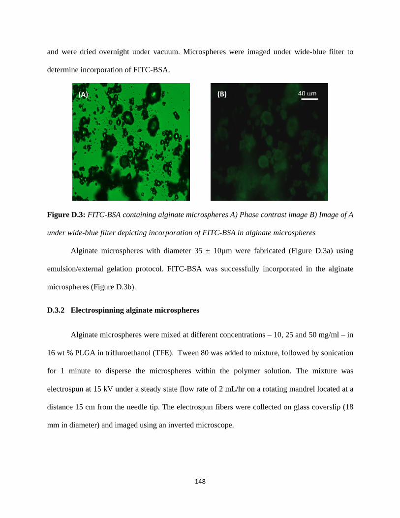
and were dried overnight under vacuum. Microspheres were imaged under wide-blue filter to
determine incorporation of FITC-BSA.
Figure D.3: FITC-BSA containing alginate microspheres A) Phase contrast image B) Image of A
under wide-blue filter depicting incorporation of FITC-BSA in alginate microspheres
Alginate microspheres with diameter 35 ± 10µm were fabricated (Figure D.3a) using
emulsion/external gelation protocol. FITC-BSA was successfully incorporated in the alginate
microspheres (Figure D.3b).
D.3.2 Electrospinning alginate microspheres
Alginate microspheres were mixed at different concentrations – 10, 25 and 50 mg/ml – in
16 wt % PLGA in trifluroethanol (TFE). Tween 80 was added to mixture, followed by sonication
for 1 minute to disperse the microspheres within the polymer solution. The mixture was
electrospun at 15 kV under a steady state flow rate of 2 mL/hr on a rotating mandrel located at a
distance 15 cm from the needle tip. The electrospun fibers were collected on glass coverslip (18
mm in diameter) and imaged using an inverted microscope.
40 µm (A) (B)
148

Figure D.4: Electrospun mesh containing alginate microspheres. Microspheres concentration in
electrospinning solution A) 10 mg/ml B) 25 mg/ml C) 50 mg/ml
The amount of microspheres in the electrospun meshes increased with increasing the
concentration of microspheres in electrospinning solution. At lowest concentration, the
microspheres were embedded within fibers (Figure D.4a). This finding is consistent with study by
Ionescu et al [8], wherein observed that blending of microspheres with electrospinning solution
led to encapsulation of microspheres within the fibers. However, as the concentration of
microspheres increased, a blob of polymer solution containining microspheres was sprayed along
with electrospinning the fibers. This process led to formation of meshes containing two different
areas – one area consisting of few microspheres and other area containing lot of microspheres in
polymer blob. It was hypothesized that the difficulty in electrospinning could have arisen because
of the mirospheres size.
D.3.3 Loading of lysozyme in alginate microsphere
Lysozyme was mixed with alginate solution for 2 hours to achieve a final lysozyme
concentration of 15 µg/ml. This solution was used to synthesize microspheres by using emulsion
protocol as explained above. The microspheres were split in two batches. The first batch of
microspheres were dissolved in 100 mM sodium acetate to determine the amount of lysozyme
40 µm 40 µm 40 µm (A)
(B) (C)
149

loaded in the microsphere. The results indicate that only 20 % of the active lysozyme was
incorporated in the microspheres. The second bathc of microspheres were dispered in PBS to study
the release kinetics of lysozyme from those microspehres. The release kinetics indicated that 99%
of the lysozyme loaded was released in 1 day. This result is consistent with previous studies in
which they observed that alginate gels/microspheres allowed for high diffusion rates of
macromolecules which further led to burst release [9].
The difficulty in electrospinning, poor loading efficiency and burst release of protein made this
microspheres unsuitable for future experimentation. The increase in loading efficiency and
decrease in burst release can be addressed by either incorporating a mineral phase in alginate gel
[10] or coating the alginate gel [9]. It was hypothesized that incorporation of mineral particle
during microsphere synthesis will resolve the issue with size as the process might led to coating
of alginate layer around the mineral particles (and the size of alginate particles will be dictated by
size of mineral) and it will also resolve the issue with release kinetics. Hence alginate microspheres
were modified to incorporate mineral in them.
D.4 Alginate mineral microspheres
β-tri calcium phosphate (TCP) was chosen as the mineral core phase because not only
might it resolve the issues with alginate microspheres it would also help promoting differentiation
of bone marrow stromal cells (BMSCs) towards bone tissue. With this viewpoint, alginate-TCP
microspheres were fabricated to load proteins in them and electrospin them.
D.4.1 Synthesis of TCP based alginate microspheres
TCP was crushed using pestle and mortar and the crushed powder was sieved to collect the
particles with average size of 8µm. Crushed TCP was added to alginate solution and the mixture
150

was sonicated for 20 minutes in bath sonicator to break the chunks of TCP. The mixture was then
stirred overnight to disperse TCP uniformly in alginate solution. The TCP-alginate microspheres
were synthesized using emulsion protocol as explained earlier. The microspheres were washed
with acetone 4 times, followed by washing with DI water and dried under vacuum. Alginate-TCP
microspheres around 13 ± 6 µm were fabricated and FITC-BSA was loaded in them in the particles
(Figure D.5 a and b).
Figure D.5: FITC-BSA loaded alginate-TCP microspheres. A) Phase contrast B) Image under
wide-blue filter demonstrating incorporation of FITC-BSA in alginate-TCP microspheres
D.4.2 Electrospinning alginate-TCP particles:
Alginate-TCP microspheres were added to a solution of 16% (w/w) PLGA in TFE at final
concentration of 25 mg/ml. Tween 80 was added to mixture, followed by sonication for 1 minute
to disperse the microspheres in the polymer solution. The mixture was electrospun at 15 kV under
a steady state flow rate of 2 mL/hr on a rotating mandrel located at a distance 15 cm from needle
tip. The electrospun fibers were collected on glass coverslip (18 mm in diameter) and imaged using
inverted microscope.
20 µm (A) (B)
151

Figure D.6: Electrospun mesh containing alginate-TCP microspheres. A) phase contrast image.
B) Image under wide-blue filter depicting retainment of FITC-BSA within microspheres post
electrospinning.
Electrospinning alginate-TCP microspheres led to formation of meshes containing two
different areas – one area consisting of few microspheres and other area consisting of lot of
microspheres in polymer blob. This observation is consistent with previous observation with
electrospinning alginate microspheres.
D.4.3 Loading and release of lysozyme from alginate TCP microspheres
The solution of 1% (w/v) alginate and lysozyme was mixed to achieve a final concentration
of 25 µg/ml of lysozyme in the feed. TCP was added to the mixture and alginate-TCP microspheres
were synthesized as explained above. The loading efficiency of lysozyme within microspheres was
determined by dissolving some of the microspheres in sodium citrate. The remaining microspheres
were distributed into two batches to study the release kinetics in presence or absence of sodium
citrate in release medium. The release media was replaced with fresh new media at different time
points and frozen in -20 °C till analysis.
40 µm (A) (B)
152

Figure D.7: Release of lysozme from alginate-TCP microspheres. Blue trace indicates release in
presence of PBS and red trace indicates release in presence of PBS and sodium citrate. The purple
line indicates amount of lysozyme that was encapsulated within the microspheres.
The loading efficiency of these microspheres was only was 8%. Furthermore, the release
kinetics indicated a burst release of 70% in first 12 hours. 99% of the protein was released by the
end of 24 hours.
D.5 Conclusions
Although, blend electrospinning, electrospraying, alginate or algiante-mineral
microspheres can be implemented to deliver proteins within electrospun meshes, these approaches
are limited either due to decrease in activity of proteins, or poor loading efficiencies and difficulties
with electrospinning. Hence, there is a need to create a new delivery vehicle which will overcome
all of these issues. Bearing these results in mind, chitiosan-algiante microspheres were fabricated
and tested for loading and release of FITC-BSA (Chapter 3).
153

D.6 References:
[1] Ji W, Sun Y, Yang F, van den Beucken JJ, Fan M, Chen Z, et al. Bioactive electrospun scaffolds delivering growth factors and genes for tissue engineering applications. Pharmaceutical research. 2011;28:1259-72. [2] Madurantakam PA, Rodriguez IA, Beckman MJ, Simpson DG, Bowlin GL. Evaluation of biological activity of bone morphogenetic proteins on exposure to commonly used electrospinning solvents. Journal of Bioactive and Compatible Polymers. 2011;26:578-89. [3] Ji W, Yang F, van den Beucken JJJP, Bian Z, Fan M, Chen Z, et al. Fibrous scaffolds loaded with protein prepared by blend or coaxial electrospinning. Acta Biomaterialia. 2010;6:4199-207. [4] Huang ZM, He CL, Yang A, Zhang Y, Han XJ, Yin J, et al. Encapsulating drugs in biodegradable ultrafine fibers through co-axial electrospinning. Journal of biomedical materials research Part A. 2006;77:169-79. [5] Yang Y, Li X, Qi M, Zhou S, Weng J. Release pattern and structural integrity of lysozyme encapsulated in core–sheath structured poly(dl-lactide) ultrafine fibers prepared by emulsion electrospinning. European Journal of Pharmaceutics and Biopharmaceutics. 2008;69:106-16. [6] Bian L, Zhai DY, Tous E, Rai R, Mauck RL, Burdick JA. Enhanced MSC chondrogenesis following delivery of TGF-beta3 from alginate microspheres within hyaluronic acid hydrogels in vitro and in vivo. Biomaterials. 2011;32:6425-34. [7] Freeman I, Kedem A, Cohen S. The effect of sulfation of alginate hydrogels on the specific binding and controlled release of heparin-binding proteins. Biomaterials. 2008;29:3260-8. [8] Ionescu LC, Lee GC, Sennett BJ, Burdick JA, Mauck RL. An anisotropic nanofiber/microsphere composite with controlled release of biomolecules for fibrous tissue engineering. Biomaterials. 2010;31:4113-20. [9] Strand BL, Gaserod O, Kulseng B, Espevik T, Skjak-Baek G. Alginate-polylysine-alginate microcapsules: effect of size reduction on capsule properties. Journal of microencapsulation. 2002;19:615-30. [10] Perez RA, Kim HW. Core-shell designed scaffolds of alginate/alpha-tricalcium phosphate for the loading and delivery of biological proteins. Journal of biomedical materials research Part A. 2013;101:1103-12.
154

Appendix E
Dynamic Light Scattering Spectrograms
E.1 Effect of varying cation : alginate ratio (CAR) on microsphere size
The microspheres were prepared using 6 mM CaCl2 and high molecular weight alginate.
E.1.1 Microspheres synthesized with CAR – 0.025:
Figure E.1: Representative DLS spectrogram for PLL-AL microspheres at CAR of 0.25
E.1.2 Microspheres synthesized with CAR – 0.05:
Figure E.2: Representative DLS spectrogram for microspheres at CAR – 0.05
-5
0
5
10
15
20
25
0.1 1 10 100 1000 10000
Inte
nsity
(%)
Size d (nm)
0
5
10
15
20
0.1 1 10 100 1000 10000
Inte
nsity
(%)
Size d (nm)
PLL-AL CS-AL
155
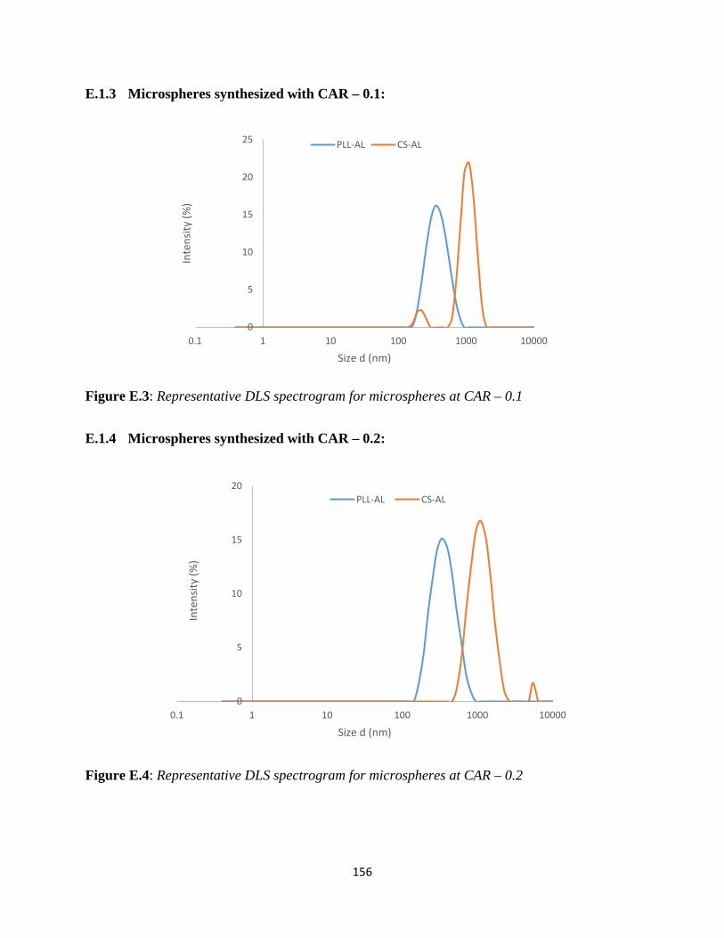
E.1.3 Microspheres synthesized with CAR – 0.1:
Figure E.3: Representative DLS spectrogram for microspheres at CAR – 0.1
E.1.4 Microspheres synthesized with CAR – 0.2:
Figure E.4: Representative DLS spectrogram for microspheres at CAR – 0.2
0
5
10
15
20
25
0.1 1 10 100 1000 10000
Inte
nsity
(%)
Size d (nm)
PLL-AL CS-AL
0
5
10
15
20
0.1 1 10 100 1000 10000
Inte
nsity
(%)
Size d (nm)
PLL-AL CS-AL
156

E.1.5 Microspheres synthesized with CAR – 0.4:
Figure E.5: Representative DLS spectrogram for microspheres at CAR – 0.4
E.1.6 Microspheres synthesized with CAR – 0.8:
Figure E.6: Representative DLS spectrogram for microspheres at CAR – 0.8
0
5
10
15
20
0.1 1 10 100 1000 10000
Inte
nsity
(%)
Size d (nm)
PLL-AL CS-AL
0
5
10
15
20
0.1 1 10 100 1000 10000
Inte
nsity
(%)
Size d (nm)
157

CAR
PLL-AL CS-AL
Peak 1 Peak 1 Peak2
Size % PDI Size % Size % PDI
0.025 466 ± 27 100 0.22±0.03 – – – – –
0.05 410 ± 30 100 0.18±0.02 1242± 30 93 177± 14 7 0.42±0.04
0.1 396 ± 22 100 0.17±0.01 1087± 155 94 205± 21 6 0.44±0.03
0.2 378 ± 20 100 0.22±0.01 1083± 118 98 5560± 438 2 0.26±0.08
0.4 472 ± 42 100 0.3±0.05 853± 83 87 220± 40 13 0.49±0.09
0.8 – – – 1040± 113 99 4890± 348 1 0.53±0.09
Table E.1: Table demonstrating effect of varying CAR on size and poly dispersity index (PDI) of
microspheres
E.2 Effect of varying alginate viscosity on microsphere size
Microspheres were prepared with 6 mM CaCl2 and CAR of 0.1.
E.2.1 Microspheres synthesized with L-alginate (30 Cps)
Figure E.7: Representative DLS spectrogram for microspheres with L-alginate.
0
5
10
15
20
25
0.1 1 10 100 1000 10000
Inte
nsity
(%)
Size d (nm)
PLL-AL CS-AL
158

E.2.2 Microspheres synthesized with M-alginate (250 Cps)
Figure E.8: Representative DLS spectrogram for microspheres with M-alginate.
E.2.3 Microspheres synthesized with H-alginate (2000 Cp):
Figure E.9: Representative DLS spectrogram for microspheres with H-alginate
0
5
10
15
20
0.1 1 10 100 1000 10000
Inte
nsity
(%)
Size d (nm)
PLL-AL CS-AL
0
5
10
15
20
25
0.1 1 10 100 1000 10000
Inte
nsity
(%)
Size d (nm)
PLL-AL CS-AL
159

Alginate
Type
PLL-AL CS-AL
Peak 1 Peak1 Peak2
Size % PDI Size % Size % PDI
L type 490 ± 15 100 0.25±0.01 728± 40 100 – – 0.27±0.17
M type 597 ± 29 100 0.25±0.01 980± 86 93 181± 40 7 0.34±0.08
H type 703± 74 100 0.26±0.04 1087± 155 94 205± 21 6 0.44±0.03
Table E.2: Table demonstrating effect of varying alginate type on size and PDI of microspheres
E.3 Effect of varying CaCl2 concentration on microsphere size
The microspheres were synthesized by using H-alginate and CAR of 0.1
E.3.1 Microspheres synthesized with 3 mM CaCl2
Figure E.10: Representative DLS spectrogram for microspheres with 3 mM CaCl2
0
5
10
15
20
0.1 1 10 100 1000 10000
Inte
nsity
(%)
Size d (nm)
PLL-AL CS-AL
160

E.3.2 Microspheres synthesized with 6 mM CaCl2
Figure E.11: Representative DLS spectrogram for microspheres with 6 mM CaCl2
E.3.3 Microspheres synthesized with 12 mM CaCl2
Figure E.12: Representative DLS spectrogram for microspheres with 12 mM CaCl2
0
5
10
15
20
25
0.1 1 10 100 1000 10000
Inte
nsity
(%)
Size d (nm)
PLL-AL CS-AL
0
5
10
15
20
0.1 1 10 100 1000 10000
Inte
nsity
(%)
Size d (nm)
PLL-AL CS-AL
161

E.3.4 Microspheres synthesized with 24 mM CaCl2
Figure E.13: Representative DLS spectrogram for microspheres with 24 mM CaCl2
E.3.5 Microspheres synthesized with 48 mM CaCl2
Figure E.14: Representative DLS spectrogram for microspheres with 48 mM CaCl2
0
5
10
15
20
0.1 1 10 100 1000 10000
Inte
nsity
(%)
Size d (nm)
PLL-AL CS-AL
0
5
10
15
0.1 1 10 100 1000 10000
Inte
nsity
(%)
Size d (nm)
PLL-AL CS-AL
162

CaCl2
Concen-
tration
PLL-AL CS-AL
Peak1 Peak1 Peak2
Size % PDI Size % Size % PDI
3 527 ± 30 100 0.25±0.03 535 ± 25 98 5105± 328 2 0.23±0.02
6 703± 74 100 0.26±0.04 1087± 155 94 205± 21 6 0.44±0.03
12 797± 20 100 0.15±0.02 932 ± 76 96 152 ± 62 4 0.26±0.02
24 862± 134 100 0.25±0.03 885 ± 6 100 – – 0.21±0.02
48 1334± 151 100 0.26±0.03 967 ± 59 100 – – 0.25±0.01
Table E.3: Table demonstrating effect of varying CaCl2 concentration on size and PDI of
microspheres
163


