
Folie 1
Analog Filtering
Reinhard Keller
This is a little overview of what is done and what is planned against RFI with analogfilters at the Effelsberg Telescope.
Folie 2
Bonn, 30. March 2001RFI Mitigation Workshop2
Analog Filters are everywhere
In the frontends:– at RF stages
– at IF stages
– at DC
In the backends– at IF level
– at DC
Besides many classical filters a lot of shielding is used to avoid RFI. That is whatindustry calls EMC, electro-magnetic compatibility. Filters are also incorporated in theDC connectors.

Folie 3
Bonn, 30. March 2001RFI Mitigation Workshop3
RFI at 21cm in Effelsberg:
The need of RFI mitigation is obvious! Small bands are reserved for astronomy butwideband observation are wanted. Only a few interferers are known. Most of themare changing with time and also in frequency. This delimits hardware filtering
Folie 4
Bonn, 30. March 2001RFI Mitigation Workshop4
Fixed Filters:
Frequency domain: – Bandpassfilter
– Bandstopfilter (Notch)
(Time domain)

Folie 5
Bonn, 30. March 2001RFI Mitigation Workshop5
Fixed Frequency Filters
Before LNA:1. Avoid saturation
(„robust receiver“)
2. Select desired frequencies
→ low loss → high gain stability
After LNA:1. Select desired
frequencies
2. Avoid saturation(„robust receiver“)
→ high selectivity → high gain stability
Folie 6
Bonn, 30. March 2001RFI Mitigation Workshop6
Fixed Frequency Filters
are
simple
Need no info about RFI
but
Seperation of RFI ⇔ signal in frequency domain

Folie 7
Bonn, 30. March 2001RFI Mitigation Workshop7
Example 1: 1.9cm Receiver
Realized at the Effelsberg telscope
Folie 8
Bonn, 30. March 2001RFI Mitigation Workshop8
13 GHz High Pass Filter
-80
-60
-40
-20
0
10 12 14 16 18 20
f/GHz
S/d
B

Folie 9
Bonn, 30. March 2001RFI Mitigation Workshop9
13 GHz High Pass Filter
Insertion loss S21-Betrag
-0.5
-0.4
-0.3
-0.2
-0.1
0
10 12 14 16 18 20
f/GHz
S/d
B
Folie 10
Bonn, 30. March 2001RFI Mitigation Workshop10
13 GHz High Pass Filter
waveguide realization:
Folie 11
Bonn, 30. March 2001RFI Mitigation Workshop11
„Adaptive“ analog filters
Switched filters:– Realized in Effelsberg
Prooved, but after LNA!
Tunable filters: – Waveguide filters;
Mecanicaly tuned in dewar
– HTSC-filters (Uni Wuppertal);Electr. Tuned by ferro elektric – magnetic material
Piezo electric tuning

Folie 12
Bonn, 30. March 2001RFI Mitigation Workshop12
Example 2: 21cm Receiver
Realized filter bank after the LNAFolie 13
Bonn, 30. March 2001RFI Mitigation Workshop13
Example 2: 21cm Receiver
Planned implementation of High Temperature Superconducting Filters. The filtersare realized.Folie 14
Bonn, 30. March 2001RFI Mitigation Workshop14
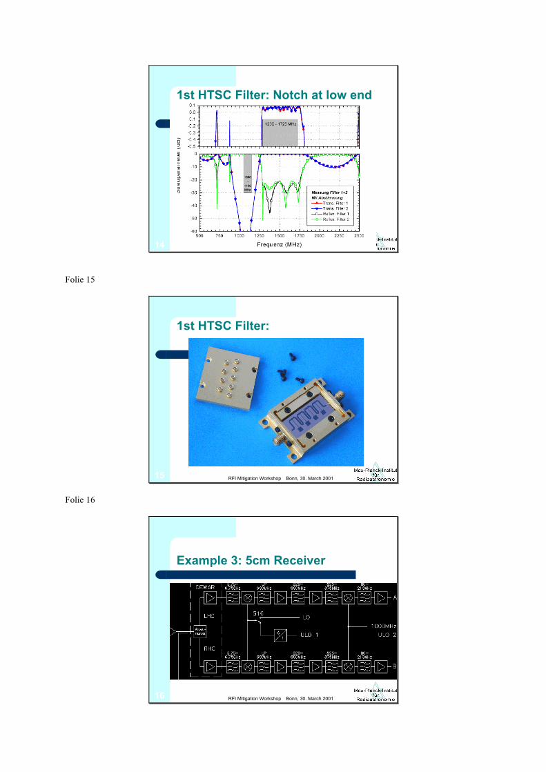
1st HTSC Filter: Notch at low end
Folie 15
Bonn, 30. March 2001RFI Mitigation Workshop15
1st HTSC Filter:
Folie 16
Bonn, 30. March 2001RFI Mitigation Workshop16
Example 3: 5cm Receiver

Folie 17
Bonn, 30. March 2001RFI Mitigation Workshop17
Corrugated bandpass filter
Folie 18
Bonn, 30. March 2001RFI Mitigation Workshop18
Corrugated bandpass filter
Fcenter=6.2GHz, RBW=21%; simulation results:
Folie 19
Bonn, 30. March 2001RFI Mitigation Workshop19
CMT + Bandpass integrated
Currently under developmentFolie 20

Bonn, 30. March 2001RFI Mitigation Workshop20
What will be realistic?
In the dewar:– low frequencies > 3 GHz:
1. (tuneable) HTSC filters
– medium frequencies :1. (tunable) waveguide filters
– high frequencies > 30 GHz: fixed waveguide filters
At room temperature:– filters of any kind


