
Analogue Instrumentation for Engineering Testing
• This week in lab – Your first instrumentation lab period– Meet your instructor (Dustin Grissom, Steve Edwards)– Learn about analogue instrumentation– Prepare by reading “Instrumentation Lab Overview”
and “Analogue Instrumentation (+Review?)” sections of manual, and by doing homework.
– Homework problem set due at start of lab period• Each team should bring to lab:
– A laptop– A printout of the Analogue Instrumentation chapter
from the course manual– A printout of the slides to be used in lab (in manual).
Print 6 per page

Instrumentation Lab
• Learn about basic instrumentation used in modern test and measurement systems for aerospace and ocean engineering applications. Such systems comprise a mixture of analogue electronic devices, like sensors and actuators, with digital data acquisition and control.
• Five Periods– Analogue instrumentation– Application (Dynamic Beam Response Experiment)– Measuring with Computers– Spectral Analysis with Computers– Application (Re-run of Beam Response)
LabView
Today• Analogue Instrumentation
– Power supply– Multimeter– Function generator– Counter– Oscilloscope– Amplifier
• Background needed to use it– Current and Voltage– Properties affecting current and voltage– Connecting Equipment
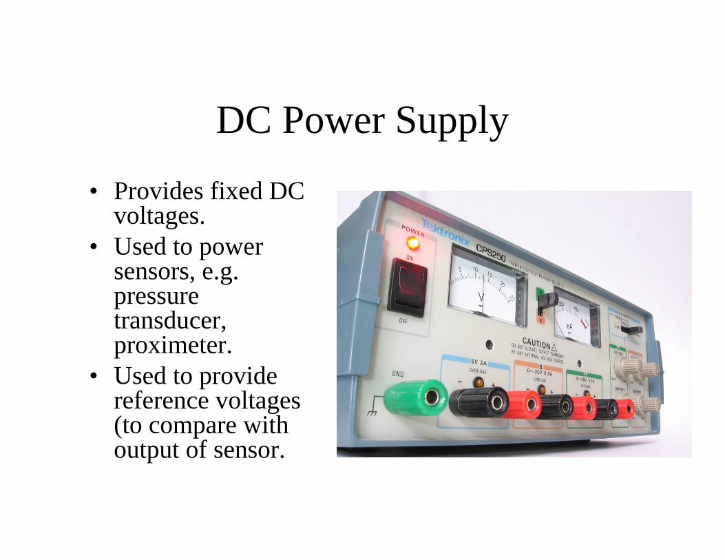
DC Power Supply
• Provides fixed DC voltages.
• Used to power sensors, e.g. pressure transducer, proximeter.
• Used to provide reference voltages (to compare with output of sensor.

Multimeter
• Measures resistance, voltages and currents (DC and RMS)
• Used to measure/check transducer properties (e.g. resistance of strain gage)
• Used to check connections
• Used to check measurement system outputs (voltage from pressure transducer output, r.m.s. voltage from turbulent velocity signal)
• …and inputs (say to computer measurement system)

Function generator and counter
• Generates simple periodic voltage signals (sine, square, triangular) with controlled amplitude and frequency.
• Used to provide fluctuating inputs for experiments or for checking hardware (esp. when measuring dynamic response)
• Used to trigger events (like camera timing, taking a computerized measurement)
• Measures the frequency of simple periodic voltage signals
• Used with function generator testing dynamic response of experimental set-ups or measurement hardware.
• Used to measure frequency of physical phenomena (rarely though– they are not usually simple and periodic enough)

Oscilloscope• Used to visualize
your measured signal to make sure its right (e.g. LDA bursts)
• Used to measure amplitude and phase of fluctuating signals

Amplifiers
• Often unassuming. Huge variety
• Will see around lab.• Changes the amplitude
of a fluctuating signal (e.g. amplify weak signal)
• Transforms output impedance (more later)

Background needed to use this equipment
1. Current and Voltage2. Properties affecting current and voltage3. Connecting Equipment
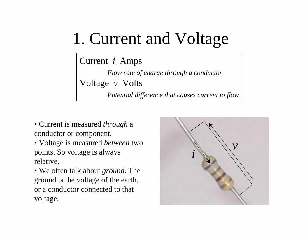
1. Current and VoltageCurrent i Amps
Flow rate of charge through a conductorVoltage v Volts
Potential difference that causes current to flow
iv
• Current is measured through a conductor or component. • Voltage is measured between two points. So voltage is always relative.• We often talk about ground. The ground is the voltage of the earth, or a conductor connected to that voltage.
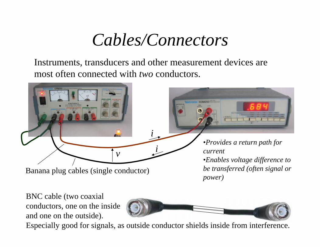
Instruments, transducers and other measurement devices are most often connected with two conductors.
Cables/Connectors
i•Provides a return path for current•Enables voltage difference to be transferred (often signal or power)
v
i
Banana plug cables (single conductor)
BNC cable (two coaxial conductors, one on the inside and one on the outside). Especially good for signals, as outside conductor shields inside from interference.
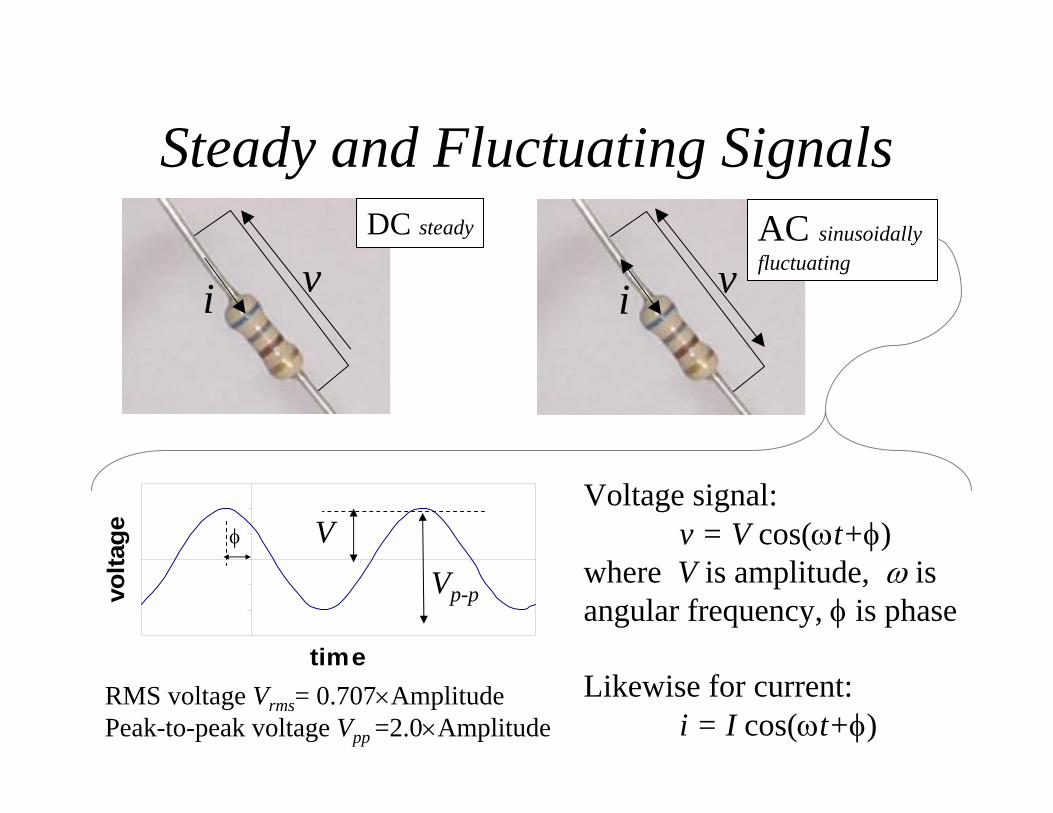
Steady and Fluctuating Signals
i vi vDC steady
Voltage signal:v = V cos(ωt+φ)
where V is amplitude, ω isangular frequency, φ is phase
Likewise for current: i = I cos(ωt+φ)
time
volta
ge Vφ
AC sinusoidallyfluctuating
Vp-p
RMS voltage Vrms= 0.707×AmplitudePeak-to-peak voltage Vpp =2.0×Amplitude
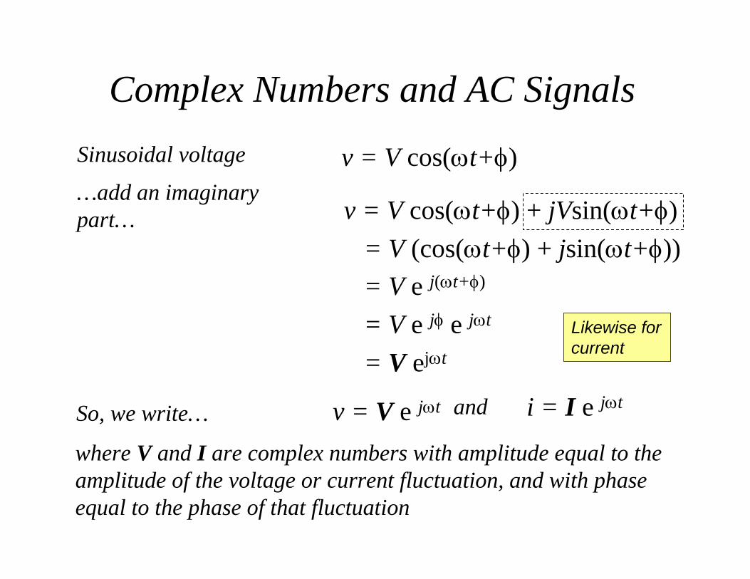
Complex Numbers and AC Signals
where V and I are complex numbers with amplitude equal to the amplitude of the voltage or current fluctuation, and with phase equal to the phase of that fluctuation
v = V e jωt i = I e jωtSo, we write…
…add an imaginary part… v = V cos(ωt+φ) + jVsin(ωt+φ)
= V (cos(ωt+φ) + jsin(ωt+φ))= V e j(ωt+φ)
= V e jφ e jωt
= V ejωt
Likewise for current
Sinusoidal voltage v = V cos(ωt+φ)
and

Application
F-22 model with instrumented vertical tails undergoes buffet tests in the 16-Foot Transonic Dynamics Tunnel at NASA Langley.
iv
Kulite IS Pressure Transducer.
• Transducers• Cables• Instrumentation
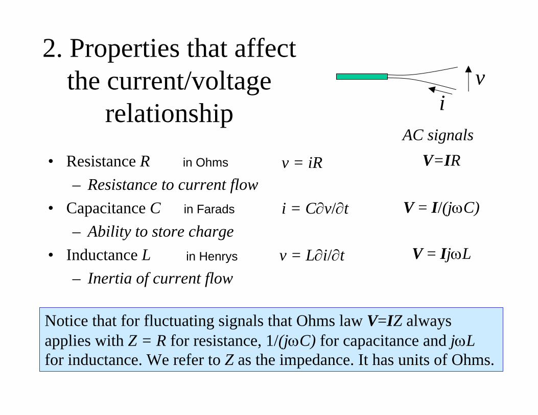
2. Properties that affect the current/voltage
relationship• Resistance R
– Resistance to current flow• Capacitance C
– Ability to store charge• Inductance L
– Inertia of current flow
iv
v = iR
i = C∂v/∂t
v = L∂i/∂t
AC signalsV=IR
V = I/(jωC)
V = IjωL
Notice that for fluctuating signals that Ohms law V=IZ always applies with Z = R for resistance, 1/(jωC) for capacitance and jωLfor inductance. We refer to Z as the impedance. It has units of Ohms.
in Ohms
in Farads
in Henrys
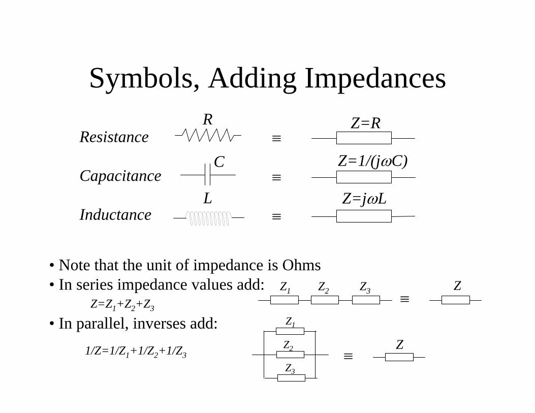
Symbols, Adding Impedances
Resistance
Capacitance
Inductance
R
C
L
≡
≡
≡
Z=R
Z=1/(jωC)
Z=jωL
• Note that the unit of impedance is Ohms• In series impedance values add:
• In parallel, inverses add:≡
Z1 Z2 Z3
Z=Z1+Z2+Z3
≡
Z1
Z2
Z3
1/Z=1/Z1+1/Z2+1/Z3
Z
Z

Example - Adding ImpedancesExample: What is the relationship between the voltage amplitude V across the components shown below, and the current amplitude I through them?
L
C
RI
V
Z1=jωL
Z2=1/(jωC)
Z3=R
Circuit can be redrawn as:
Using rules on previous slide we have that the total impedance
or, substituting,
or,
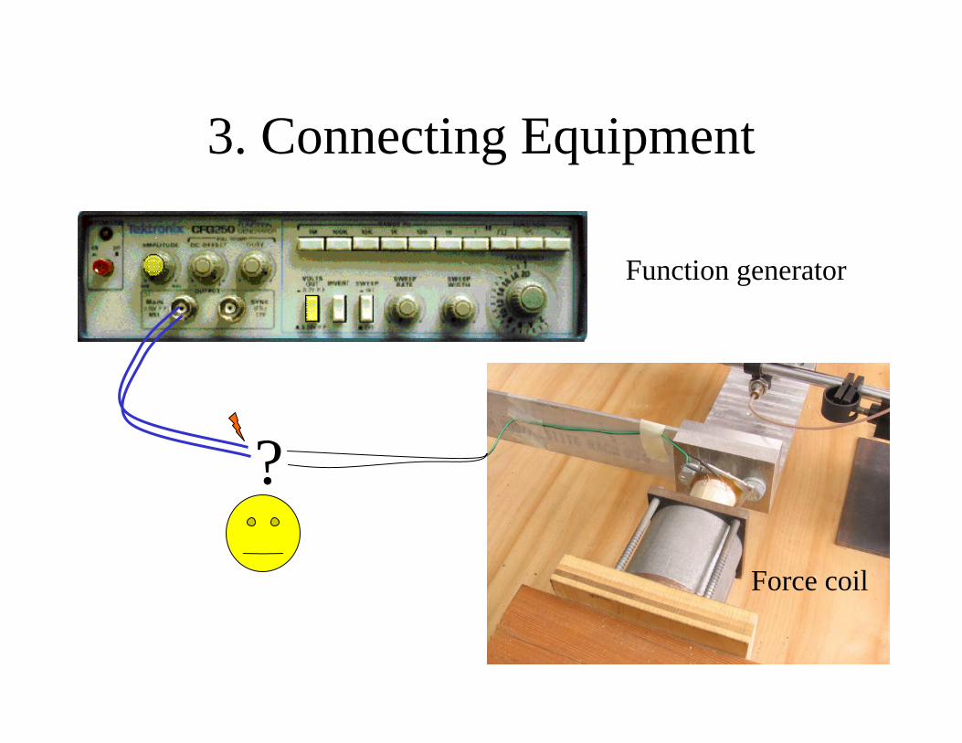
3. Connecting Equipment
Function generator
Force coil
?
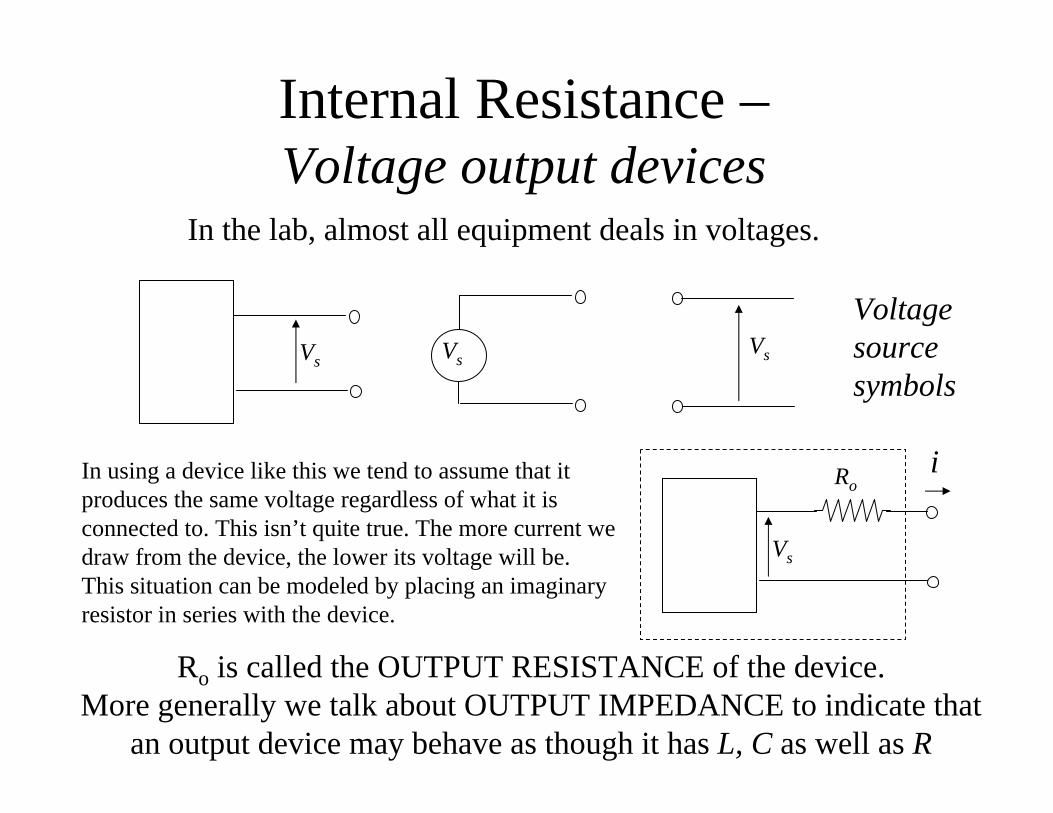
Internal Resistance –Voltage output devices
In the lab, almost all equipment deals in voltages.
In using a device like this we tend to assume that it produces the same voltage regardless of what it is connected to. This isn’t quite true. The more current we draw from the device, the lower its voltage will be. This situation can be modeled by placing an imaginary resistor in series with the device.
Vs
Roi
Ro is called the OUTPUT RESISTANCE of the device.More generally we talk about OUTPUT IMPEDANCE to indicate that
an output device may behave as though it has L, C as well as R
Vs VsVs
Voltage source symbols

Internal Resistance -Voltage input devices
In using a device like this we tend to assume that the device does not alter the voltage fed to it. This isn’t quite true. This is only possible if the device draws no current. In reality some current is always drawn. This situation can be modeled by placing an imaginary resistor in parallel with the device
V GV V
Ri
i
V
Ri is called the INPUT RESISTANCE of the deviceMore generally we talk about INPUT IMPEDANCE to indicate that
an input device may behave as though it has L, C as well as R
Circuit symbols

Example - Connecting equipment
RiV1
Ro
V2
Temperature sensor Voltmeter
What is the relationship between the voltage we want to sense V1 and the voltage we actually sense V2?
Using Ohm’s Law:
A good lab instrument is thus one with high input impedance (106Ω)and low output impedance (1Ω)
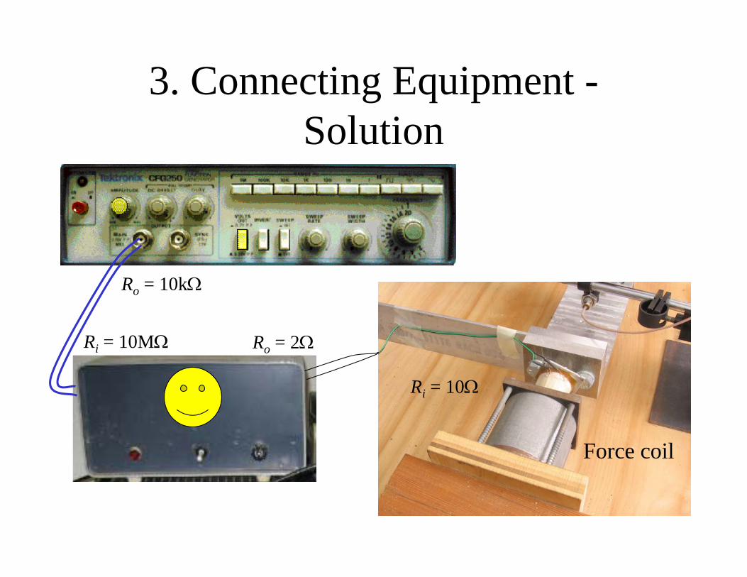
3. Connecting Equipment -Solution
Force coil
Ro = 10kΩ
Ri = 10Ω
Ri = 10MΩ Ro = 2Ω

( ) ( )RV t RI t=
( ) ( )RV s RI s=
( )( )
RR
V jR Z
I jωω
= =
( ) 1cV t idt
C= ∫
( ) ( )1 1cV s I s
s C=
( )( )
1 1cC
V jZ
I j j Cωω ω
= =
Resistance Capacitance
Impedance Impedance
Impedance using Laplace Transforms
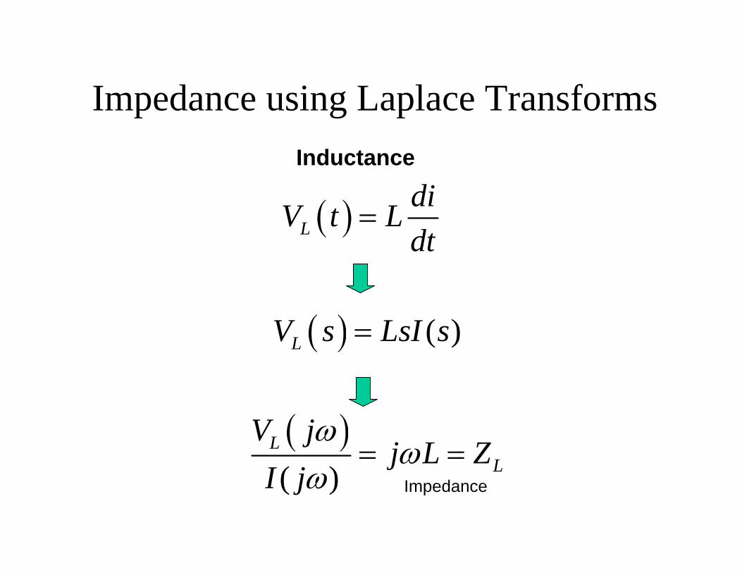
Inductance
Impedance
Impedance using Laplace Transforms
( )LdiV t Ldt
=
( ) ( )LV s LsI s=
( )( )
LL
V jj L Z
I jω
ωω
= =


